EP2505897B1 - Pressverbindung für Kunststoffrohre - Google Patents
Pressverbindung für Kunststoffrohre Download PDFInfo
- Publication number
- EP2505897B1 EP2505897B1 EP12151388.1A EP12151388A EP2505897B1 EP 2505897 B1 EP2505897 B1 EP 2505897B1 EP 12151388 A EP12151388 A EP 12151388A EP 2505897 B1 EP2505897 B1 EP 2505897B1
- Authority
- EP
- European Patent Office
- Prior art keywords
- tube
- ring groove
- annular ring
- compression
- sleeve
- Prior art date
- Legal status (The legal status is an assumption and is not a legal conclusion. Google has not performed a legal analysis and makes no representation as to the accuracy of the status listed.)
- Revoked
Links
Images

Classifications
-
- F—MECHANICAL ENGINEERING; LIGHTING; HEATING; WEAPONS; BLASTING
- F16—ENGINEERING ELEMENTS AND UNITS; GENERAL MEASURES FOR PRODUCING AND MAINTAINING EFFECTIVE FUNCTIONING OF MACHINES OR INSTALLATIONS; THERMAL INSULATION IN GENERAL
- F16L—PIPES; JOINTS OR FITTINGS FOR PIPES; SUPPORTS FOR PIPES, CABLES OR PROTECTIVE TUBING; MEANS FOR THERMAL INSULATION IN GENERAL
- F16L33/00—Arrangements for connecting hoses to rigid members; Rigid hose connectors, i.e. single members engaging both hoses
- F16L33/20—Undivided rings, sleeves or like members contracted on the hose or expanded in the hose by means of tools; Arrangements using such members
- F16L33/207—Undivided rings, sleeves or like members contracted on the hose or expanded in the hose by means of tools; Arrangements using such members only a sleeve being contracted on the hose
-
- F—MECHANICAL ENGINEERING; LIGHTING; HEATING; WEAPONS; BLASTING
- F16—ENGINEERING ELEMENTS AND UNITS; GENERAL MEASURES FOR PRODUCING AND MAINTAINING EFFECTIVE FUNCTIONING OF MACHINES OR INSTALLATIONS; THERMAL INSULATION IN GENERAL
- F16L—PIPES; JOINTS OR FITTINGS FOR PIPES; SUPPORTS FOR PIPES, CABLES OR PROTECTIVE TUBING; MEANS FOR THERMAL INSULATION IN GENERAL
- F16L13/00—Non-disconnectible pipe-joints, e.g. soldered, adhesive or caulked joints
- F16L13/14—Non-disconnectible pipe-joints, e.g. soldered, adhesive or caulked joints made by plastically deforming the material of the pipe, e.g. by flanging, rolling
- F16L13/141—Non-disconnectible pipe-joints, e.g. soldered, adhesive or caulked joints made by plastically deforming the material of the pipe, e.g. by flanging, rolling by crimping or rolling from the outside
- F16L13/143—Non-disconnectible pipe-joints, e.g. soldered, adhesive or caulked joints made by plastically deforming the material of the pipe, e.g. by flanging, rolling by crimping or rolling from the outside with a sealing element placed around the male part before crimping or rolling
-
- F—MECHANICAL ENGINEERING; LIGHTING; HEATING; WEAPONS; BLASTING
- F16—ENGINEERING ELEMENTS AND UNITS; GENERAL MEASURES FOR PRODUCING AND MAINTAINING EFFECTIVE FUNCTIONING OF MACHINES OR INSTALLATIONS; THERMAL INSULATION IN GENERAL
- F16L—PIPES; JOINTS OR FITTINGS FOR PIPES; SUPPORTS FOR PIPES, CABLES OR PROTECTIVE TUBING; MEANS FOR THERMAL INSULATION IN GENERAL
- F16L33/00—Arrangements for connecting hoses to rigid members; Rigid hose connectors, i.e. single members engaging both hoses
- F16L33/20—Undivided rings, sleeves or like members contracted on the hose or expanded in the hose by means of tools; Arrangements using such members
- F16L33/207—Undivided rings, sleeves or like members contracted on the hose or expanded in the hose by means of tools; Arrangements using such members only a sleeve being contracted on the hose
- F16L33/2071—Undivided rings, sleeves or like members contracted on the hose or expanded in the hose by means of tools; Arrangements using such members only a sleeve being contracted on the hose the sleeve being a separate connecting member
- F16L33/2078—Undivided rings, sleeves or like members contracted on the hose or expanded in the hose by means of tools; Arrangements using such members only a sleeve being contracted on the hose the sleeve being a separate connecting member connected to the rigid member via an intermediate element
Definitions
- the invention relates to a press connection for plastic pipes and in particular for metal composite pipes with a support sleeve for pushing a pipe and with a compression sleeve for Pressfix réelle the tube on the support sleeve, wherein the support sleeve is provided with an O-ring groove and at least one sawtooth, wherein Both the groove and the saw tooth profile extend circumferentially, while the profiling is formed in the radial direction, according to claim 1.
- the single O-ring S has one Height on, such that the gap C can be closed by expansion of the O-ring even after the Materiälschwund the material of the hose.
- the support sleeve In press connections, in particular for metal composite pipes, it is customary to provide two O-rings on a support sleeve of a press connection and above each of these O-rings, which are usually rubber rings, an overlying compression sleeve full or teilumfnaturelich to press, so as to spend the inner plastic skin of a metal composite pipe in a permanently sealing contact with the O-rings.
- the support sleeve is usually formed with a plurality of sawtooth profiles. The pair of crimping in conjunction with the sawtooth profiles then allows a tight and mechanically stable connection.
- the advantages to be achieved according to the present invention are based on the fact that the support sleeve is provided with only a single O-ring groove, wherein one of its radial edges merges directly into the radially rising profile of the at least one sawtooth profile.
- the transition occurs at a preferably more than half the depth of the sawtooth profile, preferably at full depth of the sawtooth profile, for example compared to other, further sawtooth profiles, on the support sleeve or a conventional sawtooth structure.
- the feltretepröfil adjacent to the opposite edge of the O-ring groove directly from the edge of the O-ring groove protrudes.
- the steep flank of the adjacent sawtooth profile coincides with the flank of the O-ring groove.
- this edge is preferably arranged in the direction of the push-on direction of the tube in front of the O-ring within the O-ring groove.
- the O-ring groove can be dimensioned so that the O-ring also protrudes in the radial direction, but then a calibration of the end of the Anlagenschiebenden pipe must be done, which requires an additional complicated operation and a matching tool with a Kalibrierdorn.
- the press connection is formed with features according to the invention with a support sleeve which tapers conically at the pipe connection side.
- a deformed even at the end metal composite layer tube can be slid onto the support sleeve and under the overlying compression sleeve without difficulty.
- the sawtooth profile which rises obliquely directly from an edge of the O-ring groove, has a steeper and a less steep flank. The less steep flank rises out of the O-ring groove.
- the steep flank e.g. is inclined between 90 ° and 85 ° to the axial direction of the support sleeve, coincide with an edge of the O-ring groove.
- the edge of the O-ring groove opposite the less steep flank of the subsequent sawtooth profile coincides with the steep flank of a sawtooth profile disposed in front of the O-ring groove.
- further sawtooth profiles can be provided in front of and / or behind the O-ring groove in which the O-ring can be located.
- a number of 1 to 3 sawtooth profiles in front of and a number of 2 to 4 sawtooth profiles behind the O-ring groove in the push-on direction has proved to be particularly advantageous.
- a mechanically stable fixation of the metal composite tube which can be made up of at least one inner plastic layer, a surrounding metal layer, usually an aluminum foil, and an outer plastic layer can be realized particularly well with the compressed press connection while saving material.
- the compression sleeve of the press connection according to the invention in the axial direction of the press connection at its pipe connection side opposite end is formed with a plastic ring which surrounds the outer circumference of the compression sleeve and which is provided over the associated end side radially inwardly with an engagement lip which is provided with a locking groove in the support sleeve can be brought into engagement.
- the engagement lip can also provide a galvanic separation, so that the metal layer of the metal composite pipe can not come into electrical contact with the metal portion of the press connection according to the invention.
- the support sleeve is formed at its pipe connection side opposite the end with a shoulder against which an inner plastic layer of the Metal composite pipe can start when pushed, wherein the shoulder or stop in the radial direction is extended so that the shoulder or stop of the metal layer of a deferred metal composite pipe is particularly radially spaced. In this way, a galvanic isolation can be provided in an advantageous manner.
- the outer diameter of the support sleeve is smaller than the inner diameter of the tube, so that when the press connection with the inserted tube is not yet compressed, a leak occurs. In this way, it is possible to determine, for example, when installing a piping system within a building, when a press connection has not been crimped. Due to the leak water will leak and already in the shell construction phase, the compression can catch up, which helps avoid later damage.
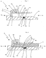
- Fig. 1 is a press connection with the reference numeral 10 has been named.
- the press connection 10 has an extension-side end 10b and an extension-side end 10a opposite the extension-side end, wherein the axial direction of the compression connection is substantially runs parallel to a generally cylindrical support sleeve 12 and a likewise generally cylindrical compression sleeve 14.
- the support sleeve 12 is on the extension side, ie, formed from the side 10b of the press connection ago, with a longer chamfer 20 or slip-20, which allows both deformed pipe ends, as well as pipe ends, which are not only deformed, but also not calibrated , postpone on the support sleeve 12.
- the support sleeve 12 is formed with a plurality of sawtooth structures 22a, which extend radially and are provided in the circumferential direction of the support sleeve fully.
- a first saw tooth 22a is provided which immediately merges into an ⁇ -ring groove 24 in which an O-ring is provided, which is sunk in both the O-ring groove 24.
- the O-ring for example made of rubber or plastic material, has the same outer diameter as corresponds to the depth of the O-ring groove 24.
- the O-ring groove can be at a diameter of the O-ring of about 1.5 mm
- a width of the O-ring groove of 1.8 mm for a nominal diameter of the connection for example, 15 mm
- the depth of the O-ring groove can also be about 1.5 mm for an O-ring with a diameter of about 1.5 mm.
- the O-ring groove can also be formed flatter, that is, for example, 1.2 to 1.4 mm or lower, for example, 1.6 to 1.8 mm.
- leading edge 24b of the O-ring groove 24 coincides with the steep flank of a sawtooth structure 22c leading the O-ring groove.
- This sawtooth structure 22c enables a particularly resistant mechanical fixing of the pressed metal composite pipe.
- a shoulder 13 is formed, against which the inner plastic layer of a metal composite pipe can start, in order to enable a galvanic separation of the metal layer of the metal composite pipe and of the press connection.
- a latching groove 12a may be provided into which a plastic ring 16 can engage with an engagement lip 16b in order to fix a compression sleeve 14 of the press connection 10 to the support sleeve 12.
- the compression sleeve 14 may be formed with a circumferential groove 14a into which a ridge 16a of the curette ring 16, which is also at least partially provided, is able to engage in order to be able to hold the compression sleeve 14 at the press connection, without risking losing the compression sleeve or that a displacement of the compression sleeve during compression can occur.
- the plastic ring can also be molded on.
- Fig. 2 is the press connection, which has proved to be particularly advantageous in particular with respect to the pipe joints for pipes with nominal widths of 16 mm and 20 mm, with a compressed tube 8 therein. It can be clearly seen that the plastic material of the tube is particularly intimately displaced into the overall structure from the O-ring groove 24 and the sawtooth 22b with its smaller slope 24b '. This leads to a mechanically and hydraulically particularly advantageous press connection.
- the pressure in the axial direction has a width of at least 2 mm or more and may extend fully or partially.
- FIG. 3 shows in its sections a and b two support sleeves 12 'and 12 "with modified, structures.
- the support sleeve 12 "differs therefrom in that the flank 22b" b is designed to be longer and, for example, longer than the flanks of the other sawtooth structures 22d, 22a, 22c.
- the flank 24a "can therefore be made particularly low.
- the O-ring groove may also be preceded by a circumferentially and radially unstructured "toothless" area (not shown).
- One or more sawtooth structures 22 c can also be connected to them, counter to the pipe feed direction.
- the edge slopes of the sawtooth structures can be the same or different and move in the known angular ranges.
Description
- Die Erfindung betrifft eine Pressverbindung für Kunststoffrohre und insbesondere für Metall-Verbundrohre mit einer Stützhülse zum Aufschieben eines Rohres und mit einer Presshülse zur Pressfixierung des Rohres auf der Stützhülse, wobei die Stützhülse mit einer O-Ringnut und mit mindestens einem Sägezahnprofil versehen ist, wobei sich sowohl die Nut als auch das Sägezahnprofil umfänglich erstrecken, während die Profilierung in Radialrichtung ausgebildet ist, nach dem Anspruch 1.
- Aus der
JP 2003 028 367 A - Bei Pressverbindungen insbesondere für Metall-Verbundrohre ist es üblich, zwei O-Ringe auf einer Stützhülse einer Pressverbindung vorzusehen und oberhalb jedes dieser O-Ringe, die in der Regel Gummiringe sind, eine darüber befindliche Presshülse vollumfänglich oder teilumfänglich zu verpressen, um somit die innere Kunststoffhaut eines Metall-Verbundrohres in eine dauerhaft dichtende Anlage an die O-Ringe zu verbringen. Um eine mechanische Fixierung des Rohres in der Pressverbindung zu schaffen, ist die Stützhülse in der Regel mit mehreren Sägezahnprofilen ausgebildet. Das Paar von Verpressungen in Verbindung mit den Sägezahnprofilen ermöglicht dann eine dichte und mechanisch stabile Verbindung.
- Die Grundmaterialien für derlei Pressverbindungen werden nachhaltig teurer, so dass die Kosten für diese Pressverbindungen analog dazu steigen. Das zeigt, dass es prinzipiell wünschenswert wäre, bei gleichbleibender Qualität der Pressverbindung einen geringeren Materialaufwand investieren zu müssen, um eine zuverlässige Pressverbindung bereitstellen zu können.
- Gemäß der vorliegenden Erfindung wird dies durch eine Pressverbindung mit dem im Anspruch 1 aufgeführten Merkmalen erreicht.
- Die Vorteile, die gemäß der vorliegenden Erfindung zu erzielen sind, beruhen darauf, dass die Stützhülse lediglich mit einer einzigen O-Ringnut versehen wird, wobei eine ihrer radialen Flanken direkt in das radial ansteigende Profil des wenigstens einen Sägezahnprofils übergeht. Der Übergang erfolgt bei einer bevorzugt mehr als halben Tiefe des Sägezahnprofils, vorzugsweise bei voller Tiefe des Sägezahnprofils, beispielsweise verglichen mit anderen, weiteren Sägezahnprofilen, an der Stützhülse oder einer üblichen Sägezahnstruktur.
- Bevorzugt geht das Sägezahnpröfil, das an die gegenüberliegende Flanke der O-Ringnut angrenzt, unmittelbar aus der Flanke der O-Ringnut hervor. Das heißt, die steile Flanke des angrenzenden Sägezahnprofils stimmt mit der Flanke der O-Ringnut überein. Dabei ist diese Flanke bevorzugt in Richtung der Aufschubrichtung des Rohres vor dem O-Ring innerhalb der O-Ringnut angeordnet.
- Damit ergeben sich folgende Vorteile: Insbesondere, wenn der O-Ring einen Außendurchmesser hat, der kleiner dem Außendurchmesser der Stützhülse ist, wird ein scharfkantiges Rohr bzw. Metall-Mehrschichtverbundrohr, das auf die erfindungsgemäße Pressverbindung aufgeschoben wird, keinen Kontakt zu der Oberfläche des O-Ringes bekommen, so dass der O-Ring nicht verletzt und damit in seiner Dichtwirkung beeinträchtigt werden kann. Dies hat zur Folge, dass eine Kalibrierung der Stirnseite des aufzuschiebenden Rohres nicht erforderlich ist.
- Ferner ist es möglich, mit nur einer umfänglichen bzw. teilumfänglichen Verpressung oberhalb des einen O-Ringes innerhalb der einen einzigen O-Ringnut zu arbeiten, wofür als Verpresswerkzeug eine Verpresszange mit einer Kontur namens TH-Kompakt besonders geeignet ist. Diese ermöglicht eine Verpressung von etwa 2 mm Breite oder mehr in Axialrichtung der Stützhülse bzw. der Pressverbindung. Durch die unmittelbar angrenzende Flanke eines Sägezahns kann durch die Verpressung Kunststoffmaterial an der Innenwand des Metall-Verbundrohres großflächig in Anlage an den O-Ring gebracht werden, so dass durch eine einzige Verpressung eine hinreichende Dichtigkeit bewerkstelligt werden kann. Zudem ist es möglich, dass die Sägezahnstruktur in Aufschubrichtung des Rohres vor der O-Ringnut besonders tief in die Kunststoffinnenschicht des Metall-Verbundrohres eingreift, um somit einen besonders innigen und mechanisch widerstandsfähigen Kontakt zwischen dem Metall-Verbundrohr und der Stützhülse herzustellen. Natürlich kann die O-Ringnut so bemessen sein, dass der O-Ring in Radialrichtung auch übersteht, wobei dann jedoch eine Kalibrierung des Endes des aufzuschiebenden Rohres erfolgen muss, was einen zusätzlichen komplizierteren Arbeitsschritt sowie ein passendes Werkzeug mit einem Kalibrierdorn erfordert.
- Mit der erfindungsgemäßen Ausbildung ist es möglich, die Abmessungen der Pressverbindung kleiner und damit materialeinsparend auszubilden, so dass erhebliche Kostenersparnisse ermöglicht werden können.
- Bevorzugt ist die Pressverbindung mit Merkmalen gemäß der Erfindung mit einer Stützhülse ausgebildet, die rohranschlussseitig konisch zuläuft. Hierdurch kann ohne Mühe ein auch am Ende deformiertes Metall-Verbundschichtrohr auf die Stützhülse und unter die darüber befindliche Presshülse aufgeschoben werden.
- Wie oben bereits angedeutet, hat das Sägezahnprofil, das unmittelbar aus einer Flanke der O-Ringnut schräg ansteigt, eine steilere und eine weniger steile Flanke. Die weniger steile Flanke steigt dabei aus der O-Ringnut heraus an.
- Bevorzugt kann die steile Flanke, die z.B. zwischen 90° und 85° zur Axialrichtung der Stützhülse geneigt ist, mit einer Flanke der O-Ringnut übereinstimmen. Das heißt, dass beispielsweise die der weniger steilen Flanke des anschließenden Sägezahnprofils gegenüberliegende Flanke der O-Ringnut mit der steilen Flanke eines der O-Ringnut vorgelagerten Sägezahnprofils übereinstimmt. Auf diese Weise kann die innere Kunststoffschicht des Metall-Verbundrohres, die durch die Verpressung der erfindungsgemäßen Pressverbindung in die 0-Ringnut nebst der daraus ansteigenden Sägezahnstruktur hineingedrängt wird, einen gegen ein Ausreißen des verpressten Metall-Verbundrohres gerichteten Widerstand bewerkstelligen.
- Zur weiteren mechanischen Stabilisierung der Pressverbindung können vor und/oder hinter der O-Ringnut, in der sich der O-Ring befinden kann, weitere Sägezahnprofile vorgesehen sein. Eine Anzahl von 1 bis 3 Sägezahnprofilen vor und eine Anzahl von 2 bis 4 Sägezahnprofilen hinter der O-Ringnut in Aufschubrichtung hat sich als besonders vorteilhaft erwiesen. Hier kann eine mechanisch stabile Fixierung des Metall-Verbundrohres, das aus mindestens einer inneren Kunststoffschicht, einer diese umgebenden Metallschicht, in der Regel einer Alufolie, und einer äußeren Kunststoffschicht aufgebaut sein kann, mit der verpressten Pressverbindung bei gleichzeitiger Materialeinsparung besonders gut realisiert werden.
- Vorteilhafterweise ist die Presshülse der erfindungsgemäßen Pressverbindung in Axialrichtung der Pressverbindung an ihrem der Rohranschlussseite gegenüberliegenden Ende mit einem Kunststoffring ausgebildet, der die Presshülse außenumfänglich umschließt und der über die zugeordnete Stirnseite hinweg radial nach innen mit einer Eingriffslippe versehen ist, die mit einer Rastrille in der Stützhülse in Eingriff bringbar ist. Auf diese Weise kann die Presshülse dauerhaft und auch für die Montage sicher an ihrem Bestimmungsort gehalten werden. Ferner kann die Eingriffslippe auch eine galvanische Trennung zur Verfügung stellen, so dass die Metallschicht des Metall-Verbundrohres nicht in einem elektrischen Kontakt zu dem Metallabschnitt der erfindungsgemäßen Pressverbindung gelangen kann.
- Ferner ist es vorteilhaft, wenn die Stützhülse an ihrem der Rohranschlussseite gegenüberliegenden Ende mit einem Absatz ausgebildet ist, gegen den eine innere Kunststoffschicht des Metall-Verbundrohres beim Aufschieben anlaufen kann, wobei der Absatz oder Anschlag in Radialrichtung so erstreckt ist, dass der Absatz oder Anschlag von der Metallschicht eines aufgeschobenen Metall-Verbundrohres insbesondere radial beabstandet ist. Auch auf diese Weise lässt sich eine galvanische Trennung in vorteilhafter Weise zur Verfügung stellen.
- Weitere Vorteile lassen sich erschließen, wenn der Außendurchmesser der Stützhülse kleiner ausgebildet ist, als der Innendurchmesser des Rohres, so dass, wenn die Pressverbindung mit dem eingeführten Rohr noch nicht verpresst ist, eine Undichtigkeit auftritt. Auf diese Weise ist es möglich, beispielsweise bei der Installation eines Rohrleitungssystems innerhalb eines Gebäudes festzustellen, wenn eine Pressverbindung nicht verpresst worden ist. Durch die Undichtigkeit wird Wasser austreten und bereits in der Rohbauphase lässt sich die Verpressung nachholen, was spätere Schäden vermeiden hilft.
- Nachfolgend wird die vorliegende Erfindung näher erläutert, wobei weitere erfinderische Merkmalen sowie Vorteile der Erfindung offenbart werden. Es wird keine Ausführungsform der Erfindung gezeigt. In den Figuren zeigen:
-
Fig. 1 einen axialen Längsschnitt durch ein Ende einer Pressverbindung, die zum Stand der Technik gehört; -
Fig. 2 eine Schnittansicht gemäßFig. 1 mit einem darin befindlichen und verpressten Rohr; und -
Fig. 3 weitere Beispiele für Oberflächenstrukturen einer Stützhülse. - Bezüglich der
Fig. 1 benannte und beschriebene Bestandteile sind mit übereinstimmenden Bezugszeichen in den nachfolgenden Figuren bezeichnet, so dass eine mehrfache Beschreibung gleicher Elemente nicht erforderlich ist. - In der
Fig. 1 ist eine Pressverbindung mit dem Bezugszeichen 10 benannt worden. - Die Pressverbindung 10 weist ein aufschubseitiges Ende 10b sowie ein dem aufschubseitigen Ende gegenüberliegendes Ende 10a auf, wobei die Axialrichtung der Pressverbindung im Wesentlichen parallel zu einer generell zylindrisch ausgebildeten Stützhülse 12 und einer ebenfalls generell zylindrisch ausgebildeten Presshülse 14 verläuft.
- Die Stützhülse 12 ist aufschubseitig, d.h., von der Seite 10b der Pressverbindung her, mit einer längeren Anfasung 20 bzw. Aufschubschräge 20 ausgebildet, die es ermöglicht, sowohl deformierte Rohrenden, wie auch Rohrenden, die nicht nur deformiert, sondern zudem auch nicht kalibriert sind, auf die Stützhülse 12 aufzuschieben. Die Stützhülse 12 ist mit mehreren Sägezahnstrukturen 22a ausgebildet, die sich radial erstrecken und in Umfangsrichtung der Stützhülse vollumfänglich vorgesehen sind. In der dargestellten Ausführungsform ist ein erster Sägezahn 22a vorgesehen, der unmittelbar in eine Ö-Ringnut 24 übergeht, in der ein O-Ring vorgesehen ist, der sowohl in der O-Ringnut 24 versenkt ist. Besonders bevorzugt ist es, wenn der O-Ring, beispielsweise aus Gummi oder Kunststoffmaterial, den gleichen Außendurchmesser hat, wie es der Tiefe der O-Ringnut 24 entspricht.
- Als Beispiel für Abmessungen der O-Ringnut lässt sich bei einem Durchmesser des O-Ringes von etwa 1,5 mm eine Breite der O-Ringnut von 1,8 mm für eine Nennweite der Verbindung von beispielsweise 15 mm vorschlagen. Die Tiefe der O-Ringnut kann dementsprechend auch bei etwa 1,5 mm für einen O-Ring mit einem Durchmesser von ca. 1,5 mm liegen. Die O-Ringnut kann aber auch flacher ausgebildet sein, also beispielsweise 1,2 bis 1,4 mm oder tiefer, beispielsweise 1,6 bis 1,8 mm.
- Der in Rohraufschubrichtung nachfolgende Sägezahn 22b geht unmittelbar aus einer ansteigenden Flanke 24a der O-Ringnut 24 hervor und die nacheilende Schräge 22b' des nacheilenden Sägezahns 22b ermöglicht die Aufnahme einer größeren Menge von Kunststoffmaterial des verpressten Rohres und eine größere Anlagefläche zwischen dem O-Ring und der verpressten inneren Kunststoffhaut des festgelegten Metall-Verbundrohres. Entsprechend vergrößerte oder verkleinerte Dimensionierungen ergeben sich für andere Nennweiten, bei denen auch andere O-Ringabmessungen zum Einsatz kommen.
- Ferner ist festzuhalten, dass die vordere Flanke 24b der O-Ringnut 24 mit der steilen Flanke einer der O-Ringnut voraneilenden Sägezahnstruktur 22c zusammenfällt. Diese Sägezahnstruktur 22c ermöglicht eine besonders widerstandsfähige mechanische Festlegung des verpressten Metall-Verbundrohres.
- An dem dem aufschubseitigen Ende 10b gegenüberliegenden Ende 10a der Pressverbindung 10 ist ein Absatz 13 ausgebildet, gegen den die innere Kunststoffschicht eines Metall-Verbundrohres anlaufen kann, um eine galvanische Trennung der Metallschicht des Metall-Verbundrohres und von der Pressverbindung zu ermöglichen. Ferner kann eine Rastrille 12a vorgesehen sein, in die ein Kunststoffring 16 mit einer Eingriffslippe 16b einzugreifen vermag, um eine Presshülse 14 der Pressverbindung 10 an der Stützhülse 12 festzulegen. Die Presshülse 14 kann mit einer umfänglichen Nut 14a ausgebildet sein, in die ein ebenfalls wenigstens teilumfänglich vorgesehener Grat 16a des Kuriststoffrings 16 einzugreifen vermag, um auf diese Weise die Presshülse 14 an der Pressverbindung halten zu können, ohne das Risiko einzugehen, die Presshülse zu verlieren oder dass eine Verschiebung der Presshülse während der Verpressung auftreten kann. Der Kunststoffring kann auch angespritzt werden.
- In
Fig. 2 ist die Pressverbindung, die sich insbesondere in Bezug auf die Rohrverbindungen für Rohre mit Nennweiten von 16 mm und 20 mm als besonders vorteilhaft erwiesen hat, mit einem darin verpressten Rohr 8 dargestellt. Deutlich ist zu erkennen, dass das Kunststoffmaterial des Rohres besonders innig in die Gesamtstruktur aus der O-Ringnut 24 und dem Sägezahn 22b mit seiner geringeren Schräge 24b' hinein verdrängt wird. Dies führt zu einer mechanisch und hydraulisch besonders vorteilhaften Pressverbindung. - Durch die sehr kurze Bauform der Pressverbindung ist es möglich, eine Presszange mit der Kontur TH-Kompakt zu verwenden. Natürlich ist es auch möglich, eine übliche Doppelkontur zu verwenden, wobei dann die zweite Verpresskontur in Aufschubrichtung am aufschubseitigen Ende 10b der Pressverbindung 10 ins Leere greift.
- Die Pressung hat in Axialrichtung eine Breite von mindestens 2 mm oder mehr und kann sich vollumfänglich oder teilumfänglich erstrecken.
- Die
Figur 3 zeigt in ihren Abschnitten a und b zwei Stützhülsen 12' und 12" mit abgewandelten, Strukturen. - Bei der Stützhülse 12' ist die aus der nacheilenden senkrechten Flanke 24a' heraus schräg ansteigende Flanke 22b' der Sägezahnstruktur 22b'a kürzer ausgebildet. Im Gegenzug ist die steil senkrechte bzw. rechtwinklige Flanke 24a' höher.
- Hiervon unterscheidet sich die Stützhülse 12" dadurch, dass die Flanke 22b"b länger und beispielsweise auch länger als die Flanken der anderen Sägezahnstrukturen 22d, 22a, 22c ausgebildet ist. Die Flanke 24a" kann folglich besonders niedrig ausgebildet sein.
- Der O-Ringnut kann auch ein umfänglich und radial nicht strukturierter "zahnloser" Bereich (nicht gezeigt) vorgelagert sein. An diesen kann entgegen der Rohraufschubrichtung auch noch eine oder mehrere Sägezahnstrukturen 22c anschließen.
- Die Flankenneigungen der Sägezahnstrukturen können gleich oder unterschiedlich sein und bewegen sich in den bekannten Winkelbereichen.
Claims (8)
- Metall-Verbundrohrpressverbindung mit den folgenden Merkmalen:a) einer Stützhülse (12) zum Aufschieben eines Rohres (8);b) einer Presshülse (14) zur Pressfixierung des Rohres (8) auf der Stützhülse (12);c) wobei die Stützhülse (12) mit einer O-Ringnut (24), einem O-Ring innerhalb der O-Ringnut und mit mindestens einem in Aufschubrichtung des Kunststoffrohres nacheilenden Sägezahnprofil (22b) versehen ist,d) wobei die O-Ringnut (24) einzig ist und an einer ihrer radialen Flanken (24a) direkt in ein radial ansteigendes Profil (22b') des Sägezahnprofils (22b) übergeht, dadurch gekennzeichnet, dassder O-Ring in Radialrichtung bündig mit dem Rand der O-Ringnut (24) oder unterhalb des Randes der O-Ringnut (24) endet.
- Pressverbindung nach Anspruch 1, dadurch gekennzeichnet, dass die Stützhülse (12) rohranschlussseitig einen konischen Abschnitt (20) aufweist.
- Pressverbindung nach einem der voranstehenden Ansprüche, dadurch gekennzeichnet, dass das Sägezahnprofil (22b) eine steilere und eine weniger steile Flanke (22b', 22b") hat, wobei die weniger steile Flanke (22b') aus der O-Ringnut heraus ansteigt.
- Pressverbindung nach Anspruch 3, dadurch gekennzeichnet, dass eine steile Flanke einer der O-Ringnut (24) vorgelagerten Sägezahnstruktur (22c), die bevorzugt 90° bis 85° zur Axialrichtung der Stützhülse ansteigt, mit einer Flanke (24b) der O-Ringnut übereinstimmt.
- Pressverbindung nach einem der Ansprüche 1 bis 4, dadurch gekennzeichnet, dass vor und hinter der O-Ringnut (24) weitere Sägezahnprofile vorgesehen sind.
- Pressverbindung nach einem der voranstehenden Ansprüche, dadurch gekennzeichnet, dass die Presshülse (10) in Axialrichtung der Pressverbindung an ihrem der Rohranschlussseite gegenüberliegenden Ende (10a) mit einem Künststoffring (16) ausgebildet ist, der die Presshülse (14) außenumfänglich umschließt und der über die zugeordnete Stirnseite hinweg radial nach innen mit einer Eingriffslippe (16b) versehen ist, die mit einer Rastrille (12a) in der Stützhülse (12) in Eingriff bringbar ist.
- Pressverbindung nach einem der voranstehenden Ansprüche, dadurch gekennzeichnet, dass die Stützhülse an ihrem der Rohranschlussseite gegenüberliegenden Ende (10a) mit einem Absatz (13) ausgebildet ist, gegen den eine innere Kunststoffschicht des Metallverbundrohres anläuft, wobei der Absatz in Radialrichtung so erstreckt ist, dass der Absatz (13) von der Metallschicht des aufgeschobenen Verbundrohres beabstandet ist.
- Pressverbindung nach einem der voranstehenden Ansprüche, dadurch gekennzeichnet, dass der Außendurchmesser der Stützhülse etwas kleiner als der Innendurchmesser des Rohres ist, bevorzugt etwa 0,05 bis 0,15 mm kleiner, so dass, wenn die Pressverbindung mit dem eingerührten Rohr unverpresst ist, eine Undichtigkeit auftritt.
Applications Claiming Priority (1)
| Application Number | Priority Date | Filing Date | Title |
|---|---|---|---|
| DE202011004544U DE202011004544U1 (de) | 2011-03-29 | 2011-03-29 | Pressverbindung für Kunststoffrohre |
Publications (2)
| Publication Number | Publication Date |
|---|---|
| EP2505897A1 EP2505897A1 (de) | 2012-10-03 |
| EP2505897B1 true EP2505897B1 (de) | 2016-08-03 |
Family
ID=44312235
Family Applications (1)
| Application Number | Title | Priority Date | Filing Date |
|---|---|---|---|
| EP12151388.1A Revoked EP2505897B1 (de) | 2011-03-29 | 2012-01-17 | Pressverbindung für Kunststoffrohre |
Country Status (2)
| Country | Link |
|---|---|
| EP (1) | EP2505897B1 (de) |
| DE (1) | DE202011004544U1 (de) |
Families Citing this family (2)
| Publication number | Priority date | Publication date | Assignee | Title |
|---|---|---|---|---|
| BR112015022043A2 (pt) * | 2013-03-14 | 2017-07-18 | Actuant Corp | conjunto de vedação de extremidade de tubo |
| DE102019216828A1 (de) * | 2019-10-31 | 2021-05-06 | Fränkische Rohrwerke Gebr. Kirchner Gmbh & Co. Kg | Pressfitting |
Citations (8)
| Publication number | Priority date | Publication date | Assignee | Title |
|---|---|---|---|---|
| DE3805655A1 (de) | 1988-02-24 | 1989-09-07 | Franz Schuck | Rohrverbindung |
| DE29510265U1 (de) | 1995-06-24 | 1996-11-21 | Seppelfricke Armaturen Gmbh & | Rohrverbindung |
| EP1096194A1 (de) | 1999-10-28 | 2001-05-02 | Hewing GmbH | Pressfitting für ein Rohr |
| EP1122485A2 (de) * | 2000-02-07 | 2001-08-08 | Higashio Mech Co., Ltd. | Rohrkupplung |
| DE10137078C1 (de) | 2001-07-28 | 2003-01-02 | Uponor Ab Fristad | Pressfitting für Rohre |
| JP2003028367A (ja) * | 2001-07-18 | 2003-01-29 | Flowing Techno:Kk | 鋸歯型ホース継手 |
| DE102004052390A1 (de) | 2004-10-28 | 2006-05-04 | Fränkische Rohrwerke Gebr. Kirchner GmbH + Co. KG | Pressverbindung mit multiplen Funktionen |
| DE202006010350U1 (de) | 2006-06-30 | 2007-11-08 | Rehau Ag + Co. | Fitting-Montagebaugruppe |
Family Cites Families (2)
| Publication number | Priority date | Publication date | Assignee | Title |
|---|---|---|---|---|
| DE10022893C1 (de) * | 2000-05-10 | 2001-06-28 | Schuetz Gmbh & Co Kgaa | Pressfitting für Kunststoff-Verbundrohre |
| DE20301139U1 (de) * | 2003-01-24 | 2004-06-03 | Höppner, Frank | Verbindung zwischen einer Rohrleitung aus Kunststoff und einem Anschlußstutzen eines Geräts o.dgl. |
-
2011
- 2011-03-29 DE DE202011004544U patent/DE202011004544U1/de not_active Expired - Lifetime
-
2012
- 2012-01-17 EP EP12151388.1A patent/EP2505897B1/de not_active Revoked
Patent Citations (8)
| Publication number | Priority date | Publication date | Assignee | Title |
|---|---|---|---|---|
| DE3805655A1 (de) | 1988-02-24 | 1989-09-07 | Franz Schuck | Rohrverbindung |
| DE29510265U1 (de) | 1995-06-24 | 1996-11-21 | Seppelfricke Armaturen Gmbh & | Rohrverbindung |
| EP1096194A1 (de) | 1999-10-28 | 2001-05-02 | Hewing GmbH | Pressfitting für ein Rohr |
| EP1122485A2 (de) * | 2000-02-07 | 2001-08-08 | Higashio Mech Co., Ltd. | Rohrkupplung |
| JP2003028367A (ja) * | 2001-07-18 | 2003-01-29 | Flowing Techno:Kk | 鋸歯型ホース継手 |
| DE10137078C1 (de) | 2001-07-28 | 2003-01-02 | Uponor Ab Fristad | Pressfitting für Rohre |
| DE102004052390A1 (de) | 2004-10-28 | 2006-05-04 | Fränkische Rohrwerke Gebr. Kirchner GmbH + Co. KG | Pressverbindung mit multiplen Funktionen |
| DE202006010350U1 (de) | 2006-06-30 | 2007-11-08 | Rehau Ag + Co. | Fitting-Montagebaugruppe |
Also Published As
| Publication number | Publication date |
|---|---|
| EP2505897A1 (de) | 2012-10-03 |
| DE202011004544U1 (de) | 2011-05-26 |
Similar Documents
| Publication | Publication Date | Title |
|---|---|---|
| EP0501404B1 (de) | Anschlussvorrichtung für Kunststoffrohre und Verfahren zum Anschliessen eines Kunststoffrohres | |
| DE102008047544B4 (de) | Zweiteiliges Verbundfitting | |
| DE4304241C2 (de) | Steckverbindung für Rohre, Schläuche oder Rundkörper | |
| EP3428498B1 (de) | Rohr, insbesondere kunststoffrohr für abwasserleitungen | |
| DE102014101795B4 (de) | Quetschverbindung mit entgegengesetzt gerichteten Zacken | |
| EP1959181A1 (de) | Fitting und Verbindungsanordnung mit einem Fitting | |
| DE3815168A1 (de) | Steckkupplung zum ankuppeln eines schlauches an ein rohr | |
| EP1907742B1 (de) | Biegbarer schlauch sowie verfahren zum montieren einer überwurfmutter auf einen biegbaren schlauch | |
| EP3036469A1 (de) | Einführteil, verfahren zur verbindung zwischen einem einführteil, einem rohrteil und einem hülsenteil und einführteil zum einführen eines rohrendes | |
| EP2505897B1 (de) | Pressverbindung für Kunststoffrohre | |
| DE202007010592U1 (de) | Anordnung zur Befestigung einer Leitung mit einem profilierten Außendurchmesser | |
| CH701049A1 (de) | Spannschelle für Rohrverbindungen. | |
| DE102005000720C5 (de) | Rohrpresskupplung | |
| EP2334967B1 (de) | Zweiteiliges verbundfitting | |
| EP1326045A2 (de) | Anschlussvorrichtung für wenigstens einen Rohrteil sowie Verfahren zur Herstellung einer Verbindung mit einer solchen Anschlussvorrichtung | |
| DE4325349A1 (de) | Verbindungsvorrichtung | |
| DE202006010346U1 (de) | Anschlussfitting | |
| EP2038573B1 (de) | Rohrverbindung | |
| EP2667074B1 (de) | System mit Klemmteil zur Steckverbindung von Rohren | |
| DE10331381A1 (de) | Pressverbindung und Stützhülse für eine Pressverbindung | |
| DE102011107886A1 (de) | Fluidleitungselement und Verfahren zu dessen Herstellung | |
| DE19635053A1 (de) | Schlaucharmatur für Druckschläuche | |
| DE102022125551A1 (de) | Anschlusselement | |
| DE10261851A1 (de) | Rohrverbindung | |
| EP2423552A1 (de) | Anschlussteil, Anschlussverbindung und Schlauchleitung sowie Verfahren zu deren Herstellung, insbesondere für Gasinstallationen |
Legal Events
| Date | Code | Title | Description |
|---|---|---|---|
| PUAI | Public reference made under article 153(3) epc to a published international application that has entered the european phase |
Free format text: ORIGINAL CODE: 0009012 |
|
| AK | Designated contracting states |
Kind code of ref document: A1 Designated state(s): AL AT BE BG CH CY CZ DE DK EE ES FI FR GB GR HR HU IE IS IT LI LT LU LV MC MK MT NL NO PL PT RO RS SE SI SK SM TR |
|
| AX | Request for extension of the european patent |
Extension state: BA ME |
|
| 17P | Request for examination filed |
Effective date: 20121206 |
|
| 17Q | First examination report despatched |
Effective date: 20140214 |
|
| GRAP | Despatch of communication of intention to grant a patent |
Free format text: ORIGINAL CODE: EPIDOSNIGR1 |
|
| INTG | Intention to grant announced |
Effective date: 20151007 |
|
| GRAS | Grant fee paid |
Free format text: ORIGINAL CODE: EPIDOSNIGR3 |
|
| GRAP | Despatch of communication of intention to grant a patent |
Free format text: ORIGINAL CODE: EPIDOSNIGR1 |
|
| INTG | Intention to grant announced |
Effective date: 20160310 |
|
| GRAA | (expected) grant |
Free format text: ORIGINAL CODE: 0009210 |
|
| AK | Designated contracting states |
Kind code of ref document: B1 Designated state(s): AL AT BE BG CH CY CZ DE DK EE ES FI FR GB GR HR HU IE IS IT LI LT LU LV MC MK MT NL NO PL PT RO RS SE SI SK SM TR |
|
| REG | Reference to a national code |
Ref country code: GB Ref legal event code: FG4D Free format text: NOT ENGLISH |
|
| REG | Reference to a national code |
Ref country code: CH Ref legal event code: EP Ref country code: AT Ref legal event code: REF Ref document number: 817560 Country of ref document: AT Kind code of ref document: T Effective date: 20160815 |
|
| REG | Reference to a national code |
Ref country code: IE Ref legal event code: FG4D Free format text: LANGUAGE OF EP DOCUMENT: GERMAN |
|
| REG | Reference to a national code |
Ref country code: DE Ref legal event code: R096 Ref document number: 502012007820 Country of ref document: DE |
|
| REG | Reference to a national code |
Ref country code: NL Ref legal event code: MP Effective date: 20160803 |
|
| REG | Reference to a national code |
Ref country code: LT Ref legal event code: MG4D |
|
| PG25 | Lapsed in a contracting state [announced via postgrant information from national office to epo] |
Ref country code: HR Free format text: LAPSE BECAUSE OF FAILURE TO SUBMIT A TRANSLATION OF THE DESCRIPTION OR TO PAY THE FEE WITHIN THE PRESCRIBED TIME-LIMIT Effective date: 20160803 Ref country code: RS Free format text: LAPSE BECAUSE OF FAILURE TO SUBMIT A TRANSLATION OF THE DESCRIPTION OR TO PAY THE FEE WITHIN THE PRESCRIBED TIME-LIMIT Effective date: 20160803 Ref country code: FI Free format text: LAPSE BECAUSE OF FAILURE TO SUBMIT A TRANSLATION OF THE DESCRIPTION OR TO PAY THE FEE WITHIN THE PRESCRIBED TIME-LIMIT Effective date: 20160803 Ref country code: IS Free format text: LAPSE BECAUSE OF FAILURE TO SUBMIT A TRANSLATION OF THE DESCRIPTION OR TO PAY THE FEE WITHIN THE PRESCRIBED TIME-LIMIT Effective date: 20161203 Ref country code: NL Free format text: LAPSE BECAUSE OF FAILURE TO SUBMIT A TRANSLATION OF THE DESCRIPTION OR TO PAY THE FEE WITHIN THE PRESCRIBED TIME-LIMIT Effective date: 20160803 Ref country code: NO Free format text: LAPSE BECAUSE OF FAILURE TO SUBMIT A TRANSLATION OF THE DESCRIPTION OR TO PAY THE FEE WITHIN THE PRESCRIBED TIME-LIMIT Effective date: 20161103 Ref country code: LT Free format text: LAPSE BECAUSE OF FAILURE TO SUBMIT A TRANSLATION OF THE DESCRIPTION OR TO PAY THE FEE WITHIN THE PRESCRIBED TIME-LIMIT Effective date: 20160803 |
|
| PG25 | Lapsed in a contracting state [announced via postgrant information from national office to epo] |
Ref country code: SE Free format text: LAPSE BECAUSE OF FAILURE TO SUBMIT A TRANSLATION OF THE DESCRIPTION OR TO PAY THE FEE WITHIN THE PRESCRIBED TIME-LIMIT Effective date: 20160803 Ref country code: ES Free format text: LAPSE BECAUSE OF FAILURE TO SUBMIT A TRANSLATION OF THE DESCRIPTION OR TO PAY THE FEE WITHIN THE PRESCRIBED TIME-LIMIT Effective date: 20160803 Ref country code: PT Free format text: LAPSE BECAUSE OF FAILURE TO SUBMIT A TRANSLATION OF THE DESCRIPTION OR TO PAY THE FEE WITHIN THE PRESCRIBED TIME-LIMIT Effective date: 20161205 Ref country code: LV Free format text: LAPSE BECAUSE OF FAILURE TO SUBMIT A TRANSLATION OF THE DESCRIPTION OR TO PAY THE FEE WITHIN THE PRESCRIBED TIME-LIMIT Effective date: 20160803 Ref country code: PL Free format text: LAPSE BECAUSE OF FAILURE TO SUBMIT A TRANSLATION OF THE DESCRIPTION OR TO PAY THE FEE WITHIN THE PRESCRIBED TIME-LIMIT Effective date: 20160803 Ref country code: GR Free format text: LAPSE BECAUSE OF FAILURE TO SUBMIT A TRANSLATION OF THE DESCRIPTION OR TO PAY THE FEE WITHIN THE PRESCRIBED TIME-LIMIT Effective date: 20161104 |
|
| PG25 | Lapsed in a contracting state [announced via postgrant information from national office to epo] |
Ref country code: RO Free format text: LAPSE BECAUSE OF FAILURE TO SUBMIT A TRANSLATION OF THE DESCRIPTION OR TO PAY THE FEE WITHIN THE PRESCRIBED TIME-LIMIT Effective date: 20160803 Ref country code: EE Free format text: LAPSE BECAUSE OF FAILURE TO SUBMIT A TRANSLATION OF THE DESCRIPTION OR TO PAY THE FEE WITHIN THE PRESCRIBED TIME-LIMIT Effective date: 20160803 |
|
| PGFP | Annual fee paid to national office [announced via postgrant information from national office to epo] |
Ref country code: DE Payment date: 20170130 Year of fee payment: 6 |
|
| REG | Reference to a national code |
Ref country code: DE Ref legal event code: R026 Ref document number: 502012007820 Country of ref document: DE |
|
| PLBI | Opposition filed |
Free format text: ORIGINAL CODE: 0009260 |
|
| PG25 | Lapsed in a contracting state [announced via postgrant information from national office to epo] |
Ref country code: DK Free format text: LAPSE BECAUSE OF FAILURE TO SUBMIT A TRANSLATION OF THE DESCRIPTION OR TO PAY THE FEE WITHIN THE PRESCRIBED TIME-LIMIT Effective date: 20160803 Ref country code: SM Free format text: LAPSE BECAUSE OF FAILURE TO SUBMIT A TRANSLATION OF THE DESCRIPTION OR TO PAY THE FEE WITHIN THE PRESCRIBED TIME-LIMIT Effective date: 20160803 Ref country code: CZ Free format text: LAPSE BECAUSE OF FAILURE TO SUBMIT A TRANSLATION OF THE DESCRIPTION OR TO PAY THE FEE WITHIN THE PRESCRIBED TIME-LIMIT Effective date: 20160803 Ref country code: BG Free format text: LAPSE BECAUSE OF FAILURE TO SUBMIT A TRANSLATION OF THE DESCRIPTION OR TO PAY THE FEE WITHIN THE PRESCRIBED TIME-LIMIT Effective date: 20161103 Ref country code: SK Free format text: LAPSE BECAUSE OF FAILURE TO SUBMIT A TRANSLATION OF THE DESCRIPTION OR TO PAY THE FEE WITHIN THE PRESCRIBED TIME-LIMIT Effective date: 20160803 |
|
| PGFP | Annual fee paid to national office [announced via postgrant information from national office to epo] |
Ref country code: BE Payment date: 20170130 Year of fee payment: 6 Ref country code: AT Payment date: 20170131 Year of fee payment: 6 |
|
| 26 | Opposition filed |
Opponent name: FRAENKISCHE ROHRWERKE GEBR. KIRCHNER GMBH & CO. KG Effective date: 20170503 |
|
| PLAX | Notice of opposition and request to file observation + time limit sent |
Free format text: ORIGINAL CODE: EPIDOSNOBS2 |
|
| PGFP | Annual fee paid to national office [announced via postgrant information from national office to epo] |
Ref country code: IT Payment date: 20170131 Year of fee payment: 6 |
|
| PG25 | Lapsed in a contracting state [announced via postgrant information from national office to epo] |
Ref country code: SI Free format text: LAPSE BECAUSE OF FAILURE TO SUBMIT A TRANSLATION OF THE DESCRIPTION OR TO PAY THE FEE WITHIN THE PRESCRIBED TIME-LIMIT Effective date: 20160803 |
|
| REG | Reference to a national code |
Ref country code: CH Ref legal event code: PL |
|
| GBPC | Gb: european patent ceased through non-payment of renewal fee |
Effective date: 20170117 |
|
| PG25 | Lapsed in a contracting state [announced via postgrant information from national office to epo] |
Ref country code: MC Free format text: LAPSE BECAUSE OF FAILURE TO SUBMIT A TRANSLATION OF THE DESCRIPTION OR TO PAY THE FEE WITHIN THE PRESCRIBED TIME-LIMIT Effective date: 20160803 |
|
| RDAF | Communication despatched that patent is revoked |
Free format text: ORIGINAL CODE: EPIDOSNREV1 |
|
| STAA | Information on the status of an ep patent application or granted ep patent |
Free format text: STATUS: THE PATENT HAS BEEN GRANTED |
|
| REG | Reference to a national code |
Ref country code: FR Ref legal event code: ST Effective date: 20170929 |
|
| PG25 | Lapsed in a contracting state [announced via postgrant information from national office to epo] |
Ref country code: LI Free format text: LAPSE BECAUSE OF NON-PAYMENT OF DUE FEES Effective date: 20170131 Ref country code: CH Free format text: LAPSE BECAUSE OF NON-PAYMENT OF DUE FEES Effective date: 20170131 Ref country code: FR Free format text: LAPSE BECAUSE OF NON-PAYMENT OF DUE FEES Effective date: 20170131 |
|
| REG | Reference to a national code |
Ref country code: IE Ref legal event code: MM4A |
|
| REG | Reference to a national code |
Ref country code: DE Ref legal event code: R064 Ref document number: 502012007820 Country of ref document: DE Ref country code: DE Ref legal event code: R103 Ref document number: 502012007820 Country of ref document: DE |
|
| PG25 | Lapsed in a contracting state [announced via postgrant information from national office to epo] |
Ref country code: LU Free format text: LAPSE BECAUSE OF NON-PAYMENT OF DUE FEES Effective date: 20170117 Ref country code: GB Free format text: LAPSE BECAUSE OF NON-PAYMENT OF DUE FEES Effective date: 20170117 |
|
| RDAG | Patent revoked |
Free format text: ORIGINAL CODE: 0009271 |
|
| STAA | Information on the status of an ep patent application or granted ep patent |
Free format text: STATUS: PATENT REVOKED |
|
| PG25 | Lapsed in a contracting state [announced via postgrant information from national office to epo] |
Ref country code: IE Free format text: LAPSE BECAUSE OF NON-PAYMENT OF DUE FEES Effective date: 20170117 |
|
| 27W | Patent revoked |
Effective date: 20171102 |
|
| REG | Reference to a national code |
Ref country code: AT Ref legal event code: MA03 Ref document number: 817560 Country of ref document: AT Kind code of ref document: T Effective date: 20171102 |
|
| PG25 | Lapsed in a contracting state [announced via postgrant information from national office to epo] |
Ref country code: MT Free format text: LAPSE BECAUSE OF FAILURE TO SUBMIT A TRANSLATION OF THE DESCRIPTION OR TO PAY THE FEE WITHIN THE PRESCRIBED TIME-LIMIT Effective date: 20160803 |
|
| PG25 | Lapsed in a contracting state [announced via postgrant information from national office to epo] |
Ref country code: AL Free format text: LAPSE BECAUSE OF FAILURE TO SUBMIT A TRANSLATION OF THE DESCRIPTION OR TO PAY THE FEE WITHIN THE PRESCRIBED TIME-LIMIT Effective date: 20160803 |
|
| PG25 | Lapsed in a contracting state [announced via postgrant information from national office to epo] |
Ref country code: CY Free format text: LAPSE BECAUSE OF FAILURE TO SUBMIT A TRANSLATION OF THE DESCRIPTION OR TO PAY THE FEE WITHIN THE PRESCRIBED TIME-LIMIT Effective date: 20160803 |
|
| PG25 | Lapsed in a contracting state [announced via postgrant information from national office to epo] |
Ref country code: TR Free format text: LAPSE BECAUSE OF FAILURE TO SUBMIT A TRANSLATION OF THE DESCRIPTION OR TO PAY THE FEE WITHIN THE PRESCRIBED TIME-LIMIT Effective date: 20160803 |