EP2505784A1 - Rotor für eine Turbomaschine und zugehöriges Modernisierungsverfahren - Google Patents
Rotor für eine Turbomaschine und zugehöriges Modernisierungsverfahren Download PDFInfo
- Publication number
- EP2505784A1 EP2505784A1 EP12162535A EP12162535A EP2505784A1 EP 2505784 A1 EP2505784 A1 EP 2505784A1 EP 12162535 A EP12162535 A EP 12162535A EP 12162535 A EP12162535 A EP 12162535A EP 2505784 A1 EP2505784 A1 EP 2505784A1
- Authority
- EP
- European Patent Office
- Prior art keywords
- rotor
- blades
- intermediate pieces
- blade
- circumferential direction
- Prior art date
- Legal status (The legal status is an assumption and is not a legal conclusion. Google has not performed a legal analysis and makes no representation as to the accuracy of the status listed.)
- Granted
Links
Images


Classifications
-
- F—MECHANICAL ENGINEERING; LIGHTING; HEATING; WEAPONS; BLASTING
- F01—MACHINES OR ENGINES IN GENERAL; ENGINE PLANTS IN GENERAL; STEAM ENGINES
- F01D—NON-POSITIVE DISPLACEMENT MACHINES OR ENGINES, e.g. STEAM TURBINES
- F01D5/00—Blades; Blade-carrying members; Heating, heat-insulating, cooling or antivibration means on the blades or the members
- F01D5/12—Blades
- F01D5/14—Form or construction
- F01D5/141—Shape, i.e. outer, aerodynamic form
- F01D5/142—Shape, i.e. outer, aerodynamic form of the blades of successive rotor or stator blade-rows
- F01D5/143—Contour of the outer or inner working fluid flow path wall, i.e. shroud or hub contour
-
- F—MECHANICAL ENGINEERING; LIGHTING; HEATING; WEAPONS; BLASTING
- F01—MACHINES OR ENGINES IN GENERAL; ENGINE PLANTS IN GENERAL; STEAM ENGINES
- F01D—NON-POSITIVE DISPLACEMENT MACHINES OR ENGINES, e.g. STEAM TURBINES
- F01D11/00—Preventing or minimising internal leakage of working-fluid, e.g. between stages
- F01D11/005—Sealing means between non relatively rotating elements
- F01D11/006—Sealing the gap between rotor blades or blades and rotor
- F01D11/008—Sealing the gap between rotor blades or blades and rotor by spacer elements between the blades, e.g. independent interblade platforms
-
- F—MECHANICAL ENGINEERING; LIGHTING; HEATING; WEAPONS; BLASTING
- F01—MACHINES OR ENGINES IN GENERAL; ENGINE PLANTS IN GENERAL; STEAM ENGINES
- F01D—NON-POSITIVE DISPLACEMENT MACHINES OR ENGINES, e.g. STEAM TURBINES
- F01D5/00—Blades; Blade-carrying members; Heating, heat-insulating, cooling or antivibration means on the blades or the members
- F01D5/30—Fixing blades to rotors; Blade roots ; Blade spacers
- F01D5/3023—Fixing blades to rotors; Blade roots ; Blade spacers of radial insertion type, e.g. in individual recesses
- F01D5/303—Fixing blades to rotors; Blade roots ; Blade spacers of radial insertion type, e.g. in individual recesses in a circumferential slot
- F01D5/3038—Fixing blades to rotors; Blade roots ; Blade spacers of radial insertion type, e.g. in individual recesses in a circumferential slot the slot having inwardly directed abutment faces on both sides
-
- Y—GENERAL TAGGING OF NEW TECHNOLOGICAL DEVELOPMENTS; GENERAL TAGGING OF CROSS-SECTIONAL TECHNOLOGIES SPANNING OVER SEVERAL SECTIONS OF THE IPC; TECHNICAL SUBJECTS COVERED BY FORMER USPC CROSS-REFERENCE ART COLLECTIONS [XRACs] AND DIGESTS
- Y10—TECHNICAL SUBJECTS COVERED BY FORMER USPC
- Y10T—TECHNICAL SUBJECTS COVERED BY FORMER US CLASSIFICATION
- Y10T29/00—Metal working
- Y10T29/49—Method of mechanical manufacture
- Y10T29/49316—Impeller making
Definitions
- the present invention relates to a rotor for a turbomachine, in particular a compressor rotor or a turbine rotor of a turbomachine, for example a gas turbine or a steam turbine, preferably a power plant. Moreover, the present invention relates to a method for modernizing a turbomachine.
- a rotor typically includes at least one blade row having a plurality of blades that are spaced from each other with respect to a rotational axis of the rotor in the circumferential direction.
- the rotor blades project from the rotor into a gas path.
- a working gas flows in this gas path.
- such a rotor typically includes a rotor shaft having a circumferentially extending receiving groove for the respective blade row into which the blades with their blade roots are inserted.
- a plurality of intermediate pieces may be provided, which are arranged in the receiving groove in each case between two adjacent blades.
- the rotor blades each have an airfoil which protrudes substantially radially from the rotor blade, via which the respective rotor blades are fastened to the rotor shaft, and thus projects into the gas path.
- a stabilization of the gas flow during operation of the turbomachine can be achieved by a special contouring on an outer side of the rotor adjacent to the blade leaf, in particular for a compressor.
- the invention is concerned with the problem of providing an improved embodiment for a rotor of the type mentioned, which is characterized in particular in that the end wall contour is easier to produce. At the same time, a comparatively inexpensive modernization of existing turbomachines is to be made possible.
- the respective end wall contour can have exactly two turning points in an axial section according to an advantageous embodiment and, in particular, transition tangentially into the outside of the rotor shaft at their axial ends. Additionally or alternatively, the respective end wall contour may be concavely curved. Additionally or alternatively, it is possible that in the respective end wall contour, the curvature along the gas path is arranged eccentrically, and it may be displaced in particular to a compressor to the upstream side.
- An inventive compressor or a turbine according to the invention is equipped with a rotor of the type described above and can be used in a turbomachine, for example in a stationary turbomachine of a power plant.
- the end wall contours on the outsides of the blade roots and the intermediate pieces may be the same.
- the production of identical Endwandkonturen both on the blade roots and on the intermediate pieces avoids complex three-dimensional transitions, which simplifies the production of Endwandkonturen.
- the end wall contours can be designed axially symmetrical. This means that the end wall contours are rotationally symmetrical with respect to the axis of rotation.
- the respective Endwandkontur is profiled in a cutting plane containing the axis of rotation, in the circumferential direction constant or constant. This makes it particularly easy to attach the Endwandkonturen on the outer sides of the blade roots and on the outer sides of the spacers.
- the intermediate pieces and the blade roots may be designed asymmetrically in the axial direction, such that the intermediate pieces can be mounted properly only in a single assembly position.
- the above proposed design avoids faulty mounting of the intermediate pieces, which would lead to a significant impairment of the flow around the respective blades in the region of the blade root.
- the receiving groove may have axially inwardly directed groove walls radially inwardly directed support contours, wherein the intermediate pieces have complementary support contours to the support contours of the receiving groove, which in the mounted state are supported radially on the supporting contours of the receiving groove.
- the spacers in the receiving groove are radially outward through fixed intense positive engagement between the abutting support contours.
- the rotor shaft may be divided in an axial plane.
- the blade roots may have, on their inner side facing away from the gas path or facing away from their outer side, protruding shoulders in the circumferential direction, which in the assembled state are supported radially on an inner side of the respective adjacent intermediate piece facing away from the respective outer side.
- the blade roots are thus indirectly fixed radially via the intermediate pieces on the rotor shaft.
- the blade feet as well as the intermediate pieces may have supporting contours, which cooperate with the support contours of the receiving groove.
- an embodiment in which the blades are fastened radially only indirectly via the intermediate pieces on the rotor shaft is preferred. This makes it particularly easy to extract the blades radially from the receiving groove for the maintenance case, if for this purpose at least one intermediate piece is removed from the receiving groove, so that all remaining intermediate pieces and blade roots are displaceable within the receiving groove in the circumferential direction.
- FIG. 1 includes a turbomachine 1, which may be a gas turbine plant or a steam turbine plant of a power plant for power generation, a compressor 2 or a turbine 3 with a stator 4, in which a rotor 5 is rotatably mounted about a rotation axis 6.
- the rotor 5 has at least one blade row 7, the plurality of blades 8, which are arranged adjacent to each other with respect to the rotation axis 6 in the circumferential direction.
- the axis of rotation 6 representing dash-dotted line is not to scale, but only to suggest the orientation of the axis of rotation. 6
- the rotor 5 further has a rotor shaft 9, in which for the respective blade row 7 in the circumferential direction annularly extending receiving groove 10 is incorporated.
- the blades 8 each have an airfoil 11, which in the installed state in an in FIG. 1 projected by a dash-dotted line indicated gas path 12, and a blade root 13 which is inserted into the receiving groove 10.
- the blade root 13 is structurally integrated into the rotor shaft 9.
- the rotor 5 according to FIG. 2 a plurality of intermediate pieces 14, which are also inserted into the receiving groove 10 and in each case between two adjacent blades 8 and between two adjacent blade roots 13 are arranged. Within the respective blade row 7 or within the associated receiving groove 10 thus intermediate pieces 14 and blades 8 or blade feet 13 alternate.
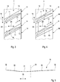
- the respective blade root 13 has, on a side 15 facing the gas path 12, which is located in the circumferential direction next to the blade 8, a curved end wall contour 16, which in FIG FIG. 1 is indicated and in FIG. 5 is reproduced.
- the intermediate pieces 14 likewise have an outer side 17 facing the gas path 12, on which the intermediate pieces 14 likewise each have such a curved end wall contour 16.
- the curvature of the end wall contour 16 extends along the gas path 12, that is, substantially along the axial direction, which is defined by the rotation axis 6.
- at least the intermediate pieces 14 may also be curved in the circumferential direction, namely corresponding to a radius 34 of the rotor 5.
- the end wall contours 16 of the outer sides 15 of the blade roots 13 on the one hand and the outer sides 17 of the intermediate pieces 14 on the other hand have the same geometric shape.
- flush transitions on the adjoining outer sides 15, 17 of the blade roots 13 and the intermediate pieces 14 can thereby be realized.
- the outer sides 15 of the blade roots 13 and the outer sides 17 of the intermediate pieces 14 as in FIG. 2 recognizable radially adjacent to each other in the circumferential direction.
- the end wall contours 16 of the outer sides 15 of the blade roots 13 and the end wall contours 16 of the outer sides 17 of the intermediate pieces 14 are configured axially symmetrical.
- the respective profile results as in the FIGS. 1 and 5 by a longitudinal section containing the axis of rotation 6.
- the end wall contours 16 are thus designed rotationally symmetrical. Only at the respective blade 8, a three-dimensional transition from the blade root 13 to the blade 11 may be appropriate.
- the blade roots 13 and the intermediate pieces 14 are configured symmetrically, so that it is fundamentally possible to arrange the blade roots 13 and the intermediate pieces 14 rotated by 180 ° in the receiving groove 10.
- the rotation by 180 ° refers to a rotation about the radial direction in the FIGS. 3 and 4 is perpendicular to the plane of the drawing.
- the blade roots have 13 in Fig. 3 a width 18 which remains constant in the flow direction 21.
- the intermediate pieces 14 here have a width 22 which remains constant in the flow direction 21.
- FIG. 1 has the receiving groove 10 at its mutually axially opposite groove walls 23 radially inwardly directed support contours 24.
- the intermediate pieces 14 have according to FIG. 2 at in the axial direction 20 facing away from each other ends 25 radially outwardly directed support contours 26 which are complementary to the support contours 24 of the receiving groove 10 are formed.
- the support contours 26 of the intermediate pieces 14 can be supported radially on the support contours 24 of the receiving groove 10.
- FIG. 2 have the blade roots 13 on its inner side 27, which faces away from the gas path 12 and from the outer side 15 of the blade root 13, in the circumferential direction 19 projecting paragraphs 28 on.
- each blade root 13 expediently two such paragraphs 28 are provided, which protrude at two opposite end faces in the circumferential direction 19 of the respective end face.
- these paragraphs 28 each engage under an inner side 29 of the adjacent intermediate piece 14, which faces away from the outer side 17 of the intermediate piece 14 or from the gas path 12.
- the paragraphs 28 are supported in the assembled state radially on the inner sides 29 of the adjacent intermediate pieces 14 from.
- Particularly advantageous is an embodiment in which the blades 8 are anchored exclusively indirectly via the intermediate pieces 14 on the rotor shaft 9 radially.
- the end wall contour 16 may be configured to have exactly two inflection points 30, thereby making it possible to form a concave camber 31 oriented toward the rotation axis 6 and to realize tangential transitions at the end portions 32 of the end wall contour 16.
- the curvature 31 is recognizable offset with respect to a geometric center 33 of the end wall contour 16 with respect to the axial direction 20 arranged, that is arranged eccentrically. In particular, the curvature 31 is thereby positioned shifted with respect to the center 33 to the inflow side.
Landscapes
- Engineering & Computer Science (AREA)
- Mechanical Engineering (AREA)
- General Engineering & Computer Science (AREA)
- Physics & Mathematics (AREA)
- Fluid Mechanics (AREA)
- Structures Of Non-Positive Displacement Pumps (AREA)
- Turbine Rotor Nozzle Sealing (AREA)
Abstract
Description
- Die vorliegende Erfindung betrifft einen Rotor für eine Turbomaschine, insbesondere einen Verdichterrotor oder einen Turbinenrotor einer Turbomaschine, zum Beispiel eine Gasturbine oder eine Dampfturbine, vorzugsweise einer Kraftwerksanlage. Außerdem betrifft die vorliegende Erfindung ein Verfahren zum Modernisieren einer Turbomaschine.
- Üblicherweise umfasst ein Rotor zumindest eine Laufschaufelreihe, die mehrere Laufschaufeln aufweist, die bezüglich einer Rotationsachse des Rotors in der Umfangsrichtung zueinander beabstandet angeordnet sind. Dabei stehen die Laufschaufeln ausgehend vom Rotor in einen Gaspfad vor. In diesem Gaspfad strömt im Betrieb der Turbomaschine ein Arbeitsgas. Ferner umfasst ein solcher Rotor typischerweise eine Rotorwelle, die für die jeweilige Laufschaufelreihe eine sich in Umfangsrichtung erstreckende Aufnahmenut aufweist, in welche die Laufschaufeln mit ihren Schaufelfüßen eingesetzt sind. Ferner können mehrere Zwischenstücke vorgesehen sein, die in der Aufnahmenut jeweils zwischen zwei benachbarten Laufschaufeln angeordnet sind.
- Die Laufschaufeln weisen außerdem jeweils ein Schaufelblatt auf, das vom zugehörigen Schaufelfuß, über den die jeweilige Laufschaufeln an der Rotorwelle befestigt ist, vom Rotor im Wesentlichen radial absteht und so in den Gaspfad hineinragt. Im Bereich eines dem Schaufelfuß zugeordneten inneren Endabschnitts kann insbesondere bei einem Verdichter eine Stabilisierung der Gasströmung im Betrieb der Turbomaschine durch eine spezielle Konturgebung an einer an das Schaufelblatt angrenzenden, dem Gaspfad ausgesetzten Außenseite des Rotors erzielt werden. Hierbei handelt es sich um eine den Gaspfad begrenzende Endwandkontur des Rotors, die insbesondere entlang des Gaspfads gewölbt sein kann. Dabei ist es grundsätzlich möglich, die Laufschaufeln an ihren Schaufelfüßen an einer dem Gaspfad zugewandten Außenseite in der Umfangsrichtung neben dem Schaufelblatt mit einer solchen gewölbten Endwandkontur auszustatten.
- Beispielsweise zeigen die Zeichnungen der
US 5 232 348 A und derUS 2 916 257 A gewölbte Endwandkonturen, wobei die gaspfadseitigen Endwände der Zwischenstücke bündig und stufenfrei in die Endwände der Schaufelfüße übergehen. Anstelle einer dem Gaspfad zugewandten konvexen Ausgestaltung der Wölbung kann auch eine geradlinige Ausgestaltung vorgesehen sein. - Hier setzt die vorliegende Erfindung an. Die Erfindung beschäftigt sich mit dem Problem, für einen Rotor der eingangs genannten Art eine verbesserte Ausführungsform anzugeben, die sich insbesondere dadurch auszeichnet, dass die Endwandkontur leichter herstellbar ist. Dabei soll auch eine vergleichsweise preiswerte Modernisierung bestehender Turbomaschinen ermöglicht werden.
- Dieses Problem wird erfindungsgemäß durch den Gegenstand des unabhängigen Anspruchs gelöst. Vorteilhafte Ausführungsformen sind Gegenstand der abhängigen Ansprüche.
- Die jeweilige Endwandkontur kann in einem Axialschnitt entsprechend einer vorteilhaften Ausführungsform genau zwei Wendepunkte aufweisen und insbesondere an ihren axialen Enden tangential in die Außenseite der Rotorwelle übergehen. Zusätzlich oder alternativ kann die jeweilige Endwandkontur konkav gewölbt sein. Zusätzlich oder alternativ ist es möglich, dass bei der jeweiligen Endwandkontur die Wölbung entlang des Gaspfads außermittig angeordnet ist, wobei sie insbesondere bei einem Verdichter zur Anströmseite hin verschoben sein kann.
- Ein erfindungsgemäßer Verdichter bzw. eine erfindungsgemäße Turbine ist mit einem Rotor der vorbeschriebenen Art ausgestattet und kann in einer Turbomaschine zur Anwendung kommen, beispielsweise in einer stationären Turbomaschine einer Kraftwerksanlage.
- Bei der Erfindung ist insbesondere vorgesehen, nicht nur die dem Gaspfad zugewandten Außenseiten der Schaufelfüße, sondern auch die dem Gaspfad zugewandte Außenseite der Zwischenstücke mit einer derartigen Endwandkontur auszustatten. Hierdurch gestaltet sich der Übergang von der Endwandkontur der Außenseite des jeweiligen Schaufelfußes zur Endwandkontur der Außenseite des jeweils benachbarten Zwischenstücks einfacher. Es ist daher insbesondere keine komplexe dreidimensionale Formgebung für die Endwandkontur am Schaufelfuß mehr erforderlich. Somit kann der Aufwand zum Herstellen der Endwandkonturen reduziert werden. Da erfindungsgemäß nun auch die Zwischenstücke mit einer solchen Endwandkontur versehen sind, ist es z.B. im Rahmen einer Modernisierung möglich, die Laufschaufeln und die Zwischenstücke auszutauschen, um eine bestehende Turbomaschine nachträglich mit der gewölbten Endwandkontur auszustatten.
- Entsprechend einer vorteilhaften Ausführungsform können die Endwandkonturen an den Außenseiten der Schaufelfüße und der Zwischenstücke gleich sein. Die Herstellung gleicher Endwandkonturen sowohl an den Schaufelfüßen als auch an den Zwischenstücken vermeidet komplexe dreidimensionale Übergänge, was die Herstellung der Endwandkonturen vereinfacht.
- Entsprechend einer besonders vorteilhaften Ausführungsform können die Endwandkonturen axial-symmetrisch ausgestaltet sein. Das bedeutet, dass die Endwandkonturen bezüglich der Rotationsachse drehsymmetrisch ausgestaltet sind. Mit anderen Worten, die jeweilige Endwandkontur ist in einer Schnittebene, welche die Rotationsachse enthält, in der Umfangsrichtung gleichbleibend bzw. konstant profiliert. Hierdurch ist es besonders einfach, die Endwandkonturen an den Außenseiten der Schaufelfüße und an den Außenseiten der Zwischenstücke anzubringen.
- Gemäß einer anderen vorteilhaften Ausführungsform können die Zwischenstücke und die Schaufelfüße in der Axialrichtung asymmetrisch ausgestaltet sein, derart, dass die Zwischenstücke nur in einer einzigen Montageposition ordnungsgemäß montierbar sind. Für den Fall, dass die gewölbten Endwandkonturen in der Axialrichtung asymmetrisch konfiguriert sind, vermeidet die vorstehend vorgeschlagene Bauform eine fehlerhafte Montage der Zwischenstücke, die zu einer erheblichen Beeinträchtigung der Umströmung der jeweiligen Laufschaufeln im Bereich des Schaufelfußes führen würde.
- Gemäß einer speziellen Ausführungsform kann die Aufnahmenut an sich axial gegenüberliegenden Nutwänden radial nach innen gerichtete Stützkonturen aufweisen, wobei die Zwischenstücke zu den Stützkonturen der Aufnahmenut komplementäre radial nach außen gerichtete Stützkonturen aufweisen, die sich im montierten Zustand radial an den Stützkonturen der Aufnahmenut abstützen. Hierdurch sind die Zwischenstücke in der Aufnahmenut radial nach außen durch intensiven Formschluss zwischen den aneinander anliegenden Stützkonturen fixiert. Um die Zwischenstücke in die jeweilige Aufnahmenut einführen zu können, kann die Rotorwelle in einer Axialebene geteilt sein.
- Entsprechend einer bevorzugten Weiterbildung können die Schaufelfüße an ihrer vom Gaspfad abgewandten bzw. von ihrer Außenseite abgewandten Innenseite in der Umfangsrichtung vorstehende Absätze aufweisen, die sich im montierten Zustand radial an einer von der jeweiligen Außenseite abgewandten Innenseite des jeweiligen benachbarten Zwischenstücks abstützen. Bei dieser Ausführungsform sind somit die Schaufelfüße mittelbar über die Zwischenstücke an der Rotorwelle radial festgelegt. Zusätzlich können die Schaufelfüße ebenso wie die Zwischenstücke Stützkonturen aufweisen, die mit den Stützkonturen der Aufnahmenut zusammenwirken.
- Bevorzugt ist jedoch eine Ausführungsform, bei der die Laufschaufeln ausschließlich mittelbar über die Zwischenstücke an der Rotorwelle radial befestigt sind. Hierdurch ist es besonders einfach möglich, für den Wartungsfall die Laufschaufeln radial aus der Aufnahmenut herauszuziehen, wenn hierzu wenigstens ein Zwischenstück aus der Aufnahmenut herausgenommen ist, so dass alle übrigen Zwischenstücke und Schaufelfüße innerhalb der Aufnahmenut in der Umfangsrichtung verschiebbar sind.
- Weitere wichtige Merkmale und Vorteile der Erfindung ergeben sich aus den Unteransprüchen, aus den Zeichnungen und aus der zugehörigen Figurenbeschreibung anhand der Zeichnungen.
- Es versteht sich, dass die vorstehend genannten und die nachstehend noch zu erläuternden Merkmale nicht nur in der jeweils angegebenen Kombination, sondern auch in anderen Kombinationen oder in Alleinstellung verwendbar sind, ohne den Rahmen der vorliegenden Erfindung zu verlassen.
- Bevorzugte Ausführungsbeispiele der Erfindung sind in den Zeichnungen dargestellt und werden in der nachfolgenden Beschreibung näher erläutert, wobei sich gleiche Bezugszeichen auf gleiche oder ähnliche oder funktional gleiche Bauteile beziehen.
- Es zeigen, jeweils schematisch,
- Fig. 1
- einen Längsschnitt durch eine Turbomaschine im Bereich eines Rotors,
- Fig. 2
- eine isometrische Ansicht auf einen Umfangsabschnitt einer Laufschaufelreihe des Rotors,
- Fig. 3
- eine radiale Draufsicht auf einen Umfangsabschnitt der Laufschaufelreihe,
- Fig. 4
- eine Draufsicht wie in
Fig. 3 , jedoch bei einer anderen Ausführungsform, - Fig. 5
- eine Endwandkontur im Längsschnitt.
- Entsprechend
Figur 1 umfasst eine Turbomaschine 1, bei der es sich um eine Gasturbinenanlage oder um eine Dampfturbinenanlage eines Kraftwerks zur Stromgewinnung handeln kann, einen Verdichter 2 oder eine Turbine 3 mit einem Stator 4, in dem ein Rotor 5 um eine Rotationsachse 6 drehbar gelagert ist. Der Rotor 5 weist zumindest eine Laufschaufelreihe 7 auf, die mehrere Laufschaufeln 8 besitzt, die bezüglich der Rotationsachse 6 in der Umfangsrichtung zueinander benachbart angeordnet sind. Die inFigur 1 dargestellte, die Rotationsachse 6 repräsentierende strichpunktierte Linie ist nicht maßstäblich zu verstehen, sondern nur zur Andeutung der Orientierung der Rotationsachse 6. - Der Rotor 5 weist ferner eine Rotorwelle 9 auf, in welche für die jeweilige Laufschaufelreihe 7 eine sich in der Umfangsrichtung ringförmig erstreckende Aufnahmenut 10 eingearbeitet ist. Die Laufschaufeln 8 besitzen jeweils ein Schaufelblatt 11, das im eingebauten Zustand in einen in
Figur 1 durch eine strichpunktierte Linie angedeuteten Gaspfad 12 hineinragt, und einen Schaufelfuß 13, der in die Aufnahmenut 10 eingesetzt ist. Insoweit ist der Schaufelfuß 13 baulich in die Rotorwelle 9 integriert. Ferner umfasst der Rotor 5 gemäßFigur 2 mehrere Zwischenstücke 14, die ebenfalls in die Aufnahmenut 10 eingesetzt sind und dabei jeweils zwischen zwei benachbarten Laufschaufeln 8 bzw. zwischen zwei benachbarten Schaufelfüßen 13 angeordnet sind. Innerhalb der jeweiligen Laufschaufelreihe 7 bzw. innerhalb der zugehörigen Aufnahmenut 10 wechseln sich somit Zwischenstücke 14 und Laufschaufeln 8 bzw. Schaufelfüße 13 ab. - Der jeweilige Schaufelfuß 13 weist an einer dem Gaspfad 12 zugewandten Außenseite 15, die sich in der Umfangsrichtung neben dem Schaufelblatt 8 befindet, eine gewölbte Endwandkontur 16 auf, die in
Figur 1 angedeutet ist und inFigur 5 wiedergegeben ist. Die Zwischenstücke 14 besitzen ebenfalls eine dem Gaspfad 12 zugewandte Außenseite 17, an der die Zwischenstücke 14 ebenfalls jeweils eine derartige gewölbte Endwandkontur 16 aufweisen. Die Wölbung der Endwandkontur 16 erstreckt sich dabei entlang des Gaspfads 12, also im Wesentlichen entlang der Axialrichtung, die durch die Rotationsachse 6 definiert ist. Darüber hinaus können zumindest die Zwischenstücke 14 auch in der Umfangsrichtung gewölbt sein, nämlich entsprechend einem Radius 34 des Rotors 5. - Besonders vorteilhaft ist es dabei, wenn die Endwandkonturen 16 der Außenseiten 15 der Schaufelfüße 13 einerseits und der Außenseiten 17 der Zwischenstücke 14 andererseits geometrisch gleich geformt sind. Insbesondere lassen sich dadurch bündige Übergänge an den aneinandergrenzenden Außenseiten 15, 17 der Schaufelfüße 13 und der Zwischenstücke 14 realisieren. Beispielsweise können die Außenseiten 15 der Schaufelfüße 13 und die Außenseiten 17 der Zwischenstücke 14 wie in
Figur 2 erkennbar radial bündig in der Umfangsrichtung aneinandergrenzen. - Von besonderem Interesse ist eine Ausführungsform, bei welcher die Endwandkonturen 16 der Außenseiten 15 der Schaufelfüße 13 und die Endwandkonturen 16 der Außenseiten 17 der Zwischenstücke 14 axial-symmetrisch ausgestaltet sind. Das bedeutet, dass die Endwandkonturen 16 in der Umfangsrichtung ein konstant bleibendes Profil aufweisen. Das jeweilige Profil ergibt sich dabei wie in den
Figuren 1 und5 durch einen Längsschnitt, der die Rotationsachse 6 enthält. Bezüglich dieser Rotationsachse 6 sind die Endwandkonturen 16 somit drehsymmetrisch ausgestaltet. Lediglich an der jeweiligen Laufschaufel 8 kann ein dreidimensionaler Übergang vom Schaufelfuß 13 zum Schaufelblatt 11 zweckmäßig sein. - Bei der in
Figur 3 gezeigten Ausführungsform sind die Schaufelfüße 13 und die Zwischenstücke 14 symmetrisch ausgestaltet, so dass es grundsätzlich möglich ist, die Schaufelfüße 13 und die Zwischenstücke 14 um 180° verdreht in der Aufnahmenut 10 anzuordnen. Die Verdrehung um 180° bezieht sich dabei auf eine Drehung um die Radialrichtung, die in denFiguren 3 und 4 senkrecht zur Zeichnungsebene steht. - Sofern die Endwandkonturen 16 wie in den
Figuren 1 und5 angedeutet bezüglich der Axialrichtung asymmetrisch ausgestaltet sind, führt eine verkehrte Montage der Zwischenstücke 14 zu einer signifikanten Verschlechterung der Umströmung der Schaufelblätter 11 im Bereich der Schaufelfüße 13. Eine falsche Montage der Laufschaufeln 8 ist dabei nahezu ausgeschlossen, da dies aufgrund der Asymmetrie der Schaufelblätter 11 sofort offensichtlich ist. Zur Vermeidung einer Falschmontage der Zwischenstücke 14 kann gemäßFigur 4 vorgesehen sein, die Zwischenstücke 14 und die Schaufelfüße 13 asymmetrisch zu konfigurieren, derart, dass die Zwischenstücke 14 nur in einer einzigen, vorgegebenen Montageposition ordnungsgemäß montierbar sind. Erreicht wird dies im Beispiel derFigur 4 rein exemplarisch durch eine Keilform der Zwischenstücke 14 bezüglich ihrer axialen Erstreckung sowie durch eine dazu komplementäre Keilform der Schaufelfüße 13 ebenfalls hinsichtlich der axialen Erstreckung. Beispielsweise kann eine Breite 18 der Schaufelfüße 13, die in der in denFiguren 3 und 4 durch einen Doppelpfeil angedeuteten Umfangsrichtung 19 gemessen wird, in der in denFiguren 3 und 4 sowie inFigur 1 durch einen Doppelpfeil angedeuteten Axialrichtung 20 in der in denFiguren 3 und 4 durch einen Richtungspfeil angedeuteten Strömungsrichtung 21 des Arbeitsgases zunehmen, während eine in der Umfangsrichtung 19 gemessene Breite 22 der Zwischenstücke 14 in der Axialrichtung 20 in der Strömungsrichtung 21 entsprechend abnimmt. Im Unterschied dazu besitzen die Schaufelfüße 13 inFig. 3 eine in der Strömungsrichtung 21 konstant bleibende Breite 18. Ebenso besitzen die Zwischenstücke 14 hier eine in der Strömungsrichtung 21 konstant bleibende Breite 22. - Durch die asymmetrische Formgebung der Zwischenstücke 14 und der Schaufelfüße 13 würde bei einer Fehlmontage zwangsläufig eine sichtbare Lücke zwischen Schaufelfuß 13 und Zwischenstück 14 verbleiben, so dass die Falschmontage sofort bemerkt werden kann.
- Gemäß
Figur 1 weist die Aufnahmenut 10 an ihren aneinander axial gegenüberliegenden Nutwänden 23 radial nach innen gerichtete Stützkonturen 24 auf. Die Zwischenstücke 14 besitzen gemäßFigur 2 an in der Axialrichtung 20 voneinander abgewandten Enden 25 radial nach außen gerichtete Stützkonturen 26, die komplementär zu den Stützkonturen 24 der Aufnahmenut 10 geformt sind. - Im montierten Zustand können sich die Stützkonturen 26 der Zwischenstücke 14 radial an den Stützkonturen 24 der Aufnahmenut 10 abstützen. Gemäß
Figur 2 weisen die Schaufelfüße 13 an ihrer Innenseite 27, die vom Gaspfad 12 bzw. von der Außenseite 15 des Schaufelfußes 13 abgewandt ist, in der Umfangsrichtung 19 vorstehende Absätze 28 auf. Dabei sind je Schaufelfuß 13 zweckmäßig zwei derartige Absätze 28 vorgesehen, die an zwei voneinander abgewandten Stirnseiten in der Umfangsrichtung 19 von der jeweiligen Stirnseite vorstehen. Im montierten Zustand untergreifen diese Absätze 28 jeweils eine Innenseite 29 des benachbarten Zwischenstücks 14, die von der Außenseite 17 des Zwischenstücks 14 bzw. vom Gaspfad 12 abgewandt ist. Ferner stützen sich die genannten Absätze 28 im montierten Zustand radial an den Innenseiten 29 der benachbarten Zwischenstücke 14 ab. Besonders vorteilhaft ist dabei eine Ausführungsform, bei der die Laufschaufeln 8 ausschließlich mittelbar über die Zwischenstücke 14 an der Rotorwelle 9 radial verankert sind. - Gemäß
Figur 5 kann die Endwandkontur 16 so konfiguriert sein, dass sie genau zwei Wendepunkte 30 aufweist, wodurch es möglich ist, eine zur Rotationsachse 6 hin orientierte konkave Wölbung 31 auszubilden sowie tangentiale Übergänge an den Endabschnitten 32 der Endwandkontur 16 zu realisieren. Die Wölbung 31 ist erkennbar bezüglich einer geometrischen Mitte 33 der Endwandkontur 16 bezüglich der Axialrichtung 20 versetzt angeordnet, also außermittig angeordnet. Insbesondere ist die Wölbung 31 dabei bezüglich der Mitte 33 zur Anströmseite hin verschoben positioniert. -
- 1
- Turbomaschine
- 2
- Verdichter
- 3
- Turbine
- 4
- Stator
- 5
- Rotor
- 6
- Rotationsachse
- 7
- Laufschaufelreihe
- 8
- Laufschaufel
- 9
- Rotorwelle
- 10
- Aufnahmenut
- 11
- Schaufelblatt
- 12
- Gaspfad
- 13
- Schaufelfuß
- 14
- Zwischenstück
- 15
- Außenseite von 13
- 16
- Endwandkontur
- 17
- Außenseite von 14
- 18
- Breite von 13
- 19
- Umfangsrichtung
- 20
- Axialrichtung
- 21
- Strömungsrichtung
- 22
- Breite von 14
- 23
- Nutwand
- 24
- Stützstruktur von 10
- 25
- Ende von 14
- 26
- Stützstruktur von 14
- 27
- Innenseite von 13
- 28
- Absatz
- 29
- Innenseite von 14
- 30
- Wendepunkt
- 31
- Wölbung
- 32
- Endabschnitt
- 33
- Mitte
Claims (11)
- Rotor für eine Turbomaschine (1),- mit wenigstens einer Laufschaufelreihe (7), die mehrere Laufschaufeln (8) aufweist, die bezüglich einer Rotationsachse (6) des Rotors (5) in der Umfangsrichtung (19) zueinander benachbart angeordnet sind,- mit wenigstens einer Rotorwelle (9), die für die jeweilige Laufschaufelreihe (7) eine sich in Umfangsrichtung (19) erstreckende Aufnahmenut (10) aufweist, in welche die Laufschaufeln (8) mit ihren Schaufelfüßen (13) eingesetzt sind,- mit mehreren Zwischenstücken (14), die in der Aufnahmenut (10) jeweils zwischen zwei benachbarten Laufschaufeln (8) angeordnet sind,- wobei die Laufschaufeln (8) an ihren Schaufelfüßen (13) an einer Außenseite (15) jeweils eine gewölbte Endwandkontur (16) in der Umfangsrichtung (19) neben einem Schaufelblatt (11) der jeweiligen Laufschaufel (8) aufweisen,- wobei die Zwischenstücke (14) an einer Außenseite (17) ebenfalls jeweils eine gewölbte Endwandkontur (17) aufweisen,- wobei die Außenseiten (15, 17) der Schaufelfüße (13) und der Zwischenstücke (14) radial bündig in der Umfangsrichtung (19) aneinandergrenzen,dadurch gekennzeichnet,
dass die Einwandkontur (16) in einer axialen Schnittebene des Rotors eine konkave Wölbung (31) aufweist. - Rotor nach Anspruch 1,
dadurch gekennzeichnet,
dass die Endwandkonturen (16) zwei Wendepunkte (30) aufweist. - Rotor nach Anspruch 1 oder 2,
dadurch gekennzeichnet,
dass die Wölbung (31) zur Anströmseite oder zur Abströmseite verschoben angeordnet ist. - Rotor nach Anspruch 1 oder 2,
dadurch gekennzeichnet,
dass die Endwandkonturen (16) axial-symmetrisch ausgestaltet sind. - Rotor nach einem der Ansprüche 1 bis 4,
dadurch gekennzeichnet,
dass die Endwandkonturen (16) an den Außenseiten (15, 17) der Schaufelfüße (13) und der Zwischenstücke (14) gleich sind. - Rotor nach einem der Ansprüche 1 bis 5,
dadurch gekennzeichnet,
dass die Zwischenstücke (14) und die Schaufelfüße (13) asymmetrisch sind, so dass die Zwischenstücke (14) nur in einer Montageposition ordnungsgemäß montierbar sind. - Rotor nach einem der Ansprüche 1 bis 6,
dadurch gekennzeichnet,
dass die Aufnahmenut (10) an ihren Nutwänden (23) radial nach innen gerichtete Stützkonturen (24) aufweist, wobei die Zwischenstücke (14) zu den Stützkonturen (24) der Aufnahmenut (10) komplementäre, radial nach außen gerichtete Stützkonturen (26) aufweisen, die sich im montierten Zustand radial an den Stützkonturen (24) der Aufnahmenut (10) abstützen. - Rotor nach Anspruch 7,
dadurch gekennzeichnet,
dass die Schaufelfüße (13) an ihrer Innenseite (27) in der Umfangsrichtung (19) vorstehende Absätze (28) aufweisen, die sich im montierten Zustand radial an einer Innenseite (29) des jeweils benachbarten Zwischenstücks (14) abstützen. - Rotor nach Anspruch 8,
dadurch gekennzeichnet,
dass die Laufschaufeln (8) ausschließlich mittelbar über die Zwischenstücke (14) an der Rotorwelle (9) radial befestigt sind. - Verdichter oder Turbine für eine Turbomaschine (1) mit einem Rotor (5) nach einem der Ansprüche 1 bis 9.
- Verfahren zum Modernisieren eines Rotors (5) einer Turbomaschine (1), insbesondere eines Verdichters (2) oder einer Turbine (3), wobei der Rotor (5) umfasst wenigstens eine Laufschaufelreihe (7), die mehrere Laufschaufeln (8) aufweist, die bezüglich einer Rotationsachse (6) des Rotors (5) in der Umfangsrichtung (19) zueinander benachbart angeordnet sind, wenigstens eine Rotorwelle (9), die für die jeweilige Laufschaufelreihe (7) eine sich in Umfangsrichtung (19) erstreckende Aufnahmenut (10) aufweist, in welche die Laufschaufeln (8) mit ihren Schaufelfüßen (13) eingesetzt sind, mit mehreren Zwischenstücken (14), die in der Aufnahmenut (10) jeweils zwischen zwei benachbarten Laufschaufeln (8) angeordnet sind,- bei dem die Laufschaufeln (8) gegen Laufschaufeln (8) ausgetauscht werden, die an ihren Schaufelfüßen (13) an einer Außenseite (15) jeweils eine gewölbte Endwandkontur (16) in der Umfangsrichtung (19) neben einem Schaufelblatt (11) der jeweiligen Laufschaufel (8) aufweisen,- bei dem die Zwischenstücke (14) gegen Zwischenstücke (14) ausgetauscht werden, die an ihrer Außenseite (17) ebenfalls jeweils eine gewölbte Endwandkontur (17) aufweisen.
Priority Applications (1)
| Application Number | Priority Date | Filing Date | Title |
|---|---|---|---|
| HRP20160587TT HRP20160587T1 (hr) | 2011-03-31 | 2016-05-31 | Rotor za turbostroj i odgovarajući postupak nadogradnje |
Applications Claiming Priority (1)
| Application Number | Priority Date | Filing Date | Title |
|---|---|---|---|
| CH00583/11A CH704825A1 (de) | 2011-03-31 | 2011-03-31 | Turbomaschinenrotor. |
Publications (2)
| Publication Number | Publication Date |
|---|---|
| EP2505784A1 true EP2505784A1 (de) | 2012-10-03 |
| EP2505784B1 EP2505784B1 (de) | 2016-03-02 |
Family
ID=43857690
Family Applications (1)
| Application Number | Title | Priority Date | Filing Date |
|---|---|---|---|
| EP12162535.4A Active EP2505784B1 (de) | 2011-03-31 | 2012-03-30 | Rotor für eine Turbomaschine und zugehöriges Modernisierungsverfahren |
Country Status (9)
| Country | Link |
|---|---|
| US (1) | US8915716B2 (de) |
| EP (1) | EP2505784B1 (de) |
| JP (1) | JP5875439B2 (de) |
| CN (1) | CN102733858B (de) |
| AU (1) | AU2012201556B2 (de) |
| CH (1) | CH704825A1 (de) |
| HR (1) | HRP20160587T1 (de) |
| MY (1) | MY165413A (de) |
| RU (1) | RU2544019C2 (de) |
Cited By (2)
| Publication number | Priority date | Publication date | Assignee | Title |
|---|---|---|---|---|
| FR3014942A1 (fr) * | 2013-12-18 | 2015-06-19 | Snecma | Aube, roue a aubes et turbomachine ; procede de fabrication de l'aube |
| GB2488864B (en) * | 2011-03-07 | 2016-05-04 | Alstom Technology Ltd | Rotor blade arrangement of a turbomachine |
Families Citing this family (4)
| Publication number | Priority date | Publication date | Assignee | Title |
|---|---|---|---|---|
| US9267386B2 (en) | 2012-06-29 | 2016-02-23 | United Technologies Corporation | Fairing assembly |
| US10344601B2 (en) | 2012-08-17 | 2019-07-09 | United Technologies Corporation | Contoured flowpath surface |
| RU2682217C1 (ru) * | 2018-03-30 | 2019-03-15 | Публичное акционерное общество "ОДК-Уфимское моторостроительное производственное объединение" (ПАО "ОДК-УМПО") | Рабочее колесо ротора компрессора газотурбинного двигателя |
| JP7162514B2 (ja) * | 2018-12-07 | 2022-10-28 | 三菱重工業株式会社 | 軸流式ターボ機械及びその翼 |
Citations (2)
| Publication number | Priority date | Publication date | Assignee | Title |
|---|---|---|---|---|
| US2916257A (en) | 1953-12-30 | 1959-12-08 | Gen Electric | Damping turbine buckets |
| US5232346A (en) * | 1992-08-11 | 1993-08-03 | General Electric Company | Rotor assembly and platform spacer therefor |
Family Cites Families (14)
| Publication number | Priority date | Publication date | Assignee | Title |
|---|---|---|---|---|
| FR996967A (fr) | 1949-09-06 | 1951-12-31 | Rateau Soc | Perfectionnement aux aubages de turbomachines |
| US2669383A (en) | 1951-02-06 | 1954-02-16 | A V Roe Canada Ltd | Rotor blade |
| BE540433A (de) | 1954-08-12 | |||
| US4878811A (en) | 1988-11-14 | 1989-11-07 | United Technologies Corporation | Axial compressor blade assembly |
| US5397215A (en) * | 1993-06-14 | 1995-03-14 | United Technologies Corporation | Flow directing assembly for the compression section of a rotary machine |
| DE19650656C1 (de) * | 1996-12-06 | 1998-06-10 | Mtu Muenchen Gmbh | Turbomaschine mit transsonischer Verdichterstufe |
| RU2136973C1 (ru) * | 1998-03-26 | 1999-09-10 | Акционерное общество "Турбомоторный завод" | Устройство отборов воздуха из осевого компрессора |
| GB9823840D0 (en) * | 1998-10-30 | 1998-12-23 | Rolls Royce Plc | Bladed ducting for turbomachinery |
| EP1124038A1 (de) | 2000-02-09 | 2001-08-16 | Siemens Aktiengesellschaft | Turbinenschaufelanordnung |
| US6561761B1 (en) * | 2000-02-18 | 2003-05-13 | General Electric Company | Fluted compressor flowpath |
| US6669445B2 (en) | 2002-03-07 | 2003-12-30 | United Technologies Corporation | Endwall shape for use in turbomachinery |
| US7300253B2 (en) * | 2005-07-25 | 2007-11-27 | Siemens Aktiengesellschaft | Gas turbine blade or vane and platform element for a gas turbine blade or vane ring of a gas turbine, supporting structure for securing gas turbine blades or vanes arranged in a ring, gas turbine blade or vane ring and the use of a gas turbine blade or vane ring |
| EP2045444B1 (de) | 2007-10-01 | 2015-11-18 | Alstom Technology Ltd | Laufschaufel, Verfahren zur Herstellung einer Laufschaufel, sowie Verdichter mit einer solchen Laufschaufel |
| US8459956B2 (en) * | 2008-12-24 | 2013-06-11 | General Electric Company | Curved platform turbine blade |
-
2011
- 2011-03-31 CH CH00583/11A patent/CH704825A1/de not_active Application Discontinuation
-
2012
- 2012-03-15 AU AU2012201556A patent/AU2012201556B2/en active Active
- 2012-03-26 MY MYPI2012700116A patent/MY165413A/en unknown
- 2012-03-29 US US13/433,314 patent/US8915716B2/en not_active Expired - Fee Related
- 2012-03-29 JP JP2012076732A patent/JP5875439B2/ja not_active Expired - Fee Related
- 2012-03-30 EP EP12162535.4A patent/EP2505784B1/de active Active
- 2012-03-30 RU RU2012112418/06A patent/RU2544019C2/ru active
- 2012-03-30 CN CN201210103914.1A patent/CN102733858B/zh not_active Expired - Fee Related
-
2016
- 2016-05-31 HR HRP20160587TT patent/HRP20160587T1/hr unknown
Patent Citations (2)
| Publication number | Priority date | Publication date | Assignee | Title |
|---|---|---|---|---|
| US2916257A (en) | 1953-12-30 | 1959-12-08 | Gen Electric | Damping turbine buckets |
| US5232346A (en) * | 1992-08-11 | 1993-08-03 | General Electric Company | Rotor assembly and platform spacer therefor |
Cited By (4)
| Publication number | Priority date | Publication date | Assignee | Title |
|---|---|---|---|---|
| GB2488864B (en) * | 2011-03-07 | 2016-05-04 | Alstom Technology Ltd | Rotor blade arrangement of a turbomachine |
| FR3014942A1 (fr) * | 2013-12-18 | 2015-06-19 | Snecma | Aube, roue a aubes et turbomachine ; procede de fabrication de l'aube |
| WO2015092234A1 (fr) * | 2013-12-18 | 2015-06-25 | Snecma | Aube, roue a aubes et turbomachine; procédé de fabrication de l'aube |
| US10669863B2 (en) | 2013-12-18 | 2020-06-02 | Safran Aircraft Engines | Blade, bladed wheel, turbomachine, and a method of manufacturing the blade |
Also Published As
| Publication number | Publication date |
|---|---|
| JP5875439B2 (ja) | 2016-03-02 |
| RU2012112418A (ru) | 2013-10-10 |
| US20120251325A1 (en) | 2012-10-04 |
| CN102733858B (zh) | 2015-09-09 |
| MY165413A (en) | 2018-03-21 |
| AU2012201556A1 (en) | 2012-10-18 |
| AU2012201556B2 (en) | 2015-07-23 |
| US8915716B2 (en) | 2014-12-23 |
| EP2505784B1 (de) | 2016-03-02 |
| HRP20160587T1 (hr) | 2016-07-01 |
| CH704825A1 (de) | 2012-10-15 |
| JP2012215175A (ja) | 2012-11-08 |
| CN102733858A (zh) | 2012-10-17 |
| RU2544019C2 (ru) | 2015-03-10 |
Similar Documents
| Publication | Publication Date | Title |
|---|---|---|
| EP3176370B1 (de) | Leitschaufelcluster für eine strömungsmaschine | |
| EP2505784B1 (de) | Rotor für eine Turbomaschine und zugehöriges Modernisierungsverfahren | |
| DE112006002658B4 (de) | Turbomaschinenschaufel | |
| WO2007012587A1 (de) | Gasturbinenschaufel und plattformelement für einen gasturbinenschaufelkranz, tragstruktur zu deren befestigung, gasturbinenschaufelkranz und seine verwendung | |
| EP2918778B1 (de) | Verfahren zum auslegen einer turbine | |
| DE102008025249A1 (de) | Sammelraum und Verfahren zur Fertigung | |
| EP2478186B1 (de) | Rotor einer Turbomaschine | |
| EP3428393B1 (de) | Laufrad einer strömungsmaschine | |
| EP2723988B1 (de) | Verfahren zum profilieren einer ersatzschaufel als ein ersatzteil für eine altschaufel für eine axialströmungsmaschine | |
| EP3287611A1 (de) | Gasturbine und verfahren zum aufhängen eines turbinen-leitschaufelsegments einer gasturbine | |
| EP3428402B1 (de) | Leitschaufelsegment mit gekrümmter entlastungsfuge | |
| EP1706597B1 (de) | Strömungsmaschine mit einem axial verschiebbaren rotor | |
| EP2871325A1 (de) | Innenring einer Strömungsmaschine und Leitrad | |
| EP3390784B1 (de) | Strömungsmaschine mit mehreren leitschaufelstufen und verfahren zur teilweisen demontage einer solchen strömungsmaschine | |
| EP3492701A1 (de) | Turbomaschinen-strömungskanal | |
| EP2787178B1 (de) | Leitschaufelanordnung | |
| EP2653658A1 (de) | Leitschaufelkranz für eine Axialströmungsmaschine und Verfahren zum Auslegen des Leitschaufelkranzes | |
| EP2474744A1 (de) | Ringförmiger Strömungskanal für einen Axialverdichter | |
| EP2730745A1 (de) | Schaufelanordnung für eine Turbomaschine | |
| EP2526263A2 (de) | Gehäusesystem für eine axialströmungsmaschine | |
| EP3628030A1 (de) | Verfahren zum instandhalten einer strömungsmaschine | |
| DE102007053135A1 (de) | Gasturbinenbauteil, insbesondere Flugtriebwerksbauteil bzw. Verdichterbauteil | |
| DE102010055435B4 (de) | Innendeckband einer Gasturbine sowie Verfahren zur Herstellung eines Innendeckbandes | |
| EP3536913A1 (de) | Innenring für eine turbomaschine und entsprechendes herstellungsverfahren | |
| EP2884052B1 (de) | Rotor für eine strömungsmaschine mit geschlossenem strömungskonturring und verfahren zur herstellung desselben |
Legal Events
| Date | Code | Title | Description |
|---|---|---|---|
| PUAI | Public reference made under article 153(3) epc to a published international application that has entered the european phase |
Free format text: ORIGINAL CODE: 0009012 |
|
| AK | Designated contracting states |
Kind code of ref document: A1 Designated state(s): AL AT BE BG CH CY CZ DE DK EE ES FI FR GB GR HR HU IE IS IT LI LT LU LV MC MK MT NL NO PL PT RO RS SE SI SK SM TR |
|
| AX | Request for extension of the european patent |
Extension state: BA ME |
|
| 17P | Request for examination filed |
Effective date: 20130402 |
|
| GRAP | Despatch of communication of intention to grant a patent |
Free format text: ORIGINAL CODE: EPIDOSNIGR1 |
|
| INTG | Intention to grant announced |
Effective date: 20150924 |
|
| GRAS | Grant fee paid |
Free format text: ORIGINAL CODE: EPIDOSNIGR3 |
|
| GRAA | (expected) grant |
Free format text: ORIGINAL CODE: 0009210 |
|
| AK | Designated contracting states |
Kind code of ref document: B1 Designated state(s): AL AT BE BG CH CY CZ DE DK EE ES FI FR GB GR HR HU IE IS IT LI LT LU LV MC MK MT NL NO PL PT RO RS SE SI SK SM TR |
|
| REG | Reference to a national code |
Ref country code: GB Ref legal event code: FG4D Free format text: NOT ENGLISH |
|
| REG | Reference to a national code |
Ref country code: AT Ref legal event code: REF Ref document number: 778205 Country of ref document: AT Kind code of ref document: T Effective date: 20160315 Ref country code: CH Ref legal event code: EP |
|
| REG | Reference to a national code |
Ref country code: FR Ref legal event code: PLFP Year of fee payment: 5 |
|
| REG | Reference to a national code |
Ref country code: IE Ref legal event code: FG4D Free format text: LANGUAGE OF EP DOCUMENT: GERMAN |
|
| REG | Reference to a national code |
Ref country code: DE Ref legal event code: R096 Ref document number: 502012006092 Country of ref document: DE |
|
| REG | Reference to a national code |
Ref country code: HR Ref legal event code: TUEP Ref document number: P20160587 Country of ref document: HR |
|
| REG | Reference to a national code |
Ref country code: NL Ref legal event code: FP |
|
| REG | Reference to a national code |
Ref country code: HR Ref legal event code: T1PR Ref document number: P20160587 Country of ref document: HR |
|
| REG | Reference to a national code |
Ref country code: LT Ref legal event code: MG4D |
|
| PG25 | Lapsed in a contracting state [announced via postgrant information from national office to epo] |
Ref country code: GR Free format text: LAPSE BECAUSE OF FAILURE TO SUBMIT A TRANSLATION OF THE DESCRIPTION OR TO PAY THE FEE WITHIN THE PRESCRIBED TIME-LIMIT Effective date: 20160603 Ref country code: FI Free format text: LAPSE BECAUSE OF FAILURE TO SUBMIT A TRANSLATION OF THE DESCRIPTION OR TO PAY THE FEE WITHIN THE PRESCRIBED TIME-LIMIT Effective date: 20160302 Ref country code: NO Free format text: LAPSE BECAUSE OF FAILURE TO SUBMIT A TRANSLATION OF THE DESCRIPTION OR TO PAY THE FEE WITHIN THE PRESCRIBED TIME-LIMIT Effective date: 20160602 Ref country code: ES Free format text: LAPSE BECAUSE OF FAILURE TO SUBMIT A TRANSLATION OF THE DESCRIPTION OR TO PAY THE FEE WITHIN THE PRESCRIBED TIME-LIMIT Effective date: 20160302 |
|
| RAP2 | Party data changed (patent owner data changed or rights of a patent transferred) |
Owner name: GENERAL ELECTRIC TECHNOLOGY GMBH |
|
| PG25 | Lapsed in a contracting state [announced via postgrant information from national office to epo] |
Ref country code: SE Free format text: LAPSE BECAUSE OF FAILURE TO SUBMIT A TRANSLATION OF THE DESCRIPTION OR TO PAY THE FEE WITHIN THE PRESCRIBED TIME-LIMIT Effective date: 20160302 Ref country code: PL Free format text: LAPSE BECAUSE OF FAILURE TO SUBMIT A TRANSLATION OF THE DESCRIPTION OR TO PAY THE FEE WITHIN THE PRESCRIBED TIME-LIMIT Effective date: 20160302 Ref country code: BE Free format text: LAPSE BECAUSE OF NON-PAYMENT OF DUE FEES Effective date: 20160331 Ref country code: LV Free format text: LAPSE BECAUSE OF FAILURE TO SUBMIT A TRANSLATION OF THE DESCRIPTION OR TO PAY THE FEE WITHIN THE PRESCRIBED TIME-LIMIT Effective date: 20160302 Ref country code: RS Free format text: LAPSE BECAUSE OF FAILURE TO SUBMIT A TRANSLATION OF THE DESCRIPTION OR TO PAY THE FEE WITHIN THE PRESCRIBED TIME-LIMIT Effective date: 20160302 Ref country code: LT Free format text: LAPSE BECAUSE OF FAILURE TO SUBMIT A TRANSLATION OF THE DESCRIPTION OR TO PAY THE FEE WITHIN THE PRESCRIBED TIME-LIMIT Effective date: 20160302 |
|
| REG | Reference to a national code |
Ref country code: NL Ref legal event code: HC Owner name: GENERAL ELECTRIC TECHNOLOGY GMBH; CH Free format text: DETAILS ASSIGNMENT: VERANDERING VAN EIGENAAR(S), VERANDERING VAN NAAM VAN DE EIGENAAR(S); FORMER OWNER NAME: ALSTOM TECHNOLOGY LTD Effective date: 20160623 |
|
| REG | Reference to a national code |
Ref country code: DE Ref legal event code: R082 Ref document number: 502012006092 Country of ref document: DE Representative=s name: RUEGER | ABEL PATENT- UND RECHTSANWAELTE, DE Ref country code: DE Ref legal event code: R082 Ref document number: 502012006092 Country of ref document: DE Representative=s name: RUEGER ABEL PATENTANWAELTE PARTGMBB, DE Ref country code: DE Ref legal event code: R082 Ref document number: 502012006092 Country of ref document: DE Representative=s name: RUEGER, BARTHELT & ABEL, DE Ref country code: DE Ref legal event code: R081 Ref document number: 502012006092 Country of ref document: DE Owner name: GENERAL ELECTRIC TECHNOLOGY GMBH, CH Free format text: FORMER OWNER: ALSTOM TECHNOLOGY LTD., BADEN, CH Ref country code: DE Ref legal event code: R082 Ref document number: 502012006092 Country of ref document: DE Representative=s name: RUEGER ABEL PATENT- UND RECHTSANWAELTE, DE |
|
| PG25 | Lapsed in a contracting state [announced via postgrant information from national office to epo] |
Ref country code: IS Free format text: LAPSE BECAUSE OF FAILURE TO SUBMIT A TRANSLATION OF THE DESCRIPTION OR TO PAY THE FEE WITHIN THE PRESCRIBED TIME-LIMIT Effective date: 20160702 Ref country code: EE Free format text: LAPSE BECAUSE OF FAILURE TO SUBMIT A TRANSLATION OF THE DESCRIPTION OR TO PAY THE FEE WITHIN THE PRESCRIBED TIME-LIMIT Effective date: 20160302 |
|
| REG | Reference to a national code |
Ref country code: CH Ref legal event code: PL |
|
| PG25 | Lapsed in a contracting state [announced via postgrant information from national office to epo] |
Ref country code: SK Free format text: LAPSE BECAUSE OF FAILURE TO SUBMIT A TRANSLATION OF THE DESCRIPTION OR TO PAY THE FEE WITHIN THE PRESCRIBED TIME-LIMIT Effective date: 20160302 Ref country code: SM Free format text: LAPSE BECAUSE OF FAILURE TO SUBMIT A TRANSLATION OF THE DESCRIPTION OR TO PAY THE FEE WITHIN THE PRESCRIBED TIME-LIMIT Effective date: 20160302 Ref country code: PT Free format text: LAPSE BECAUSE OF FAILURE TO SUBMIT A TRANSLATION OF THE DESCRIPTION OR TO PAY THE FEE WITHIN THE PRESCRIBED TIME-LIMIT Effective date: 20160704 Ref country code: RO Free format text: LAPSE BECAUSE OF FAILURE TO SUBMIT A TRANSLATION OF THE DESCRIPTION OR TO PAY THE FEE WITHIN THE PRESCRIBED TIME-LIMIT Effective date: 20160302 Ref country code: CZ Free format text: LAPSE BECAUSE OF FAILURE TO SUBMIT A TRANSLATION OF THE DESCRIPTION OR TO PAY THE FEE WITHIN THE PRESCRIBED TIME-LIMIT Effective date: 20160302 |
|
| REG | Reference to a national code |
Ref country code: DE Ref legal event code: R097 Ref document number: 502012006092 Country of ref document: DE |
|
| REG | Reference to a national code |
Ref country code: IE Ref legal event code: MM4A |
|
| PG25 | Lapsed in a contracting state [announced via postgrant information from national office to epo] |
Ref country code: IT Free format text: LAPSE BECAUSE OF FAILURE TO SUBMIT A TRANSLATION OF THE DESCRIPTION OR TO PAY THE FEE WITHIN THE PRESCRIBED TIME-LIMIT Effective date: 20160302 |
|
| REG | Reference to a national code |
Ref country code: FR Ref legal event code: CD Owner name: ALSTOM TECHNOLOGY LTD, CH Effective date: 20161124 |
|
| PLBE | No opposition filed within time limit |
Free format text: ORIGINAL CODE: 0009261 |
|
| STAA | Information on the status of an ep patent application or granted ep patent |
Free format text: STATUS: NO OPPOSITION FILED WITHIN TIME LIMIT |
|
| REG | Reference to a national code |
Ref country code: HR Ref legal event code: PNAN Ref document number: P20160587 Country of ref document: HR Owner name: GENERAL ELECTRIC TECHNOLOGY GMBH, CH |
|
| PG25 | Lapsed in a contracting state [announced via postgrant information from national office to epo] |
Ref country code: LI Free format text: LAPSE BECAUSE OF NON-PAYMENT OF DUE FEES Effective date: 20160331 Ref country code: DK Free format text: LAPSE BECAUSE OF FAILURE TO SUBMIT A TRANSLATION OF THE DESCRIPTION OR TO PAY THE FEE WITHIN THE PRESCRIBED TIME-LIMIT Effective date: 20160302 Ref country code: IE Free format text: LAPSE BECAUSE OF NON-PAYMENT OF DUE FEES Effective date: 20160330 Ref country code: CH Free format text: LAPSE BECAUSE OF NON-PAYMENT OF DUE FEES Effective date: 20160331 |
|
| 26N | No opposition filed |
Effective date: 20161205 |
|
| PG25 | Lapsed in a contracting state [announced via postgrant information from national office to epo] |
Ref country code: SI Free format text: LAPSE BECAUSE OF FAILURE TO SUBMIT A TRANSLATION OF THE DESCRIPTION OR TO PAY THE FEE WITHIN THE PRESCRIBED TIME-LIMIT Effective date: 20160302 Ref country code: BG Free format text: LAPSE BECAUSE OF FAILURE TO SUBMIT A TRANSLATION OF THE DESCRIPTION OR TO PAY THE FEE WITHIN THE PRESCRIBED TIME-LIMIT Effective date: 20160602 |
|
| GBPC | Gb: european patent ceased through non-payment of renewal fee |
Effective date: 20160602 |
|
| REG | Reference to a national code |
Ref country code: FR Ref legal event code: PLFP Year of fee payment: 6 |
|
| PG25 | Lapsed in a contracting state [announced via postgrant information from national office to epo] |
Ref country code: GB Free format text: LAPSE BECAUSE OF NON-PAYMENT OF DUE FEES Effective date: 20160602 |
|
| PG25 | Lapsed in a contracting state [announced via postgrant information from national office to epo] |
Ref country code: MT Free format text: LAPSE BECAUSE OF FAILURE TO SUBMIT A TRANSLATION OF THE DESCRIPTION OR TO PAY THE FEE WITHIN THE PRESCRIBED TIME-LIMIT Effective date: 20160302 |
|
| REG | Reference to a national code |
Ref country code: HR Ref legal event code: ODRP Ref document number: P20160587 Country of ref document: HR Payment date: 20180313 Year of fee payment: 7 |
|
| REG | Reference to a national code |
Ref country code: FR Ref legal event code: PLFP Year of fee payment: 7 |
|
| REG | Reference to a national code |
Ref country code: AT Ref legal event code: MM01 Ref document number: 778205 Country of ref document: AT Kind code of ref document: T Effective date: 20170330 |
|
| PG25 | Lapsed in a contracting state [announced via postgrant information from national office to epo] |
Ref country code: CY Free format text: LAPSE BECAUSE OF FAILURE TO SUBMIT A TRANSLATION OF THE DESCRIPTION OR TO PAY THE FEE WITHIN THE PRESCRIBED TIME-LIMIT Effective date: 20160302 Ref country code: HU Free format text: LAPSE BECAUSE OF FAILURE TO SUBMIT A TRANSLATION OF THE DESCRIPTION OR TO PAY THE FEE WITHIN THE PRESCRIBED TIME-LIMIT; INVALID AB INITIO Effective date: 20120330 |
|
| PGFP | Annual fee paid to national office [announced via postgrant information from national office to epo] |
Ref country code: HR Payment date: 20180313 Year of fee payment: 7 |
|
| PG25 | Lapsed in a contracting state [announced via postgrant information from national office to epo] |
Ref country code: LU Free format text: LAPSE BECAUSE OF NON-PAYMENT OF DUE FEES Effective date: 20160330 Ref country code: MK Free format text: LAPSE BECAUSE OF FAILURE TO SUBMIT A TRANSLATION OF THE DESCRIPTION OR TO PAY THE FEE WITHIN THE PRESCRIBED TIME-LIMIT Effective date: 20160302 Ref country code: TR Free format text: LAPSE BECAUSE OF FAILURE TO SUBMIT A TRANSLATION OF THE DESCRIPTION OR TO PAY THE FEE WITHIN THE PRESCRIBED TIME-LIMIT Effective date: 20160302 Ref country code: MC Free format text: LAPSE BECAUSE OF FAILURE TO SUBMIT A TRANSLATION OF THE DESCRIPTION OR TO PAY THE FEE WITHIN THE PRESCRIBED TIME-LIMIT Effective date: 20160302 |
|
| PG25 | Lapsed in a contracting state [announced via postgrant information from national office to epo] |
Ref country code: AT Free format text: LAPSE BECAUSE OF NON-PAYMENT OF DUE FEES Effective date: 20170330 |
|
| PG25 | Lapsed in a contracting state [announced via postgrant information from national office to epo] |
Ref country code: AL Free format text: LAPSE BECAUSE OF FAILURE TO SUBMIT A TRANSLATION OF THE DESCRIPTION OR TO PAY THE FEE WITHIN THE PRESCRIBED TIME-LIMIT Effective date: 20160302 |
|
| REG | Reference to a national code |
Ref country code: HR Ref legal event code: PBON Ref document number: P20160587 Country of ref document: HR Effective date: 20190330 |
|
| PG25 | Lapsed in a contracting state [announced via postgrant information from national office to epo] |
Ref country code: HR Free format text: LAPSE BECAUSE OF NON-PAYMENT OF DUE FEES Effective date: 20190330 |
|
| PGFP | Annual fee paid to national office [announced via postgrant information from national office to epo] |
Ref country code: FR Payment date: 20210218 Year of fee payment: 10 |
|
| PG25 | Lapsed in a contracting state [announced via postgrant information from national office to epo] |
Ref country code: FR Free format text: LAPSE BECAUSE OF NON-PAYMENT OF DUE FEES Effective date: 20220331 |
|
| P01 | Opt-out of the competence of the unified patent court (upc) registered |
Effective date: 20230522 |
|
| PGFP | Annual fee paid to national office [announced via postgrant information from national office to epo] |
Ref country code: NL Payment date: 20260219 Year of fee payment: 15 |
|
| PGFP | Annual fee paid to national office [announced via postgrant information from national office to epo] |
Ref country code: DE Payment date: 20260219 Year of fee payment: 15 |