EP2505233B1 - Muscular toning device - Google Patents
Muscular toning device Download PDFInfo
- Publication number
- EP2505233B1 EP2505233B1 EP12002089.6A EP12002089A EP2505233B1 EP 2505233 B1 EP2505233 B1 EP 2505233B1 EP 12002089 A EP12002089 A EP 12002089A EP 2505233 B1 EP2505233 B1 EP 2505233B1
- Authority
- EP
- European Patent Office
- Prior art keywords
- cable
- handle
- exercise device
- hand
- handgrips
- Prior art date
- Legal status (The legal status is an assumption and is not a legal conclusion. Google has not performed a legal analysis and makes no representation as to the accuracy of the status listed.)
- Active
Links
- 230000003387 muscular Effects 0.000 title description 2
- 230000008878 coupling Effects 0.000 claims description 14
- 238000010168 coupling process Methods 0.000 claims description 14
- 238000005859 coupling reaction Methods 0.000 claims description 14
- 238000012549 training Methods 0.000 claims description 14
- 230000008859 change Effects 0.000 claims description 4
- 238000011161 development Methods 0.000 claims description 3
- 230000006378 damage Effects 0.000 claims description 2
- 238000005259 measurement Methods 0.000 claims description 2
- 230000003287 optical effect Effects 0.000 claims 1
- 230000001681 protective effect Effects 0.000 claims 1
- 238000009966 trimming Methods 0.000 description 24
- 210000000707 wrist Anatomy 0.000 description 16
- 210000003205 muscle Anatomy 0.000 description 6
- 230000007423 decrease Effects 0.000 description 5
- 210000003811 finger Anatomy 0.000 description 3
- 210000004247 hand Anatomy 0.000 description 3
- 230000004044 response Effects 0.000 description 3
- 238000004804 winding Methods 0.000 description 3
- 230000002411 adverse Effects 0.000 description 2
- 230000000694 effects Effects 0.000 description 2
- 238000009532 heart rate measurement Methods 0.000 description 2
- 210000003813 thumb Anatomy 0.000 description 2
- 230000008901 benefit Effects 0.000 description 1
- 230000036760 body temperature Effects 0.000 description 1
- 238000010276 construction Methods 0.000 description 1
- 230000003247 decreasing effect Effects 0.000 description 1
- 238000005265 energy consumption Methods 0.000 description 1
- 238000000605 extraction Methods 0.000 description 1
- 238000002372 labelling Methods 0.000 description 1
- 238000004519 manufacturing process Methods 0.000 description 1
- 238000012544 monitoring process Methods 0.000 description 1
- 230000004118 muscle contraction Effects 0.000 description 1
- 238000005457 optimization Methods 0.000 description 1
- 238000000554 physical therapy Methods 0.000 description 1
- 230000036316 preload Effects 0.000 description 1
- 238000002360 preparation method Methods 0.000 description 1
- 230000000284 resting effect Effects 0.000 description 1
- 238000001228 spectrum Methods 0.000 description 1
- 230000007103 stamina Effects 0.000 description 1
Images


Classifications
-
- A—HUMAN NECESSITIES
- A63—SPORTS; GAMES; AMUSEMENTS
- A63B—APPARATUS FOR PHYSICAL TRAINING, GYMNASTICS, SWIMMING, CLIMBING, OR FENCING; BALL GAMES; TRAINING EQUIPMENT
- A63B21/00—Exercising apparatus for developing or strengthening the muscles or joints of the body by working against a counterforce, with or without measuring devices
- A63B21/012—Exercising apparatus for developing or strengthening the muscles or joints of the body by working against a counterforce, with or without measuring devices using frictional force-resisters
- A63B21/018—Exercising apparatus for developing or strengthening the muscles or joints of the body by working against a counterforce, with or without measuring devices using frictional force-resisters including a rope or other flexible element moving relative to the surface of elements
-
- A—HUMAN NECESSITIES
- A63—SPORTS; GAMES; AMUSEMENTS
- A63B—APPARATUS FOR PHYSICAL TRAINING, GYMNASTICS, SWIMMING, CLIMBING, OR FENCING; BALL GAMES; TRAINING EQUIPMENT
- A63B21/00—Exercising apparatus for developing or strengthening the muscles or joints of the body by working against a counterforce, with or without measuring devices
- A63B21/0004—Exercising devices moving as a whole during exercise
- A63B21/00043—Exercising devices consisting of a pair of user interfaces connected by flexible elements, e.g. two handles connected by elastic bands
-
- A—HUMAN NECESSITIES
- A63—SPORTS; GAMES; AMUSEMENTS
- A63B—APPARATUS FOR PHYSICAL TRAINING, GYMNASTICS, SWIMMING, CLIMBING, OR FENCING; BALL GAMES; TRAINING EQUIPMENT
- A63B21/00—Exercising apparatus for developing or strengthening the muscles or joints of the body by working against a counterforce, with or without measuring devices
- A63B21/00058—Mechanical means for varying the resistance
- A63B21/00061—Replaceable resistance units of different strengths, e.g. for swapping
-
- A—HUMAN NECESSITIES
- A63—SPORTS; GAMES; AMUSEMENTS
- A63B—APPARATUS FOR PHYSICAL TRAINING, GYMNASTICS, SWIMMING, CLIMBING, OR FENCING; BALL GAMES; TRAINING EQUIPMENT
- A63B21/00—Exercising apparatus for developing or strengthening the muscles or joints of the body by working against a counterforce, with or without measuring devices
- A63B21/02—Exercising apparatus for developing or strengthening the muscles or joints of the body by working against a counterforce, with or without measuring devices using resilient force-resisters
- A63B21/023—Wound springs
- A63B21/025—Spiral springs with turns lying substantially in plane surfaces
-
- A—HUMAN NECESSITIES
- A63—SPORTS; GAMES; AMUSEMENTS
- A63B—APPARATUS FOR PHYSICAL TRAINING, GYMNASTICS, SWIMMING, CLIMBING, OR FENCING; BALL GAMES; TRAINING EQUIPMENT
- A63B21/00—Exercising apparatus for developing or strengthening the muscles or joints of the body by working against a counterforce, with or without measuring devices
- A63B21/15—Arrangements for force transmissions
- A63B21/151—Using flexible elements for reciprocating movements, e.g. ropes or chains
- A63B21/153—Using flexible elements for reciprocating movements, e.g. ropes or chains wound-up and unwound during exercise, e.g. from a reel
-
- A—HUMAN NECESSITIES
- A63—SPORTS; GAMES; AMUSEMENTS
- A63B—APPARATUS FOR PHYSICAL TRAINING, GYMNASTICS, SWIMMING, CLIMBING, OR FENCING; BALL GAMES; TRAINING EQUIPMENT
- A63B23/00—Exercising apparatus specially adapted for particular parts of the body
- A63B23/035—Exercising apparatus specially adapted for particular parts of the body for limbs, i.e. upper or lower limbs, e.g. simultaneously
- A63B23/03516—For both arms together or both legs together; Aspects related to the co-ordination between right and left side limbs of a user
- A63B23/03533—With separate means driven by each limb, i.e. performing different movements
- A63B23/03541—Moving independently from each other
Definitions
- the invention relates to a trimming device, which is designed to support the structure of the musculature of the human body, in particular the musculature of both shoulder areas and the areas of both arms - including the hands.
- Trimming machines for exercising the musculature of the human body are known and used in various designs, including trim devices that can be used while jogging or walking or even while sitting or standing by persons, around the muscles of the upper body, in particular the shoulder area including the arms. to train.
- a in this regard from the US 4,441,707 known isometric training belt is equipped with a hip belt, which serves as a guide for a non-stretchable, circulating around the user's waist rope.
- a hip belt which serves as a guide for a non-stretchable, circulating around the user's waist rope.
- the rope ends are alternately moved back and forth in response to swinging hand or arm movements, while the middle part of the rope is easily guided by the training belt around the hips.
- the resulting isometric muscle contractions cause voltage changes in the muscles involved, but no change in length, since the arm movements require little or no effort; the device is therefore only the extension of the exercise spectrum in a strength training.
- a disadvantage of the latter device is that the stretchy ropes are naturally subject to wear, which has decreasing, ie non-uniform expansion forces result.
- the ropes have a certain length and are designed for certain tensile forces, making them suitable only for users who have a matching arm length or a training condition corresponding to the tensile forces.
- Such a trimming device can only be used to a limited extent for several users with different training conditions and different stamina.
- a trimmer of other construction is from the US 5,618,249 A known. This consists of a hip belt on which a cable drum is provided in the back region for each arm or body side. Handles are attached to the cable ends leading out of the rope drums. In order for the cables to run from the user's body to his or her hands in certain directions, guide rods with guide rollers for the cables are also present in the back region of the hip belt. The preparation of such a trimmer is material and cost intensive, its handling is adversely affected due to the relatively large spatial structure and its weight.
- trimmer is out of the US Pat. No. 6,309,328 B1 known.
- this trimmer are within a housing which is provided on its outer side with a handle, a cable drum with a pre-wound rope and a device that makes it difficult to unwind the rope by a frictional force acting on the rope.
- a led out of the housing end of the rope can be attached to an object that rests relative to the trimmer, so that due to back and forth swinging hand or arm movements, the distance between the trimmer and object can be changed.
- the braking force is to be overcome, and it is also a restoring force generated, which causes the subsequent reeling of the rope rewinding the cable drum. The winding is not slowed down by the friction device.
- the present invention seeks to provide a trimming device, which is used by both persons of different constitution and different condition as well as the disadvantages of the prior art in terms of handling by the user no longer has. Incidentally, in this trimming device, the leverage applied to the wrist should be further reduced.
- a trimming device of the type mentioned above is equipped with two handles, one of which is designed to grip around with the right hand, the other for gripping with his left hand.
- each handle on a cable drum the drum axis is - when using the trimming device - both within the encompassing hand and is aligned substantially perpendicular to the palm of the hand.
- a cable is wound under pretension on each cable drum, led out of which a rope end of the handle and - when using the trimming device - with a predetermined position on the body of a user, preferably on Hull, mechanically firmly connected. Arm movements, which increase the distances between the handles and the attachment positions on the body, unwind the ropes by overcoming the bias, thereby requiring manual exercise supports the muscle structure.
- This training can be performed when the occupant is at rest relative to their environment, for example, standing, but also on the move, such as jogging.
- the use can be done for sports training, but also in connection with rehabilitation and physiotherapy.
- the trim device according to the invention is characterized inter alia by the fact that the axis of the respective cable drum is located within the encompassing hand, wherein they are each aligned perpendicular to the palm, and the outlet for the rope in both handles immediately laterally next to or immediately below one for the Plant of the handball provided outer surface of the handle is arranged.
- the generation of the bias under which the ropes are wound on the cable drums is provided by means of spiral springs, which are also arranged inside the handles.
- the coil springs produce when unwinding the ropes restoring forces, on the one hand correspond to the manually to be overcome pull-out forces, on the other hand cause the rope is rewound on the cable drum when reducing the distance between the respective handle and the attachment position of the rope on the body.
- the coil springs are functionally assigned to the cable drums so that their spring force counteracts the unwinding of the rope from the cable drum.
- means for varying the bias are provided under which the ropes are wound on the cable drums.
- These are, for example, designed as changing devices for the exchange of coil springs with different spring constants against each other.
- adjusting devices may be provided which are designed to increase or decrease the preload. This can be done in a conventional manner with adjusting wheels on the handles, with which the bias of the coil spring is either continuously or progressively variable.
- the spring force can be specified such that it is constant. This means that the force with which the rope is unwound from the rope drum is independent of the unwound rope length.
- the spring force can also be linearly increasing, so that the longer the unwound rope, the spring force and, accordingly, the extraction force necessary for unwinding increases all the more.
- the rope is wound on a conical drum.
- This cable drum preferably has rope grooves.
- the outer shapes of the two handles are designed unequal in that one handgrip is ergonomically adapted to the left hand, the other handgrip is ergonomically adapted to the right hand.
- the relevant features by which both handles differ are mirror images. Such are, for example the outlet openings for the ropes on the handles designed so that the rope exit direction is inclined in each case to the body.
- a plurality of different attachment positions on the trunk of the body are provided for the outgoing from the handles cable ends and provided for selection. This makes it possible to additionally vary the extension directions of the ropes from the handles.
- the attachment positions for example, by means of a belt to be attached to the torso, preferably at the hip, or a belt system to be placed around the upper body.
- Belt or belt system have at the attachment positions coupling elements for the cable ends, while at the cable ends to corresponding coupling elements are provided, which allow easy to manufacture and also to be loosened connection and may be formed, for example in the form of a bayonet lock or a hook-eye connection ,
- the coupling of the trimming device according to the invention is provided with means for measuring characteristics that characterize the training state of the body or the musculature, such as Seilauszugskraft- and training time measurement and their link to determine the energy consumption, pulse rate measurement and / or measurement of body temperature.
- a monitoring and optimization of training can be made.
- devices for the visually perceptible display and / or for storing the determined results may also be present.
- the handles of the trimming device according to the invention are provided with brackets to protect the back of the hand against impact injuries.
- at least one of the handles with a light source can continue be equipped, preferably in the dark to emit a light signal and thus in the open to prevent collisions with oncoming persons.
- the distance between the exit position of the rope from the handle on the one hand and the pivot point within the wrist area on the other hand, according to the invention further reduced in a trimming device of the type mentioned that the cable outlet opening is no longer below the edge of the hand and not in rectilinear Extension of the direction is arranged, in which the cable is unwound from the cable drum or wound up as a result of a restoring force on the cable drum, but the cable outlet opening is positioned laterally offset to this direction.
- the distance between the exit position of the rope from the handle and the wrist area could be further reduced and thus the disadvantage of the pull-out force on the wrist leverage effect can be further reduced.
- the lateral offset is achieved by deflection of the cable guide direction by means of rollers or sliders.
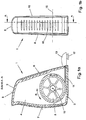
- Fig. 1 a handle 1 of the trimming device according to the invention is shown.
- Fig. 1a shows a lateral interior view in a section through the in Fig. 1b specified level AA.
- Fig. 1b shows the front view overlooking the narrow side of the same handle.
- the handle 1 by way of example of an upper housing part 2 and a lower housing part 3. Both housing parts 2, 3 enclose a cavity 4, in which a cable drum 5 is arranged.
- the outer contour is adapted from an ergonomic aspect of a gripping hand, wherein during use on the outer surface 6 of the handle 1 of the palm rests, while the outer surfaces 7 and 8 are enclosed with four fingers of the hand and the thumb can rest on the outer surface 9 or laterally on the outer surface 10 (see also FIG Fig. 1b ).
- Fig. 1a and Fig. 1b are arranged on the outer surface 6 arranged strip-shaped knobs 16, which give the surrounding fingers additional support.
- a cable 11 is wound under spring tension, which is led out through an opening in the upper housing part 2 from the handle 1 at one end, on which there is provided with a coupling element 12 grip piece 13.
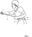
- the end of the rope on the handle 13 is manually pulled out of the handpiece 1 and fastened by means of the coupling element 13 on a belt 14 at the waist of the user (see. Fig. 2 ).
- Fig. 2 shows an example of such arranged on the body of the user belt 14, which has only one attachment position 18 for the coupling element 12 and the handle 13 in this case.
- the attachment position 18 on the belt 14 determines the direction of the drawn-out rope 11 from the handle 1 to the body. This direction is defined by means of a coupling element which is formed corresponding to the coupling element 12 on the handle 13 and receives this.
- the Connection of both coupling elements together is designed for example as a bayonet lock.
- embodiments of the belt 14 may be provided with a plurality of such mounting positions 18, so that with the choice of different mounting positions 18, the cable extension direction can be varied.
- the concept of the invention is the training and use of a wear on the upper body belt system instead of in Fig. 2 illustrated hip belt to increase the range of variation in selectable directions of extension.
- the number and arrangement of the attachment positions 18 are preferably carried out symmetrically to the body center and thereby assigned to the left hand and the right hand.
- the handle 1 is designed so that the cable drum 5 including its axis 15 is within the hand, which encloses the handle 1, which advantageously has the consequence that the rope 11 below the hand, namely directly on the hand edge, from the Handle 1 exits and runs in the direction of the body of the user.
- FIG. 4a is already based Fig. 1 and Fig. 3 explained handle 1 shown again, and although uncut with a view towards the outer surface 8 (see. Fig. 1 ), here the handle 1 for the left hand.
- Fig. 4b shows the same handle 1 in a section through the in Fig. 4a specified level BB.
- Illustrated here are exemplary embodiments of the cable drum 5 and a spring housing 20 in which a mechanically connected to the cable drum 5 coil spring is housed, which provides the pull-out force, which is applied manually to unwind the cable end of the cable drum 5.
- the spiral spring generates the rewinding force, which rewinds the cable 11 onto the cable drum 5 as soon as the pull-out force decreases or becomes smaller than the restoring force. This is done in response to the arm movements which increase or decrease the distance between the handle 1 and the attachment positions 18 on the user's body.
- the thereby executed by the cable drum 5 rotational movements "R" are in the FIGS. 1a and 3 shown.
- Fig. 5 shows a perspective view of a handle 1, which is provided on its underside with a label "L", which assigns the handle 1 of the left hand.
- L which assigns the handle 1 of the left hand.
- This marking is particularly helpful for the embodiments in which the two belonging to the trimming device handles 1 in details mirror images differ and thus the left or right hand are assigned.
- the exit direction of the cable 11 is inclined out of the handle 1 to the body of the user, which reversed applies also to the handle 1, which is provided for the right hand.
- a handle 1 of the trimming device according to the invention is shown according to a second embodiment in a lateral interior view.
- Fig. 6b shows the top view of the same handle 1 in a section through the in Fig. 6b specified level CC.
- the handle 1 consists of an upper housing part 2 and a lower housing part 3. Both housing parts 2, 3 enclose a cavity 4, in which a cable drum 5 is arranged.
- the outer contour of the handle 1 is ergonomically adapted to a gripping hand, wherein the outer surface 6 of the palm lies against the outer surfaces 7 and 8 are enclosed with four fingers of the hand and the thumb on the outer surface 9 or laterally on the outer surface 10 (FIG. see. Fig. 6b ) can rest.
- the cable drum 5 is thereby including its drum axis 15 within the handle 1 enclosing the palm.
- a cable 11 is wound under spring tension, one end of which is attached to the circumference of the cable drum 5, while the other end is led out through an introduced into the housing part 2 cable outlet opening 22 from the handle 1 (see. Fig. 6b ).
- the lead out end of the rope is as out Figure 6b If the trimmer is to be used, the end of the rope is pulled out manually by means of the grip 13 from the handpiece 1 and by a coupling element 12 (see. Fig. 8a ) is fastened to a position resting relative to the handpiece 1, which position is for example at the hip of the user.
- Fig. 6b exemplary embodiments of the cable drum 5 and a spring housing 20 can be seen.
- the spring housing 20 is a mechanically connected to the cable drum 5 coil spring is housed, which provides the pull-out force, which is applied manually to unwind the cable end of the cable drum 5.
- the spiral spring generates the rewinding force, which rewinds the cable 11 onto the cable drum 5 as soon as the pull-out force decreases or becomes smaller than the restoring force. This happens in response to the arm movements, which increase or decrease the distance between the handle 1 and the position at which the handle 13 is attached.
- the in Fig. 7 belt 14 shown by way of example and arranged on the hip of the user has such a fastening position 18 for the grip 13.
- the attachment of the handle 13 to the belt 14 can be done for example by means of a known bayonet closure, wherein the coupling element 12 forms an element of the bayonet closure.
- the attachment position 18 on the belt 14 determines the direction of the drawn-out rope 11 from the handle 1 to the user's body.
- the invention provides that the rope 11 centrally "M" in height of the handball of the hand exits the handle 1, which surrounds the handle 1, wherein the distance a between the exit position of the cable 11 from the Handle 1 on the one hand and the pivot point 23 within the wrist area 17 on the other hand (see. Fig. 6a ) is reduced to a minimum level and thereby also the force exerted by the pull-out force on the wrist leverage is reduced to a minimum.
- the cable outlet opening 22 on the handle 1 is not in rectilinear Extension of the direction is arranged, in which the cable 11 is unwound against bias of the cable drum 5 or wound up as a result of a restoring force on the cable drum 5, but is laterally offset to it, as in Figure 6b can be seen.
- this lateral offset at the same time the possibility of contact between the rope 11 and the palm is reduced during use.
- the lateral offset is achieved by deflecting or changing the cable guide direction.
- Fig. 6b shows, the deflection by means of roller 24 or by means of slider 25 is made, both variants are shown here with respect to their positioning here only by way of example.
- the deflection is exclusively by means of rollers 24 or the deflection exclusively by means of sliders 25 as well within the scope of the invention as their example in Fig. 6b shown combined application.
- the slightly increased friction in the choice of sliders 25 in comparison to the deflection by means of rollers 24 is not disadvantageous because the trimming device is intended in any case intended for manual overcoming the pull-out force.
- the term slider 25 in the context of the invention is to be understood as meaning both a curved portion of the inner wall of the housing part 2 for this purpose, and a component with a curved contour which is manufactured separately and placed on the inner wall.
- the direction of the lateral offset relative to the rectilinear extension of the unwinding and winding direction of the cable 11 from or to the cable drum 5 is defined as being in Fig. 6a perpendicular to the drawing plane and in Fig. 6b lies in the drawing plane.
- Fig. 8 shows the already based Fig. 6 explained handle 1 in exterior views, wherein Fig. 8a represents the handle 1 with a view of the outer surface 8, while Fig. 8b the side view, namely the view of the outer surface 6 shows. How out Fig. 8a and Fig. 8b can be seen, on the outer surfaces 6 and 7 strip-shaped knobs 16 are provided, which give the enclosing hand additional support.
- the cable 11 is passed for the purpose of lateral offset by a protuberance 26, which is worked on the outer surface 8. It is expressly on it that the representation is not to scale, that is, both the amount of lateral offset and the dimension of the protuberance 26 are appropriate to the physical conditions of the user, such as children or adult male or female persons.
- embodiments of the belt 14 may be provided with a plurality of fastening positions 18, so that with the choice of different mounting positions 18, the cable extension direction is variable.
- the concept of the invention is the training and use of a wear on the upper body belt system instead of in Fig. 7 shown hip belt to increase the range of different selectable cable pullout directions.
- the number and arrangement of the attachment positions 18 are preferably carried out symmetrically to the center of the body and thereby assigned to the left hand or the right hand or body side.
- Fig. 9 shows a self-explanatory plan view of both handles of the trimming device according to the invention with markings 21 for the purpose of defined assignment to the left and right hand or body side of a user.
- FIGS. 10 to 12 are shown schematically are not part of the invention.
- the left hand grip 1 and the right hand grip 1 are each arranged on a glove 27, preferably integrated into the glove 27.
- This further embodiment is in FIG. 10 shown schematically, here by way of example a left glove.
- the handle, the left-hand grip and the right-hand grip, respectively are combined with a sports pole.
- the sports floor can be a Nordic Walking floor, a fitness floor, an inline skating floor, a ski pole or another floor designed for sports purposes. Schematically, such an embodiment and use in the FIGS. 11 to 13 shown.
- FIG. 11 In the embodiment and use variant according to the FIG. 11 is at a sports floor 28 in the head-side end portion 31 of its handle 29 a handle arranged, wherein in a preferred embodiment, the handle is integrated into this end portion 31 and is adjusted accordingly by its dimensions.
- the rope is not led out of the handle below the edge of the hand but directly above the hand of the user, who grasps the holding section 30.
- the rope within the handle 29, in particular of the holding portion 30 is guided to the lower end portion of the handle 29 and deflected there, so that the rope 11 is also led out here below the hand edge of the user.
- the respective handle according to the invention is not arranged on or in the handle 29 of the sports stock 28, but provided directly below the handle 29 on the shaft 33 of the sports stock 28.
- the handle according to the invention is arranged in a special housing 32, which at the same time has a fastening unit with which this special handle with its housing 32 on the shaft 33 can be fixed.
- the attachment unit is such that the special Handle is optionally solvable.
- the rope 11 is led out in the upper region of the housing 32, so that it also moves immediately below the user's hand edge, so that the distance a to the pivot point 23 is minimal.
Landscapes
- Health & Medical Sciences (AREA)
- Orthopedic Medicine & Surgery (AREA)
- General Health & Medical Sciences (AREA)
- Physical Education & Sports Medicine (AREA)
- Life Sciences & Earth Sciences (AREA)
- Biophysics (AREA)
- Engineering & Computer Science (AREA)
- Human Computer Interaction (AREA)
- Rehabilitation Tools (AREA)
Description
Die Erfindung bezieht sich auf ein Trimmgerät, das zur Unterstützung des Aufbaus der Muskulatur des menschlichen Körpers, insbesondere der Muskulatur beider Schulterbereiche und der Bereiche beider Arme - einschließlich der Hände - ausgebildet ist.The invention relates to a trimming device, which is designed to support the structure of the musculature of the human body, in particular the musculature of both shoulder areas and the areas of both arms - including the hands.
Trimmgeräte zum Trainieren der Muskulatur des menschlichen Körpers sind in verschiedenen Ausführungen bekannt und gebräuchlich, darunter Trimmgeräte, die während des Joggens oder Gehens oder auch im Sitzen oder Stehen von Personen genutzt werden können, um die Muskulatur des Oberkörpers, insbesondere des Schulterbereichs einschließlich der Arme, zu trainieren.Trimming machines for exercising the musculature of the human body are known and used in various designs, including trim devices that can be used while jogging or walking or even while sitting or standing by persons, around the muscles of the upper body, in particular the shoulder area including the arms. to train.
Ein diesbezüglich aus der
Ein weiteres Trimmgerät ist in der
Nachteilig bei dem letztgenannten Gerät ist, dass die dehnbaren Seile naturgemäß einem Verschleiß unterliegen, der abnehmende, also nicht gleichbleibende Dehnungskräfte zur Folge hat. Außerdem weisen die Seile eine bestimmte Länge auf und sind für bestimmte Zugkräfte ausgelegt, wodurch sie nur für Nutzer geeignet sind, die eine dazu passende Armlänge oder einen den Zugkräften entsprechenden Trainingszustand haben. Ein solches Trimmgerät ist für mehrere Nutzer mit unterschiedlichem Trainingszustand und unterschiedlicher Kondition nur eingeschränkt nutzbar.A disadvantage of the latter device is that the stretchy ropes are naturally subject to wear, which has decreasing, ie non-uniform expansion forces result. In addition, the ropes have a certain length and are designed for certain tensile forces, making them suitable only for users who have a matching arm length or a training condition corresponding to the tensile forces. Such a trimming device can only be used to a limited extent for several users with different training conditions and different stamina.
Ein Trimmgerät anderer Konstruktion ist aus der
Auch bei diesem Gerät werden in Abhängigkeit von wechselseitigen Hand- bzw. Armbewegungen, die den Abstand zwischen dem Hüftgürtel und den Handgriffen vergrößern, Seile unter Kraftaufwand von Seiltrommeln abgewickelt. Damit bei diesem Abwickeln die Muskeln trainierende Zugkräfte wirken, sind in beiden Seiltrommeln Reibscheiben vorgesehen, die den Seilauszug erschweren. Die Reibung ist einstellbar, so dass die zu überwindenden Zugkräfte abhängig von der jeweils eingestellten Reibung variabel sind. Zugleich werden beim Ausziehen der Seile Rückstellkräfte erzeugt, die jeweils für die Wiederaufwicklung auf die Seiltrommeln sorgen, sobald der Abstand zwischen dem Hüftgürtel und dem betreffenden Handgriff verringert wird. Das Aufwickeln wird durch die Reibscheiben nicht gebremst.Also in this device, depending on mutual hand or arm movements that increase the distance between the girdle and the handles, ropes unwound under the power of cable drums. In order for the muscles to exert tensile forces during unwinding, friction disks are provided in both cable drums, which complicate the cable extension. The friction is adjustable, so that too overcoming tensile forces are variable depending on the respective set friction. At the same time restoring forces are generated when removing the ropes, which provide each for the rewinding on the cable drums, as soon as the distance between the girdle and the handle in question is reduced. The winding is not slowed down by the friction discs.
Ein weiteres Trimmgerät ist aus der
Bei beiden letztgenannten Trimmgeräten sind zur Erzeugung und Einstellung der Seilauszugskräfte einerseits und zur Erzeugung der Rückstellkräfte andererseits gesonderte Vorrichtungen vorhanden, was aufgrund des verhältnismäßig großen räumlich Aufbaues und Gewichtes im Hinblick auf die Handhabung durch den Nutzer nachteilig ist.In both latter trim devices for generating and adjusting the pull-rope forces on the one hand and for generating the Restoring forces on the other hand separate devices present, which is disadvantageous due to the relatively large space structure and weight in terms of handling by the user.
In
Allerdings wirkt hier beim Ausziehen des Seiles aus dem Handgriff eine nicht unwesentliche Komponente der Federkraft insofern ergonomisch ungünstige auf die Hand des Nutzers, als dieser Kraftkomponente entgegenwirkt werden muss, um eine Verdrehung der Hand um das Handgelenk zu vermeiden. Der Nachteil besteht demzufolge nicht nur darin, dass das Handgelenk in unerwünschter Weise belastet wird, sondern auch die Ausnutzung der Federkraft zum eigentlichen Zweck, nämlich dem Muskulaturaufbau, nur begrenzt erfolgt.However, here when pulling the rope out of the handle a not insignificant component of the spring force insofar ergonomically unfavorable on the user's hand, as this force component must be counteracted to avoid twisting the hand around the wrist. The disadvantage is therefore not only that the wrist is loaded in an undesirable manner, but also the utilization of the spring force to the actual purpose, namely the muscular structure, only limited.
Ausgehend von diesem Stand der Technik liegt der Erfindung die Aufgabe zugrunde, ein Trimmgerät anzugeben, welches sowohl von Personen unterschiedlicher Konstitution und unterschiedlicher Kondition nutzbar ist als auch die Nachteile des Standes der Technik bezüglich der Handhabung durch den Nutzer nicht mehr aufweist. Nebenbei soll bei diesem Trimmgerät die auf das Handgelenk ausgeübte Hebelwirkung noch weiter verringert sein.Based on this prior art, the present invention seeks to provide a trimming device, which is used by both persons of different constitution and different condition as well as the disadvantages of the prior art in terms of handling by the user no longer has. Incidentally, in this trimming device, the leverage applied to the wrist should be further reduced.
Erfindungsgemäß ist ein Trimmgerät der eingangs genannten Art ausgestattet mit zwei Handgriffen, von denen einer zum Umgreifen mit der rechten Hand, der andere zum Umgreifen mit der linken Hand ausgebildet ist. Dabei weist jeder Handgriff eine Seiltrommel auf, deren Trommelachse sich - bei Benutzung des Trimmgerätes - sowohl innerhalb der umgreifenden Hand befindet als auch im Wesentlichen senkrecht zur Handinnenfläche ausgerichtet ist.According to a trimming device of the type mentioned above is equipped with two handles, one of which is designed to grip around with the right hand, the other for gripping with his left hand. In this case, each handle on a cable drum, the drum axis is - when using the trimming device - both within the encompassing hand and is aligned substantially perpendicular to the palm of the hand.
Weiterhin ist auf jeder Seiltrommel ein Seil unter Vorspannung aufgewickelt, von dem ein Seilende aus dem Handgriff herausgeführt und - bei Benutzung des Trimmgerätes - mit einer vorgegebenen Position am Körper eines Nutzers, vorzugsweise am Rumpf, mechanisch fest verbunden ist. Armbewegungen, welche die Abstände zwischen den Handgriffen und den Befestigungspositionen am Körper vergrößern, wickeln die Seile durch Überwindung der Vorspannung ab, die dabei erforderliche manuelle Kraftausübung unterstützt den Muskulaturaufbau.Furthermore, a cable is wound under pretension on each cable drum, led out of which a rope end of the handle and - when using the trimming device - with a predetermined position on the body of a user, preferably on Hull, mechanically firmly connected. Arm movements, which increase the distances between the handles and the attachment positions on the body, unwind the ropes by overcoming the bias, thereby requiring manual exercise supports the muscle structure.
Dieses Training kann ausgeführt werden, wenn sich die nutzende Person in Ruhe relativ zu ihrer Umgebung befindet, beispielsweise stehend, aber auch in Bewegung, wie beim Joggen. Die Nutzung kann zum sportlichen Training, jedoch auch im Zusammenhang mit Rehabilitations- und physiotherapeutischen Maßnahmen erfolgen.This training can be performed when the occupant is at rest relative to their environment, for example, standing, but also on the move, such as jogging. The use can be done for sports training, but also in connection with rehabilitation and physiotherapy.
Das erfindungsgemäße Trimmgerät zeichnet sich unter anderem dadurch aus, dass sich die Achse der jeweiligen Seiltrommel innerhalb der umgreifenden Hand befindet, wobei sie jeweils senkrecht zur Handinnenfläche ausgerichtet sind, und die Austrittsöffnung für das Seil bei beiden Handgriffen unmittelbar seitlich neben oder unmittelbar unterhalb einer für die Anlage des Handballens vorgesehenen Außenfläche des Handgriffs angeordnet ist. Dies bietet einen im Vergleich zum Stand der Technik wesentlichen ergonomischen Vorteil, da der Abstand zwischen der Austrittsposition des Seiles aus dem jeweiligen Handgriff und dem Handgelenk auf ein Mindestmaß reduziert ist und damit auch die von der Auszugskraft auf das Handgelenk ausgeübte nachteilige Hebelwirkung auf ein Minimum verringert ist.The trim device according to the invention is characterized inter alia by the fact that the axis of the respective cable drum is located within the encompassing hand, wherein they are each aligned perpendicular to the palm, and the outlet for the rope in both handles immediately laterally next to or immediately below one for the Plant of the handball provided outer surface of the handle is arranged. This provides a significant ergonomic advantage over the prior art since the distance between the exit position of the rope from the respective handle and wrist is minimized and thus minimizes the adverse leverage exerted on the wrist by the withdrawal force is.
In einer ersten bevorzugten Ausführungsform der Erfindung ist die Erzeugung der Vorspannung, unter der die Seile auf den Seiltrommeln aufgewickelt sind, mittels Spiralfedern vorgesehen, die ebenfalls innerhalb der Handgriffe angeordnet sind. Die Spiralfedern erzeugen beim Abwickeln der Seile Rückstellkräfte, die einerseits den manuell zu überwindenden Auszugskräften entsprechen, andererseits dazu führen, dass bei Verringerung des Abstandes zwischen dem jeweiligen Handgriff und der Befestigungsposition des Seiles am Körper das Seil wieder auf die Seiltrommel aufgewickelt wird. Die Spiralfedern sind den Seiltrommeln funktionell so zugeordnet, dass ihre Federkraft dem Abwickeln des Seiles von der Seiltrommel entgegenwirkt.In a first preferred embodiment of the invention, the generation of the bias under which the ropes are wound on the cable drums is provided by means of spiral springs, which are also arranged inside the handles. The coil springs produce when unwinding the ropes restoring forces, on the one hand correspond to the manually to be overcome pull-out forces, on the other hand cause the rope is rewound on the cable drum when reducing the distance between the respective handle and the attachment position of the rope on the body. The coil springs are functionally assigned to the cable drums so that their spring force counteracts the unwinding of the rope from the cable drum.
In einer weiteren bevorzugten Ausführungsform des erfindungsgemäßen Trimmgerätes sind Mittel zur Variation der Vorspannung vorgesehen, unter der die Seile auf den Seiltrommeln aufgewickelt sind. Diese sind beispielsweise ausgeführt als Wechseleinrichtungen zum Austausch von Spiralfedern mit unterschiedlichen Federkonstanten gegeneinander. Alternativ oder auch zusätzlich dazu können Stelleinrichtungen vorhanden sein, die zum Erhöhen oder Verringern der Vorspannung ausgebildet sind. Dies kann in an sich bekannter Weise mit Verstellrädern an den Handgriffen erfolgen, mit dem die Vorspannung der Spiralfeder entweder stufenlos oder progressiv veränderbar ist.In a further preferred embodiment of the trimming device according to the invention means for varying the bias are provided under which the ropes are wound on the cable drums. These are, for example, designed as changing devices for the exchange of coil springs with different spring constants against each other. Alternatively or in addition thereto, adjusting devices may be provided which are designed to increase or decrease the preload. This can be done in a conventional manner with adjusting wheels on the handles, with which the bias of the coil spring is either continuously or progressively variable.
Bei geeigneter Wahl der Spiralfedern kann die Federkraft derart vorgegeben werden, dass sie konstant ist. Das bedeutet, dass die Kraft, mit der das Seil von der Seiltrommel abgewickelt wird, von der abgewickelten Seillänge unabhängig ist. Alternativ kann die Federkraft jedoch auch linear zunehmend sein, so dass, je länger das abgewickelte Seil wird, die Federkraft und dementsprechend die zum Abwickeln nötige Auszugskraft umso stärker zunimmt.With a suitable choice of the coil springs, the spring force can be specified such that it is constant. This means that the force with which the rope is unwound from the rope drum is independent of the unwound rope length. Alternatively, however, the spring force can also be linearly increasing, so that the longer the unwound rope, the spring force and, accordingly, the extraction force necessary for unwinding increases all the more.
Um eine konstante Federkraft zu erreichen, ist das Seil auf eine konische Trommel aufgewickelt. Diese Seiltrommel hat vorzugsweise Seilrillen.To achieve a constant spring force, the rope is wound on a conical drum. This cable drum preferably has rope grooves.
Die äußeren Formen der beiden Handgriffe sind insofern ungleich ausgeführt, als ein Handgriff ergonomisch der linken Hand, der andere Handgriff ergonomisch der rechten Hand angepasst ist. Die diesbezüglichen Merkmale, durch die sich beide Handgriffe unterscheiden, sind spiegelbildlich ausgeführt. So sind beispielsweise
die Austrittsöffnungen für die Seile an den Handgriffen so gestaltet, dass die Seilaustrittsrichtung jeweils zum Körper hin geneigt ist.The outer shapes of the two handles are designed unequal in that one handgrip is ergonomically adapted to the left hand, the other handgrip is ergonomically adapted to the right hand. The relevant features by which both handles differ are mirror images. Such are, for example
the outlet openings for the ropes on the handles designed so that the rope exit direction is inclined in each case to the body.
In einer besonders bevorzugten Ausführungsform sind für die aus den Handgriffen herausgeführten Seilenden mehrere verschiedene Befestigungspositionen am Rumpf des Körpers vorhanden und zur Auswahl vorgesehen. Dies ermöglicht es, die Auszugsrichtungen der Seile aus den Handgriffen zusätzlich zu variieren. Definiert sind die Befestigungspositionen beispielsweise mittels eines am Rumpf, vorzugsweise an der Hüfte, anzubringenden Gurtes oder eines um den Oberkörper zu legenden Gurtsystems. Gurt oder Gurtsystem weisen an den Befestigungspositionen Koppelelemente für die Seilenden auf, während an den Seilenden dazu korrespondierende Koppelelemente vorhanden sind, die eine leicht herzustellende und auch wieder zu lösende Verbindung ermöglichen und beispielsweise in Form eines Bajonettverschlusses oder einer Haken-Öse-Verbindung ausgebildet sein können.In a particularly preferred embodiment, a plurality of different attachment positions on the trunk of the body are provided for the outgoing from the handles cable ends and provided for selection. This makes it possible to additionally vary the extension directions of the ropes from the handles. Are defined the attachment positions, for example, by means of a belt to be attached to the torso, preferably at the hip, or a belt system to be placed around the upper body. Belt or belt system have at the attachment positions coupling elements for the cable ends, while at the cable ends to corresponding coupling elements are provided, which allow easy to manufacture and also to be loosened connection and may be formed, for example in the form of a bayonet lock or a hook-eye connection ,
Optional ist die Kopplung des erfindungsgemäßen Trimmgerätes mit Mitteln zum Messen von Kennwerten vorgesehen, die den Trainingszustand des Körpers bzw. der Muskulatur charakterisieren, wie beispielsweise Seilauszugskraft- und Trainingszeitmessung und deren Verknüpfung zur Ermittlung des Energieverbrauchs, Pulsfrequenzmessung und/oder Messung der Körpertemperatur. So kann eine Überwachung und Optimierung des Trainings vorgenommen werden. In diesem Zusammenhang können auch Einrichtungen zur visuell wahrnehmbaren Anzeige und/oder zur Speicherung der ermittelten Ergebnisse vorhanden sein.Optionally, the coupling of the trimming device according to the invention is provided with means for measuring characteristics that characterize the training state of the body or the musculature, such as Seilauszugskraft- and training time measurement and their link to determine the energy consumption, pulse rate measurement and / or measurement of body temperature. Thus, a monitoring and optimization of training can be made. In this context, devices for the visually perceptible display and / or for storing the determined results may also be present.
In einer weiteren vorteilhaften Ausführungsform sind die Handgriffe des erfindungsgemäßen Trimmgerätes mit Bügeln zum Schutz der Handrücken gegen Stoßverletzungen versehen. Optional kann weiterhin mindestens einer der Handgriffe mit einer Lichtquelle ausgestattet sein, die vorzugsweise bei Dunkelheit zur Aussendung eines Lichtsignals und somit im Freien zur Verhinderung von Zusammenstößen mit entgegenkommenden Personen dient.In a further advantageous embodiment, the handles of the trimming device according to the invention are provided with brackets to protect the back of the hand against impact injuries. Optionally, at least one of the handles with a light source can continue be equipped, preferably in the dark to emit a light signal and thus in the open to prevent collisions with oncoming persons.
In einer weiteren vorteilhaften Ausführungsform ist erfindungsgemäß bei einem Trimmgerät der genannten Art der Abstand zwischen der Austrittsposition des Seiles aus dem Handgriff einerseits und dem Drehpunkt innerhalb des Handgelenkbereiches andererseits dadurch weiter reduziert, dass sich die Seilaustrittsöffnung nicht mehr unterhalb der Handkante befindet und auch nicht in geradliniger Verlängerung der Richtung angeordnet ist, in der das Seil von der Seiltrommel abgewickelt bzw. infolge einer Rückstellkraft wieder auf die Seiltrommel aufgewickelt wird, sondern die Seilaustrittsöffnung zu dieser Richtung seitlich versetzt positioniert ist.In a further advantageous embodiment, the distance between the exit position of the rope from the handle on the one hand and the pivot point within the wrist area on the other hand, according to the invention further reduced in a trimming device of the type mentioned that the cable outlet opening is no longer below the edge of the hand and not in rectilinear Extension of the direction is arranged, in which the cable is unwound from the cable drum or wound up as a result of a restoring force on the cable drum, but the cable outlet opening is positioned laterally offset to this direction.
Der Abstand zwischen der Austrittsposition des Seiles aus dem Handgriff und dem Handgelenkbereich konnte so nochmals reduziert und dadurch auch die von der Auszugskraft nachteiliger weise auf das Handgelenk ausgeübte Hebelwirkung weiter verringert werden.The distance between the exit position of the rope from the handle and the wrist area could be further reduced and thus the disadvantage of the pull-out force on the wrist leverage effect can be further reduced.
Der seitliche Versatz wird durch Umlenkung der Seilführungsrichtung mittels Rollen oder Gleitstücken erzielt.The lateral offset is achieved by deflection of the cable guide direction by means of rollers or sliders.
Die Erfindung wird nachfolgend nicht einschränkend anhand von Ausführungsbeispielen näher erläutert. In den zugehörigen Zeichnungen zeigen:
- Fig. 1
- einen der Handgriffe des erfindungsgemäßen Trimmgerätes in einer Schnittdarstellung mit einer seitlichen Innenansicht (
Fig. 1a ) und in einer ungeschnittenen Frontansicht (Fig. 1b ); - Fig. 2
- einen Nutzer während des Trainings mit dem erfindungsgemäßen Trimmgerät;
- Fig. 3
- die Schnittdarstellung des Handgriffs aus
Fig. 1a mit teilweise ausgezogenem Seil und dem Bereich, in dem sich das Handgelenk des Nutzers befindet; - Fig. 4
- nochmals den Handgriff aus
Fig. 1 , jedoch ungeschnitten und mit Blickrichtung auf die Gegenseite (Fig. 4a ), und den Handgriff in einem Schnitt durch die inFig. 4a angegebene Ebene BB (Fig. 4b ); - Fig. 5
- einen für die linke Hand ausgebildeten Handgriff in Perspektivdarstellung;
- Fig. 6
- einen Handgriff des erfindungsgemäßen Trimmgerätes in einer zweiten Ausführung, ausgeführt für das Umgreifen mit der rechten Hand, in einer seitlichen Innenansicht (
Fig. 6a ) und einer Draufsicht in Schnittdarstellung (Fig. 6b ); - Fig. 7
- eine Art der Benutzung des erfindungsgemäßen Trimmgerätes, wobei ein aus dem Handgriff nach
Fig. 6 unter Vorspannung herausgezogenes Seilende mit einem Gurt verbunden ist, den der Benutzer um die Hüfte trägt; - Fig. 8
- wiederum den Handgriff aus
Fig. 6 , hier jedoch in Außenansichten; - Fig. 9
- eine Draufsicht auf beide Handgriffe des erfindungsgemäßen Trimmgerätes mit Zuordnung zur linken und rechten Hand bzw. Körperseite eines Benutzers;
- Fig. 10
- eine Ausführung eines Trimmgerätes, hier der linke Handgriff;
- Fig. 11
- eine Ausführung eines Trimmgerätes, in spezieller Verwendung mit einem Sportstock;
- Fig. 12
- eine Variante der Ausführung des Trimmgerätes nach
Fig. 11 und - Fig. 13
- eine weitere Variante der Ausführung des Trimmgerätes nach
Fig. 11 .
- Fig. 1
- one of the handles of the trimming device according to the invention in a sectional view with a lateral interior view (
Fig. 1a ) and in an uncut front view (Fig. 1b ); - Fig. 2
- a user during exercise with the trim device according to the invention;
- Fig. 3
- the sectional view of the handle
Fig. 1a with partially pulled-out rope and the area in which the user's wrist is located; - Fig. 4
- again the handle
Fig. 1 , but uncut and looking towards the other side (Fig. 4a ), and the handle in a section through the inFig. 4a specified level BB (Fig. 4b ); - Fig. 5
- a trained for the left hand handle in perspective view;
- Fig. 6
- a handle of the trimming device according to the invention in a second embodiment, designed for grasping with the right hand, in a lateral interior view (
Fig. 6a ) and a top view in sectional view (Fig. 6b ); - Fig. 7
- a kind of use of the trimming device according to the invention, wherein a from the handle after
Fig. 6 tensioned under cable tension is connected to a strap which the user wears around the waist; - Fig. 8
- turn the handle off
Fig. 6 , but here in external views; - Fig. 9
- a plan view of both handles of the trimming device according to the invention with assignment to the left and right hand or body side of a user;
- Fig. 10
- an embodiment of a trimming device, here the left handle;
- Fig. 11
- an embodiment of a trimmer, in particular use with a sports stick;
- Fig. 12
- a variant of the execution of the trimmer after
Fig. 11 and - Fig. 13
- another variant of the execution of the trimmer after
Fig. 11 ,
Die in den Figuren angezogenen Bezugsziffern haben jeweils die gleiche Bedeutung, auch wenn sie in der Beschreibung der Ausführungen nicht zu jeder Figur ausdrücklich genannt werden.The reference numerals drawn in the figures have the same meaning each, even if they are not explicitly mentioned in the description of the embodiments for each figure.
In
Wie aus
In
Auf die Seiltrommel 5 ist unter Federvorspannung ein Seil 11 aufgewickelt, das an einem Ende, an dem sich ein mit einem Koppelelement 12 versehenes Griffstück 13 befindet, durch eine Öffnung im oberen Gehäuseteil 2 hindurch aus dem Handgriff 1 herausgeführt ist. Zur Vorbereitung der Benutzung des Trimmgerätes wird das Seilende am Griffstück 13 manuell aus dem Handstück 1 herausgezogen und mittels des Koppelelementes 13 an einem Gurt 14 an der Hüfte des Benutzers befestigt (vgl.
In weiterführenden, ebenfalls im Rahmen der Erfindung liegenden Ausgestaltungen kann der Gurt 14 mit mehreren derartigen Befestigungspositionen 18 versehen sein, so dass mit der Wahl unterschiedlicher Befestigungspositionen 18 die Seilauszugsrichtung variiert werden kann. In den Erfindungsgedanken einbezogen ist die Ausbildung und Verwendung eines am Oberkörper zu tragenden Gurtsystems anstelle des in
Der Handgriff 1 ist erfindungsgemäß so ausgeführt, dass sich die Seiltrommel 5 einschließlich ihrer Achse 15 innerhalb der Hand befindet, die den Handgriff 1 umschließt, was vorteilhaft zur Folge hat, dass das Seil 11 unterhalb der Hand, nämlich unmittelbar an der Handkante, aus dem Handgriff 1 austritt und in Richtung zum Körper des Nutzers verläuft.The
Mit dieser wesentlich vom Stand der Technik abweichenden technischen Lösung ist es gelungen, den Abstand a zwischen der Austrittsposition des Seiles 11 aus dem Handgriff 1 und dem Handgelenkbereich auf ein Mindestmaß zu reduzieren und damit die von den Auszugskräften auf das Handgelenk ausgeübte Hebelwirkung zu minimieren, wie es aus der
In
In
Wie aus
Auf die Seiltrommel 5 ist unter Federvorspannung ein Seil 11 aufgewickelt, von dem ein Ende am Umfang der Seiltrommel 5 befestigt ist, während das andere Ende durch eine in das Gehäuseteil 2 eingebrachte Seilaustrittsöffnung 22 hindurch aus dem Handgriff 1 herausgeführt ist (vgl.
Aus
Der in
Die Befestigungsposition 18 am Gurt 14 bestimmt die Richtung des ausgezogenen Seiles 11 vom Handgriff 1 zum Körper des Benutzers hin. Um diese Richtung ergonomisch optimal zu gestalten, ist erfindungsgemäß vorgesehen, dass das Seil 11 mittig "M" in Höhe des Handballens der Hand aus dem Handgriff 1 austritt, die den Handgriff 1 umschließt, wobei der Abstand a zwischen der Austrittsposition des Seiles 11 aus dem Handgriff 1 einerseits und dem Drehpunkt 23 innerhalb des Handgelenkbereichs 17 andererseits (vgl.
Weiterhin ist hier auch erfindungswesentlich, dass die Seilaustrittsöffnung 22 am Handgriff 1 nicht in geradliniger Verlängerung der Richtung angeordnet ist, in der das Seil 11 gegen Vorspannung von der Seiltrommel 5 abgewickelt bzw. infolge einer Rückstellkraft wieder auf die Seiltrommel 5 aufgewickelt wird, sondern sich seitlich dazu versetzt befindet, wie in
Der seitliche Versatz wird durch Umlenkung bzw. Änderung der Seilführungsrichtung erzielt. Wie aus
Die Richtung des seitlichen Versatzes relativ zur geradlinigen Verlängerung der Ab- und Aufwickelrichtung des Seiles 11 von bzw. auf die Seiltrommel 5 ist insofern definiert, als sie in
Im Vergleich zu bisher bekannten Trimmgeräten dieser Art ist es mit der Erfindung gelungen, den Abstand a zwischen der Austrittsposition des Seiles 11 aus dem Handgriff 1 und dem Drehpunkt 23 des Handgelenks auf ein Mindestmaß zu reduzieren und damit die von der Auszugskraft auf das Handgelenk ausgeübte Hebelwirkung zu minimieren.Compared to previously known trim devices of this type, it has been possible with the invention to reduce the distance a between the exit position of the
Wie aus der Zusammenschau von
In weiterführenden, ebenfalls im Rahmen der Erfindung liegenden Ausgestaltungen kann der Gurt 14 mit mehreren Befestigungspositionen 18 versehen sein, so dass mit der Wahl unterschiedlicher Befestigungspositionen 18 die Seilauszugsrichtung variierbar ist. In den Erfindungsgedanken einbezogen ist die Ausbildung und Verwendung eines am Oberkörper zu tragenden Gurtsystems anstelle des in
Alle in der vorstehenden Beschreibung erwähnten sowie auch die allein aus den Zeichnungen entnehmbaren Merkmale sind weitere Bestandteile der Erfindung auch wenn sie nicht besonders hervorgehoben und/oder in den Ansprüchen erwähnt sind.All mentioned in the foregoing description as well as the removable only from the drawings features are further components of the invention, even if they are not particularly highlighted and / or mentioned in the claims.
Die folgenden Ausführungsbeispiele, die in
In einer anderen, weiteren bevorzugten Ausführungsform eines Trimmgerätes ist der Handgriff, der linke Handgriff bzw. der rechte Handgriff, jeweils mit einem Sportstock kombiniert. Der Sportstock kann hierbei zum Beispiel ein Nordic-Walking-Stock, ein Fitness-Stock, ein Inline-Skating-Stock, ein Skistock oder ein anderer zu Sportzwecken ausgebildeter Stock sein. Schematisch ist eine solche Ausführungsform und Verwendung in den
Bei der Ausführungs- und Verwendungs-Variante gemäß der
Bei dieser Variante und ihrer Verwendung wird das Seil nicht unterhalb der Handkante sondern unmittelbar oberhalb der Hand des Benutzers, welcher den Halteabschnitt 30 umgreift, aus dem Handgriff herausgeführt.In this variant and its use, the rope is not led out of the handle below the edge of the hand but directly above the hand of the user, who grasps the holding
Bei einer weiteren Ausführungsvariante nach
- 11
- Handgriffhandle
- 22
- Gehäuseteilhousing part
- 33
- Gehäuseteilhousing part
- 44
- Hohlraumcavity
- 55
- Seiltrommelcable drum
- 66
- Außenflächeouter surface
- 77
- Außenflächeouter surface
- 88th
- Außenflächeouter surface
- 99
- Außenflächeouter surface
- 1010
- Außenflächeouter surface
- 1111
- Seilrope
- 1212
- Koppelelementcoupling element
- 1313
- Griffstückgrip
- 1414
- Gurtbelt
- 1515
- Trommelachsedrum axis
- 1616
- Noppenburl
- 1717
- Handgelenkbereichwrist
- 1818
- Befestigungspositionmounting position
- 1919
- SeilaustrittsöffnungCable outlet opening
- 2020
- Federgehäusespring housing
- 2121
- KennzeichnungLabelling
- 2222
- SeilaustrittsöffnungCable outlet opening
- 2323
- Drehpunktpivot point
- 2424
- Rollerole
- 2525
- Gleitstückslide
- 2626
- Ausstülpungprotuberance
- 2727
- HandschuhGlove
- 2828
- SportstockSportstock
- 2929
- GriffHandle
- 3030
- Halteabschnittholding section
- 3131
- kopfseitiger Endabschnitthead end section
- 3232
- Gehäuse mit Befestigungseinheit KupplungHousing with mounting unit coupling
- 3333
- Schaftshaft
- aa
- Abstanddistance
- RR
- Drehrichtungendirections
- MM
- Position "mittig"Position "centered"
Claims (10)
- Exercise device, constructed for assisting development of the musculature of the human body, particularly the musculature of the two shoulder regions and the regions of the two arms inclusive of the hands, equipped with a belt system,
two handgrips (1), of which one is constructed for gripping by the right hand and the other for gripping by the left hand, wherein each of these handgrips (1) comprises a cable drum (5), the drum axis (15) of which in the c ase of use- is disposed within the gripping hand and- is oriented substantially perpendicularly to the hand inner surface, and whereina cable (11) is wound up under bias on each cable drum (5) and each handgrip (1) has an outlet opening for the cable (11), which extends in the direction of the body of the user, and the outlet opening is inclined towards the body of the user, and of the cable (11) one cable end is led out of the handgrip (1) and is mechanically fixedly connectible with the body, preferably the torso, at a predetermined fastening position by means of the belt system so that for arm movements, which increase the spacings between the handgrips (1) and the fastening positions (18) at the body, unwinding of the cable (11) through overcoming the bias is required and assistance of musculature development thereby takes place, and wherein the outlet opening (22) for the cable (11) at the handgrip (1) is arranged approximately centrally of the height of the ball of the hand and laterally offset with respect to the direction corresponding with the rectilinear prolongation of the direction in which the cable (11) is unwound from the cable drum (5) against bias or wound up again on the cable drum (5) as a consequence of a restoring force. - Exercise device according to claim 1, in which generation of the bias is provided by spiral springs which are integrated in the cable drums (5) and which generate restoring forces during unwinding of the cables (11).
- Exercise device according to claim 2, characterised by means for varying the biasing forces, preferably configured as change devices for exchange of spiral springs with different spring constants, particularly preferably configured as setting devices for increasing or reducing the bias produced by the spiral springs.
- Exercise device according to any one of the preceding claims, in which the external shapes of the handgrips are ergonomically adapted to, respectively, the left and right inner surfaces, which enclose the respective handgrips, of the hands.
- Exercise device according to any one of the preceding claims, in which several different fastening positions (18) for the cable ends led out of the handgrips (1) are available for selection at the torso of the body so that the directions of withdrawal of the cables (11) from the handgrips (1) are variable by selection of different fastening positions (18), wherein the fastening positions (18) are defined by means of belt (14) or belt system to be applied to the torso and are provided with coupling elements for the cable ends.
- Exercise device according to any one of the preceding claims, connected with means for measuring characteristic values characterising the training status, and equipped with means for visually perceptible indication and/or storage of the measurement results.
- Exercise device according to any one of the preceding claims, in which the handgrips (1) are provided with protective straps for protection of the backs of hands against impact injuries.
- Exercise device according to any one of the preceding claims, in which at least one of the handgrips (1) is equipped with a light source for the purpose of emitting an optical signal, preferably in the case of darkness.
- Exercise device according to claim 1, in which at least one change of cable guidance direction is provided for achieving the lateral offset.
- Exercise device according to claim 9, in which the change of cable guidance direction is provided by means of rollers (24) or slide members (25).
Applications Claiming Priority (2)
| Application Number | Priority Date | Filing Date | Title |
|---|---|---|---|
| DE102011015204A DE102011015204A1 (en) | 2011-03-25 | 2011-03-25 | Exercise apparatus for exercising muscles of upper body e.g. shoulder area during jogging, has rope drum, resistant force and restoring force generating units formed as single unit, where restoring force generating unit is formed as spring |
| DE102011114239A DE102011114239A1 (en) | 2011-09-26 | 2011-09-26 | Exercise device for supporting structure of musculature of human body, particularly musculature of both shoulder areas and arm areas, comprises two handles, which are enclosed with right hand and left hand, where each handle has rope drum |
Publications (2)
| Publication Number | Publication Date |
|---|---|
| EP2505233A1 EP2505233A1 (en) | 2012-10-03 |
| EP2505233B1 true EP2505233B1 (en) | 2019-11-06 |
Family
ID=45932121
Family Applications (1)
| Application Number | Title | Priority Date | Filing Date |
|---|---|---|---|
| EP12002089.6A Active EP2505233B1 (en) | 2011-03-25 | 2012-03-24 | Muscular toning device |
Country Status (1)
| Country | Link |
|---|---|
| EP (1) | EP2505233B1 (en) |
Families Citing this family (2)
| Publication number | Priority date | Publication date | Assignee | Title |
|---|---|---|---|---|
| CN113669425B (en) * | 2021-09-09 | 2022-09-30 | 上海傅利叶智能科技有限公司 | Rehabilitation exercise equipment and rope transmission device |
| US20230310921A1 (en) * | 2022-03-31 | 2023-10-05 | Michael Allen DeGroot | Retractable Handheld Exercise Apparatus |
Family Cites Families (10)
| Publication number | Priority date | Publication date | Assignee | Title |
|---|---|---|---|---|
| US1432013A (en) | 1921-05-23 | 1922-10-17 | Blake Frederick Herbert | Exercising device |
| US4441707A (en) | 1981-07-15 | 1984-04-10 | Bosch Jack L | Isometric exerciser belt for joggers and the like |
| US5063762A (en) * | 1990-06-27 | 1991-11-12 | Vandeweghe Catherine M | Retractable locking assembly |
| DE9406143U1 (en) * | 1994-04-13 | 1994-10-13 | Sportive Design GmbH, 81375 München | Device for attaching a measuring instrument to the body |
| US5618249A (en) | 1995-06-07 | 1997-04-08 | Marshall; David R. | Unidirectionally adjustably resistant recoilers and portable exercise devices |
| US6149559A (en) * | 1999-06-16 | 2000-11-21 | Mackey; Teri R | Variable resistance exercise device |
| US6309328B1 (en) | 2000-10-07 | 2001-10-30 | David Edmond Dudley | Exercise device |
| US20030134728A1 (en) * | 2002-01-15 | 2003-07-17 | Wu Shen Yi | Exercise machine |
| DE10261211A1 (en) * | 2002-12-20 | 2004-07-01 | Martin Hofele | Training device for upper body, especially shoulders and arms, has cords attached to belt with handles at free ends; cords can each be unwound from respective cable drum against spring force |
| US6659922B1 (en) * | 2003-04-21 | 2003-12-09 | Jao-Hsing Tsai | Resistance adjustment mechanism for easy pull exerciser |
-
2012
- 2012-03-24 EP EP12002089.6A patent/EP2505233B1/en active Active
Non-Patent Citations (1)
| Title |
|---|
| None * |
Also Published As
| Publication number | Publication date |
|---|---|
| EP2505233A1 (en) | 2012-10-03 |
Similar Documents
| Publication | Publication Date | Title |
|---|---|---|
| DE69004445T2 (en) | Portable exercise device. | |
| EP2588207B1 (en) | Portable training device, in particular for arm exercises | |
| DD146546A5 (en) | DEVICE FOR KOERPERTRAINING AND FOR PHYSIOTHERAPY | |
| DE2904967A1 (en) | HOME TRAINER | |
| CH709525A2 (en) | Fitness Band Sports Equipment. | |
| DE202018105995U1 (en) | Training device with linear spring and adjustable preload | |
| DE69427813T2 (en) | EXERCISE DEVICE AND METHOD FOR USE THEREOF | |
| EP2505233B1 (en) | Muscular toning device | |
| DE545958C (en) | Rowing exercise device | |
| DE29719490U1 (en) | Aid element for crutches | |
| DE102011114239A1 (en) | Exercise device for supporting structure of musculature of human body, particularly musculature of both shoulder areas and arm areas, comprises two handles, which are enclosed with right hand and left hand, where each handle has rope drum | |
| EP3621704B1 (en) | Fitness apparatus for press-up exercises | |
| DE102014205171A1 (en) | Arm stroke belt | |
| DE2308752C3 (en) | Play device | |
| DE10261211A1 (en) | Training device for upper body, especially shoulders and arms, has cords attached to belt with handles at free ends; cords can each be unwound from respective cable drum against spring force | |
| DE3729008A1 (en) | POWER AND FITNESS SPORTS EQUIPMENT | |
| EP3533498A1 (en) | Training belt for strengthening of human torso and arm muscles | |
| DE102011015204A1 (en) | Exercise apparatus for exercising muscles of upper body e.g. shoulder area during jogging, has rope drum, resistant force and restoring force generating units formed as single unit, where restoring force generating unit is formed as spring | |
| DE102013006000B3 (en) | Exercise device used for training of e.g. gymnastic exercises, has a traction element comprising a traction cable, a fastener for fixing the cable on arm of user, and a balancer having a cable drum against which the cable is rolled | |
| DE102006041348A1 (en) | Arm extension belt for physical training has two identical arm extension elements consisting of tension system, guide and direction-changing rollers and cord and/or rubber band and handle | |
| DE102007006712A1 (en) | Device for exercising a Nordic-Walking operation in conjunction with a home-training treadmill | |
| DE69910416T2 (en) | EXERCISING DEVICE FOR HEALING GYMNASTIC TREATMENT OR MUSCULAR | |
| DE202022101851U1 (en) | Sling trainer with pulley and swivel | |
| DE2346105A1 (en) | Hand gripped movement exercise apparatus - consisting of two sprung sticks connected by a flexible rod and distance pieces | |
| DE202017103051U1 (en) | Glove / shoe |
Legal Events
| Date | Code | Title | Description |
|---|---|---|---|
| PUAI | Public reference made under article 153(3) epc to a published international application that has entered the european phase |
Free format text: ORIGINAL CODE: 0009012 |
|
| AK | Designated contracting states |
Kind code of ref document: A1 Designated state(s): AL AT BE BG CH CY CZ DE DK EE ES FI FR GB GR HR HU IE IS IT LI LT LU LV MC MK MT NL NO PL PT RO RS SE SI SK SM TR |
|
| AX | Request for extension of the european patent |
Extension state: BA ME |
|
| 17P | Request for examination filed |
Effective date: 20130402 |
|
| STAA | Information on the status of an ep patent application or granted ep patent |
Free format text: STATUS: EXAMINATION IS IN PROGRESS |
|
| 17Q | First examination report despatched |
Effective date: 20161124 |
|
| REG | Reference to a national code |
Ref country code: DE Ref legal event code: R079 Ref document number: 502012015475 Country of ref document: DE Free format text: PREVIOUS MAIN CLASS: A63B0021018000 Ipc: A63B0021000000 |
|
| GRAP | Despatch of communication of intention to grant a patent |
Free format text: ORIGINAL CODE: EPIDOSNIGR1 |
|
| STAA | Information on the status of an ep patent application or granted ep patent |
Free format text: STATUS: GRANT OF PATENT IS INTENDED |
|
| RIC1 | Information provided on ipc code assigned before grant |
Ipc: A63B 21/00 20060101AFI20190117BHEP Ipc: A63B 23/035 20060101ALI20190117BHEP Ipc: A63B 21/02 20060101ALI20190117BHEP |
|
| INTG | Intention to grant announced |
Effective date: 20190219 |
|
| GRAJ | Information related to disapproval of communication of intention to grant by the applicant or resumption of examination proceedings by the epo deleted |
Free format text: ORIGINAL CODE: EPIDOSDIGR1 |
|
| STAA | Information on the status of an ep patent application or granted ep patent |
Free format text: STATUS: EXAMINATION IS IN PROGRESS |
|
| INTC | Intention to grant announced (deleted) | ||
| GRAS | Grant fee paid |
Free format text: ORIGINAL CODE: EPIDOSNIGR3 |
|
| STAA | Information on the status of an ep patent application or granted ep patent |
Free format text: STATUS: GRANT OF PATENT IS INTENDED |
|
| GRAP | Despatch of communication of intention to grant a patent |
Free format text: ORIGINAL CODE: EPIDOSNIGR1 |
|
| GRAA | (expected) grant |
Free format text: ORIGINAL CODE: 0009210 |
|
| STAA | Information on the status of an ep patent application or granted ep patent |
Free format text: STATUS: THE PATENT HAS BEEN GRANTED |
|
| INTG | Intention to grant announced |
Effective date: 20190920 |
|
| AK | Designated contracting states |
Kind code of ref document: B1 Designated state(s): AL AT BE BG CH CY CZ DE DK EE ES FI FR GB GR HR HU IE IS IT LI LT LU LV MC MK MT NL NO PL PT RO RS SE SI SK SM TR |
|
| REG | Reference to a national code |
Ref country code: GB Ref legal event code: FG4D Free format text: NOT ENGLISH |
|
| REG | Reference to a national code |
Ref country code: CH Ref legal event code: EP Ref country code: AT Ref legal event code: REF Ref document number: 1197969 Country of ref document: AT Kind code of ref document: T Effective date: 20191115 |
|
| REG | Reference to a national code |
Ref country code: IE Ref legal event code: FG4D Free format text: LANGUAGE OF EP DOCUMENT: GERMAN |
|
| REG | Reference to a national code |
Ref country code: DE Ref legal event code: R096 Ref document number: 502012015475 Country of ref document: DE |
|
| REG | Reference to a national code |
Ref country code: NL Ref legal event code: MP Effective date: 20191106 |
|
| REG | Reference to a national code |
Ref country code: LT Ref legal event code: MG4D |
|
| PG25 | Lapsed in a contracting state [announced via postgrant information from national office to epo] |
Ref country code: ES Free format text: LAPSE BECAUSE OF FAILURE TO SUBMIT A TRANSLATION OF THE DESCRIPTION OR TO PAY THE FEE WITHIN THE PRESCRIBED TIME-LIMIT Effective date: 20191106 Ref country code: PT Free format text: LAPSE BECAUSE OF FAILURE TO SUBMIT A TRANSLATION OF THE DESCRIPTION OR TO PAY THE FEE WITHIN THE PRESCRIBED TIME-LIMIT Effective date: 20200306 Ref country code: LV Free format text: LAPSE BECAUSE OF FAILURE TO SUBMIT A TRANSLATION OF THE DESCRIPTION OR TO PAY THE FEE WITHIN THE PRESCRIBED TIME-LIMIT Effective date: 20191106 Ref country code: SE Free format text: LAPSE BECAUSE OF FAILURE TO SUBMIT A TRANSLATION OF THE DESCRIPTION OR TO PAY THE FEE WITHIN THE PRESCRIBED TIME-LIMIT Effective date: 20191106 Ref country code: NL Free format text: LAPSE BECAUSE OF FAILURE TO SUBMIT A TRANSLATION OF THE DESCRIPTION OR TO PAY THE FEE WITHIN THE PRESCRIBED TIME-LIMIT Effective date: 20191106 Ref country code: LT Free format text: LAPSE BECAUSE OF FAILURE TO SUBMIT A TRANSLATION OF THE DESCRIPTION OR TO PAY THE FEE WITHIN THE PRESCRIBED TIME-LIMIT Effective date: 20191106 Ref country code: GR Free format text: LAPSE BECAUSE OF FAILURE TO SUBMIT A TRANSLATION OF THE DESCRIPTION OR TO PAY THE FEE WITHIN THE PRESCRIBED TIME-LIMIT Effective date: 20200207 Ref country code: PL Free format text: LAPSE BECAUSE OF FAILURE TO SUBMIT A TRANSLATION OF THE DESCRIPTION OR TO PAY THE FEE WITHIN THE PRESCRIBED TIME-LIMIT Effective date: 20191106 Ref country code: BG Free format text: LAPSE BECAUSE OF FAILURE TO SUBMIT A TRANSLATION OF THE DESCRIPTION OR TO PAY THE FEE WITHIN THE PRESCRIBED TIME-LIMIT Effective date: 20200206 Ref country code: NO Free format text: LAPSE BECAUSE OF FAILURE TO SUBMIT A TRANSLATION OF THE DESCRIPTION OR TO PAY THE FEE WITHIN THE PRESCRIBED TIME-LIMIT Effective date: 20200206 Ref country code: FI Free format text: LAPSE BECAUSE OF FAILURE TO SUBMIT A TRANSLATION OF THE DESCRIPTION OR TO PAY THE FEE WITHIN THE PRESCRIBED TIME-LIMIT Effective date: 20191106 |
|
| PG25 | Lapsed in a contracting state [announced via postgrant information from national office to epo] |
Ref country code: RS Free format text: LAPSE BECAUSE OF FAILURE TO SUBMIT A TRANSLATION OF THE DESCRIPTION OR TO PAY THE FEE WITHIN THE PRESCRIBED TIME-LIMIT Effective date: 20191106 Ref country code: HR Free format text: LAPSE BECAUSE OF FAILURE TO SUBMIT A TRANSLATION OF THE DESCRIPTION OR TO PAY THE FEE WITHIN THE PRESCRIBED TIME-LIMIT Effective date: 20191106 Ref country code: IS Free format text: LAPSE BECAUSE OF FAILURE TO SUBMIT A TRANSLATION OF THE DESCRIPTION OR TO PAY THE FEE WITHIN THE PRESCRIBED TIME-LIMIT Effective date: 20200306 |
|
| PG25 | Lapsed in a contracting state [announced via postgrant information from national office to epo] |
Ref country code: AL Free format text: LAPSE BECAUSE OF FAILURE TO SUBMIT A TRANSLATION OF THE DESCRIPTION OR TO PAY THE FEE WITHIN THE PRESCRIBED TIME-LIMIT Effective date: 20191106 |
|
| REG | Reference to a national code |
Ref country code: CH Ref legal event code: NV Representative=s name: BOVARD AG PATENT- UND MARKENANWAELTE, CH |
|
| PG25 | Lapsed in a contracting state [announced via postgrant information from national office to epo] |
Ref country code: RO Free format text: LAPSE BECAUSE OF FAILURE TO SUBMIT A TRANSLATION OF THE DESCRIPTION OR TO PAY THE FEE WITHIN THE PRESCRIBED TIME-LIMIT Effective date: 20191106 Ref country code: EE Free format text: LAPSE BECAUSE OF FAILURE TO SUBMIT A TRANSLATION OF THE DESCRIPTION OR TO PAY THE FEE WITHIN THE PRESCRIBED TIME-LIMIT Effective date: 20191106 Ref country code: DK Free format text: LAPSE BECAUSE OF FAILURE TO SUBMIT A TRANSLATION OF THE DESCRIPTION OR TO PAY THE FEE WITHIN THE PRESCRIBED TIME-LIMIT Effective date: 20191106 Ref country code: CZ Free format text: LAPSE BECAUSE OF FAILURE TO SUBMIT A TRANSLATION OF THE DESCRIPTION OR TO PAY THE FEE WITHIN THE PRESCRIBED TIME-LIMIT Effective date: 20191106 |
|
| REG | Reference to a national code |
Ref country code: DE Ref legal event code: R097 Ref document number: 502012015475 Country of ref document: DE |
|
| PG25 | Lapsed in a contracting state [announced via postgrant information from national office to epo] |
Ref country code: SM Free format text: LAPSE BECAUSE OF FAILURE TO SUBMIT A TRANSLATION OF THE DESCRIPTION OR TO PAY THE FEE WITHIN THE PRESCRIBED TIME-LIMIT Effective date: 20191106 Ref country code: SK Free format text: LAPSE BECAUSE OF FAILURE TO SUBMIT A TRANSLATION OF THE DESCRIPTION OR TO PAY THE FEE WITHIN THE PRESCRIBED TIME-LIMIT Effective date: 20191106 |
|
| PLBE | No opposition filed within time limit |
Free format text: ORIGINAL CODE: 0009261 |
|
| STAA | Information on the status of an ep patent application or granted ep patent |
Free format text: STATUS: NO OPPOSITION FILED WITHIN TIME LIMIT |
|
| 26N | No opposition filed |
Effective date: 20200807 |
|
| PG25 | Lapsed in a contracting state [announced via postgrant information from national office to epo] |
Ref country code: MC Free format text: LAPSE BECAUSE OF FAILURE TO SUBMIT A TRANSLATION OF THE DESCRIPTION OR TO PAY THE FEE WITHIN THE PRESCRIBED TIME-LIMIT Effective date: 20191106 |
|
| PG25 | Lapsed in a contracting state [announced via postgrant information from national office to epo] |
Ref country code: SI Free format text: LAPSE BECAUSE OF FAILURE TO SUBMIT A TRANSLATION OF THE DESCRIPTION OR TO PAY THE FEE WITHIN THE PRESCRIBED TIME-LIMIT Effective date: 20191106 |
|
| REG | Reference to a national code |
Ref country code: BE Ref legal event code: MM Effective date: 20200331 |
|
| PG25 | Lapsed in a contracting state [announced via postgrant information from national office to epo] |
Ref country code: LU Free format text: LAPSE BECAUSE OF NON-PAYMENT OF DUE FEES Effective date: 20200324 |
|
| PG25 | Lapsed in a contracting state [announced via postgrant information from national office to epo] |
Ref country code: IE Free format text: LAPSE BECAUSE OF NON-PAYMENT OF DUE FEES Effective date: 20200324 Ref country code: FR Free format text: LAPSE BECAUSE OF NON-PAYMENT OF DUE FEES Effective date: 20200331 Ref country code: IT Free format text: LAPSE BECAUSE OF FAILURE TO SUBMIT A TRANSLATION OF THE DESCRIPTION OR TO PAY THE FEE WITHIN THE PRESCRIBED TIME-LIMIT Effective date: 20191106 |
|
| PG25 | Lapsed in a contracting state [announced via postgrant information from national office to epo] |
Ref country code: BE Free format text: LAPSE BECAUSE OF NON-PAYMENT OF DUE FEES Effective date: 20200331 |
|
| GBPC | Gb: european patent ceased through non-payment of renewal fee |
Effective date: 20200324 |
|
| PG25 | Lapsed in a contracting state [announced via postgrant information from national office to epo] |
Ref country code: GB Free format text: LAPSE BECAUSE OF NON-PAYMENT OF DUE FEES Effective date: 20200324 |
|
| REG | Reference to a national code |
Ref country code: AT Ref legal event code: MM01 Ref document number: 1197969 Country of ref document: AT Kind code of ref document: T Effective date: 20200324 |
|
| PG25 | Lapsed in a contracting state [announced via postgrant information from national office to epo] |
Ref country code: AT Free format text: LAPSE BECAUSE OF NON-PAYMENT OF DUE FEES Effective date: 20200324 |
|
| PG25 | Lapsed in a contracting state [announced via postgrant information from national office to epo] |
Ref country code: TR Free format text: LAPSE BECAUSE OF FAILURE TO SUBMIT A TRANSLATION OF THE DESCRIPTION OR TO PAY THE FEE WITHIN THE PRESCRIBED TIME-LIMIT Effective date: 20191106 Ref country code: MT Free format text: LAPSE BECAUSE OF FAILURE TO SUBMIT A TRANSLATION OF THE DESCRIPTION OR TO PAY THE FEE WITHIN THE PRESCRIBED TIME-LIMIT Effective date: 20191106 Ref country code: CY Free format text: LAPSE BECAUSE OF FAILURE TO SUBMIT A TRANSLATION OF THE DESCRIPTION OR TO PAY THE FEE WITHIN THE PRESCRIBED TIME-LIMIT Effective date: 20191106 |
|
| PG25 | Lapsed in a contracting state [announced via postgrant information from national office to epo] |
Ref country code: MK Free format text: LAPSE BECAUSE OF FAILURE TO SUBMIT A TRANSLATION OF THE DESCRIPTION OR TO PAY THE FEE WITHIN THE PRESCRIBED TIME-LIMIT Effective date: 20191106 |
|
| PGFP | Annual fee paid to national office [announced via postgrant information from national office to epo] |
Ref country code: DE Payment date: 20220523 Year of fee payment: 11 |
|
| PGFP | Annual fee paid to national office [announced via postgrant information from national office to epo] |
Ref country code: CH Payment date: 20220429 Year of fee payment: 11 |
|
| REG | Reference to a national code |
Ref country code: DE Ref legal event code: R119 Ref document number: 502012015475 Country of ref document: DE |
|
| REG | Reference to a national code |
Ref country code: CH Ref legal event code: PL |
|
| PG25 | Lapsed in a contracting state [announced via postgrant information from national office to epo] |
Ref country code: LI Free format text: LAPSE BECAUSE OF NON-PAYMENT OF DUE FEES Effective date: 20230331 Ref country code: DE Free format text: LAPSE BECAUSE OF NON-PAYMENT OF DUE FEES Effective date: 20231003 Ref country code: CH Free format text: LAPSE BECAUSE OF NON-PAYMENT OF DUE FEES Effective date: 20230331 |