EP2503593B1 - Heat dissipating device and method for manufacturing heat dissipating device - Google Patents
Heat dissipating device and method for manufacturing heat dissipating device Download PDFInfo
- Publication number
- EP2503593B1 EP2503593B1 EP09851406.0A EP09851406A EP2503593B1 EP 2503593 B1 EP2503593 B1 EP 2503593B1 EP 09851406 A EP09851406 A EP 09851406A EP 2503593 B1 EP2503593 B1 EP 2503593B1
- Authority
- EP
- European Patent Office
- Prior art keywords
- fin
- radiation
- projection
- grooves
- groove
- Prior art date
- Legal status (The legal status is an assumption and is not a legal conclusion. Google has not performed a legal analysis and makes no representation as to the accuracy of the status listed.)
- Active
Links
Images


Classifications
-
- F—MECHANICAL ENGINEERING; LIGHTING; HEATING; WEAPONS; BLASTING
- F28—HEAT EXCHANGE IN GENERAL
- F28F—DETAILS OF HEAT-EXCHANGE AND HEAT-TRANSFER APPARATUS, OF GENERAL APPLICATION
- F28F3/00—Plate-like or laminated elements; Assemblies of plate-like or laminated elements
- F28F3/02—Elements or assemblies thereof with means for increasing heat-transfer area, e.g. with fins, with recesses, with corrugations
-
- B—PERFORMING OPERATIONS; TRANSPORTING
- B23—MACHINE TOOLS; METAL-WORKING NOT OTHERWISE PROVIDED FOR
- B23P—METAL-WORKING NOT OTHERWISE PROVIDED FOR; COMBINED OPERATIONS; UNIVERSAL MACHINE TOOLS
- B23P11/00—Connecting or disconnecting metal parts or objects by metal-working techniques not otherwise provided for
-
- H10W40/037—
-
- H10W40/226—
-
- H10W70/027—
-
- B—PERFORMING OPERATIONS; TRANSPORTING
- B23—MACHINE TOOLS; METAL-WORKING NOT OTHERWISE PROVIDED FOR
- B23P—METAL-WORKING NOT OTHERWISE PROVIDED FOR; COMBINED OPERATIONS; UNIVERSAL MACHINE TOOLS
- B23P2700/00—Indexing scheme relating to the articles being treated, e.g. manufactured, repaired, assembled, connected or other operations covered in the subgroups
- B23P2700/10—Heat sinks
-
- H10W72/552—
-
- H10W72/884—
-
- H10W74/00—
-
- H10W90/753—
-
- H10W90/756—
-
- Y—GENERAL TAGGING OF NEW TECHNOLOGICAL DEVELOPMENTS; GENERAL TAGGING OF CROSS-SECTIONAL TECHNOLOGIES SPANNING OVER SEVERAL SECTIONS OF THE IPC; TECHNICAL SUBJECTS COVERED BY FORMER USPC CROSS-REFERENCE ART COLLECTIONS [XRACs] AND DIGESTS
- Y10—TECHNICAL SUBJECTS COVERED BY FORMER USPC
- Y10T—TECHNICAL SUBJECTS COVERED BY FORMER US CLASSIFICATION
- Y10T29/00—Metal working
- Y10T29/49—Method of mechanical manufacture
- Y10T29/4935—Heat exchanger or boiler making
Definitions
- the present invention particularly relates to a radiator that is sealed by resin, among radiators each cooling a heater element for use in various devices including a power converter, and a method of manufacturing the radiator.
- heat sinks As a radiator that cools the heater element, heat sinks have been generally widely used.
- the heat sinks are roughly classified into one heat sink in which radiation fins and a radiation fin support base are integrated together by die cast molding or extrusion molding, and another heat sink in which the radiation fins and the radiation fin support base are individualized and combined together.
- the radiation fins and the radiation fin support base being individualized, a restriction of strength of a die necessary for the extrusion molding or the die cast molding can be relaxed, and therefore, a fin pitch between the adjacent radiation fins can be narrowed or a radiation fin length can be lengthened. Accordingly, as compared with the former, the latter is effective in reducing costs attributable to a reduction in an installation area of a semiconductor device or a reduction in a size of the heater element.
- Patent Literature 1 discloses a radiator in which plural grooves are formed in parallel to a plane of the radiation fin support base in advance, side edges of the radiation fins are fixed with the grooves from above, and a tip of a swaging tool is pushed against plural different grooves each formed between the plural adjacent grooves to forcedly narrow the grooves fixed with the side edges of the radiation fins.
- Patent Literature 2 discloses a technique by which the grooves of the radiation fin support base are formed into a taper shape so as to expand from openings of the grooves toward bottoms thereof, and both sides of each groove bottom are rounded. Accordingly, when the radiation fins are swaged in the grooves, the radiation fins are deformed into an expanded taper shape along the groove shape, and pressed and fixed into the grooves.
- Patent Literature 3 discloses a heat sink in which radiating fins are provided with a conducting surface, with which the fins are attached to a base plate in contact with an integrated circuit.
- Patent Literature 4 relates to a radiator for a semiconductor device in which radiating fins are inserted in grooves that are continuously formed on the base plate. The fixation of the radiation fins is achieves by cutting and subsequently tilting continuous protrusions that are formed in the grooves.
- Patent Literatures 5 to 9 relate to heat sinks in which a plurality of radiation fins is inserted into corresponding continuous grooves that are provided on the base plate. With the help of a subsequent processing step performed on the base plate material between the radiation fins, the radiation fins can be fixed to the base plate.
- the swaging tool needs to broaden two types of grooves, that is, the groove for the radiation fin and the groove for the swaging tool. Therefore, a weight of the swaging tool becomes large. As a result, in order to increase the press weight, a press machine whose frame and motor are large is required. This causes such problems that equipment for swaging the radiation fins in the radiation fin support base becomes large in size, and its facility costs also become high.
- the present invention has been made in view of the above problems, and aims to provide a radiator in which side gaps between surfaces of radiation fins and a radiation fin support base are eliminated to enlarge contact areas therebetween whereby a thermal resistance between the radiation fins and the radiation fin support base can be reduced to enhance a radiation effect, and a press weight when the radiation fins are swaged in the radiation fin support base can be reduced, and a method of manufacturing the radiator.
- a radiator including the features of claim 1 and a method for manufacturing a radiator according to claim 2.
- the projections are tilted toward the radiation fin side, and pushes one side surface of the radiation fin.
- the other side surface of the radiation fin is pushed toward a side surface of the fin groove so as to eliminate the gap between the side surface of the radiation fin and the fin groove.
- the fin groove and the projection each divided in a plurality of pieces in a longitudinal direction of the fin groove, and each of the divided fin grooves and each of the divided projections having a same length in the longitudinal direction of the fin groove and being paired with each other, the respective expansion and contraction amounts of the fin groove and the projection can be reduced even in an environment where the ambient temperature is extremely low. Also, large contact areas of the contact surface of the radiation fin and the side surface of the fin groove and the contact surface of the radiation fin and the top of the projection can be ensured.
- the embodiment relates to a radiator for efficiently radiating a heat radiated from a heater element used in, for example, a power converting device.
- the heater element includes, for example, a diode of a converter part that converts an AC into a DC in a power converting device, a bipolar transistor of an inverter part that converts the DC into the AC, and an IGBT, a MOSFET, or a GTO as a switching element.
- the present invention is not limited to this embodiment.
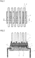
- FIG. 1 is a top view illustrating a semiconductor device using a radiator according to this embodiment
- FIG. 2 is a cross-sectional view taken along a line A-A of FIG. 1
- a lead frame 7 is joined to one surface of a radiation fin support base 1 through an insulating resin sheet 10, and the lead frame 7 and the radiation fin support base 1 are electrically insulated from each other.
- the lead frame 7 is soldered to a heater element 9 with a metal wire.
- the radiation fin support base 1, and radiation fins 4 are formed of a member made of copper or aluminum which is high in thermal conductivity.
- a mold resin 6 covers the heater element 9, the lead frame 7, and a metal wire 8, and electrically insulates those respective members from the external.
- the insulating resin sheet 10 is made of epoxy resin mixed with a filler made of silicon or boron nitride particles. It is preferable that the coefficient of linear thermal expansion of the insulating resin sheet 10 is smaller than the coefficient of linear thermal expansion of the radiation fin support base 1.
- the other surface of the radiation fin support base 1 is formed with plural parallel fin grooves 2, and the radiation fins 4 are installed in the fin grooves 2.
- FIG. 3 is a front view illustrating a radiator according to a first embodiment not part of the present invention.
- FIG. 3(a) is a diagram illustrating a state in which one of the radiation fins 4 is installed in each of the plural parallel fin grooves 2 formed in the radiation fin support base 1.
- a first projection 3 having a predetermined height is exposed from a bottom surface of each fin groove 2.
- the height of the first projection 3 is configured to be lower than an upper end of each fin groove 2. For that reason, even in a state where the radiation fins 4 is inclined obliquely with respect to a height direction of the fin grooves 2, the radiation fins 4 can be inserted into the fin grooves 2 without any interference with the fin grooves 2 or the first projections 3. This makes it easy to insert the radiation fins 4 in a process of manufacturing the radiator.
- FIG. 3(b) is a diagram illustrating a state in which the first projections 3 are tilted toward the radiation fins 4 side by press work, and each of the radiation fins 4 is swaged between a top of the first projection 3 and a side surface of the fin groove 2.
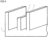
- FIG. 4 is a perspective view of the radiation fin support base 1, the fin groove 2, and the first projection 3.
- each of the fin grooves 2 is formed in a cuboidal shape.
- each of the first projections 3 is formed from the bottom of each fin groove 2 in a cuboidal shape.
- FIG. 5 is a cross-sectional view taken along a line B-B of FIG. 3(a)
- FIG. 6 is a cross-sectional view taken along a line C-C of FIG. 3(a) .
- a longitudinal length of the first projections 3 and a longitudinal length of the fin grooves 2 are identical with a longitudinal length of the radiation fin support base 1.
- a method of manufacturing the radiator according to the first embodiment includes the following manufacturing processes. That is, the method undergoes a process of forming the plural parallel fin grooves 2 to one surface of the radiation fin support base 1, the first projections 3 within the respective fin grooves 2 through the die cast molding or the extrusion molding at the same time. Then, the method undergoes a process of installing one radiation fin 4 in each of the fin grooves 2.
- the method undergoes a process of inserting a press blade 5 between one side surface of the fin groove 2 where the radiation fin 4 is not installed and the first projection 3 and weighting the press blade 5 by a press machine, thereby tilting the first projection 3 toward the radiation fin 4 side, and pushing the top of the first projection 3 against one side surface of the radiation fin 4 to swage the radiation fin. Accordingly, the radiation fin 4 is fixed between the side surface of the fin groove 2 and the top of the first projection 3.
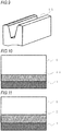
- FIG. 7 is a diagram illustrating a process of tilting the first projections 3 by using the press blade 5 among the above processes.
- the tip of the press blade 5 in order to easily inserting the press blade 5 between the first projection 3 and the fin groove 2, it is desirable that the tip of the press blade 5 is shaped so that a width of the press blade 5 is narrowed toward the tip thereof as illustrated in FIG. 7 .
- the press blade 5 (or a swaging jig) is inserted between one side surface of the fin groove 2 where the radiation fin 4 is not installed and the first projection 3, and the first projection 3 is tilted toward the radiation fin 4 side. More specifically, as illustrated in FIG. 7(b) , the press blade 5 is inserted between one side surface of the fin groove 2 where the radiation fin 4 is not installed and the first projection 3, and then pressed by the press machine.
- the first projections 3 are made of metal large in plasticity such as copper or aluminum, each of the first projections 3 is deformed by pressing through the press machine, and tilted toward the radiation fin 4 side according to the shape of the tip of the press blade 5.
- the tip of the press blade 5 is abutted against a lower end of the fin groove 2, and stops.
- the top of the first projection 3 presses the radiation fin 4 toward the side surface of the fin groove 2.
- the radiation fin 4 is swaged between the top of the first projection 3 and the side surface of the fin groove 2.
- the top of the first projection 3 is dug into the side surface of the radiation fin 4 while maintaining an uprightness of the radiation fin 4.
- the shape of the tip of the press blade 5 and the amount of stroke of the press blade are determined in advance so that a depression 13 can be formed to the side surface of the radiation fin 4. This makes it possible to easily manage the amount of tilt of the first projection 3 by the amount of stroke of the press blade 5. Further, it can be easily determined whether the press work has been normally conducted, or not, by visually inspecting the side surface of the radiation fin 4.
- the press weight exerted on the press blade 5 when tilting the first projection 3 is a sum of a force component in a direction along which the press blade 5 is advanced and a force component in a perpendicular direction, that is, in a direction of widening a width between the first projection 3 and the fin groove 2.
- the first projection 3 can be formed in a trapezoidal shape so that the width thereof is increased more from the top toward the bottom. With this configuration, even if the position of the press blade 5 is slightly displaced from between the fin groove 2 and the first projection 3 when the press blade 5 is inserted into the fin groove 2, the first projection 3 can be prevented from performing buckling distortion. As a result, the amount of widening of the width between the fin groove 2 and the first projection 3 can been ensured, and the radiation fin 4 can be normally swaged.
- the press blade 5 (or a swaging jig) is inserted between a side surface of the fin groove 2 where the radiation fin 4 is not installed and the first projection 3, and the first projection 3 is tilted toward the radiation fin 4 side.
- the radiation fin 4 is swaged between the top of the first projection 3 and the side surface of the fin groove 2.
- FIG. 8 is a front view illustrating a radiator according to a second embodiment not part of the present invention.
- the same configurations as those in FIG. 3 are denoted by identical symbols, and their description will be omitted. Differences from the first embodiment reside in that two radiation fins are installed in one fin groove and in the shape of the projections.
- FIG. 8(a) is a diagram illustrating a state in which two radiation fins 4 are installed in each of the plural parallel fin grooves 2 formed in the radiation fin support base 1. Also, a biforked second projection 11 having a predetermined height is exposed from the bottom surface of each fin groove 2 substantially in the center thereof. This embodiment is identical with the first embodiment in that the height of the second projection 11 is configured to be lower than the upper end of each fin groove 2.
- FIG. 8(b) is a diagram illustrating a state in which a width of a recess of the biforked tip of the second projection 11 is widened by the press work, and the radiation fin 4 is swaged between the top of the second projection 11 and the side surface of the fin groove 2.
- FIG. 9 is a perspective view of the second projection 11.
- each shape of the biforked tip portion of the second projection 11 is shaped into such a trapezoid that the width thereof is increased from the top of the second projection 11 toward the bottom.
- each shape of the biforked tip portion of the second projection 11 may be rectangular.
- FIG. 10 is a cross-sectional view taken along a line B-B of FIG. 8(a)
- FIG. 11 is a cross-sectional view taken along a line C-C of FIG. 8(a) .
- the same configurations as those in FIGS. 5 and 6 are denoted by identical symbols, and their description will be omitted. From both drawings, in the second embodiment, the respective lengths of the second projections 11 and the fin grooves 2 in a longitudinal direction of the grooves are identical with the length of the radiation fin support base 1 in the longitudinal direction of the grooves.
- a method of manufacturing the radiator according to the second embodiment includes the following manufacturing processes. That is, the method undergoes a process of forming the plural parallel fin grooves 2 on one surface of the radiation fin support base 1, and at the same time, forming the second projections 11 within the respective fin grooves 2 so that the tips thereof are biforked.
- the radiation fin support base 1, the fin grooves 2, and the second projection 11 are each formed by the die cast molding or the extrusion molding as in the first embodiment. Then, the method undergoes a process of installing two radiation fins in each of the fin grooves 2.
- the method undergoes a process of inserting the press blade 5 into the recess of the biforked tip of each second projection 11, and weighting the press blade 5 by the press machine, thereby pushing the top of the second projection 11 against one side surface of each radiation fin 4 to swage the radiation fin. Accordingly, each radiation fin 4 is fixed between the side surface of the fin groove 2 and the top of the second projection 11.
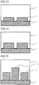
- FIG. 12 is a diagram illustrating a process of widening the biforked tip of each second projection 11 by using the press blade 5 among the above processes.
- the same configurations as those in FIG. 7 are denoted by identical symbols, and their description will be omitted.
- the press blade 5 (or the swaging jig) is inserted into a recess of the biforked tip of the second projection 11. Thereafter, the press blade 5 is further weighted, and advanced until the press blade 5 is abutted against the bottom of the biforked tip of the second projection 11.
- the second projections 11 are made of metal large in plasticity such as copper or aluminum as with the first projections 3, each of the second projections 11 is deformed, and as illustrated in FIG. 12(b) , the width of the tip of the second projection 11 is widened according to the shape of the tip of the press blade 5.
- the radiation fin 4 is swaged between the top of the first projection 3 and the side surface of the fin groove 2.
- the tip of the press blade 5 when the tip of the press blade 5 is abutted against a bottom of the biforked tip of the second projection 11 and stops, as illustrated in FIG. 12(c) , the top of the second projection 11 is dug into the side surface of the radiation fin 4 while maintaining an uprightness of the radiation fin 4.
- the shape of the tip of the press blade 5 and the amount of stroke of the press blade are determined in advance so that the depression 13 can be formed to the side surface of the radiation fin 4. This makes it possible to easily manage the amount of widening of the width of the biforked tip of the second projection 11 by the amount of stroke of the press blade 5. Further, it can be easily determined whether the press work has been normally conducted, or not, by visually inspecting the side surface of the radiation fin 4.
- the press blade 5 (or the swaging jig) is inserted into the recess of the biforked tip of the second projection 11, and the width of the tip of the second projection 11 is widened so that one top of the biforked second projection 11 pushes the radiation fin 4 against the side surface of the fin groove 2. Therefore, the radiation fin 4 is swaged between the top of the first projection 3 and the side surface of the fin groove 2.
- the thermal resistance between the radiation fins and the radiation fin support base can be reduced, thereby enhancing the radiation effect.
- the biforked tip is used as the second projection 11, but instead of the above configuration, two of the first projections 3 used in the first embodiment may be arranged substantially at the center of the fin groove 3.
- the respective lengths of the first projections 3, the second projections 11, and the fin grooves 2 in the longitudinal direction of the grooves are identical with the length of the radiation fin support base 1 in the longitudinal direction of the grooves, and the respective members are successively formed.
- the first projections 3 and the fin grooves 2 in the first embodiment are divided in the longitudinal direction of the grooves, and the divided first projections 3 and the divided fin grooves 2 each having the same length are paired.
- FIG. 13 is a cross-sectional view taken along a line B-B of FIG. 3(a)
- FIG. 14 is a cross-sectional view taken along a line C-C of FIG. 3(a) .
- the same configurations as those in FIGS. 5 and 6 are indicated by identical symbols, and their description will be omitted. From those drawings, in the third embodiment, the first projections 3 and the fin grooves 2 are each divided into two pieces in the longitudinal direction of the grooves, and the divided first projections 3 and the divided fin grooves 2 each having the same length are paired with each other.
- the divided surfaces of the first projections 3 and the fin grooves 2 are formed by a die as with the first projections 3 and the fin grooves 2.
- the divided surfaces are formed by a cutting work after molding.
- the fin grooves 2, the first projections 3, or the radiation fins 4 are deformed, and the contact surface of each radiation fin 4 and the side surface of each fin groove 2 and the contact surface of each radiation fin 4 and the top of each first projection 3 become smaller in contact area. This makes a thermal resistance between the radiation fins 4 and the fin grooves 2 larger, resulting in a risk that the radiation effect is deteriorated.
- each of the fin groove 2 and the first projection 3 is divided into two pieces in the longitudinal direction of the groove whereby a length of each of the fin groove and the projection is shortened.
- the respective expansion and contraction amounts can be reduced to decrease the absolute value of the stress.
- the press weight can be further reduced.
- the respective expansion and contraction amounts of the fin grooves 2 and the first projections 3 can be reduced even in the environment where the ambient temperature is extremely low. Also, the large contact areas of the contact surface of each radiation fin 4 and the side surface of each fin groove 2 and the contact surface of each radiation fin 4 and the top of each first projection 3 can be ensured. For that reason, the thermal resistance between the radiation fins 4 and the fin grooves 2 under the above environment can be prevented from increasing.
- the fin grooves 2 and the first projections 3 are each divided into two pieces in the longitudinal direction of the grooves.
- each of the fin grooves 2 and the first projections 3 can be divided into, for example, three pieces in the longitudinal direction of the grooves. Further, the respective lengths of the divided fin grooves and projections can be changed.
- FIG. 15 is a cross-sectional view taken along the line B-B of FIG. 8(a)
- FIG. 16 is a diagram illustrating a part of a front view of a radiator according to the fourth embodiment.
- the same configurations as those in FIGS. 8 and 12 are indicated by identical symbols, and their description will be omitted.
- the fin grooves 2 are each divided into three pieces in the longitudinal direction of the grooves.
- the second projections 11 having the same length as that of the fin grooves arranged at both ends of the radiation fin support base 1 among the divided fin grooves 2 is paired with those fin grooves.
- a third projection 12 having the same length as that of the fin groove 2 arranged at the center of the radiation fin support base 1 among the divided fin grooves 2 is paired with the fin groove 2. Further, the third projection 12 is higher in height than the second projections 11. As a result, as illustrated in FIG. 16 , each radiation fin 4 is fixed by projections different in height such as the second projections 11 and the third projection 12.
- the amount of widening of the width of the recess formed to the tip of the second projection 11 is changed due to warpage or dimensional variation of the radiation fin support base 1 or displacement of the press blade.
- the amount of widening of the width of the tip of the second projection 11 is large, the radiation fin 4 will be deformed into a shape like a hiragana "ku" toward the second projection 11 side with the top of the second projection 11 as a base point.
- the contact area of the side surface of the radiation fin 4 and the side surface of the fin groove 2 is reduced, the thermal resistance between the radiation fin 4 and the fin groove 2 becomes large, resulting in a risk that the radiation effect is deteriorated.
- the heights of those three fin grooves 2 are identical with each other.
- the height of the third projection 12 arranged in the center of the radiation fin support base 1 is set to be higher than the height of the second projections 11 arranged at both ends of the radiation fin support base 1.
- the second projections 11 and the third projection 12 swage the radiation fin 4 at respective different positions in the height direction of the radiation fin. For that reason, a stress exerted on the contact surface of the radiation fin 4 with the projection is dispersed on contact areas thereof with the tops of the second projections 11 and the top of the third projection 12, and the radiation fin 4 can be prevented from being deformed into the shape like a hiragana "ku".
- the radiation fin 4 when the radiation fin 4 is inserted between the second projections 11 and the third projection 12 and the fin grooves 2, after the radiation fin 4 is inserted between the third projection 12 higher in the height and the fin groove 2, the radiation fin 4 is inserted between the second projections 11 lower in the height and the fin grooves 2. That is, the radiation fins 4 is inserted between the second projections 11 and the fin grooves 2 in a state where a backlash is suppressed between the third projection 12 and the fin groove 2. As a result, the radiation fin 4 can be easily inserted between the second projections 11 and the third projection 12 and the fin grooves 2.
- the radiation fin 4 when the radiation fin 4 is long, when the radiation fin 4 is inserted between the second projections 11 and the third projection 12 and the fin grooves 2, the radiation fin 4 is tilted, thereby making it difficult to insert the radiation fin 4 between the second projections 11 at both ends of the radiation fin support base.
- the presence of the third projection 12 higher in height can prevent the radiation fin 4 from being tilted as described above, the radiation fin 4 can be easily inserted between the second projections 11 and the third projection 12 and the fin grooves 2.
- the radiator is transported. In this situation, because the height of the third projection 12 is higher, the radiation fins 4 can be prevented from being tilted or falling at the time of transporting the radiator.
- each of the fin grooves 2 is divided into three pieces in the longitudinal direction of the groove, and the second projections 11 lower in the height having the same length as that of the fin grooves arranged at both ends of the radiation fin support base 1 among the divided fin grooves 2 is paired with those fin grooves. Also, the third projection 12 higher in the height having the same length as that of the fin groove 2 arranged at the center of the radiation fin support base 1 among the divided fin grooves 2 is paired with the fin groove 2. As a result, each radiation fin 4 is more surely fixed by the second projections 11 and the third projection 12 and the fin groove 2.
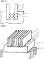
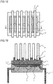
- FIG. 17 is a perspective view illustrating the semiconductor device
- FIG. 18 is a top view illustrating the semiconductor device
- FIG. 19 is a cross-sectional view taken along a line D-D of FIG. 18 .
- the same configurations as those in FIG. 8 are indicated by identical symbols, and their description will be omitted.
- the radiation fin support base 1 covered with a mold resin 6 at the side surface and the bottom surface thereof and the radiation fins 4 are individualized.
- a fin length of the radiation fins 4 can be made longer than a length of the mold resin 6 in a longitudinal direction of the radiation fins 4, and a fin pitch between the adjacent radiation fins can be narrowed, an installation area of the semiconductor device can be reduced.
- a total of the surface areas of the radiation fins 4 in the semiconductor device can be increased, the radiation effect can be enlarged.
- an element that is small in an absolute maximum rating of a junction temperature can be selected as the heater element 9, thereby making it possible to downsize the heater element and reduce the costs.
- the side surface and the bottom surface of the radiation fin support base 1 are covered with the mold resin 6.
- the radiation fin support base 1 is formed by the die cast molding or the extrusion molding as described above, and therefore the radiation fin support base 1 may be warped or swelled. In addition, the radiation fin support base 1 may be expanded and further deformed due to a change in the ambient temperature. For the above reasons, there is a risk that a force for pressing the radiation fins 4 toward the fin grooves 2 is decreased, and the thermal resistance between the radiation fins 4 and the fin grooves 2 is increased to deteriorate the radiation property.
- the side surface and the bottom surface of the radiation fin support base 1 are covered with the mold resin 6. Therefore, the side surface and the bottom surface of the radiation fin support base 1 can be held so as to prevent the radiation fin support base 1 from being expanded and deformed. As a result, the force for pressing the radiation fins 4 toward the fin grooves 2 can be prevented from being decreased, and the radiation property can be prevented from being deteriorated.
Landscapes
- Engineering & Computer Science (AREA)
- Mechanical Engineering (AREA)
- Physics & Mathematics (AREA)
- Thermal Sciences (AREA)
- General Engineering & Computer Science (AREA)
- Cooling Or The Like Of Semiconductors Or Solid State Devices (AREA)
- Cooling Or The Like Of Electrical Apparatus (AREA)
- Condensed Matter Physics & Semiconductors (AREA)
- General Physics & Mathematics (AREA)
- Computer Hardware Design (AREA)
- Microelectronics & Electronic Packaging (AREA)
- Power Engineering (AREA)
- Manufacturing & Machinery (AREA)
- Chemical & Material Sciences (AREA)
- Materials Engineering (AREA)
Description
- The present invention particularly relates to a radiator that is sealed by resin, among radiators each cooling a heater element for use in various devices including a power converter, and a method of manufacturing the radiator.
- Up to now, as a radiator that cools the heater element, heat sinks have been generally widely used. The heat sinks are roughly classified into one heat sink in which radiation fins and a radiation fin support base are integrated together by die cast molding or extrusion molding, and another heat sink in which the radiation fins and the radiation fin support base are individualized and combined together. In the latter, by the radiation fins and the radiation fin support base being individualized, a restriction of strength of a die necessary for the extrusion molding or the die cast molding can be relaxed, and therefore, a fin pitch between the adjacent radiation fins can be narrowed or a radiation fin length can be lengthened. Accordingly, as compared with the former, the latter is effective in reducing costs attributable to a reduction in an installation area of a semiconductor device or a reduction in a size of the heater element.
- Also, there is a swaging method as a method of fitting the radiation fins with the radiation fin support base in a configuration where the radiation fins and the radiation fin support base are individualized and combined together. As this method, for example,
Patent Literature 1 discloses a radiator in which plural grooves are formed in parallel to a plane of the radiation fin support base in advance, side edges of the radiation fins are fixed with the grooves from above, and a tip of a swaging tool is pushed against plural different grooves each formed between the plural adjacent grooves to forcedly narrow the grooves fixed with the side edges of the radiation fins. - Also,
Patent Literature 2 discloses a technique by which the grooves of the radiation fin support base are formed into a taper shape so as to expand from openings of the grooves toward bottoms thereof, and both sides of each groove bottom are rounded. Accordingly, when the radiation fins are swaged in the grooves, the radiation fins are deformed into an expanded taper shape along the groove shape, and pressed and fixed into the grooves.Patent Literature 3 discloses a heat sink in which radiating fins are provided with a conducting surface, with which the fins are attached to a base plate in contact with an integrated circuit. One example of fixing the radiation fins to the base plate includes the insertion of protrusions formed on the base plate into holes in the conducting surface of the radiation fins and the subsequent swaging of the heads of the protrusions.Patent Literature 4 relates to a radiator for a semiconductor device in which radiating fins are inserted in grooves that are continuously formed on the base plate. The fixation of the radiation fins is achieves by cutting and subsequently tilting continuous protrusions that are formed in the grooves.Patent Literatures 5 to 9 relate to heat sinks in which a plurality of radiation fins is inserted into corresponding continuous grooves that are provided on the base plate. With the help of a subsequent processing step performed on the base plate material between the radiation fins, the radiation fins can be fixed to the base plate. -
- Patent Literature 1:
JP-A-2001-102786 page 3,FIG. 8 ) - Patent Literature 2:
JP-A-2002-299864 page 4,FIGS. 1 and6 ) - Patent Literature 3:
US 2007/029068 A1 - Patent Literature 4:
WO 2008/123488 A1 - Patent Literature 5:
US 2002/070005 A1 - Patent Literature 6:
WO 02/41677 A2 - Patent Literature 7:
JP 6-315731 A - Patent Literature 8:
JP 7-161882 A - Patent Literature 9:
JP 57-209729 A - However, in the technique disclosed in the above-mentioned
Patent Literature 1, because the bottoms of the grooves of the radiation fin support base are deformed in a widening direction along a press blade, the radiation fin easily contacts the groove opening, but hardly contacts the groove bottom. As a result, because gaps are liable to be generated between the radiation fins and the grooves, there arises a problem that a thermal resistance between the radiation fins and the radiation fin support base becomes large, and a radiation effect is deteriorated. - Further, in order to fix one radiation fin with the radiation fin support base, the swaging tool needs to broaden two types of grooves, that is, the groove for the radiation fin and the groove for the swaging tool. Therefore, a weight of the swaging tool becomes large. As a result, in order to increase the press weight, a press machine whose frame and motor are large is required. This causes such problems that equipment for swaging the radiation fins in the radiation fin support base becomes large in size, and its facility costs also become high.
- Also, in the technique of the above-mentioned
Patent Literature 2, there is a need to form the grooves of the radiation fin support base into the taper shape so as to expand from the openings toward the bottoms, and round both sides of each groove bottom. Also, when the radiation fins are swaged in the grooves, the shape of the radiation fin is changed by merely pressing a press blade (press blade) into the radiation fins and using the shape of the grooves. Accordingly, there arise a problem that it is difficult to manage the precision of the pressure by which the radiation fins are pressed for securing the high degree of adhesion of the radiation fins and the grooves, the error of the pressure causes the larger thermal resistance, and the radiation effect is deteriorated. - The present invention has been made in view of the above problems, and aims to provide a radiator in which side gaps between surfaces of radiation fins and a radiation fin support base are eliminated to enlarge contact areas therebetween whereby a thermal resistance between the radiation fins and the radiation fin support base can be reduced to enhance a radiation effect, and a press weight when the radiation fins are swaged in the radiation fin support base can be reduced, and a method of manufacturing the radiator.
- According to an aspect of the present invention, there is provided a radiator including the features of
claim 1 and a method for manufacturing a radiator according toclaim 2. - As described above, according to the radiator and the method of mounting the radiator of the present invention, the projections are tilted toward the radiation fin side, and pushes one side surface of the radiation fin. According to this configuration, the other side surface of the radiation fin is pushed toward a side surface of the fin groove so as to eliminate the gap between the side surface of the radiation fin and the fin groove. As a result, because a contact area of the radiation fin and the radiation fin support base is reduced, a thermal resistance between the radiation fin and the radiation fin support base is reduced, thereby enhancing the radiation effect.
- Further, according to the fin groove and the projection each divided in a plurality of pieces in a longitudinal direction of the fin groove, and each of the divided fin grooves and each of the divided projections having a same length in the longitudinal direction of the fin groove and being paired with each other, the respective expansion and contraction amounts of the fin groove and the projection can be reduced even in an environment where the ambient temperature is extremely low. Also, large contact areas of the contact surface of the radiation fin and the side surface of the fin groove and the contact surface of the radiation fin and the top of the projection can be ensured.
-
-
FIG. 1 is a top view illustrating a semiconductor device using a radiator according to the present invention. -
FIG. 2 is a cross-sectional view taken along a line A-A inFIG. 1 in the semiconductor device using a radiator according to the present invention. -
FIG. 3 is a front view illustrating a radiator according to a first embodiment not part of the present invention. -
FIG. 4 is a perspective view illustrating a radiation fin support base, fin grooves, and first projections according to the first embodiment not part of the present invention. -
FIG. 5 is a cross-sectional view taken along a line B-B ofFIG. 3(a) according to the first embodiment not part of the present invention. -
FIG. 6 is a cross-sectional view taken along a line C-C ofFIG. 3(a) according to the first embodiment not part of the present invention. -
FIG. 7 is a diagram illustrating a process of tilting first projections by using a press blade according to the first embodiment not part of the present invention. -
FIG. 8 is a front view illustrating a radiator according to a second embodiment not part of the present invention. -
FIG. 9 is a perspective view illustrating second projections according to the second embodiment not part of the present invention. -
FIG. 10 is a cross-sectional view taken along a line B-B ofFIG. 8(a) according to the second embodiment not part of the present invention. -
FIG. 11 is a cross-sectional view taken along a line C-C ofFIG. 8(a) according to the second embodiment not part of the present invention. -
FIG. 12 is a diagram illustrating a process of widening a biforked tip of each second projection by using the press blade according to the second embodiment not part of the present invention. -
FIG. 13 is a cross-sectional view taken along a line B-B ofFIG. 3(a) according to a third embodiment of the present invention. -
FIG. 14 is a cross-sectional view taken along a line C-C ofFIG. 3(a) according to the third embodiment of the present invention. -
FIG. 15 is a cross-sectional view taken along the line B-B ofFIG. 8(a) according to a fourth embodiment of the present invention. -
FIG. 16 is a diagram illustrating a part of a front view of a radiator according to the fourth embodiment of the present invention. -
FIG. 17 is a perspective view illustrating the semiconductor device using the radiator according to the present invention. -
FIG. 18 is a top view illustrating the semiconductor device using the radiator according to the present invention. -
FIG. 19 is a cross-sectional view taken along a line D-D ofFIG. 18 in the semiconductor device using the radiator according to the present invention. - The embodiment relates to a radiator for efficiently radiating a heat radiated from a heater element used in, for example, a power converting device. The heater element includes, for example, a diode of a converter part that converts an AC into a DC in a power converting device, a bipolar transistor of an inverter part that converts the DC into the AC, and an IGBT, a MOSFET, or a GTO as a switching element. The present invention is not limited to this embodiment.
-
FIG. 1 is a top view illustrating a semiconductor device using a radiator according to this embodiment, andFIG. 2 is a cross-sectional view taken along a line A-A ofFIG. 1 . Referring toFIG. 2 , alead frame 7 is joined to one surface of a radiationfin support base 1 through an insulating resin sheet 10, and thelead frame 7 and the radiationfin support base 1 are electrically insulated from each other. Thelead frame 7 is soldered to aheater element 9 with a metal wire. Also, in order to efficiently radiate a heat from theheater element 9, thelead frame 7, the radiationfin support base 1, andradiation fins 4 are formed of a member made of copper or aluminum which is high in thermal conductivity. - Further, a
mold resin 6 covers theheater element 9, thelead frame 7, and ametal wire 8, and electrically insulates those respective members from the external. Also, in order to provide an insulation property and a high conductivity, the insulating resin sheet 10 is made of epoxy resin mixed with a filler made of silicon or boron nitride particles. It is preferable that the coefficient of linear thermal expansion of the insulating resin sheet 10 is smaller than the coefficient of linear thermal expansion of the radiationfin support base 1. - Also, the other surface of the radiation
fin support base 1 is formed with pluralparallel fin grooves 2, and theradiation fins 4 are installed in thefin grooves 2. -
FIG. 3 is a front view illustrating a radiator according to a first embodiment not part of the present invention.FIG. 3(a) is a diagram illustrating a state in which one of theradiation fins 4 is installed in each of the pluralparallel fin grooves 2 formed in the radiationfin support base 1. Also, afirst projection 3 having a predetermined height is exposed from a bottom surface of eachfin groove 2. In this example, the height of thefirst projection 3 is configured to be lower than an upper end of eachfin groove 2. For that reason, even in a state where theradiation fins 4 is inclined obliquely with respect to a height direction of thefin grooves 2, theradiation fins 4 can be inserted into thefin grooves 2 without any interference with thefin grooves 2 or thefirst projections 3. This makes it easy to insert theradiation fins 4 in a process of manufacturing the radiator. -
FIG. 3(b) is a diagram illustrating a state in which thefirst projections 3 are tilted toward theradiation fins 4 side by press work, and each of theradiation fins 4 is swaged between a top of thefirst projection 3 and a side surface of thefin groove 2.FIG. 4 is a perspective view of the radiationfin support base 1, thefin groove 2, and thefirst projection 3. In the first embodiment, each of thefin grooves 2 is formed in a cuboidal shape. Also, each of thefirst projections 3 is formed from the bottom of eachfin groove 2 in a cuboidal shape. -
FIG. 5 is a cross-sectional view taken along a line B-B ofFIG. 3(a) , andFIG. 6 is a cross-sectional view taken along a line C-C ofFIG. 3(a) . As illustrated in those drawings, in the first embodiment, a longitudinal length of thefirst projections 3 and a longitudinal length of thefin grooves 2 are identical with a longitudinal length of the radiationfin support base 1. - It is desirable that a method of manufacturing the radiator according to the first embodiment includes the following manufacturing processes. That is, the method undergoes a process of forming the plural
parallel fin grooves 2 to one surface of the radiationfin support base 1, thefirst projections 3 within therespective fin grooves 2 through the die cast molding or the extrusion molding at the same time. Then, the method undergoes a process of installing oneradiation fin 4 in each of thefin grooves 2. Thereafter, the method undergoes a process of inserting apress blade 5 between one side surface of thefin groove 2 where theradiation fin 4 is not installed and thefirst projection 3 and weighting thepress blade 5 by a press machine, thereby tilting thefirst projection 3 toward theradiation fin 4 side, and pushing the top of thefirst projection 3 against one side surface of theradiation fin 4 to swage the radiation fin. Accordingly, theradiation fin 4 is fixed between the side surface of thefin groove 2 and the top of thefirst projection 3. -
FIG. 7 is a diagram illustrating a process of tilting thefirst projections 3 by using thepress blade 5 among the above processes. In this example, in order to easily inserting thepress blade 5 between thefirst projection 3 and thefin groove 2, it is desirable that the tip of thepress blade 5 is shaped so that a width of thepress blade 5 is narrowed toward the tip thereof as illustrated inFIG. 7 . Also, in order to make it hard to break thepress blade 5, and in order to increase a press blade angle, it is desirable to partially flatten the tip of thepress blade 5. From the above viewpoints, it is desirable that thepress blade 5 is trapezoidally shaped so that the width of thepress blade 5 is narrowed toward the tip thereof. - As illustrated in
FIG. 7(a) , the press blade 5 (or a swaging jig) is inserted between one side surface of thefin groove 2 where theradiation fin 4 is not installed and thefirst projection 3, and thefirst projection 3 is tilted toward theradiation fin 4 side. More specifically, as illustrated inFIG. 7(b) , thepress blade 5 is inserted between one side surface of thefin groove 2 where theradiation fin 4 is not installed and thefirst projection 3, and then pressed by the press machine. In this example, because thefirst projections 3 are made of metal large in plasticity such as copper or aluminum, each of thefirst projections 3 is deformed by pressing through the press machine, and tilted toward theradiation fin 4 side according to the shape of the tip of thepress blade 5. Thereafter, the tip of thepress blade 5 is abutted against a lower end of thefin groove 2, and stops. With this operation, the top of thefirst projection 3 presses theradiation fin 4 toward the side surface of thefin groove 2. For that reason, as illustrated inFIG. 7(b) , theradiation fin 4 is swaged between the top of thefirst projection 3 and the side surface of thefin groove 2. - Through the above processes, there can be obtained a radiation fin attaching structure having high adhesion between the
radiation fins 4 and the side surfaces of thefin grooves 2. As a result, because large contact areas of theradiation fins 4 with thefin grooves 2 can be ensured, the thermal resistance between the radiation fins and the radiation fin support base can be reduced, thereby enhancing the radiation effect. - Also, in this situation, as illustrated in
FIG. 7(c) , the top of thefirst projection 3 is dug into the side surface of theradiation fin 4 while maintaining an uprightness of theradiation fin 4. The shape of the tip of thepress blade 5 and the amount of stroke of the press blade are determined in advance so that adepression 13 can be formed to the side surface of theradiation fin 4. This makes it possible to easily manage the amount of tilt of thefirst projection 3 by the amount of stroke of thepress blade 5. Further, it can be easily determined whether the press work has been normally conducted, or not, by visually inspecting the side surface of theradiation fin 4. - The press weight exerted on the
press blade 5 when tilting thefirst projection 3 is a sum of a force component in a direction along which thepress blade 5 is advanced and a force component in a perpendicular direction, that is, in a direction of widening a width between thefirst projection 3 and thefin groove 2. In this case, if an angle of the tip of thepress blade 5 to the direction along which thepress blade 5 is advanced is obtuse (that is, (force component in the direction along which thepress blade 5 is advanced) < (force component in the perpendicular direction)), there has been generally known that thefirst projections 3 is not tilted from an interface thereof with the radiationfin support base 1, but is deformed toward theradiation fin 4 side from, for example, the tip portion of thefirst projection 3, that is, buckling distortion. If thefirst projection 3 performs buckling distortion, because the amount of widening of the width between thefin groove 2 and thefirst projection 3 is reduced, there is a risk that theradiation fin 4 is not normally swaged. - Under the circumstances, the
first projection 3 can be formed in a trapezoidal shape so that the width thereof is increased more from the top toward the bottom. With this configuration, even if the position of thepress blade 5 is slightly displaced from between thefin groove 2 and thefirst projection 3 when thepress blade 5 is inserted into thefin groove 2, thefirst projection 3 can be prevented from performing buckling distortion. As a result, the amount of widening of the width between thefin groove 2 and thefirst projection 3 can been ensured, and theradiation fin 4 can be normally swaged. - With the above configuration, according to the first embodiment, the press blade 5 (or a swaging jig) is inserted between a side surface of the
fin groove 2 where theradiation fin 4 is not installed and thefirst projection 3, and thefirst projection 3 is tilted toward theradiation fin 4 side. As a result, theradiation fin 4 is swaged between the top of thefirst projection 3 and the side surface of thefin groove 2. With this configuration, there can be obtained a radiation fin attaching structure improved in the adhesion of theradiation fins 4 and the side surfaces of thefin grooves 2. As a result, because large contact areas of the radiation fins with the fin grooves can be ensured, the thermal resistance between the radiation fins and the radiation fin support base can be reduced, thereby enhancing the radiation effect. -
FIG. 8 is a front view illustrating a radiator according to a second embodiment not part of the present invention. The same configurations as those inFIG. 3 are denoted by identical symbols, and their description will be omitted. Differences from the first embodiment reside in that two radiation fins are installed in one fin groove and in the shape of the projections. -
FIG. 8(a) is a diagram illustrating a state in which tworadiation fins 4 are installed in each of the pluralparallel fin grooves 2 formed in the radiationfin support base 1. Also, a biforked second projection 11 having a predetermined height is exposed from the bottom surface of eachfin groove 2 substantially in the center thereof. This embodiment is identical with the first embodiment in that the height of the second projection 11 is configured to be lower than the upper end of eachfin groove 2. - Also,
FIG. 8(b) is a diagram illustrating a state in which a width of a recess of the biforked tip of the second projection 11 is widened by the press work, and theradiation fin 4 is swaged between the top of the second projection 11 and the side surface of thefin groove 2.FIG. 9 is a perspective view of the second projection 11. InFIG. 9 , each shape of the biforked tip portion of the second projection 11 is shaped into such a trapezoid that the width thereof is increased from the top of the second projection 11 toward the bottom. Alternatively, as in the first embodiment, each shape of the biforked tip portion of the second projection 11 may be rectangular. -
FIG. 10 is a cross-sectional view taken along a line B-B ofFIG. 8(a) , andFIG. 11 is a cross-sectional view taken along a line C-C ofFIG. 8(a) . The same configurations as those inFIGS. 5 and 6 are denoted by identical symbols, and their description will be omitted. From both drawings, in the second embodiment, the respective lengths of the second projections 11 and thefin grooves 2 in a longitudinal direction of the grooves are identical with the length of the radiationfin support base 1 in the longitudinal direction of the grooves. - It is desirable that a method of manufacturing the radiator according to the second embodiment includes the following manufacturing processes. That is, the method undergoes a process of forming the plural
parallel fin grooves 2 on one surface of the radiationfin support base 1, and at the same time, forming the second projections 11 within therespective fin grooves 2 so that the tips thereof are biforked. In this example, the radiationfin support base 1, thefin grooves 2, and the second projection 11 are each formed by the die cast molding or the extrusion molding as in the first embodiment. Then, the method undergoes a process of installing two radiation fins in each of thefin grooves 2. Thereafter, the method undergoes a process of inserting thepress blade 5 into the recess of the biforked tip of each second projection 11, and weighting thepress blade 5 by the press machine, thereby pushing the top of the second projection 11 against one side surface of eachradiation fin 4 to swage the radiation fin. Accordingly, eachradiation fin 4 is fixed between the side surface of thefin groove 2 and the top of the second projection 11. With the above manufacturing method, in order to fix two radiation fins, only one recess of the tip of the second projection 11 needs to be swaged by the press blade 4 (or swage jig). Therefore, as compared with the conventional art, the number of press blades used in the process of manufacturing the radiator can be reduced. As a result, since the weight when conducting the press work can be reduced, the press machine can be downsized. -
FIG. 12 is a diagram illustrating a process of widening the biforked tip of each second projection 11 by using thepress blade 5 among the above processes. The same configurations as those inFIG. 7 are denoted by identical symbols, and their description will be omitted. As illustrated inFIG. 12(a) , the press blade 5 (or the swaging jig) is inserted into a recess of the biforked tip of the second projection 11. Thereafter, thepress blade 5 is further weighted, and advanced until thepress blade 5 is abutted against the bottom of the biforked tip of the second projection 11. In this example, because the second projections 11 are made of metal large in plasticity such as copper or aluminum as with thefirst projections 3, each of the second projections 11 is deformed, and as illustrated inFIG. 12(b) , the width of the tip of the second projection 11 is widened according to the shape of the tip of thepress blade 5. As a result, because one top of the biforked second projection 11 pushes theradiation fin 4 against the side surface of thefin groove 2, theradiation fin 4 is swaged between the top of thefirst projection 3 and the side surface of thefin groove 2. With the above configuration, there can be obtained a radiation fin attaching structure improved in the adhesion of theradiation fins 4 and the side surfaces of thefin grooves 2. As a result, because large contact areas of theradiation fins 4 with thefin grooves 2 can be ensured, the thermal resistance between the radiation fins and the radiation fin support base can be reduced, thereby enhancing the radiation effect. - Also, as described above, when the tip of the
press blade 5 is abutted against a bottom of the biforked tip of the second projection 11 and stops, as illustrated inFIG. 12(c) , the top of the second projection 11 is dug into the side surface of theradiation fin 4 while maintaining an uprightness of theradiation fin 4. The shape of the tip of thepress blade 5 and the amount of stroke of the press blade are determined in advance so that thedepression 13 can be formed to the side surface of theradiation fin 4. This makes it possible to easily manage the amount of widening of the width of the biforked tip of the second projection 11 by the amount of stroke of thepress blade 5. Further, it can be easily determined whether the press work has been normally conducted, or not, by visually inspecting the side surface of theradiation fin 4. - With the above configuration, according to the second embodiment, the press blade 5 (or the swaging jig) is inserted into the recess of the biforked tip of the second projection 11, and the width of the tip of the second projection 11 is widened so that one top of the biforked second projection 11 pushes the
radiation fin 4 against the side surface of thefin groove 2. Therefore, theradiation fin 4 is swaged between the top of thefirst projection 3 and the side surface of thefin groove 2. With this configuration, there can be obtained a radiation fin attaching structure improved in the adhesion of theradiation fins 4 and the side surfaces of thefin grooves 2. As a result, because large contact areas of theradiation fins 4 with thefin grooves 2 can be ensured, the thermal resistance between the radiation fins and the radiation fin support base can be reduced, thereby enhancing the radiation effect. - Further, when the above two
radiation fins 4 are swaged between the tops of the second projection 11 and the side surfaces of thefin groove 2, only one portion of the recess of the biforked tip of the second projection 11 needs to be swaged by the press blade 4 (or the swage jig). As a result, as compared with the conventional art, the number of press blades used in the process of manufacturing the radiator can be reduced. As a result, since the weight when conducting the press work can be reduced, the press machine can be downsized. - In the second embodiment, the biforked tip is used as the second projection 11, but instead of the above configuration, two of the
first projections 3 used in the first embodiment may be arranged substantially at the center of thefin groove 3. - In the first embodiment and the second embodiment, the respective lengths of the
first projections 3, the second projections 11, and thefin grooves 2 in the longitudinal direction of the grooves are identical with the length of the radiationfin support base 1 in the longitudinal direction of the grooves, and the respective members are successively formed. In a third embodiment, for example, thefirst projections 3 and thefin grooves 2 in the first embodiment are divided in the longitudinal direction of the grooves, and the dividedfirst projections 3 and the dividedfin grooves 2 each having the same length are paired. -
FIG. 13 is a cross-sectional view taken along a line B-B ofFIG. 3(a) , andFIG. 14 is a cross-sectional view taken along a line C-C ofFIG. 3(a) . The same configurations as those inFIGS. 5 and 6 are indicated by identical symbols, and their description will be omitted. From those drawings, in the third embodiment, thefirst projections 3 and thefin grooves 2 are each divided into two pieces in the longitudinal direction of the grooves, and the dividedfirst projections 3 and the dividedfin grooves 2 each having the same length are paired with each other. - In the third embodiment, if the
first projections 3 and thefin grooves 2 are formed by die cast molding, the divided surfaces of thefirst projections 3 and thefin grooves 2 are formed by a die as with thefirst projections 3 and thefin grooves 2. On the other hand, when thefirst projections 3 and thefin grooves 2 are formed by the extrusion molding, the divided surfaces are formed by a cutting work after molding. - Particularly under an environment in which an ambient temperature is extremely low, a stress is applied to a contact surface of each
radiation fin 4 and the side surface of eachfin groove 2 and a contact surface of eachradiation fin 4 and the top of eachfirst projection 3 due to respective linear expansion differences of thefin grooves 2, thefirst projections 3, and theradiation fins 4. In particular, when the lengths of thefin grooves 2 and thefirst projections 3 are long as in the first embodiment and the second embodiment, because an absolute value of expansion and contraction amount becomes large, the stress is increased. As a result, thefin grooves 2, thefirst projections 3, or theradiation fins 4 are deformed, and the contact surface of eachradiation fin 4 and the side surface of eachfin groove 2 and the contact surface of eachradiation fin 4 and the top of eachfirst projection 3 become smaller in contact area. This makes a thermal resistance between theradiation fins 4 and thefin grooves 2 larger, resulting in a risk that the radiation effect is deteriorated. - On the other hand, in the third embodiment, each of the
fin groove 2 and thefirst projection 3 is divided into two pieces in the longitudinal direction of the groove whereby a length of each of the fin groove and the projection is shortened. As a result, the respective expansion and contraction amounts can be reduced to decrease the absolute value of the stress. With the above configuration, even in an environment where the ambient temperature is extremely low, the large contact areas of the contact surface of eachradiation fin 4 and the side surface of eachfin groove 2 and the contact surface of eachradiation fin 4 and the top of eachfirst projection 3 can be ensured. This makes it possible to prevent the thermal resistance between theradiation fins 4 and thefin grooves 2 under the above environment from increasing. - Further, when the
first projection 3 is divided into two pieces, because the weight necessary when subjecting thefirst projections 3 to the press work becomes small as described above, the press weight can be further reduced. - With the above configuration, according to the third embodiment, when the
fin grooves 2 and thefirst projections 3 are each divided into two pieces in the longitudinal direction of the grooves, the respective expansion and contraction amounts of thefin grooves 2 and thefirst projections 3 can be reduced even in the environment where the ambient temperature is extremely low. Also, the large contact areas of the contact surface of eachradiation fin 4 and the side surface of eachfin groove 2 and the contact surface of eachradiation fin 4 and the top of eachfirst projection 3 can be ensured. For that reason, the thermal resistance between theradiation fins 4 and thefin grooves 2 under the above environment can be prevented from increasing. - In the third embodiment, the
fin grooves 2 and thefirst projections 3 are each divided into two pieces in the longitudinal direction of the grooves. However, each of thefin grooves 2 and thefirst projections 3 can be divided into, for example, three pieces in the longitudinal direction of the grooves. Further, the respective lengths of the divided fin grooves and projections can be changed. -
FIG. 15 is a cross-sectional view taken along the line B-B ofFIG. 8(a) , andFIG. 16 is a diagram illustrating a part of a front view of a radiator according to the fourth embodiment. The same configurations as those inFIGS. 8 and12 are indicated by identical symbols, and their description will be omitted. FromFIG. 15 , in the fourth embodiment, thefin grooves 2 are each divided into three pieces in the longitudinal direction of the grooves. The second projections 11 having the same length as that of the fin grooves arranged at both ends of the radiationfin support base 1 among the dividedfin grooves 2 is paired with those fin grooves. Also, a third projection 12 having the same length as that of thefin groove 2 arranged at the center of the radiationfin support base 1 among the dividedfin grooves 2 is paired with thefin groove 2. Further, the third projection 12 is higher in height than the second projections 11. As a result, as illustrated inFIG. 16 , eachradiation fin 4 is fixed by projections different in height such as the second projections 11 and the third projection 12. - In this example, when the
radiation fin 4 is inserted between thefin groove 2 and the second projection 11 and the top of the second projection 11 is press-weighted, the amount of widening of the width of the recess formed to the tip of the second projection 11 is changed due to warpage or dimensional variation of the radiationfin support base 1 or displacement of the press blade. For example, if the amount of widening of the width of the tip of the second projection 11 is large, theradiation fin 4 will be deformed into a shape like a hiragana "ku" toward the second projection 11 side with the top of the second projection 11 as a base point. As a result, because the contact area of the side surface of theradiation fin 4 and the side surface of thefin groove 2 is reduced, the thermal resistance between theradiation fin 4 and thefin groove 2 becomes large, resulting in a risk that the radiation effect is deteriorated. - On the other hand, in the fourth embodiment, the heights of those three
fin grooves 2 are identical with each other. However, the height of the third projection 12 arranged in the center of the radiationfin support base 1 is set to be higher than the height of the second projections 11 arranged at both ends of the radiationfin support base 1. The second projections 11 and the third projection 12 swage theradiation fin 4 at respective different positions in the height direction of the radiation fin. For that reason, a stress exerted on the contact surface of theradiation fin 4 with the projection is dispersed on contact areas thereof with the tops of the second projections 11 and the top of the third projection 12, and theradiation fin 4 can be prevented from being deformed into the shape like a hiragana "ku". - Also, when the
radiation fin 4 is inserted between the second projections 11 and the third projection 12 and thefin grooves 2, after theradiation fin 4 is inserted between the third projection 12 higher in the height and thefin groove 2, theradiation fin 4 is inserted between the second projections 11 lower in the height and thefin grooves 2. That is, theradiation fins 4 is inserted between the second projections 11 and thefin grooves 2 in a state where a backlash is suppressed between the third projection 12 and thefin groove 2. As a result, theradiation fin 4 can be easily inserted between the second projections 11 and the third projection 12 and thefin grooves 2. In particular, when theradiation fin 4 is long, when theradiation fin 4 is inserted between the second projections 11 and the third projection 12 and thefin grooves 2, theradiation fin 4 is tilted, thereby making it difficult to insert theradiation fin 4 between the second projections 11 at both ends of the radiation fin support base. However, according to the fourth embodiment, because the presence of the third projection 12 higher in height can prevent theradiation fin 4 from being tilted as described above, theradiation fin 4 can be easily inserted between the second projections 11 and the third projection 12 and thefin grooves 2. - Further, in the process of manufacturing the radiator, after the
radiation fins 4 are inserted between the second projections 11 and the third projection 12 and thefin grooves 2, the radiator is transported. In this situation, because the height of the third projection 12 is higher, theradiation fins 4 can be prevented from being tilted or falling at the time of transporting the radiator. - With the above configuration, according to the fourth embodiment, each of the
fin grooves 2 is divided into three pieces in the longitudinal direction of the groove, and the second projections 11 lower in the height having the same length as that of the fin grooves arranged at both ends of the radiationfin support base 1 among the dividedfin grooves 2 is paired with those fin grooves. Also, the third projection 12 higher in the height having the same length as that of thefin groove 2 arranged at the center of the radiationfin support base 1 among the dividedfin grooves 2 is paired with thefin groove 2. As a result, eachradiation fin 4 is more surely fixed by the second projections 11 and the third projection 12 and thefin groove 2. - One example of a semiconductor device using the radiator according to the first to fourth embodiments will be described hereinafter.
FIG. 17 is a perspective view illustrating the semiconductor device, andFIG. 18 is a top view illustrating the semiconductor device.FIG. 19 is a cross-sectional view taken along a line D-D ofFIG. 18 . The same configurations as those inFIG. 8 are indicated by identical symbols, and their description will be omitted. - In the semiconductor device, the radiation
fin support base 1 covered with amold resin 6 at the side surface and the bottom surface thereof and theradiation fins 4 are individualized. With this configuration, because a fin length of theradiation fins 4 can be made longer than a length of themold resin 6 in a longitudinal direction of theradiation fins 4, and a fin pitch between the adjacent radiation fins can be narrowed, an installation area of the semiconductor device can be reduced. Also, since a total of the surface areas of theradiation fins 4 in the semiconductor device can be increased, the radiation effect can be enlarged. As a result, for example, an element that is small in an absolute maximum rating of a junction temperature can be selected as theheater element 9, thereby making it possible to downsize the heater element and reduce the costs. - Also, the side surface and the bottom surface of the radiation
fin support base 1 are covered with themold resin 6. The radiationfin support base 1 is formed by the die cast molding or the extrusion molding as described above, and therefore the radiationfin support base 1 may be warped or swelled. In addition, the radiationfin support base 1 may be expanded and further deformed due to a change in the ambient temperature. For the above reasons, there is a risk that a force for pressing theradiation fins 4 toward thefin grooves 2 is decreased, and the thermal resistance between theradiation fins 4 and thefin grooves 2 is increased to deteriorate the radiation property. - On the other hand, the side surface and the bottom surface of the radiation
fin support base 1 are covered with themold resin 6. Therefore, the side surface and the bottom surface of the radiationfin support base 1 can be held so as to prevent the radiationfin support base 1 from being expanded and deformed. As a result, the force for pressing theradiation fins 4 toward thefin grooves 2 can be prevented from being decreased, and the radiation property can be prevented from being deteriorated. -
- 1 radiation fin support base
- 2 fin groove
- 3 first projection
- 4 radiation fin
- 5 press blade
- 9 heater element
- 11 second projection
- 12 third projection
Claims (2)
- A radiator comprising:a plurality of radiation fins (4); anda radiation fin support base (1) having a heater element mounted to one surface thereof and a plurality of parallel fin grooves (2), to which the radiation fins are installed, and a projection (11, 12), which exposes from a bottom surface of the fin groove (2) by a predetermined height and is configured to fix the radiation fin (4), formed to the other surface thereof,wherein the fin groove (2) and the projection (11, 12) are each divided in a plurality of pieces in a longitudinal direction of the fin groove (2), and each of the divided fin grooves and each of the divided projections (11, 12) have a same length in the longitudinal direction of the fin groove (2) and are paired with each other,characterized in thata top of the projection is pushing one side surface of the radiation fin (4) to push the other side surface of the radiation fin (4) toward a side surface of the fin groove (2), thereby fixing the radiation fin (4) between the top of the projection (11, 12) and the side surface of the fin groove (2),and in that the projection (11, 12) is divided into three pieces, andwherein, among the divided projections (11, 12), a height of the projection (12) arranged at the center of the radiation fin support base (1) is higher than a height of the projections (11) arranged at both ends of the radiation fin support base (1).
- A method of manufacturing a radiator, comprising the steps of:forming, to another surface a radiation fin support base (1) having a heater element (9) mounted to one surface thereof, a plurality of parallel fin grooves (2) to which radiation fins (4) are installed and a projection (11, 12) which exposes from a bottom surface of the fin groove (2) by a predetermined height and is configured to fix the radiation fin (4), the fin groove (2) and the projection (11, 12) formed by dividing each of the fin groove (2) and the projection (11, 12) into three pieces in a longitudinal direction of the fin groove (2) and arranging the divided fin grooves (2) to be paired with the divided projections (11, 12),when mounting the radiation fin (4) in the fin groove (2), inserting the radiation fin between the divided projections (11, 12) and the divided fin grooves arranged at both ends of the fin groove (2), after the radiation fin (4) is inserted between the divided projection (11, 12) and the divided fin groove arranged at the center of the fin groove (2), characterized in thata height of a divided projection (11, 12) arranged at the center of the fin groove (2) is formed to be higher than a height of divided projections (11, 12) arranged at both ends of the fin groove (2); and in that the method further comprises the steps ofabutting a press blade (5) against a top of the radiation fin, and at the same time, inserting the press blade (5) between a side surface of the fin groove where the radiation fin (4) is not installed and the projection (11, 12); andswaging the radiation fin (4) by tilting the projection (11, 12) toward the radiation fin (4) side and pushing the top of the projection (11, 12) toward one side surface of the radiation fin (4) by weighting the press blade (5) by a press machine.
Applications Claiming Priority (1)
| Application Number | Priority Date | Filing Date | Title |
|---|---|---|---|
| PCT/JP2009/006141 WO2011061779A1 (en) | 2009-11-17 | 2009-11-17 | Heat dissipating device and method for manufacturing heat dissipating device |
Publications (3)
| Publication Number | Publication Date |
|---|---|
| EP2503593A1 EP2503593A1 (en) | 2012-09-26 |
| EP2503593A4 EP2503593A4 (en) | 2014-01-15 |
| EP2503593B1 true EP2503593B1 (en) | 2017-12-20 |
Family
ID=44059283
Family Applications (1)
| Application Number | Title | Priority Date | Filing Date |
|---|---|---|---|
| EP09851406.0A Active EP2503593B1 (en) | 2009-11-17 | 2009-11-17 | Heat dissipating device and method for manufacturing heat dissipating device |
Country Status (6)
| Country | Link |
|---|---|
| US (1) | US9134076B2 (en) |
| EP (1) | EP2503593B1 (en) |
| JP (1) | JP5418601B2 (en) |
| CN (1) | CN102668066B (en) |
| TW (1) | TWI434020B (en) |
| WO (1) | WO2011061779A1 (en) |
Families Citing this family (27)
| Publication number | Priority date | Publication date | Assignee | Title |
|---|---|---|---|---|
| CN102522381B (en) * | 2011-12-22 | 2015-09-30 | 东莞汉旭五金塑胶科技有限公司 | A kind of Radiator and its preparation method |
| DE112012005791B4 (en) * | 2012-01-31 | 2022-05-12 | Mitsubishi Electric Corporation | Semiconductor component and method for its manufacture |
| TWI454333B (en) * | 2012-03-16 | 2014-10-01 | Inventec Corp | Manufacture method of heat exchanger |
| JP6009209B2 (en) * | 2012-04-26 | 2016-10-19 | 三菱電機株式会社 | Heat sink manufacturing method and heat sink integrated semiconductor module manufacturing method |
| US20130308273A1 (en) * | 2012-05-21 | 2013-11-21 | Hamilton Sundstrand Space Systems International | Laser sintered matching set radiators |
| US20130306293A1 (en) * | 2012-05-21 | 2013-11-21 | Hamilton Sundstrand Space Systems International | Extruded matching set radiators |
| JP5784546B2 (en) * | 2012-05-29 | 2015-09-24 | 三菱電機株式会社 | Fin fitting device |
| KR101359188B1 (en) * | 2012-07-31 | 2014-02-05 | 미쓰비시덴키 가부시키가이샤 | Power semiconductor device |
| JP2014056982A (en) * | 2012-09-13 | 2014-03-27 | Mitsubishi Electric Corp | Power semiconductor device and manufacturing method of the same |
| WO2014115637A1 (en) * | 2013-01-22 | 2014-07-31 | 東レ株式会社 | Adhesive composition and adhesive sheet, and cured material and semiconductor device using same |
| CN103429057A (en) * | 2013-07-26 | 2013-12-04 | 昆山维金五金制品有限公司 | Radiating fin supporting device |
| US9892992B2 (en) | 2013-09-27 | 2018-02-13 | Mitsubishi Electric Corporation | Swaged heat sink and heat sink integrated power module |
| CN106170855B (en) * | 2013-12-05 | 2018-11-13 | 三菱电机株式会社 | Power semiconductor device |
| CN103987236A (en) * | 2014-05-20 | 2014-08-13 | 深圳市华盛源机电有限公司 | Air-cooling radiator and manufacturing method thereof |
| JP6929788B2 (en) * | 2015-12-04 | 2021-09-01 | ローム株式会社 | Power module equipment and electric or hybrid vehicles |
| CN110024119B (en) * | 2016-11-24 | 2023-12-01 | 三菱电机株式会社 | Semiconductor device and manufacturing method thereof |
| WO2018179031A1 (en) * | 2017-03-27 | 2018-10-04 | 三菱電機株式会社 | Vehicle power conversion device |
| JP2019080041A (en) * | 2017-10-25 | 2019-05-23 | パナソニックIpマネジメント株式会社 | Graphite heat sink and manufacturing method thereof |
| US20190120568A1 (en) * | 2017-10-25 | 2019-04-25 | Panasonic Intellectual Property Management Co., Ltd. | Graphite heat sink and method of manufacturing the same |
| JP6937886B2 (en) * | 2018-02-23 | 2021-09-22 | 三菱電機株式会社 | Heat sinks and power modules and their manufacturing methods |
| CN108714752B (en) * | 2018-06-20 | 2023-12-12 | 江苏英杰电子器件有限公司 | Welding equipment for radiator assembly unit |
| JP2020098882A (en) * | 2018-12-19 | 2020-06-25 | アイシン精機株式会社 | Semiconductor device and manufacturing method thereof |
| CN111653530A (en) * | 2019-03-04 | 2020-09-11 | 上海旭禾汽车电子科技有限公司 | An electric drive double-sided heat dissipation IGBT power module heat dissipation device |
| WO2022065139A1 (en) * | 2020-09-25 | 2022-03-31 | 三菱電機株式会社 | Semiconductor module, method for manufacturing same, and power conversion device |
| WO2022093402A1 (en) * | 2020-10-28 | 2022-05-05 | Arris Enterprises Llc | Pass-through latching heat sink |
| JP7433480B2 (en) | 2021-01-22 | 2024-02-19 | 三菱電機株式会社 | Power semiconductor device, its manufacturing method, and power conversion device |
| JPWO2024116851A1 (en) * | 2022-11-28 | 2024-06-06 |
Family Cites Families (14)
| Publication number | Priority date | Publication date | Assignee | Title |
|---|---|---|---|---|
| JPS5932213B2 (en) * | 1981-06-22 | 1984-08-07 | 岩井金属工業株式会社 | How to fix fins on heat sink |
| JP2701692B2 (en) * | 1993-05-06 | 1998-01-21 | 日本軽金属株式会社 | Heat sink and manufacturing method thereof |
| JP2704241B2 (en) * | 1993-12-10 | 1998-01-26 | 住友軽金属工業株式会社 | heatsink |
| JP3033066U (en) | 1996-07-01 | 1997-01-17 | 水谷電機工業株式会社 | Radiator |
| JPH1190560A (en) | 1997-09-19 | 1999-04-06 | Mitsubishi Alum Co Ltd | Fin force-fitting method into base plate and its force-fitting device |
| TW477437U (en) * | 1998-06-23 | 2002-02-21 | Foxconn Prec Components Co Ltd | Assembled-type CPU heat sink |
| JP2001102786A (en) | 1999-10-01 | 2001-04-13 | Mizutani Denki Kogyo Kk | Radiator of electronic part and manufacturing method therefor |
| JP3552047B2 (en) | 2000-10-25 | 2004-08-11 | 古河電気工業株式会社 | Heat sink, manufacturing method thereof, and pressing jig |
| DE10056387B4 (en) | 2000-11-14 | 2008-11-13 | Corus Aluminium Profiltechnik Gmbh | Cooling device and method for its production and apparatus for carrying out the method |
| JP3602806B2 (en) | 2001-03-29 | 2004-12-15 | 株式会社リョーサン | Method of manufacturing corrugated fin type heat sink |
| DE10200019B4 (en) * | 2002-01-02 | 2006-07-06 | Alcan Technology & Management Ag | Heat sink for semiconductor devices, method for its production and tool for carrying out the method |
| JP4043986B2 (en) * | 2003-03-31 | 2008-02-06 | 古河電気工業株式会社 | Heat sink with radiating fin and fixing method of radiating fin |
| US20070029068A1 (en) * | 2005-08-03 | 2007-02-08 | Ming-Jen Cheng | Heat sink |
| JP5368973B2 (en) | 2007-03-30 | 2013-12-18 | 水谷電機工業株式会社 | Semiconductor device radiator and method of manufacturing the same |
-
2009
- 2009-11-17 JP JP2011541722A patent/JP5418601B2/en active Active
- 2009-11-17 EP EP09851406.0A patent/EP2503593B1/en active Active
- 2009-11-17 US US13/510,162 patent/US9134076B2/en active Active
- 2009-11-17 WO PCT/JP2009/006141 patent/WO2011061779A1/en not_active Ceased
- 2009-11-17 CN CN200980162488.5A patent/CN102668066B/en active Active
-
2010
- 2010-01-05 TW TW099100062A patent/TWI434020B/en active
Non-Patent Citations (1)
| Title |
|---|
| None * |
Also Published As
| Publication number | Publication date |
|---|---|
| JP5418601B2 (en) | 2014-02-19 |
| CN102668066B (en) | 2015-04-29 |
| EP2503593A1 (en) | 2012-09-26 |
| JPWO2011061779A1 (en) | 2013-04-04 |
| US20120227952A1 (en) | 2012-09-13 |
| WO2011061779A1 (en) | 2011-05-26 |
| TW201118331A (en) | 2011-06-01 |
| CN102668066A (en) | 2012-09-12 |
| US9134076B2 (en) | 2015-09-15 |
| TWI434020B (en) | 2014-04-11 |
| EP2503593A4 (en) | 2014-01-15 |
Similar Documents
| Publication | Publication Date | Title |
|---|---|---|
| EP2503593B1 (en) | Heat dissipating device and method for manufacturing heat dissipating device | |
| EP3196933B1 (en) | Heat-exchanger heat sink and heat exchanger provided with the heat sink | |
| US9892992B2 (en) | Swaged heat sink and heat sink integrated power module | |
| EP2557633B1 (en) | Press fit terminal and semiconductor module | |
| EP1995774A2 (en) | Semiconductor device | |
| CN207489855U (en) | Radiator | |
| CN110024119A (en) | Semiconductor device and method of manufacturing the same | |
| US9870974B2 (en) | Power conversion apparatus including wedge inserts | |
| WO2017199836A1 (en) | Circuit structure | |
| US11929298B2 (en) | Molded semiconductor package with dual integrated heat spreaders | |
| US20050000682A1 (en) | Heat dissipating fins of heat sink and manufacturing method thereof | |
| US11600546B2 (en) | Power semiconductor apparatus and method for manufacturing the same | |
| JP2009088417A (en) | Heat sink having heat-dissipation fin, and method of manufacturing the same | |
| JP2016086134A (en) | Heat sink, heat sink integrated power module, and manufacturing method thereof | |
| CN103369918B (en) | Heat radiation device and assembling method thereof | |
| JP4723661B2 (en) | Heat receiving surface parallel fin type flat heat dissipation structure | |
| JP2001308231A (en) | Radiator for electronic component and method of manufacturing the same | |
| JP2002026200A (en) | Radiator for electronic component | |
| JP3786868B2 (en) | Heat sink and method of manufacturing heat sink | |
| JP5117303B2 (en) | heatsink | |
| JP2010245357A (en) | Method of manufacturing tip-split radiation fin | |
| JP2010040996A (en) | Heat sink | |
| JP7241269B2 (en) | Formation method of radiation fins | |
| JP7800168B2 (en) | heat sink | |
| KR200428644Y1 (en) | Thyristor Heatsink |
Legal Events
| Date | Code | Title | Description |
|---|---|---|---|
| PUAI | Public reference made under article 153(3) epc to a published international application that has entered the european phase |
Free format text: ORIGINAL CODE: 0009012 |
|
| 17P | Request for examination filed |
Effective date: 20120516 |
|
| AK | Designated contracting states |
Kind code of ref document: A1 Designated state(s): AT BE BG CH CY CZ DE DK EE ES FI FR GB GR HR HU IE IS IT LI LT LU LV MC MK MT NL NO PL PT RO SE SI SK SM TR |
|
| DAX | Request for extension of the european patent (deleted) | ||
| A4 | Supplementary search report drawn up and despatched |
Effective date: 20131213 |
|
| RIC1 | Information provided on ipc code assigned before grant |
Ipc: H05K 7/20 20060101ALI20131209BHEP Ipc: H01L 21/48 20060101ALI20131209BHEP Ipc: H01L 23/367 20060101ALI20131209BHEP Ipc: B23P 11/00 20060101ALI20131209BHEP Ipc: H01L 23/36 20060101AFI20131209BHEP |
|
| 17Q | First examination report despatched |
Effective date: 20170223 |
|
| GRAP | Despatch of communication of intention to grant a patent |
Free format text: ORIGINAL CODE: EPIDOSNIGR1 |
|
| RIC1 | Information provided on ipc code assigned before grant |
Ipc: F28F 3/02 20060101ALI20170623BHEP Ipc: B23P 11/00 20060101ALI20170623BHEP Ipc: H01L 23/36 20060101AFI20170623BHEP Ipc: H01L 23/367 20060101ALI20170623BHEP Ipc: H05K 7/20 20060101ALI20170623BHEP Ipc: H01L 21/48 20060101ALI20170623BHEP |
|
| INTG | Intention to grant announced |
Effective date: 20170714 |
|
| GRAS | Grant fee paid |
Free format text: ORIGINAL CODE: EPIDOSNIGR3 |
|
| GRAA | (expected) grant |
Free format text: ORIGINAL CODE: 0009210 |
|
| AK | Designated contracting states |
Kind code of ref document: B1 Designated state(s): AT BE BG CH CY CZ DE DK EE ES FI FR GB GR HR HU IE IS IT LI LT LU LV MC MK MT NL NO PL PT RO SE SI SK SM TR |
|
| REG | Reference to a national code |
Ref country code: GB Ref legal event code: FG4D |
|
| REG | Reference to a national code |
Ref country code: CH Ref legal event code: EP |
|
| REG | Reference to a national code |
Ref country code: IE Ref legal event code: FG4D |
|
| REG | Reference to a national code |
Ref country code: AT Ref legal event code: REF Ref document number: 957102 Country of ref document: AT Kind code of ref document: T Effective date: 20180115 |
|
| REG | Reference to a national code |
Ref country code: DE Ref legal event code: R096 Ref document number: 602009050039 Country of ref document: DE |
|
| REG | Reference to a national code |
Ref country code: NL Ref legal event code: MP Effective date: 20171220 |
|
| PG25 | Lapsed in a contracting state [announced via postgrant information from national office to epo] |
Ref country code: FI Free format text: LAPSE BECAUSE OF FAILURE TO SUBMIT A TRANSLATION OF THE DESCRIPTION OR TO PAY THE FEE WITHIN THE PRESCRIBED TIME-LIMIT Effective date: 20171220 Ref country code: LT Free format text: LAPSE BECAUSE OF FAILURE TO SUBMIT A TRANSLATION OF THE DESCRIPTION OR TO PAY THE FEE WITHIN THE PRESCRIBED TIME-LIMIT Effective date: 20171220 Ref country code: NO Free format text: LAPSE BECAUSE OF FAILURE TO SUBMIT A TRANSLATION OF THE DESCRIPTION OR TO PAY THE FEE WITHIN THE PRESCRIBED TIME-LIMIT Effective date: 20180320 Ref country code: SE Free format text: LAPSE BECAUSE OF FAILURE TO SUBMIT A TRANSLATION OF THE DESCRIPTION OR TO PAY THE FEE WITHIN THE PRESCRIBED TIME-LIMIT Effective date: 20171220 |
|
| REG | Reference to a national code |
Ref country code: LT Ref legal event code: MG4D |
|
| REG | Reference to a national code |
Ref country code: AT Ref legal event code: MK05 Ref document number: 957102 Country of ref document: AT Kind code of ref document: T Effective date: 20171220 |
|
| PG25 | Lapsed in a contracting state [announced via postgrant information from national office to epo] |
Ref country code: GR Free format text: LAPSE BECAUSE OF FAILURE TO SUBMIT A TRANSLATION OF THE DESCRIPTION OR TO PAY THE FEE WITHIN THE PRESCRIBED TIME-LIMIT Effective date: 20180321 Ref country code: HR Free format text: LAPSE BECAUSE OF FAILURE TO SUBMIT A TRANSLATION OF THE DESCRIPTION OR TO PAY THE FEE WITHIN THE PRESCRIBED TIME-LIMIT Effective date: 20171220 Ref country code: LV Free format text: LAPSE BECAUSE OF FAILURE TO SUBMIT A TRANSLATION OF THE DESCRIPTION OR TO PAY THE FEE WITHIN THE PRESCRIBED TIME-LIMIT Effective date: 20171220 Ref country code: BG Free format text: LAPSE BECAUSE OF FAILURE TO SUBMIT A TRANSLATION OF THE DESCRIPTION OR TO PAY THE FEE WITHIN THE PRESCRIBED TIME-LIMIT Effective date: 20180320 |
|
| PG25 | Lapsed in a contracting state [announced via postgrant information from national office to epo] |
Ref country code: NL Free format text: LAPSE BECAUSE OF FAILURE TO SUBMIT A TRANSLATION OF THE DESCRIPTION OR TO PAY THE FEE WITHIN THE PRESCRIBED TIME-LIMIT Effective date: 20171220 |
|
| PG25 | Lapsed in a contracting state [announced via postgrant information from national office to epo] |
Ref country code: ES Free format text: LAPSE BECAUSE OF FAILURE TO SUBMIT A TRANSLATION OF THE DESCRIPTION OR TO PAY THE FEE WITHIN THE PRESCRIBED TIME-LIMIT Effective date: 20171220 Ref country code: SK Free format text: LAPSE BECAUSE OF FAILURE TO SUBMIT A TRANSLATION OF THE DESCRIPTION OR TO PAY THE FEE WITHIN THE PRESCRIBED TIME-LIMIT Effective date: 20171220 Ref country code: CZ Free format text: LAPSE BECAUSE OF FAILURE TO SUBMIT A TRANSLATION OF THE DESCRIPTION OR TO PAY THE FEE WITHIN THE PRESCRIBED TIME-LIMIT Effective date: 20171220 Ref country code: EE Free format text: LAPSE BECAUSE OF FAILURE TO SUBMIT A TRANSLATION OF THE DESCRIPTION OR TO PAY THE FEE WITHIN THE PRESCRIBED TIME-LIMIT Effective date: 20171220 Ref country code: CY Free format text: LAPSE BECAUSE OF FAILURE TO SUBMIT A TRANSLATION OF THE DESCRIPTION OR TO PAY THE FEE WITHIN THE PRESCRIBED TIME-LIMIT Effective date: 20171220 |
|
| PG25 | Lapsed in a contracting state [announced via postgrant information from national office to epo] |
Ref country code: SM Free format text: LAPSE BECAUSE OF FAILURE TO SUBMIT A TRANSLATION OF THE DESCRIPTION OR TO PAY THE FEE WITHIN THE PRESCRIBED TIME-LIMIT Effective date: 20171220 Ref country code: PL Free format text: LAPSE BECAUSE OF FAILURE TO SUBMIT A TRANSLATION OF THE DESCRIPTION OR TO PAY THE FEE WITHIN THE PRESCRIBED TIME-LIMIT Effective date: 20171220 Ref country code: RO Free format text: LAPSE BECAUSE OF FAILURE TO SUBMIT A TRANSLATION OF THE DESCRIPTION OR TO PAY THE FEE WITHIN THE PRESCRIBED TIME-LIMIT Effective date: 20171220 Ref country code: IT Free format text: LAPSE BECAUSE OF FAILURE TO SUBMIT A TRANSLATION OF THE DESCRIPTION OR TO PAY THE FEE WITHIN THE PRESCRIBED TIME-LIMIT Effective date: 20171220 Ref country code: AT Free format text: LAPSE BECAUSE OF FAILURE TO SUBMIT A TRANSLATION OF THE DESCRIPTION OR TO PAY THE FEE WITHIN THE PRESCRIBED TIME-LIMIT Effective date: 20171220 Ref country code: IS Free format text: LAPSE BECAUSE OF FAILURE TO SUBMIT A TRANSLATION OF THE DESCRIPTION OR TO PAY THE FEE WITHIN THE PRESCRIBED TIME-LIMIT Effective date: 20180420 |
|
| REG | Reference to a national code |
Ref country code: DE Ref legal event code: R097 Ref document number: 602009050039 Country of ref document: DE |
|
| PLBE | No opposition filed within time limit |
Free format text: ORIGINAL CODE: 0009261 |
|
| STAA | Information on the status of an ep patent application or granted ep patent |
Free format text: STATUS: NO OPPOSITION FILED WITHIN TIME LIMIT |
|
| 26N | No opposition filed |
Effective date: 20180921 |
|
| PG25 | Lapsed in a contracting state [announced via postgrant information from national office to epo] |
Ref country code: DK Free format text: LAPSE BECAUSE OF FAILURE TO SUBMIT A TRANSLATION OF THE DESCRIPTION OR TO PAY THE FEE WITHIN THE PRESCRIBED TIME-LIMIT Effective date: 20171220 |
|
| PG25 | Lapsed in a contracting state [announced via postgrant information from national office to epo] |
Ref country code: SI Free format text: LAPSE BECAUSE OF FAILURE TO SUBMIT A TRANSLATION OF THE DESCRIPTION OR TO PAY THE FEE WITHIN THE PRESCRIBED TIME-LIMIT Effective date: 20171220 |
|
| REG | Reference to a national code |
Ref country code: CH Ref legal event code: PL |
|
| GBPC | Gb: european patent ceased through non-payment of renewal fee |
Effective date: 20181117 |
|
| PG25 | Lapsed in a contracting state [announced via postgrant information from national office to epo] |
Ref country code: MC Free format text: LAPSE BECAUSE OF FAILURE TO SUBMIT A TRANSLATION OF THE DESCRIPTION OR TO PAY THE FEE WITHIN THE PRESCRIBED TIME-LIMIT Effective date: 20171220 Ref country code: LU Free format text: LAPSE BECAUSE OF NON-PAYMENT OF DUE FEES Effective date: 20181117 |
|
| REG | Reference to a national code |
Ref country code: BE Ref legal event code: MM Effective date: 20181130 |
|
| REG | Reference to a national code |
Ref country code: IE Ref legal event code: MM4A |
|
| PG25 | Lapsed in a contracting state [announced via postgrant information from national office to epo] |
Ref country code: CH Free format text: LAPSE BECAUSE OF NON-PAYMENT OF DUE FEES Effective date: 20181130 Ref country code: LI Free format text: LAPSE BECAUSE OF NON-PAYMENT OF DUE FEES Effective date: 20181130 |
|
| PG25 | Lapsed in a contracting state [announced via postgrant information from national office to epo] |
Ref country code: IE Free format text: LAPSE BECAUSE OF NON-PAYMENT OF DUE FEES Effective date: 20181117 Ref country code: FR Free format text: LAPSE BECAUSE OF NON-PAYMENT OF DUE FEES Effective date: 20181130 |
|
| PG25 | Lapsed in a contracting state [announced via postgrant information from national office to epo] |
Ref country code: BE Free format text: LAPSE BECAUSE OF NON-PAYMENT OF DUE FEES Effective date: 20181130 |
|
| PG25 | Lapsed in a contracting state [announced via postgrant information from national office to epo] |
Ref country code: GB Free format text: LAPSE BECAUSE OF NON-PAYMENT OF DUE FEES Effective date: 20181117 |
|
| PG25 | Lapsed in a contracting state [announced via postgrant information from national office to epo] |
Ref country code: MT Free format text: LAPSE BECAUSE OF NON-PAYMENT OF DUE FEES Effective date: 20181117 |
|
| PG25 | Lapsed in a contracting state [announced via postgrant information from national office to epo] |
Ref country code: TR Free format text: LAPSE BECAUSE OF FAILURE TO SUBMIT A TRANSLATION OF THE DESCRIPTION OR TO PAY THE FEE WITHIN THE PRESCRIBED TIME-LIMIT Effective date: 20171220 |
|
| PG25 | Lapsed in a contracting state [announced via postgrant information from national office to epo] |
Ref country code: PT Free format text: LAPSE BECAUSE OF FAILURE TO SUBMIT A TRANSLATION OF THE DESCRIPTION OR TO PAY THE FEE WITHIN THE PRESCRIBED TIME-LIMIT Effective date: 20171220 |
|
| PG25 | Lapsed in a contracting state [announced via postgrant information from national office to epo] |
Ref country code: HU Free format text: LAPSE BECAUSE OF FAILURE TO SUBMIT A TRANSLATION OF THE DESCRIPTION OR TO PAY THE FEE WITHIN THE PRESCRIBED TIME-LIMIT; INVALID AB INITIO Effective date: 20091117 Ref country code: MK Free format text: LAPSE BECAUSE OF NON-PAYMENT OF DUE FEES Effective date: 20171220 |
|
| P01 | Opt-out of the competence of the unified patent court (upc) registered |
Effective date: 20230512 |
|
| REG | Reference to a national code |
Ref country code: DE Ref legal event code: R079 Ref document number: 602009050039 Country of ref document: DE Free format text: PREVIOUS MAIN CLASS: H01L0023360000 Ipc: H10W0040200000 |
|
| PGFP | Annual fee paid to national office [announced via postgrant information from national office to epo] |
Ref country code: DE Payment date: 20250930 Year of fee payment: 17 |