EP2503583A1 - Cartouche fusible et dispositif de protection contre les surtensions - Google Patents
Cartouche fusible et dispositif de protection contre les surtensions Download PDFInfo
- Publication number
- EP2503583A1 EP2503583A1 EP12155699A EP12155699A EP2503583A1 EP 2503583 A1 EP2503583 A1 EP 2503583A1 EP 12155699 A EP12155699 A EP 12155699A EP 12155699 A EP12155699 A EP 12155699A EP 2503583 A1 EP2503583 A1 EP 2503583A1
- Authority
- EP
- European Patent Office
- Prior art keywords
- fuse
- ceramic body
- sand
- insert
- solidified
- Prior art date
- Legal status (The legal status is an assumption and is not a legal conclusion. Google has not performed a legal analysis and makes no representation as to the accuracy of the status listed.)
- Withdrawn
Links
Images

Classifications
-
- H—ELECTRICITY
- H01—ELECTRIC ELEMENTS
- H01H—ELECTRIC SWITCHES; RELAYS; SELECTORS; EMERGENCY PROTECTIVE DEVICES
- H01H85/00—Protective devices in which the current flows through a part of fusible material and this current is interrupted by displacement of the fusible material when this current becomes excessive
- H01H85/0078—Security-related arrangements
- H01H85/0082—Security-related arrangements preventing explosion of the cartridge
-
- H—ELECTRICITY
- H01—ELECTRIC ELEMENTS
- H01H—ELECTRIC SWITCHES; RELAYS; SELECTORS; EMERGENCY PROTECTIVE DEVICES
- H01H85/00—Protective devices in which the current flows through a part of fusible material and this current is interrupted by displacement of the fusible material when this current becomes excessive
- H01H85/02—Details
- H01H85/43—Means for exhausting or absorbing gases liberated by fusing arc, or for ventilating excess pressure generated by heating
-
- H—ELECTRICITY
- H01—ELECTRIC ELEMENTS
- H01H—ELECTRIC SWITCHES; RELAYS; SELECTORS; EMERGENCY PROTECTIVE DEVICES
- H01H85/00—Protective devices in which the current flows through a part of fusible material and this current is interrupted by displacement of the fusible material when this current becomes excessive
- H01H85/02—Details
- H01H85/04—Fuses, i.e. expendable parts of the protective device, e.g. cartridges
- H01H85/05—Component parts thereof
- H01H85/165—Casings
- H01H85/175—Casings characterised by the casing shape or form
-
- H—ELECTRICITY
- H01—ELECTRIC ELEMENTS
- H01H—ELECTRIC SWITCHES; RELAYS; SELECTORS; EMERGENCY PROTECTIVE DEVICES
- H01H85/00—Protective devices in which the current flows through a part of fusible material and this current is interrupted by displacement of the fusible material when this current becomes excessive
- H01H85/02—Details
- H01H85/04—Fuses, i.e. expendable parts of the protective device, e.g. cartridges
- H01H85/05—Component parts thereof
- H01H85/18—Casing fillings, e.g. powder
Definitions
- the invention relates to a fuse insert - especially for semiconductor protection fuses - which has a filled with solidified sand ceramic body. Furthermore, the invention relates to an overcurrent protection device with such a fuse link.
- a fuse is an overcurrent protection device that interrupts the circuit by melting one or more fusible links when the current exceeds a certain level over a certain period of time. It consists of an insulating body, which has two electrical connections, which are interconnected in the interior of the insulating body by a fusible link. The fusible conductor is heated by the current flowing through it and melts when the relevant nominal current of the fuse is clearly exceeded for a certain period of time. Due to its good insulating effect is used as the material for the insulating body mostly ceramic.
- the fusible link is surrounded by quartz sand.
- a ceramic body forms the housing of the fuse link, in which the solidified sand, the electrical connections and the fusible conductor are accommodated or held.
- the quartz sand acts as an arc extinguishing agent: the rated current of the fuse is clearly exceeded - for example, due to a short circuit - so this leads to a response of the fuse, in the course of which the fusible element melts first and then evaporated due to the high temperature development. This creates an electrically conductive plasma, via which the current flow between the electrical connections is initially maintained - it arises an arc.
- the fuse protection insert according to the invention in particular for semiconductor protection fuses, has a ceramic body filled with solidified sand, wherein an additional body is introduced into the solidified sand. This is designed such that upon an increase in an internal pressure in the ceramic body due to a temperature expansion of the solidified sand by the additional body, an additional volume in the ceramic body for expansion of the solidified sand is released.
- the ceramic body and the solidified sand generally have different coefficients of thermal expansion, ie, the solidified sand expands at a temperature increase more than the ceramic body surrounding the solidified sand, which at a temperature increase to an increase of the internal pressure in the ceramic body and thus to stresses in the ceramic body leads.
- the internal pressure arising in the ceramic body can be limited to a tolerable value. In this way, damage to the ceramic body by stress cracks, caused by the different degrees of thermal expansion of the solidified sand and the ceramic body, avoided. The robustness of the fuse insert is thereby significantly improved.
- the ceramic body can be used for the production of the ceramic body to a ceramic with a lower alumina content.
- a ceramic is cheaper to produce and, on the other hand, simpler to process, so that the manufacturing costs of the fuse-linkage insert can be significantly reduced as a result.
- a simpler ceramic can thus be used for the same power; special designs for problematic operating conditions, which even high-quality ceramics are not sufficient for, can be realized by introducing an additional body into the solidified sand.
- the fuse insert of the additional body is designed as a burst body, which breaks when a predefined internal pressure in the ceramic body, whereby the additional volume is released.
- the bursting body introduced into the sand generally has a thin-walled housing which irreversibly yields and breaks at a predefined internal pressure prevailing in the interior of the ceramic body, whereby the volume surrounded by the thin-walled housing is at least partially released and solidified for further expansion Sandes is available.
- a plurality of bursting bodies may be introduced into the solidified sand, which are designed, for example, for different internal pressures and, when the internal pressure swells, break one after the other, so that the additional volume for further expansion of the solidified sand is cascaded, ie. in several portions, is released.
- the bursting body is filled with an air or gas mixture.
- the filling of the bursting body with air represents a simple and cost-effective way to realize the improvement of the fuse link.
- a gas mixture - for example, inert that is, inert gases such as nitrogen or noble gases - can be used.
- the bursting body is filled with unconsolidated sand.
- the additional volume to be provided by breaking the burst body can be limited to a low value without impairing the accuracy of the triggering of the fuse link insert.
- a certain manufacturing accuracy of the bursting body with respect to its geometry and its wall thickness is required; this in turn requires a minimum size of the burst body, which is difficult to implement with only a small additional volume.
- the filling of the bursting body with unconsolidated sand makes it possible to provide only a small additional volume for further expansion of the solidified sand, even with the geometrically determined minimum size of the bursting body described above, wherein the breaking of the bursting body in dependence of the internal pressure with relative good accuracy can be predetermined.
- the bursting body is filled with an elastic material.
- filling with an elastic material is a suitable way to provide only a small additional volume for further expansion of the consolidated sand.
- the filling with elastic material has the further advantage that even after the bursting of the bursting body no voids are formed in the solidified sand. Instead, the further expansion of the solidified Sand at almost constant internal pressure realized by squeezing the elastic body.
- the fuse insert of the additional body is designed as a compressible solid body. Also in this case, the further expansion of the solidified sand is realized at almost constant or only slightly increasing internal pressure by compressing the elastic body. However, this principle does not act only from the threshold value of the internal pressure at which the auxiliary body breaks, but already from the beginning.
- the fuse insert of the ceramic body can be produced by extrusion.
- An extrusion process is a simple and extremely cost-effective way of producing the ceramic body, which is particularly suitable for the processing of simple ceramic materials.
- High quality ceramics, especially those with a high alumina content, are only partially suitable or even completely unsuitable for processing by means of an extrusion process.
- the overcurrent protection device according to the invention has at least one fuse link according to the above explanations.
- advantages of such an overcurrent protection device reference is made to the preceding statements on the advantages of the fuse protection insert according to the invention.
- FIG. 1 the fuse protection insert 10 according to the invention is shown in a perspective view.
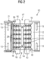
- FIG. 2 shows a corresponding thereto side view of the fuse link in a sectional view.
- the fuse link 10 has a ceramic body 11, which is formed in the present case as a hollow cylinder, wherein the interior of the ceramic body 11 substantially as a receiving space 12 for receiving solidified sand (not shown) is used.
- a contact element 16 is arranged in each case, via which the fuse link 10 is electrically contacted.
- the contact element 16 has a receptacle 17 in the form of a blind hole, via which an electrical connection element can be securely connected, for example via a screw connection, to the fuse-link insert 10.
- the respective contact element 16 is centered relative to the ceramic body 11. Furthermore, the openings of the hollow cylindrical ceramic body 11 are sealed pressure-tight by the two cover plates 18.
- a hollow cylinder and other hollow shapes for the design of the ceramic body 11 for example, hollow cuboid or hollow prisms are used.
- a plurality of fuse elements 13, which connect the two contact elements 16 in an electrically conductive manner, as well as a so-called identification wire, are furthermore provided 15, which also electrically conductively connects the two contact elements 16, arranged.
- the Kennmeldedraht 15 is guided at one end of the fuse link 10 to the outside and holds there held with a spring under mechanical tension indicator 21 - also called indicator - fixed.
- Each of the fusible conductor 13 has over its length a plurality of bottlenecks 20, on the design of the tripping characteristic of the fuse link 10 is selectively influenced.
- an additional body in the form of a bursting body 14 is arranged in the receiving space 12.
- the remaining receiving space 12 is filled with solidified sand, such as quartz sand, whereby the bursting body 14 is held in position.
- solidified sand such as quartz sand
- the bursting body 16 occupies a defined volume in the solidified sand and breaks up when the internal pressure in the interior of the ceramic body 11 exceeds a predefined threshold value, for example due to a temperature expansion of the solidified sand during activation of the fuse link insert 10.
Landscapes
- Engineering & Computer Science (AREA)
- Computer Security & Cryptography (AREA)
- Fuses (AREA)
Applications Claiming Priority (1)
| Application Number | Priority Date | Filing Date | Title |
|---|---|---|---|
| DE102011005883A DE102011005883A1 (de) | 2011-03-22 | 2011-03-22 | Schmelzsicherungseinsatz und Überstrom-Schutzeinrichtung |
Publications (1)
| Publication Number | Publication Date |
|---|---|
| EP2503583A1 true EP2503583A1 (fr) | 2012-09-26 |
Family
ID=45655905
Family Applications (1)
| Application Number | Title | Priority Date | Filing Date |
|---|---|---|---|
| EP12155699A Withdrawn EP2503583A1 (fr) | 2011-03-22 | 2012-02-16 | Cartouche fusible et dispositif de protection contre les surtensions |
Country Status (3)
| Country | Link |
|---|---|
| US (1) | US20120242448A1 (fr) |
| EP (1) | EP2503583A1 (fr) |
| DE (1) | DE102011005883A1 (fr) |
Families Citing this family (1)
| Publication number | Priority date | Publication date | Assignee | Title |
|---|---|---|---|---|
| US9689771B2 (en) | 2013-06-13 | 2017-06-27 | Progressive Products, Inc. | Pipe and conduit wear detection system |
Citations (3)
| Publication number | Priority date | Publication date | Assignee | Title |
|---|---|---|---|---|
| DE1463002A1 (de) * | 1963-07-17 | 1969-04-10 | Continental Elektro Ind Ag | Sicherung,insbesondere Hochleistungs-Sicherung |
| DE2115930A1 (de) * | 1971-03-15 | 1971-10-07 | Bbc Brown Boveri & Cie | Schmelzsicherung |
| FR2266291A1 (en) * | 1974-03-29 | 1975-10-24 | Faeam | Cylindrical cartridge fuse - has inner compartments that shatter to permit gas expansion |
Family Cites Families (11)
| Publication number | Priority date | Publication date | Assignee | Title |
|---|---|---|---|---|
| DE143555C (fr) * | ||||
| DE635490C (de) * | 1931-11-08 | 1936-09-18 | Max Buchholz | Hochleistungsschmelzsicherung fuer Hochspannung |
| US2091424A (en) * | 1933-05-13 | 1937-08-31 | Schweitzer & Conrad Inc | Fuse |
| US2156058A (en) * | 1937-04-10 | 1939-04-25 | Gen Electric | Electric protective device |
| US2636956A (en) * | 1950-10-31 | 1953-04-28 | Deltron Electric Products Inc | Fused electrical connector |
| US4058785A (en) * | 1976-09-22 | 1977-11-15 | General Electric Company | Current limiting fuse |
| US4091353A (en) * | 1977-03-30 | 1978-05-23 | General Electric Company | Current limiting fuse |
| US4511876A (en) * | 1983-02-07 | 1985-04-16 | Mcgraw-Edison Company | Electrical fuse with response indicator |
| NL8501004A (nl) * | 1985-04-04 | 1986-11-03 | Littelfuse Tracor | Smeltveiligheid. |
| DE19506547C2 (de) * | 1994-08-01 | 1997-01-30 | Siemens Ag | Ganzbereichs-Stromrichtersicherung |
| US6538550B1 (en) * | 1999-02-02 | 2003-03-25 | Mcgraw-Edison Company | High amperage current limiting fuse |
-
2011
- 2011-03-22 DE DE102011005883A patent/DE102011005883A1/de not_active Withdrawn
-
2012
- 2012-02-16 EP EP12155699A patent/EP2503583A1/fr not_active Withdrawn
- 2012-03-14 US US13/419,816 patent/US20120242448A1/en not_active Abandoned
Patent Citations (3)
| Publication number | Priority date | Publication date | Assignee | Title |
|---|---|---|---|---|
| DE1463002A1 (de) * | 1963-07-17 | 1969-04-10 | Continental Elektro Ind Ag | Sicherung,insbesondere Hochleistungs-Sicherung |
| DE2115930A1 (de) * | 1971-03-15 | 1971-10-07 | Bbc Brown Boveri & Cie | Schmelzsicherung |
| FR2266291A1 (en) * | 1974-03-29 | 1975-10-24 | Faeam | Cylindrical cartridge fuse - has inner compartments that shatter to permit gas expansion |
Also Published As
| Publication number | Publication date |
|---|---|
| US20120242448A1 (en) | 2012-09-27 |
| DE102011005883A1 (de) | 2012-09-27 |
Similar Documents
| Publication | Publication Date | Title |
|---|---|---|
| EP2025049B1 (fr) | Dispositif de protection contre la surintensite de courant destine a etre utilise dans des appareils de protection contre la surtension avec declencheur mecanique supplementaire, de preference conçu comme percuteur | |
| DE102018213522B4 (de) | Schmelzsicherung, Sicherungskörper, System und Verfahren | |
| DE102011052805B4 (de) | Sicherung | |
| DE102010015814B4 (de) | Überspannungsschutzelement | |
| DE202006020737U1 (de) | Passive oder aktive Kurzschließeinrichtung für den Einsatz in Nieder- und Mittelspannungsanlagen zum Sach- und Personenschutz | |
| DE10134752A1 (de) | Überspannungsableiter | |
| EP3264439B1 (fr) | Élément fusible et dispositif de protection contre les surtensions | |
| AT522585B1 (de) | Vorrichtung zum Trennen der elektrischen Verbindung zu einer Batteriezelle im Ausgasungsfall | |
| DE2350271C3 (fr) | ||
| EP3844792B1 (fr) | Fusible avec fonction de mesure intégrée | |
| EP3867939B1 (fr) | Fusible avec fonction de mesure intégrée | |
| EP2212977B1 (fr) | Parafoudre avec protection thermique contre les surcharges | |
| EP2212976B1 (fr) | Parasurtenseur avec protection thermique contre les surcharges | |
| DE102011005884A1 (de) | Schmelzsicherungseinsatz und Überstrom-Schutzeinrichtung | |
| EP3853878B1 (fr) | Corps de sécurité et fusible | |
| EP2503583A1 (fr) | Cartouche fusible et dispositif de protection contre les surtensions | |
| DE102012021668A1 (de) | Vorrichtung zum Schutz eines mit einem Wechselstrom versorgten elektrischen Stromkreises, die in ein Schütz integrierbar ist | |
| DE102012208755A1 (de) | Schmelzleiter-Anordnung, Schmelzsicherungseinsatz und Überstrom-Schutzeinrichtung | |
| DE19851311B4 (de) | Elektrische Bruchsicherung mit Memory-Einsatz und dafür geeignete Memory-Legierungen | |
| DE202013003505U1 (de) | Thermosensitiver und/oder drucksensitiver Schalter mit Auslöseeinrichtung | |
| EP3447784B1 (fr) | Procédé de fabrication destiné à la fabrication d'un corps de fusible, corps de fusible et coupe-circuit fusible | |
| DE3620973A1 (de) | Oelbad-loeschrohrsicherungspatrone | |
| DE202006020213U1 (de) | Überstromschutzeinrichtung für den Einsatz in Überspannungsschutzgeräten mit zusätzlichem mechanischen Auslöser, bevorzugt als Schlagbolzen ausgeführt | |
| DE102012208760A1 (de) | Schmelzsicherungseinsatz und Überstrom-Schutzeinrichtung | |
| DE102014212068A1 (de) | Schmelzsicherung und Verfahren zur individuellen Einstellung eines Bemessungsstromes einer Schmelzsicherung |
Legal Events
| Date | Code | Title | Description |
|---|---|---|---|
| PUAI | Public reference made under article 153(3) epc to a published international application that has entered the european phase |
Free format text: ORIGINAL CODE: 0009012 |
|
| AK | Designated contracting states |
Kind code of ref document: A1 Designated state(s): AL AT BE BG CH CY CZ DE DK EE ES FI FR GB GR HR HU IE IS IT LI LT LU LV MC MK MT NL NO PL PT RO RS SE SI SK SM TR |
|
| AX | Request for extension of the european patent |
Extension state: BA ME |
|
| 17P | Request for examination filed |
Effective date: 20121210 |
|
| RAP1 | Party data changed (applicant data changed or rights of an application transferred) |
Owner name: SIEMENS AKTIENGESELLSCHAFT |
|
| GRAP | Despatch of communication of intention to grant a patent |
Free format text: ORIGINAL CODE: EPIDOSNIGR1 |
|
| INTG | Intention to grant announced |
Effective date: 20151102 |
|
| STAA | Information on the status of an ep patent application or granted ep patent |
Free format text: STATUS: THE APPLICATION IS DEEMED TO BE WITHDRAWN |
|
| 18D | Application deemed to be withdrawn |
Effective date: 20160315 |