EP2503583A1 - Melt resistant insert and overload protection device - Google Patents
Melt resistant insert and overload protection device Download PDFInfo
- Publication number
- EP2503583A1 EP2503583A1 EP12155699A EP12155699A EP2503583A1 EP 2503583 A1 EP2503583 A1 EP 2503583A1 EP 12155699 A EP12155699 A EP 12155699A EP 12155699 A EP12155699 A EP 12155699A EP 2503583 A1 EP2503583 A1 EP 2503583A1
- Authority
- EP
- European Patent Office
- Prior art keywords
- fuse
- ceramic body
- sand
- insert
- solidified
- Prior art date
- Legal status (The legal status is an assumption and is not a legal conclusion. Google has not performed a legal analysis and makes no representation as to the accuracy of the status listed.)
- Withdrawn
Links
Images

Classifications
-
- H—ELECTRICITY
- H01—ELECTRIC ELEMENTS
- H01H—ELECTRIC SWITCHES; RELAYS; SELECTORS; EMERGENCY PROTECTIVE DEVICES
- H01H85/00—Protective devices in which the current flows through a part of fusible material and this current is interrupted by displacement of the fusible material when this current becomes excessive
- H01H85/0078—Security-related arrangements
- H01H85/0082—Security-related arrangements preventing explosion of the cartridge
-
- H—ELECTRICITY
- H01—ELECTRIC ELEMENTS
- H01H—ELECTRIC SWITCHES; RELAYS; SELECTORS; EMERGENCY PROTECTIVE DEVICES
- H01H85/00—Protective devices in which the current flows through a part of fusible material and this current is interrupted by displacement of the fusible material when this current becomes excessive
- H01H85/02—Details
- H01H85/43—Means for exhausting or absorbing gases liberated by fusing arc, or for ventilating excess pressure generated by heating
-
- H—ELECTRICITY
- H01—ELECTRIC ELEMENTS
- H01H—ELECTRIC SWITCHES; RELAYS; SELECTORS; EMERGENCY PROTECTIVE DEVICES
- H01H85/00—Protective devices in which the current flows through a part of fusible material and this current is interrupted by displacement of the fusible material when this current becomes excessive
- H01H85/02—Details
- H01H85/04—Fuses, i.e. expendable parts of the protective device, e.g. cartridges
- H01H85/05—Component parts thereof
- H01H85/165—Casings
- H01H85/175—Casings characterised by the casing shape or form
-
- H—ELECTRICITY
- H01—ELECTRIC ELEMENTS
- H01H—ELECTRIC SWITCHES; RELAYS; SELECTORS; EMERGENCY PROTECTIVE DEVICES
- H01H85/00—Protective devices in which the current flows through a part of fusible material and this current is interrupted by displacement of the fusible material when this current becomes excessive
- H01H85/02—Details
- H01H85/04—Fuses, i.e. expendable parts of the protective device, e.g. cartridges
- H01H85/05—Component parts thereof
- H01H85/18—Casing fillings, e.g. powder
Definitions
- the invention relates to a fuse insert - especially for semiconductor protection fuses - which has a filled with solidified sand ceramic body. Furthermore, the invention relates to an overcurrent protection device with such a fuse link.
- a fuse is an overcurrent protection device that interrupts the circuit by melting one or more fusible links when the current exceeds a certain level over a certain period of time. It consists of an insulating body, which has two electrical connections, which are interconnected in the interior of the insulating body by a fusible link. The fusible conductor is heated by the current flowing through it and melts when the relevant nominal current of the fuse is clearly exceeded for a certain period of time. Due to its good insulating effect is used as the material for the insulating body mostly ceramic.
- the fusible link is surrounded by quartz sand.
- a ceramic body forms the housing of the fuse link, in which the solidified sand, the electrical connections and the fusible conductor are accommodated or held.
- the quartz sand acts as an arc extinguishing agent: the rated current of the fuse is clearly exceeded - for example, due to a short circuit - so this leads to a response of the fuse, in the course of which the fusible element melts first and then evaporated due to the high temperature development. This creates an electrically conductive plasma, via which the current flow between the electrical connections is initially maintained - it arises an arc.
- the fuse protection insert according to the invention in particular for semiconductor protection fuses, has a ceramic body filled with solidified sand, wherein an additional body is introduced into the solidified sand. This is designed such that upon an increase in an internal pressure in the ceramic body due to a temperature expansion of the solidified sand by the additional body, an additional volume in the ceramic body for expansion of the solidified sand is released.
- the ceramic body and the solidified sand generally have different coefficients of thermal expansion, ie, the solidified sand expands at a temperature increase more than the ceramic body surrounding the solidified sand, which at a temperature increase to an increase of the internal pressure in the ceramic body and thus to stresses in the ceramic body leads.
- the internal pressure arising in the ceramic body can be limited to a tolerable value. In this way, damage to the ceramic body by stress cracks, caused by the different degrees of thermal expansion of the solidified sand and the ceramic body, avoided. The robustness of the fuse insert is thereby significantly improved.
- the ceramic body can be used for the production of the ceramic body to a ceramic with a lower alumina content.
- a ceramic is cheaper to produce and, on the other hand, simpler to process, so that the manufacturing costs of the fuse-linkage insert can be significantly reduced as a result.
- a simpler ceramic can thus be used for the same power; special designs for problematic operating conditions, which even high-quality ceramics are not sufficient for, can be realized by introducing an additional body into the solidified sand.
- the fuse insert of the additional body is designed as a burst body, which breaks when a predefined internal pressure in the ceramic body, whereby the additional volume is released.
- the bursting body introduced into the sand generally has a thin-walled housing which irreversibly yields and breaks at a predefined internal pressure prevailing in the interior of the ceramic body, whereby the volume surrounded by the thin-walled housing is at least partially released and solidified for further expansion Sandes is available.
- a plurality of bursting bodies may be introduced into the solidified sand, which are designed, for example, for different internal pressures and, when the internal pressure swells, break one after the other, so that the additional volume for further expansion of the solidified sand is cascaded, ie. in several portions, is released.
- the bursting body is filled with an air or gas mixture.
- the filling of the bursting body with air represents a simple and cost-effective way to realize the improvement of the fuse link.
- a gas mixture - for example, inert that is, inert gases such as nitrogen or noble gases - can be used.
- the bursting body is filled with unconsolidated sand.
- the additional volume to be provided by breaking the burst body can be limited to a low value without impairing the accuracy of the triggering of the fuse link insert.
- a certain manufacturing accuracy of the bursting body with respect to its geometry and its wall thickness is required; this in turn requires a minimum size of the burst body, which is difficult to implement with only a small additional volume.
- the filling of the bursting body with unconsolidated sand makes it possible to provide only a small additional volume for further expansion of the solidified sand, even with the geometrically determined minimum size of the bursting body described above, wherein the breaking of the bursting body in dependence of the internal pressure with relative good accuracy can be predetermined.
- the bursting body is filled with an elastic material.
- filling with an elastic material is a suitable way to provide only a small additional volume for further expansion of the consolidated sand.
- the filling with elastic material has the further advantage that even after the bursting of the bursting body no voids are formed in the solidified sand. Instead, the further expansion of the solidified Sand at almost constant internal pressure realized by squeezing the elastic body.
- the fuse insert of the additional body is designed as a compressible solid body. Also in this case, the further expansion of the solidified sand is realized at almost constant or only slightly increasing internal pressure by compressing the elastic body. However, this principle does not act only from the threshold value of the internal pressure at which the auxiliary body breaks, but already from the beginning.
- the fuse insert of the ceramic body can be produced by extrusion.
- An extrusion process is a simple and extremely cost-effective way of producing the ceramic body, which is particularly suitable for the processing of simple ceramic materials.
- High quality ceramics, especially those with a high alumina content, are only partially suitable or even completely unsuitable for processing by means of an extrusion process.
- the overcurrent protection device according to the invention has at least one fuse link according to the above explanations.
- advantages of such an overcurrent protection device reference is made to the preceding statements on the advantages of the fuse protection insert according to the invention.
- FIG. 1 the fuse protection insert 10 according to the invention is shown in a perspective view.
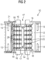
- FIG. 2 shows a corresponding thereto side view of the fuse link in a sectional view.
- the fuse link 10 has a ceramic body 11, which is formed in the present case as a hollow cylinder, wherein the interior of the ceramic body 11 substantially as a receiving space 12 for receiving solidified sand (not shown) is used.
- a contact element 16 is arranged in each case, via which the fuse link 10 is electrically contacted.
- the contact element 16 has a receptacle 17 in the form of a blind hole, via which an electrical connection element can be securely connected, for example via a screw connection, to the fuse-link insert 10.
- the respective contact element 16 is centered relative to the ceramic body 11. Furthermore, the openings of the hollow cylindrical ceramic body 11 are sealed pressure-tight by the two cover plates 18.
- a hollow cylinder and other hollow shapes for the design of the ceramic body 11 for example, hollow cuboid or hollow prisms are used.
- a plurality of fuse elements 13, which connect the two contact elements 16 in an electrically conductive manner, as well as a so-called identification wire, are furthermore provided 15, which also electrically conductively connects the two contact elements 16, arranged.
- the Kennmeldedraht 15 is guided at one end of the fuse link 10 to the outside and holds there held with a spring under mechanical tension indicator 21 - also called indicator - fixed.
- Each of the fusible conductor 13 has over its length a plurality of bottlenecks 20, on the design of the tripping characteristic of the fuse link 10 is selectively influenced.
- an additional body in the form of a bursting body 14 is arranged in the receiving space 12.
- the remaining receiving space 12 is filled with solidified sand, such as quartz sand, whereby the bursting body 14 is held in position.
- solidified sand such as quartz sand
- the bursting body 16 occupies a defined volume in the solidified sand and breaks up when the internal pressure in the interior of the ceramic body 11 exceeds a predefined threshold value, for example due to a temperature expansion of the solidified sand during activation of the fuse link insert 10.
Landscapes
- Engineering & Computer Science (AREA)
- Computer Security & Cryptography (AREA)
- Fuses (AREA)
Abstract
Der erfindungsgemäße Schmelzsicherungseinsatz (10), insbesondere für Halbleiter-Schutz-Sicherungen, weist einen mit verfestigtem Sand gefüllten Keramikkörper (11) auf, wobei in den verfestigten Sand ein Zusatzkörper (14) eingebracht ist. Dieser ist derart ausgebildet, dass bei einer Erhöhung eines Innendrucks in dem Keramikkörper (11) aufgrund einer Temperaturausdehnung des verfestigten Sandes durch den Zusatzkörper (14) ein zusätzliches Volumen in dem Keramikkörper (11) zur Ausdehnung des verfestigten Sandes freigesetzt wird. Beschädigung des Keramikkörpers (11) durch Spannungsrisse, hervorgerufen durch die unterschiedlich starke Temperaturausdehnung des verfestigten Sandes und des Keramikkörpers (11) infolge einer Temperaturerhöhung und dem damit verbundenen Anstieg des Innendrucks in dem Keramikkörper (11), können hierdurch vermieden bzw. begrenzt werden. Die Robustheit des Schmelzsicherungseinsatzes (10) wird dadurch deutlich verbessert.The fuse insert (10) according to the invention, in particular for semiconductor protection fuses, has a ceramic body (11) filled with solidified sand, an additional body (14) being introduced into the solidified sand. This is designed such that when the internal pressure in the ceramic body (11) increases due to temperature expansion of the solidified sand through the additional body (14), an additional volume is released in the ceramic body (11) for expansion of the solidified sand. Damage to the ceramic body (11) due to stress cracks caused by the different degrees of thermal expansion of the solidified sand and the ceramic body (11) as a result of an increase in temperature and the associated increase in the internal pressure in the ceramic body (11) can be avoided or limited. The robustness of the fuse insert (10) is thereby significantly improved.
Description
Die Erfindung betrifft einen Schmelzsicherungseinsatz - insbesondere für Halbleiter-Schutz-Sicherungen - welcher einen mit verfestigtem Sand gefüllten Keramikkörper aufweist. Ferner betrifft die Erfindung eine Überstrom-Schutzeinrichtung mit einem derartigen Schmelzsicherungseinsatz.The invention relates to a fuse insert - especially for semiconductor protection fuses - which has a filled with solidified sand ceramic body. Furthermore, the invention relates to an overcurrent protection device with such a fuse link.
Eine Schmelzsicherung ist eine Überstromschutzeinrichtung, die durch das Abschmelzen eines oder mehrerer Schmelzleiter den Stromkreis unterbricht, wenn die Stromstärke einen bestimmten Wert über eine bestimmte Zeitdauer hinweg überschreitet. Sie besteht aus einem isolierenden Körper, welcher zwei elektrische Anschlüsse aufweist, die im Inneren des isolierenden Körpers durch einen Schmelzleiter miteinander verbunden sind. Der Schmelzleiter wird durch den ihn durchfließenden Strom erwärmt und schmilzt, wenn der maßgebliche Nennstrom der Sicherung für eine bestimmte Zeit deutlich überschritten wird. Aufgrund seiner guten Isolationswirkung wird als Material für den isolierenden Körper zumeist Keramik verwendet.A fuse is an overcurrent protection device that interrupts the circuit by melting one or more fusible links when the current exceeds a certain level over a certain period of time. It consists of an insulating body, which has two electrical connections, which are interconnected in the interior of the insulating body by a fusible link. The fusible conductor is heated by the current flowing through it and melts when the relevant nominal current of the fuse is clearly exceeded for a certain period of time. Due to its good insulating effect is used as the material for the insulating body mostly ceramic.
Bei einem Sand verfestigten Schmelzsicherungseinsatz ist der Schmelzleiter von Quarzsand umgeben. Ein Keramikkörper bildet das Gehäuse des Sicherungseinsatzes, in dem der verfestigte Sand, die elektrischen Anschlüsse sowie der Schmelzleiter aufgenommen bzw. gehaltert sind. Der Quarzsand fungiert dabei als Lichtbogenlöschmittel: wird der Nennstrom der Schmelzsicherung deutlich überschrittenen - beispielsweise aufgrund eines Kurzschlusses - so führt dies zu einem Ansprechen der Schmelzsicherung, in dessen Verlauf der Schmelzleiter zunächst schmilzt und anschließend aufgrund der hohen Temperaturentwicklung verdampft. Dabei entsteht ein elektrisch leitendes Plasma, über das der Stromfluss zwischen den elektrischen Anschlüssen zunächst aufrecht erhalten wird - es entsteht ein Lichtbogen. Indem sich der Metalldampf des verdampften Schmelzleiters auf der Oberfläche der Quarzsand-Körner niederschlägt, wird der Lichtbogen wiederum abgekühlt. In der Folge steigt der Widerstand im Inneren des Sicherungseinsatzes derart an, dass der Lichtbogen endgültig verlischt. Die durch die Schmelzsicherung zu schützende Leitung ist damit unterbrochen.In a sand-solidified fuselage insert, the fusible link is surrounded by quartz sand. A ceramic body forms the housing of the fuse link, in which the solidified sand, the electrical connections and the fusible conductor are accommodated or held. The quartz sand acts as an arc extinguishing agent: the rated current of the fuse is clearly exceeded - for example, due to a short circuit - so this leads to a response of the fuse, in the course of which the fusible element melts first and then evaporated due to the high temperature development. This creates an electrically conductive plasma, via which the current flow between the electrical connections is initially maintained - it arises an arc. As the metal vapor of the vaporized fusible conductor precipitates on the surface of the silica sand grains, the arc is again cooled. As a result, the resistance in the interior of the fuse link increases in such a way that the arc finally disappears. The line to be protected by the fuse is thus interrupted.
Bei Sand verfestigten Schmelzsicherungseinsätzen mit großem Sandvolumen kommt es aufgrund der unterschiedlichen Temperaturausdehnungskoeffizienten des Quarzsandes einerseits und des Keramikkörpers andererseits zu Spannungen im Keramikkörper, welche letztendlich bis zum Bruch des Keramikkörpers führen können. Am Markt erhältliche Schmelzsicherungseinsätze begegnen dieser Problematik mit dem Einsatz spezieller, hochwertiger Keramiken, welche sich beispielsweise durch einen höheren Aluminiumoxidgehalt auszeichnen. Derartige Keramiken weisen neben einer höheren Festigkeit auch noch einen größeren Temperaturausdehnungskoeffizienten auf als vergleichbare Keramiken mit einem geringeren Aluminiumoxidgehalt. Beide Eigenschaften - die höhere Festigkeit und der höhere Temperaturausdehnungskoeffizient - wirken dem Problem einer Beschädigung des Keramikkörpers entgegen. Jedoch sind die hierfür in Frage kommenden Keramikwerkstoffe aufgrund ihrer besonderen Qualitätseigenschaften relativ teuer.For sand-solidified fusible link inserts with large volumes of sand, due to the different thermal expansion coefficients of the quartz sand on the one hand and the ceramic body on the other hand to tensions in the ceramic body, which can ultimately lead to breakage of the ceramic body. Available on the market fuse inserts meet this problem with the use of special, high-quality ceramics, which are characterized for example by a higher alumina content. Such ceramics have not only a higher strength but also a larger coefficient of thermal expansion than comparable ceramics with a lower alumina content. Both properties - the higher strength and the higher coefficient of thermal expansion - counteract the problem of damage to the ceramic body. However, the ceramic materials in question are relatively expensive due to their special quality properties.
Zur Reduzierung der Spannungen im Keramikkörper aufgrund der Temperaturausdehnung des verfestigten Sandes werden ferner Schmelzsicherungseinsätze angeboten, bei denen entlang des Inneren Umfangs des Keramikkörpers ein dämpfendes Element zwischen dem Keramikkörper und dem verfestigten Sand angeordnet ist. Diese Anordnung hat jedoch den Nachteil, dass die Wärmeabfuhr des Schmelzsicherungseinsatzes und damit das Auslöse- und Abschaltverhalten des Schmelzsicherungseinsatzes deutlich verschlechtert werden.To reduce the stresses in the ceramic body due to the temperature expansion of the solidified sand fusible inserts are further provided in which along the inner circumference of the ceramic body, a damping element between the ceramic body and the solidified sand is arranged. However, this arrangement has the disadvantage that the heat dissipation of the fuse link and thus the tripping and shutdown of the fuse link are significantly deteriorated.
Es ist deshalb die Aufgabe der vorliegenden Erfindung einen Schmelzsicherungseinsatz sowie eine Überstrom-Schutzeinrichtung mit einem derartigen Schmelzsicherungseinsatz bereitzustellen, welche sich durch eine verbesserte Robustheit bei gleichzeitig einfacher und kostengünstiger Herstellbarkeit auszeichnen.It is therefore an object of the present invention to provide a fuse link as well as an overcurrent protection device with such a fuse link insert, which are characterized by improved robustness and at the same time simple and cost-effective manufacturability.
Diese Aufgabe wird durch den Schmelzsicherungseinsatz sowie die Überstrom-Schutzeinrichtung gemäß den unabhängigen Ansprüchen gelöst. Vorteilhafte Ausgestaltungen sind Gegenstand der abhängigen Ansprüche.This object is achieved by the fuse link as well as the overcurrent protection device according to the independent claims. Advantageous embodiments are the subject of the dependent claims.
Der erfindungsgemäße Schmelzsicherungseinsatz, insbesondere für Halbleiter-Schutz-Sicherungen, weist einen mit verfestigtem Sand gefüllten Keramikkörper auf, wobei in den verfestigten Sand ein Zusatzkörper eingebracht ist. Dieser ist derart ausgebildet, dass bei einer Erhöhung eines Innendrucks in dem Keramikkörper aufgrund einer Temperaturausdehnung des verfestigten Sandes durch den Zusatzkörper ein zusätzliches Volumen in dem Keramikkörper zur Ausdehnung des verfestigten Sandes freigesetzt wird.The fuse protection insert according to the invention, in particular for semiconductor protection fuses, has a ceramic body filled with solidified sand, wherein an additional body is introduced into the solidified sand. This is designed such that upon an increase in an internal pressure in the ceramic body due to a temperature expansion of the solidified sand by the additional body, an additional volume in the ceramic body for expansion of the solidified sand is released.
Der Keramikkörper und der verfestigte Sand weisen in der Regel unterschiedliche Temperaturausdehnungskoeffizienten auf, d.h. der verfestigte Sand dehnt sich bei einer Temperaturerhöhung stärker aus als der den verfestigten Sand umgebende Keramikkörper, was bei einer Temperaturerhöhung zu einer Erhöhung des Innendrucks im Keramikkörper und damit zu Spannungen im Keramikkörper führt. Durch die Verwendung eines Zusatzkörpers, mit dessen Hilfe bei einer Erhöhung des Innendrucks ein zusätzliches Volumen in dem Keramikkörper bereitgestellt wird, welches zur weiteren Ausdehnung des verfestigten Sandes zur Verfügung steht, kann der in dem Keramikköper entstehende Innendruck auf einen tolerierbaren Wert begrenzt werden. Auf diese Weise wird eine Beschädigung des Keramikkörpers durch Spannungsrisse, hervorgerufen durch die unterschiedlich starke Temperaturausdehnung des verfestigten Sandes und des Keramikkörpers, vermieden. Die Robustheit des Schmelzsicherungseinsatzes wird dadurch deutlich verbessert.The ceramic body and the solidified sand generally have different coefficients of thermal expansion, ie, the solidified sand expands at a temperature increase more than the ceramic body surrounding the solidified sand, which at a temperature increase to an increase of the internal pressure in the ceramic body and thus to stresses in the ceramic body leads. By using an additional body, with the help of an increase in the internal pressure is provided an additional volume in the ceramic body, which is available for further expansion of the solidified sand, the internal pressure arising in the ceramic body can be limited to a tolerable value. In this way, damage to the ceramic body by stress cracks, caused by the different degrees of thermal expansion of the solidified sand and the ceramic body, avoided. The robustness of the fuse insert is thereby significantly improved.
Weiterhin kann zur Herstellung des Keramikkörpers auf eine Keramik mit einem geringeren Aluminiumoxidgehalt zurückgegriffen werden. Eine derartige Keramik ist einerseits preiswerter in der Herstellung und andererseits einfacher in der Verarbeitung, so dass hierdurch auch die Herstellkosten des Schmelzsicherungseinsatzes deutlich reduziert werden können. Bei Bauformen für den Standardeinsatz kann somit bei gleicher Leistung eine einfachere Keramik verwendet werden; spezielle Bauformen für problematische Einsatzbedingungen, denen selbst hochwertige Keramiken nicht genügen, können durch Einbringen eines Zusatzkörpers in den verfestigten Sand realisiert werden.Furthermore, can be used for the production of the ceramic body to a ceramic with a lower alumina content. On the one hand, such a ceramic is cheaper to produce and, on the other hand, simpler to process, so that the manufacturing costs of the fuse-linkage insert can be significantly reduced as a result. With designs for standard use, a simpler ceramic can thus be used for the same power; special designs for problematic operating conditions, which even high-quality ceramics are not sufficient for, can be realized by introducing an additional body into the solidified sand.
In einer vorteilhaften Weiterbildung des Schmelzsicherungseinsatzes ist der Zusatzkörper als Berstkörper ausgebildet, welcher bei Erreichen eines vordefinierten Innendrucks in dem Keramikkörper zerbricht, wodurch das zusätzliche Volumen freigesetzt wird. Der in den Sand eingebrachte Berstkörper weist in der Regel ein dünnwandiges Gehäuse auf, welches bei einem vordefinierten, im Inneren des Keramikkörpers herrschenden Innendruck irreversibel nachgibt und zerbricht, wodurch das von dem dünnwandigen Gehäuse umgebene Volumen zumindest teilweise freigesetzt wird und für eine weitere Ausdehnung des verfestigten Sandes zur Verfügung steht. Dabei können in den verfestigten Sand auch mehrere Berstkörper eingebracht sein, welche beispielsweise für verschiedene Innendrücke ausgelegt sind und bei einem Anschwellen des Innendrucks nacheinander zerbrechen, so dass das zusätzliche Volumen zur weiteren Ausdehnung des verfestigten Sandes kaskadenartig, d.h. in mehreren Portionen, freigegeben wird.In an advantageous development of the fuse insert of the additional body is designed as a burst body, which breaks when a predefined internal pressure in the ceramic body, whereby the additional volume is released. The bursting body introduced into the sand generally has a thin-walled housing which irreversibly yields and breaks at a predefined internal pressure prevailing in the interior of the ceramic body, whereby the volume surrounded by the thin-walled housing is at least partially released and solidified for further expansion Sandes is available. In this case, a plurality of bursting bodies may be introduced into the solidified sand, which are designed, for example, for different internal pressures and, when the internal pressure swells, break one after the other, so that the additional volume for further expansion of the solidified sand is cascaded, ie. in several portions, is released.
In einer weiteren vorteilhaften Weiterbildung des Schmelzsicherungseinsatzes ist der Berstkörper mit einem Luft oder Gasgemisch gefüllt. Die Füllung des Berstkörpers mit Luft stellt eine einfach und kostengünstig zu realisierende Möglichkeit zur Verbesserung des Schmelzsicherungseinsatzes dar. Anstelle von Luft kann auch ein Gasgemisch - beispielsweise inerte, das heißt reaktionsträge Gase wie Stickstoff oder Edelgase - verwendet werden.In a further advantageous development of the fuse insert the bursting body is filled with an air or gas mixture. The filling of the bursting body with air represents a simple and cost-effective way to realize the improvement of the fuse link. Instead of air, a gas mixture - for example, inert, that is, inert gases such as nitrogen or noble gases - can be used.
In einer weiteren vorteilhaften Weiterbildung des Schmelzsicherungseinsatzes ist der Berstkörper mit unverfestigtem Sand gefüllt. Auf diese Weise kann das zusätzliche, durch Zerbrechen des Berstkörpers bereitzustellende Volumen auf einen geringen Wert limitiert werden, ohne dass dabei die Genauigkeit der Auslösung des Schmelzsicherungseinsatzes beeinträchtigt wird. Um diese Genauigkeit einzuhalten, d.h. um den Schwellwert des Innendrucks, ab dem der Berstkörper zerbrechen soll, möglichst genau zu bestimmen, ist eine bestimmte Herstellungsgenauigkeit des Berstkörpers hinsichtlich seiner Geometrie sowie seiner Wandstärke erforderlich; dies wiederum erfordert eine Mindestgröße des Berstkörpers, die bei nur geringem zusätzlichen Volumen schwer zu realisieren ist. Die Füllung des Berstkörpers mit unverfestigtem Sand hingegen erlaubt es, auch bei der oben beschriebenen, geometrisch bedingten Mindestgröße des Berstkörpers, nur ein geringes zusätzliches Volumen zur weiteren Ausdehnung des verfestigten Sandes zur Verfügung zu stellen, wobei das Zerbrechen des Berstkörpers in Abhängigkeit des Innendrucks mit relativ guter Genauigkeit vorherbestimmt werden kann.In a further advantageous development of the fuse insert the bursting body is filled with unconsolidated sand. In this way, the additional volume to be provided by breaking the burst body can be limited to a low value without impairing the accuracy of the triggering of the fuse link insert. To maintain this accuracy, i. In order to determine the threshold value of the internal pressure, from which the bursting body should break, as accurately as possible, a certain manufacturing accuracy of the bursting body with respect to its geometry and its wall thickness is required; this in turn requires a minimum size of the burst body, which is difficult to implement with only a small additional volume. The filling of the bursting body with unconsolidated sand, however, makes it possible to provide only a small additional volume for further expansion of the solidified sand, even with the geometrically determined minimum size of the bursting body described above, wherein the breaking of the bursting body in dependence of the internal pressure with relative good accuracy can be predetermined.
In einer weiteren vorteilhaften Weiterbildung des Schmelzsicherungseinsatzes ist der Berstkörper mit einem elastischen Material gefüllt. Wie auch die Füllung mit unverfestigtem Sand stellt die Füllung mit einem elastischen Material eine geeignete Möglichkeit dar, um nur ein geringes zusätzliches Volumen zur weiteren Ausdehnung des verfestigten Sandes zur Verfügung zu stellen. Die Füllung mit elastischem Material hat dabei den weiteren Vorteil, dass auch nach dem Zerbrechen des Berstkörpers keine Hohlräume in dem verfestigten Sand entstehen. Stattdessen wird die weitere Ausdehnung des verfestigten Sandes bei nahezu gleichbleibendem Innendruck durch ein Zusammendrücken des elastischen Körpers realisiert.In a further advantageous development of the fuse insert the bursting body is filled with an elastic material. Like filling with unconsolidated sand, filling with an elastic material is a suitable way to provide only a small additional volume for further expansion of the consolidated sand. The filling with elastic material has the further advantage that even after the bursting of the bursting body no voids are formed in the solidified sand. Instead, the further expansion of the solidified Sand at almost constant internal pressure realized by squeezing the elastic body.
In einer weiteren vorteilhaften Weiterbildung des Schmelzsicherungseinsatzes ist der Zusatzkörper als komprimierbarer Vollkörper ausgebildet. Auch in diesem Fall wird die weitere Ausdehnung des verfestigten Sandes bei nahezu gleichbleibendem oder nur gering ansteigendem Innendruck durch ein Zusammendrücken des elastischen Körpers realisiert. Dieses Prinzip wirkt dabei jedoch nicht erst ab dem Schwellwert des Innendrucks, bei dem der Zusatzkörper zerbricht, sondern bereits von Anfang an.In a further advantageous development of the fuse insert of the additional body is designed as a compressible solid body. Also in this case, the further expansion of the solidified sand is realized at almost constant or only slightly increasing internal pressure by compressing the elastic body. However, this principle does not act only from the threshold value of the internal pressure at which the auxiliary body breaks, but already from the beginning.
In einer weiteren vorteilhaften Weiterbildung des Schmelzsicherungseinsatzes ist der Keramikkörper durch Extrusion herstellbar. Ein Extrusionsverfahren stellt eine einfache und überaus kostengünstige Möglichkeit zur Herstellung des Keramikkörpers dar, welche insbesondere für die Verarbeitung einfacher Keramikwerkstoffe geeignet ist. Hochwertige Keramikwerkstoffe, insbesondere solche mit einem hohen Aluminiumoxidgehalt, sind zur Verarbeitung mit Hilfe eines Extrusionsverfahrens nur bedingt geeignet oder sogar gänzlich ungeeignet.In a further advantageous development of the fuse insert of the ceramic body can be produced by extrusion. An extrusion process is a simple and extremely cost-effective way of producing the ceramic body, which is particularly suitable for the processing of simple ceramic materials. High quality ceramics, especially those with a high alumina content, are only partially suitable or even completely unsuitable for processing by means of an extrusion process.
Die erfindungsgemäße Überstrom-Schutzeinrichtung weist zumindest einen Schmelzsicherungseinsatz gemäß den obigen Ausführungen auf. Hinsichtlich der Vorteile einer derartigen Überstrom-Schutzeinrichtung wird auf die vorangestellten Ausführungen zu den Vorteilen des erfindungsgemäßen Schmelzsicherungseinsatzes verwiesen.The overcurrent protection device according to the invention has at least one fuse link according to the above explanations. With regard to the advantages of such an overcurrent protection device, reference is made to the preceding statements on the advantages of the fuse protection insert according to the invention.
Im Folgenden wird ein Ausführungsbeispiel des erfindungsgemäßen Schmelzsicherungseinsatzes unter Bezug auf die beigefügten Figuren näher erläutert. In den Figuren sind:
- Figur 1
- eine schematische Darstellung des Schmelzsicherungseinsatzes in perspektivischer Ansicht,
- Figur 2
- eine schematische Schnittdarstellung des Schmelzsicherungseinsatzes in einer Seitenansicht.
- FIG. 1
- a schematic representation of the fuse insert in a perspective view,
- FIG. 2
- a schematic sectional view of the fuse insert in a side view.
In den Figuren der Zeichnung sind gleiche Teile stets mit dem gleichen Bezugszeichen versehen. Die Beschreibung gilt für alle Zeichnungsfiguren, in denen das entsprechende Teil ebenfalls zu erkennen ist.In the figures of the drawing, like parts are always provided with the same reference numerals. The description applies to all drawing figures in which the corresponding part can also be recognized.
In
In dem Aufnahmeraum 12 sind weiterhin mehrere Schmelzleiter 13, welche die beiden Kontaktelemente 16 elektrisch leitend miteinander verbinden, sowie ein sogenannter Kennmeldedraht 15, welcher ebenfalls die beiden Kontaktelemente 16 elektrisch leitend verbindet, angeordnet. Der Kennmeldedraht 15 ist an einem Ende des Schmelzsicherungseinsatzes 10 nach außen geführt und hält dort einen mit einer Feder unter mechanischer Spannung gehaltenen Kennmelder 21 - auch Anzeiger genannt - fest. Jeder der Schmelzleiter 13 weist über seine Länge mehrere Engstellen 20 auf, über deren Gestaltung die Auslösecharakteristik des Schmelzsicherungseinsatzes 10 gezielt beeinflussbar ist. Ferner ist in dem Aufnahmeraum 12 ein Zusatzkörper in Form eines Berstkörpers 14 angeordnet. Der verbleibende Aufnahmeraum 12 wird mit verfestigtem Sand, beispielsweise Quarzsand, verfüllt, wodurch auch der Berstkörper 14 in seiner Position gehalten wird. Aus Gründen der Übersichtlichkeit ist der verfestigte Sand in den Figuren jedoch nicht dargestellt. Der Berstkörper 16 nimmt in dem verfestigten Sand ein definiertes Volumen ein und zerbricht, wenn der Innendruck im Inneren des Keramikkörpers 11 - beispielsweise aufgrund einer Temperaturausdehnung des verfestigten Sandes während einer Auslösung des Schmelzsicherungseinsatzes 10 - einen vordefinierten Schwellwert übersteigt.In the receiving
Bei Strömen, die kleiner sind als der Nennstrom des Schmelzsicherungseinsatzes 10, wird in den Schmelzleitern 13 nur soviel Verlustleistung umgesetzt, dass diese in Form von Wärme schnell über den Sand, den Keramikkörper 11 und die Kontaktelemente 16 nach außen abgegeben werden kann. Die Temperatur der Schmelzleiter 13 steigt dabei nicht über deren Schmelzpunkt hinaus an. Fließt jedoch ein Strom, der im Überlastbereich des Schmelzsicherungseinsatzes 10 liegt, so steigt die Temperatur im Inneren des Schmelzsicherungseinsatzes 10 stetig weiter an, bis der Schmelzpunkt der Schmelzleiter 13 überschritten ist und diese an ihren Engstellen 20 durchschmelzen. Bei hohen Fehlerströmen, beispielsweise aufgrund eines Kurzschlusses, wird soviel Energie in den Schmelzleitern 13 umgesetzt, dass diese praktisch auf ihrer ganzen Länge aufgeheizt werden und infolge dessen an allen Engstellen 8 gleichzeitig schmelzen. Da flüssiges Metall noch gute elektrisch leitende Eigenschaften aufweist, fließt der Strom weiterhin durch die Schmelze, bis diese verdampft und ein Lichtbogen entsteht. Durch die dabei auftretenden extrem hohen Temperaturen wird der umgebende Quarzsand aufgeschmolzen, was zu einer chemischen Reaktion des geschmolzenen Metalls mit dem Quarzsand führt. Das hieraus entstehende Reaktionsprodukt ist ein guter Isolator, welcher den Stromfluss schließlich zum Erliegen bringt. Fast zeitgleich mit dem Abschmelzen des Schmelzleiters 13 brennt auch der Kennmeldedraht 15 durch. Infolge dessen wird der Kennmelder 21 nicht mehr festgehalten und aufgrund der anliegenden Federkraft in eine neue Lage bewegt. Auf diese Weise wird das Auslösen des Schmelzsicherungseinsatzes 10 angezeigt.At currents which are smaller than the rated current of the
Durch die Entstehung mehrerer Lichtbögen während der Auslösung des Schmelzsicherungseinsatzes 10 wird viel Wärme erzeugt, was zu einem Temperaturanstieg des verfestigten Sandes und infolgedessen - aufgrund der Wärmedehnung - zu einer Ausdehnung des verfestigten Sandes führt. Da der Temperaturausdehnungskoeffizient des verfestigten Sandes größer ist als der Temperaturausdehnungskoeffizient des den verfestigen Sand umgebenden Keramikkörpers 11, steigt hierdurch der Innendruck in dem Keramikkörpers 11 an. Um Beschädigungen an dem Keramikkörper 11 - beispielsweise Spannungsrisse - zu vermeiden, zerbricht ab einem definierten Schwellwert des Innendrucks der Berstkörper 14. Hierdurch wird das von dem Berstkörper eingeschlossene Volumen - welches beispielsweise mit einem Luft- oder Gasgemisch, mit unverfestigtem Sand oder mit einem elastischen Material gefüllt sein kann - freigegeben. Da sich der verfestigte Sand nun in dieses Volumen hinein ausdehnen kann, sinkt der Innendruck wieder auf einen Wert unterhalb des Schwellwertes ab. Bei richtiger Wahl des Schwellwertes kann somit eine Beschädigung des Keramikkörpers vermieden werden.By the formation of multiple arcs during the release of the
- 1010
- SchmelzsicherungseinsatzFusible link
- 1111
- Keramikkörperceramic body
- 1212
- Aufnahmeraumaccommodation space
- 1313
- Schmelzleiterfuse element
- 1414
- Zusatzkörper / BerstkörperAdditional body / bursting body
- 1515
- KennmeldedrahtCharacteristic signaling wire
- 1616
- Kontaktelementcontact element
- 1717
- Aufnahmeadmission
- 1818
- Abdeckplattecover
- 1919
- Bohrungdrilling
- 2020
- Engstellenbottlenecks
- 2121
- KennmelderFuses, indicator
Claims (8)
dadurch gekennzeichnet,
dass in den verfestigten Sand ein Zusatzkörper (14) eingebracht ist, welcher derart ausgebildet ist, dass bei einer Erhöhung eines Innendrucks in dem Keramikkörper (11) aufgrund einer Temperaturausdehnung des verfestigten Sandes durch den Zusatzkörper (14) ein zusätzliches Volumen in dem Keramikkörper (11) zur Ausdehnung des verfestigten Sandes freigesetzt wird.Fusible link insert (10), in particular for semiconductor protective fuses, having a solidified ceramic body (11),
characterized,
in that an additional body (14) is introduced into the solidified sand, which is designed such that an increase in an internal pressure in the ceramic body (11) due to a temperature expansion of the solidified sand by the additional body (14), an additional volume in the ceramic body (11 ) is released to expand the consolidated sand.
dadurch gekennzeichnet,
dass der Zusatzkörper als Berstkörper (14) ausgebildet ist, welcher bei Erreichen eines vordefinierten Innendrucks in dem Keramikkörper (11) zerbricht, wodurch das zusätzliche Volumen freigesetzt wird.Fuse-fuse insert (10) according to claim 1
characterized,
that the additional body is designed as a bursting body (14) which breaks when a predefined internal pressure in the ceramic body (11) is reached, whereby the additional volume is released.
dadurch gekennzeichnet,
dass der Berstkörper (14) mit einem Luft oder Gasgemisch gefüllt ist.A fusible link insert (10) according to claim 2,
characterized,
that the bursting body (14) is filled with an air or gas mixture.
dadurch gekennzeichnet,
dass der Berstkörper (14) mit unverfestigtem Sand gefüllt ist.A fusible link insert (10) according to claim 2,
characterized,
that the bursting body (14) is filled with unconsolidated sand.
dadurch gekennzeichnet,
dass der Berstkörper (14) mit einem elastischen Material gefüllt ist.A fusible link insert (10) according to claim 2,
characterized,
that the bursting body (14) is filled with an elastic material.
dadurch gekennzeichnet,
dass der Zusatzkörper (14) als komprimierbarer Vollkörper ausgebildet ist.Fuse-fuse insert (10) according to claim 1
characterized,
that the additional body (14) is designed as a compressible solid body.
dadurch gekennzeichnet,
dass der Keramikkörper (11) durch Extrusion herstellbar ist.Fuse-fuse insert (10) according to one of the preceding claims,
characterized,
that the ceramic body (11) is produced by extrusion.
Applications Claiming Priority (1)
| Application Number | Priority Date | Filing Date | Title |
|---|---|---|---|
| DE102011005883A DE102011005883A1 (en) | 2011-03-22 | 2011-03-22 | Fuse-fuse insert and overcurrent protection device |
Publications (1)
| Publication Number | Publication Date |
|---|---|
| EP2503583A1 true EP2503583A1 (en) | 2012-09-26 |
Family
ID=45655905
Family Applications (1)
| Application Number | Title | Priority Date | Filing Date |
|---|---|---|---|
| EP12155699A Withdrawn EP2503583A1 (en) | 2011-03-22 | 2012-02-16 | Melt resistant insert and overload protection device |
Country Status (3)
| Country | Link |
|---|---|
| US (1) | US20120242448A1 (en) |
| EP (1) | EP2503583A1 (en) |
| DE (1) | DE102011005883A1 (en) |
Families Citing this family (1)
| Publication number | Priority date | Publication date | Assignee | Title |
|---|---|---|---|---|
| US9689771B2 (en) | 2013-06-13 | 2017-06-27 | Progressive Products, Inc. | Pipe and conduit wear detection system |
Citations (3)
| Publication number | Priority date | Publication date | Assignee | Title |
|---|---|---|---|---|
| DE1463002A1 (en) * | 1963-07-17 | 1969-04-10 | Continental Elektro Ind Ag | Backup, especially high-performance backup |
| DE2115930A1 (en) * | 1971-03-15 | 1971-10-07 | Bbc Brown Boveri & Cie | Fuse |
| FR2266291A1 (en) * | 1974-03-29 | 1975-10-24 | Faeam | Cylindrical cartridge fuse - has inner compartments that shatter to permit gas expansion |
Family Cites Families (11)
| Publication number | Priority date | Publication date | Assignee | Title |
|---|---|---|---|---|
| DE143555C (en) * | ||||
| DE635490C (en) * | 1931-11-08 | 1936-09-18 | Max Buchholz | High performance fuse for high voltage |
| US2091424A (en) * | 1933-05-13 | 1937-08-31 | Schweitzer & Conrad Inc | Fuse |
| US2156058A (en) * | 1937-04-10 | 1939-04-25 | Gen Electric | Electric protective device |
| US2636956A (en) * | 1950-10-31 | 1953-04-28 | Deltron Electric Products Inc | Fused electrical connector |
| US4058785A (en) * | 1976-09-22 | 1977-11-15 | General Electric Company | Current limiting fuse |
| US4091353A (en) * | 1977-03-30 | 1978-05-23 | General Electric Company | Current limiting fuse |
| US4511876A (en) * | 1983-02-07 | 1985-04-16 | Mcgraw-Edison Company | Electrical fuse with response indicator |
| NL8501004A (en) * | 1985-04-04 | 1986-11-03 | Littelfuse Tracor | MELT SAFETY. |
| DE19506547C2 (en) * | 1994-08-01 | 1997-01-30 | Siemens Ag | Full-range converter fuse |
| US6538550B1 (en) * | 1999-02-02 | 2003-03-25 | Mcgraw-Edison Company | High amperage current limiting fuse |
-
2011
- 2011-03-22 DE DE102011005883A patent/DE102011005883A1/en not_active Withdrawn
-
2012
- 2012-02-16 EP EP12155699A patent/EP2503583A1/en not_active Withdrawn
- 2012-03-14 US US13/419,816 patent/US20120242448A1/en not_active Abandoned
Patent Citations (3)
| Publication number | Priority date | Publication date | Assignee | Title |
|---|---|---|---|---|
| DE1463002A1 (en) * | 1963-07-17 | 1969-04-10 | Continental Elektro Ind Ag | Backup, especially high-performance backup |
| DE2115930A1 (en) * | 1971-03-15 | 1971-10-07 | Bbc Brown Boveri & Cie | Fuse |
| FR2266291A1 (en) * | 1974-03-29 | 1975-10-24 | Faeam | Cylindrical cartridge fuse - has inner compartments that shatter to permit gas expansion |
Also Published As
| Publication number | Publication date |
|---|---|
| US20120242448A1 (en) | 2012-09-27 |
| DE102011005883A1 (en) | 2012-09-27 |
Similar Documents
| Publication | Publication Date | Title |
|---|---|---|
| EP2025049B1 (en) | Over-current protection device with additional mechanical trip, preferably implemented as a trip bolt, for use in over-voltage protection devices | |
| DE102018213522B4 (en) | Fusible link, fuse body, system and method | |
| DE102011052805B4 (en) | fuse | |
| DE102010015814B4 (en) | Snubber | |
| DE202006020737U1 (en) | Passive or active short-circuiting device for use in low and medium voltage systems for property and personal protection | |
| DE10134752A1 (en) | Surge arresters | |
| EP3264439B1 (en) | Fuse link and overload protection device | |
| AT522585B1 (en) | Device for separating the electrical connection to a battery cell in the event of outgassing | |
| DE2350271C3 (en) | ||
| EP3844792B1 (en) | Fuse having an integrated measuring function | |
| EP3867939B1 (en) | Fuse having an integrated measuring function | |
| EP2212977B1 (en) | Overvoltage arrester having thermal overload protection | |
| EP2212976B1 (en) | Surge arrester having thermal overload protection | |
| DE102011005884A1 (en) | Fuse-fuse insert and overcurrent protection device | |
| EP3853878B1 (en) | Fuse element and fuse | |
| EP2503583A1 (en) | Melt resistant insert and overload protection device | |
| DE102012021668A1 (en) | Device for protecting an AC supplied with an alternating current, which can be integrated in a contactor | |
| DE102012208755A1 (en) | Fusible conductor arrangement for fuse insert of overcurrent protection device, has strip-shaped fusible conductors that are arranged rotationally around central axis of cylindrical housing wall of fuse insert | |
| DE19851311B4 (en) | Electrical break protection with memory insert and suitable memory alloys | |
| DE202013003505U1 (en) | Thermosensitive and / or pressure-sensitive switch with triggering device | |
| EP3447784B1 (en) | Fuse, fuse body, and fabrication method for the production of a fuse body | |
| DE3620973A1 (en) | OIL BATH TUBE LOCKING CARTRIDGE | |
| DE202006020213U1 (en) | Overcurrent protection device for use in surge protection devices with additional mechanical release, preferably designed as a firing pin | |
| DE102012208760A1 (en) | Fuse insert for semiconductor protection fuse, has cylindrical ceramic rod including high porosity than that of ceramic body such that force arising with fusion conductors affects ceramic rod, where fusion conductors are arranged around rod | |
| DE102014212068A1 (en) | Fuse and method for individually setting a rated current of a fuse |
Legal Events
| Date | Code | Title | Description |
|---|---|---|---|
| PUAI | Public reference made under article 153(3) epc to a published international application that has entered the european phase |
Free format text: ORIGINAL CODE: 0009012 |
|
| AK | Designated contracting states |
Kind code of ref document: A1 Designated state(s): AL AT BE BG CH CY CZ DE DK EE ES FI FR GB GR HR HU IE IS IT LI LT LU LV MC MK MT NL NO PL PT RO RS SE SI SK SM TR |
|
| AX | Request for extension of the european patent |
Extension state: BA ME |
|
| 17P | Request for examination filed |
Effective date: 20121210 |
|
| RAP1 | Party data changed (applicant data changed or rights of an application transferred) |
Owner name: SIEMENS AKTIENGESELLSCHAFT |
|
| GRAP | Despatch of communication of intention to grant a patent |
Free format text: ORIGINAL CODE: EPIDOSNIGR1 |
|
| INTG | Intention to grant announced |
Effective date: 20151102 |
|
| STAA | Information on the status of an ep patent application or granted ep patent |
Free format text: STATUS: THE APPLICATION IS DEEMED TO BE WITHDRAWN |
|
| 18D | Application deemed to be withdrawn |
Effective date: 20160315 |