EP2503572A1 - Permanentmagnet und verfahren zur herstellung eines permanentmagneten - Google Patents
Permanentmagnet und verfahren zur herstellung eines permanentmagneten Download PDFInfo
- Publication number
- EP2503572A1 EP2503572A1 EP11765494A EP11765494A EP2503572A1 EP 2503572 A1 EP2503572 A1 EP 2503572A1 EP 11765494 A EP11765494 A EP 11765494A EP 11765494 A EP11765494 A EP 11765494A EP 2503572 A1 EP2503572 A1 EP 2503572A1
- Authority
- EP
- European Patent Office
- Prior art keywords
- magnet
- permanent magnet
- organometallic compound
- sintering
- powder
- Prior art date
- Legal status (The legal status is an assumption and is not a legal conclusion. Google has not performed a legal analysis and makes no representation as to the accuracy of the status listed.)
- Granted
Links
Images


Classifications
-
- H—ELECTRICITY
- H01—ELECTRIC ELEMENTS
- H01F—MAGNETS; INDUCTANCES; TRANSFORMERS; SELECTION OF MATERIALS FOR THEIR MAGNETIC PROPERTIES
- H01F1/00—Magnets or magnetic bodies characterised by the magnetic materials therefor; Selection of materials for their magnetic properties
- H01F1/01—Magnets or magnetic bodies characterised by the magnetic materials therefor; Selection of materials for their magnetic properties of inorganic materials
- H01F1/03—Magnets or magnetic bodies characterised by the magnetic materials therefor; Selection of materials for their magnetic properties of inorganic materials characterised by their coercivity
- H01F1/032—Magnets or magnetic bodies characterised by the magnetic materials therefor; Selection of materials for their magnetic properties of inorganic materials characterised by their coercivity of hard-magnetic materials
- H01F1/04—Magnets or magnetic bodies characterised by the magnetic materials therefor; Selection of materials for their magnetic properties of inorganic materials characterised by their coercivity of hard-magnetic materials metals or alloys
- H01F1/047—Alloys characterised by their composition
- H01F1/053—Alloys characterised by their composition containing rare earth metals
- H01F1/055—Alloys characterised by their composition containing rare earth metals and magnetic transition metals, e.g. SmCo5
- H01F1/057—Alloys characterised by their composition containing rare earth metals and magnetic transition metals, e.g. SmCo5 and IIIa elements, e.g. Nd2Fe14B
- H01F1/0571—Alloys characterised by their composition containing rare earth metals and magnetic transition metals, e.g. SmCo5 and IIIa elements, e.g. Nd2Fe14B in the form of particles, e.g. rapid quenched powders or ribbon flakes
- H01F1/0572—Alloys characterised by their composition containing rare earth metals and magnetic transition metals, e.g. SmCo5 and IIIa elements, e.g. Nd2Fe14B in the form of particles, e.g. rapid quenched powders or ribbon flakes with a protective layer
-
- H—ELECTRICITY
- H01—ELECTRIC ELEMENTS
- H01F—MAGNETS; INDUCTANCES; TRANSFORMERS; SELECTION OF MATERIALS FOR THEIR MAGNETIC PROPERTIES
- H01F1/00—Magnets or magnetic bodies characterised by the magnetic materials therefor; Selection of materials for their magnetic properties
- H01F1/01—Magnets or magnetic bodies characterised by the magnetic materials therefor; Selection of materials for their magnetic properties of inorganic materials
- H01F1/03—Magnets or magnetic bodies characterised by the magnetic materials therefor; Selection of materials for their magnetic properties of inorganic materials characterised by their coercivity
- H01F1/032—Magnets or magnetic bodies characterised by the magnetic materials therefor; Selection of materials for their magnetic properties of inorganic materials characterised by their coercivity of hard-magnetic materials
- H01F1/04—Magnets or magnetic bodies characterised by the magnetic materials therefor; Selection of materials for their magnetic properties of inorganic materials characterised by their coercivity of hard-magnetic materials metals or alloys
- H01F1/06—Magnets or magnetic bodies characterised by the magnetic materials therefor; Selection of materials for their magnetic properties of inorganic materials characterised by their coercivity of hard-magnetic materials metals or alloys in the form of particles, e.g. powder
- H01F1/08—Magnets or magnetic bodies characterised by the magnetic materials therefor; Selection of materials for their magnetic properties of inorganic materials characterised by their coercivity of hard-magnetic materials metals or alloys in the form of particles, e.g. powder pressed, sintered, or bound together
-
- B—PERFORMING OPERATIONS; TRANSPORTING
- B22—CASTING; POWDER METALLURGY
- B22F—WORKING METALLIC POWDER; MANUFACTURE OF ARTICLES FROM METALLIC POWDER; MAKING METALLIC POWDER; APPARATUS OR DEVICES SPECIALLY ADAPTED FOR METALLIC POWDER
- B22F1/00—Metallic powder; Treatment of metallic powder, e.g. to facilitate working or to improve properties
- B22F1/16—Metallic particles coated with a non-metal
-
- B—PERFORMING OPERATIONS; TRANSPORTING
- B22—CASTING; POWDER METALLURGY
- B22F—WORKING METALLIC POWDER; MANUFACTURE OF ARTICLES FROM METALLIC POWDER; MAKING METALLIC POWDER; APPARATUS OR DEVICES SPECIALLY ADAPTED FOR METALLIC POWDER
- B22F3/00—Manufacture of workpieces or articles from metallic powder characterised by the manner of compacting or sintering; Apparatus specially adapted therefor ; Presses and furnaces
- B22F3/02—Compacting only
-
- H—ELECTRICITY
- H01—ELECTRIC ELEMENTS
- H01F—MAGNETS; INDUCTANCES; TRANSFORMERS; SELECTION OF MATERIALS FOR THEIR MAGNETIC PROPERTIES
- H01F41/00—Apparatus or processes specially adapted for manufacturing or assembling magnets, inductances or transformers; Apparatus or processes specially adapted for manufacturing materials characterised by their magnetic properties
- H01F41/02—Apparatus or processes specially adapted for manufacturing or assembling magnets, inductances or transformers; Apparatus or processes specially adapted for manufacturing materials characterised by their magnetic properties for manufacturing cores, coils, or magnets
- H01F41/0253—Apparatus or processes specially adapted for manufacturing or assembling magnets, inductances or transformers; Apparatus or processes specially adapted for manufacturing materials characterised by their magnetic properties for manufacturing cores, coils, or magnets for manufacturing permanent magnets
- H01F41/0266—Moulding; Pressing
-
- B—PERFORMING OPERATIONS; TRANSPORTING
- B22—CASTING; POWDER METALLURGY
- B22F—WORKING METALLIC POWDER; MANUFACTURE OF ARTICLES FROM METALLIC POWDER; MAKING METALLIC POWDER; APPARATUS OR DEVICES SPECIALLY ADAPTED FOR METALLIC POWDER
- B22F2998/00—Supplementary information concerning processes or compositions relating to powder metallurgy
- B22F2998/10—Processes characterised by the sequence of their steps
-
- C—CHEMISTRY; METALLURGY
- C21—METALLURGY OF IRON
- C21D—MODIFYING THE PHYSICAL STRUCTURE OF FERROUS METALS; GENERAL DEVICES FOR HEAT TREATMENT OF FERROUS OR NON-FERROUS METALS OR ALLOYS; MAKING METAL MALLEABLE, e.g. BY DECARBURISATION OR TEMPERING
- C21D2211/00—Microstructure comprising significant phases
- C21D2211/004—Dispersions; Precipitations
-
- C—CHEMISTRY; METALLURGY
- C21—METALLURGY OF IRON
- C21D—MODIFYING THE PHYSICAL STRUCTURE OF FERROUS METALS; GENERAL DEVICES FOR HEAT TREATMENT OF FERROUS OR NON-FERROUS METALS OR ALLOYS; MAKING METAL MALLEABLE, e.g. BY DECARBURISATION OR TEMPERING
- C21D2211/00—Microstructure comprising significant phases
- C21D2211/005—Ferrite
-
- C—CHEMISTRY; METALLURGY
- C21—METALLURGY OF IRON
- C21D—MODIFYING THE PHYSICAL STRUCTURE OF FERROUS METALS; GENERAL DEVICES FOR HEAT TREATMENT OF FERROUS OR NON-FERROUS METALS OR ALLOYS; MAKING METAL MALLEABLE, e.g. BY DECARBURISATION OR TEMPERING
- C21D8/00—Modifying the physical properties of ferrous metals or ferrous alloys by deformation combined with, or followed by, heat treatment
- C21D8/12—Modifying the physical properties of ferrous metals or ferrous alloys by deformation combined with, or followed by, heat treatment during manufacturing of articles with special electromagnetic properties
- C21D8/1205—Modifying the physical properties of ferrous metals or ferrous alloys by deformation combined with, or followed by, heat treatment during manufacturing of articles with special electromagnetic properties involving particular fabrication steps or treatments of ingots or slabs
-
- C—CHEMISTRY; METALLURGY
- C22—METALLURGY; FERROUS OR NON-FERROUS ALLOYS; TREATMENT OF ALLOYS OR NON-FERROUS METALS
- C22C—ALLOYS
- C22C2202/00—Physical properties
- C22C2202/02—Magnetic
-
- H—ELECTRICITY
- H01—ELECTRIC ELEMENTS
- H01F—MAGNETS; INDUCTANCES; TRANSFORMERS; SELECTION OF MATERIALS FOR THEIR MAGNETIC PROPERTIES
- H01F1/00—Magnets or magnetic bodies characterised by the magnetic materials therefor; Selection of materials for their magnetic properties
- H01F1/01—Magnets or magnetic bodies characterised by the magnetic materials therefor; Selection of materials for their magnetic properties of inorganic materials
- H01F1/03—Magnets or magnetic bodies characterised by the magnetic materials therefor; Selection of materials for their magnetic properties of inorganic materials characterised by their coercivity
- H01F1/032—Magnets or magnetic bodies characterised by the magnetic materials therefor; Selection of materials for their magnetic properties of inorganic materials characterised by their coercivity of hard-magnetic materials
- H01F1/04—Magnets or magnetic bodies characterised by the magnetic materials therefor; Selection of materials for their magnetic properties of inorganic materials characterised by their coercivity of hard-magnetic materials metals or alloys
- H01F1/047—Alloys characterised by their composition
- H01F1/053—Alloys characterised by their composition containing rare earth metals
- H01F1/055—Alloys characterised by their composition containing rare earth metals and magnetic transition metals, e.g. SmCo5
- H01F1/057—Alloys characterised by their composition containing rare earth metals and magnetic transition metals, e.g. SmCo5 and IIIa elements, e.g. Nd2Fe14B
- H01F1/0571—Alloys characterised by their composition containing rare earth metals and magnetic transition metals, e.g. SmCo5 and IIIa elements, e.g. Nd2Fe14B in the form of particles, e.g. rapid quenched powders or ribbon flakes
- H01F1/0575—Alloys characterised by their composition containing rare earth metals and magnetic transition metals, e.g. SmCo5 and IIIa elements, e.g. Nd2Fe14B in the form of particles, e.g. rapid quenched powders or ribbon flakes pressed, sintered or bonded together
- H01F1/0577—Alloys characterised by their composition containing rare earth metals and magnetic transition metals, e.g. SmCo5 and IIIa elements, e.g. Nd2Fe14B in the form of particles, e.g. rapid quenched powders or ribbon flakes pressed, sintered or bonded together sintered
-
- H—ELECTRICITY
- H01—ELECTRIC ELEMENTS
- H01F—MAGNETS; INDUCTANCES; TRANSFORMERS; SELECTION OF MATERIALS FOR THEIR MAGNETIC PROPERTIES
- H01F41/00—Apparatus or processes specially adapted for manufacturing or assembling magnets, inductances or transformers; Apparatus or processes specially adapted for manufacturing materials characterised by their magnetic properties
- H01F41/02—Apparatus or processes specially adapted for manufacturing or assembling magnets, inductances or transformers; Apparatus or processes specially adapted for manufacturing materials characterised by their magnetic properties for manufacturing cores, coils, or magnets
- H01F41/0253—Apparatus or processes specially adapted for manufacturing or assembling magnets, inductances or transformers; Apparatus or processes specially adapted for manufacturing materials characterised by their magnetic properties for manufacturing cores, coils, or magnets for manufacturing permanent magnets
- H01F41/0293—Apparatus or processes specially adapted for manufacturing or assembling magnets, inductances or transformers; Apparatus or processes specially adapted for manufacturing materials characterised by their magnetic properties for manufacturing cores, coils, or magnets for manufacturing permanent magnets diffusion of rare earth elements, e.g. Tb, Dy or Ho, into permanent magnets
Definitions
- the organometallic compound composed of alkyl group of carbon number 2-6 is used as organometallic compound to be added to the magnet powder. Therefore, thermal decomposition of the organometallic compound can be caused at a low temperature. Consequently, in a case where magnet powder or a compact body is calcined in hydrogen prior to sintering, for instance, thermal decomposition of the organometallic compound can be easily caused to the whole magnet powder or the whole compact body. That is, through the calcination process, carbon content contained in the magnet powder or the compact body can be reduced more reliably.
- FIG. 1 is an overall view of the permanent magnet 1 directed to the present invention.
- the permanent magnet 1 depicted in FIG. 1 is formed into a cylindrical shape.
- the shape of the permanent magnet 1 may be changed in accordance with the shape of a cavity used for compaction.
- an Nd-Fe-B-based magnet may be used, for example.
- Dy (dysprosium) or Tb (terbium) for increasing the coercive force of the permanent magnet 1 is concentrated on the boundary faces (grain boundaries) of Nd crystal grains forming the permanent magnet 1.
- the contents of respective components are regarded as Nd: 25 to 37 wt%, Dy (or Tb) : 0.01 to 5 wt%, B: 1 to 2 wt%, and Fe (electrolytic iron) : 60 to 75 wt%.
- the permanent magnet 1 may include other elements such as Co, Cu, Al or Si in small amount, in order to improve the magnetic properties thereof.
- Dy is concentrated onto the grain boundaries of the Nd crystal grains 10 by coating each surface of the Nd crystal grains 10 constituting the permanent magnet 1 with a Dy layer (or Tb layer) 11 as depicted in FIG. 2.
- FIG. 2 is an enlarged view showing the Nd crystal grains 10 constituting the permanent magnet 1.
- the permanent magnet 1, as shown in FIG. 2 is constituted of the Nd crystal grains 10 and the Dy layers (or Tb layers) 11 coating the surfaces of Nd crystal grains 10 .
- the Nd crystal grains 10 are, for instance, composed of an Nd 2 Fe 14 B intermetallic compound
- the Dy layers 11 are, for instance, composed of a (Dy x Nd 1-x ) 2 Fe 14 B intermetallic compound.
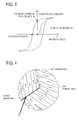
- FIG. 3 is a hysteresis curve of a ferromagnetic body
- FIG. 4 is a pattern diagram illustrating a magnetic domain structure of the ferromagnetic body.
- the coercive force of the permanent magnet is the intensity of a magnetic field needed for bringing the magnetic polarization into zero (that is to say, for magnetization reversal) when the magnetic field is applied from a magnetized state in the opposite direction. Accordingly, if the magnetization reversal can be inhibited, high coercive force can be obtained.
- magnetization processes of a magnetic body include rotational magnetization based on rotation of magnetic moment and domain wall displacement in which domain walls (consisting of a 90-degree domain wall and a 180-degree domain wall) as boundaries of magnetic domains move.
- a sintered magnet such as the Nd-Fe-B-based magnet related to the present invention
- reverse magnetic domain is most likely to occur in the vicinity of the surface of the crystal grain composing a main phase.
- Dy or Tb substitutes for a part of Nd at the surface (outer shell) of a Nd crystal grain 10
- Dy and Tb are both useful elements regarding the effect of improving the coercive force of the Nd 2 Fe 14 B intermetallic compound (i.e., inhibiting magnetization reversal).
- the substitution of Dy or Tb is carried out before compaction of magnet powder through addition of an organometallic compound containing Dy (or Tb) milled as later described.
- the organometallic compound containing the Dy (or Tb) is uniformly adhered to the particle surfaces of the Nd magnet particles by wet dispersion and the Dy (or Tb) included in the organometallic compound diffusively intrudes into the crystal growth region of the Nd magnet particles and substitutes for Nd, to form the Dy layers (or Tb layers) 11 shown in FIG. 2 , when the magnet powder to which the organometallic compound containing Dy (or Tb) is added is sintered.
- Dy (or Tb) is concentrated in a boundary face of the Nd crystal grains 10 as shown in FIG. 4 , thereby enabling the coercive force of the permanent magnet 1 to be improved.
- the organometallic compound containing Dy (or Tb) is expressed by M-(OR) x (in the formula, M represents Dy or Tb, R represents a substituent group consisting of a straight-chain or branched-chain hydrocarbon and x represents an arbitrary integer), and the organometallic compound containing Dy (or Tb) (such as dysprosium ethoxide, dysprosium n-propoxide, terbium ethoxide) is added to an organic solvent and in a wet condition, mixed with the magnet powder.
- the organometallic compound containing Dy (or Tb) is dispersed in the organic solvent, enabling the organometallic compound containing Dy (or Tb) to be adhered onto the particle surfaces of Nd magnet particles effectively.
- metal alkoxide is one of the organometallic compounds that satisfy the above structural formula M-(OR) x (in the formula, M represents Dy or Tb, R represents a substituent group consisting of a straight-chain or branched-chain hydrocarbon and x represents an arbitrary integer) .
- the metal alkoxide is expressed by a general formula M-(OR) n (M: metal element, R: organic group, n: valence of metal or metalloid) .
- examples of metal or metalloid composing the metal alkoxide include W, Mo, V, Nb, Ta, Ti, Zr, Ir, Fe, Co, Ni, Cu, Zn, Cd, Al, Ga, In, Ge, Sb, Y, lanthanide and the like.
- Dy or Tb is specifically used.
- the types of the alkoxide are not specifically limited, and there may be used, for instance, methoxide, ethoxide, propoxide, isopropoxide, butoxide or alkoxide carbon number of which is 4 or larger.
- those of low-molecule weight are used in order to reduce the carbon residue by means of thermal decomposition at a low temperature to be later described.
- methoxide carbon number of which is 1 is prone to decompose and difficult to deal with, therefore it is preferable to use alkoxide carbon number of which is 2 through 6 included in R, such as ethoxide, methoxide, isopropoxide, propoxide or butoxide.
- Dy or Tb is added to the magnet powder, Dy or Tb is present in a state being bound with oxygen contained in the organometallic compound (such as Dy 2 O, DyO and Dy 2 O 3 ).
- the organometallic compound such as Dy 2 O, DyO and Dy 2 O 3 .
- Nd has high reactivity with oxygen
- the presence of oxygen causes Nd to bind with the oxygen to form a Nd oxide at a sintering process.
- Nd has high reactivity with oxygen
- the presence of oxygen causes Nd to bind with the oxygen to form a Nd oxide at a sintering process.
- Nd 2 Fe 14 B the Nd content deficient compared with the content based on the stoichiometric composition. Consequently, alpha iron separates out in the main phase of the sintered magnet, which causes a problem of serious degrade in the magnetic properties.
- the grain size D of the Nd crystal grain 10 is desirable to be approximately 0.1 ⁇ m - 5.0 ⁇ m. Further, by sintering a compact body compacted through powder compaction under appropriate sintering conditions, Nb or Tb can be prevented from being diffused or penetrated (solid-solutionized) into the Nd crystal grains 10. Thereby the present invention can limit the area to be substituted by Dy or Nd in the outer shell portion only, even if Nd or Tb is added.
- the thickness d of Dy layer (or Tb layer) 11 is to be set 1 nm-500 nm, or more preferably, 2 nm-200 nm.
- the Dy layer (or Tb layer) 11 is not required to be a layer composed of only a Dy compound (or Tb compound), and may be a layer composed of a mixture of a Dy compound (or Tb compound) and a Nd compound.
- a layer composed of the mixture of the Dy compound (or Tb compound) and the Nd compound are formed by adding the Nd compound.
- the liquid-phase sintering of the Nd magnet powder can be promoted at the time of sintering.
- the desirable Nd compound to be added may be NdH 2 , neodymium acetate hydrate, neodymium(III) acetylacetonate trihydrate, neodymium(III) 2-ethylhexanoate, neodymium (III) hexafluoroacetylacetonate dihydrate, neodymium isopropoxide, neodymium(III) phosphate n-hydrate, neodymium trifluoroacetylacetonate, and neodymium trifluoromethanesulfonate or the like.
- FIG. 5 is an explanatory view illustrating a manufacturing process in the first method for manufacturing the permanent magnet 1 directed to the present invention.
- Nd-Fe-B of certain fractions for instance, Nd: 32.7 wt%, Fe (electrolytic iron) : 65.96 wt%, and B: 1.34 wt%).
- the ingot is coarsely milled using a stamp mill, a crusher, etc. to a size of approximately 200 ⁇ m. Otherwise, the ingot is dissolved, formed into flakes using a strip-casting method, and then coarsely powdered using a hydrogen pulverization method.
- the coarsely milled magnet powder is finely milled with a jet mill 41 to form fine powder of which the average particle diameter is smaller than a predetermined size (for instance, 0.1 ⁇ m through 5.0 ⁇ m) in: (a) an atmosphere composed of inert gas such as nitrogen gas, argon (Ar) gas, helium (He) gas or the like having an oxygen content of substantially 0 %; or (b) an atmosphere composed of inert gas such as nitrogen gas, Ar gas, He gas or the like having an oxygen content of 0.0001 through 0.5 %.
- a predetermined size for instance, 0.1 ⁇ m through 5.0 ⁇ m
- the term "having an oxygen content of substantially 0 %" is not limited to a case where the oxygen content is completely 0 %, but may include a case where oxygen is contained in such an amount as to allow a slight formation of an oxide film on the surface of the fine powder.
- organometallic compound solution is prepared for adding to the fine powder finely milled by the jet mill 41.
- an organometallic compound containing Dy (or Tb) is added in advance to the organometallic compound solution and dissolved therein.
- an organometallic compound such as dysprosium ethoxide, dysprosium n-propoxide or terbium ethoxide
- M-(OR) x in the formula, M represents Dy or Tb, R represents a straight-chain or branched-chain alkyl group of which carbon number is 2 through 6 and x represents an arbitrary integer.
- the amount of the organometallic compound containing Dy (or Tb) to be dissolved is not particularly limited, however, it is preferably adjusted to such an amount that the Dy (or Tb) content with respect to the sintered magnet is 0.001 wt% through 10 wt%, or more preferably, 0.01 wt% through 5 wt%, as above described.
- the above organometallic compound solution is added to the fine powder classified with the jet mill 41.
- a slurry 42 in which the fine powder of magnet raw material and the organometallic compound solution are mixed is prepared.
- the addition of the organometallic compound solution is performed in an atmosphere composed of inert gas such as nitrogen gas, Ar gas or He gas.
- the prepared slurry 42 is desiccated in advance through vacuum desiccation or the like before compaction and desiccated magnet powder 43 is obtained.
- the desiccated magnet powder 43 undergoes a calcination process by plasma heating with high temperature hydrogen plasma.
- the calcination process is performed by putting the magnet powder 43 into a plasma heating apparatus that utilizes "2.45 GHz high-frequency microwaves".
- application of voltage to the mixed gas of hydrogen gas and inert gas causes plasma excitation so as to irradiate the thus generated high temperature hydrogen plasma on the magnet powder 43 for calcination.
- the flow rate for the supplied gas is within a range of 1 L/min - 10 L/min for hydrogen flow and 1 L/min - 5 L/min for Argon flow.
- the output voltage at plasma excitation is within a range of 1 kW - 10 kW, and the plasma-irradiation period is within a range of 1-60 seconds.
- hydrogen radicals can be generated.
- the hydrogen radicals it becomes possible to perform the reduction to metal Dy and the like or to easily lower the oxidation number in low temperature.
- the concentration of hydrogen radicals can be made higher in a case of using high temperature hydrogen plasma. Accordingly, stable metal oxides (such as Dy 2 O 3 and the like) having low free energy of formation can be appropriately reduced.
- the stable metal oxides with low free energy of formation such as Dy 2 O 3
- it generally requires strong reduction means such as (1) calcium reduction, (2) fused salt electrolysis, (3) laser reduction and the like.
- strong reduction means such as (1) calcium reduction, (2) fused salt electrolysis, (3) laser reduction and the like.
- the object to be reduced is heated to very high temperature. Therefore, if such a method is performed to Nd magnet particles like those in the present invention, there is a risk that the Nd magnet particles may be fused.
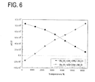
- the calcination by the above high temperature hydrogen plasma heating makes it is possible to form hydrogen radicals in high concentration. Further, as illustrated in FIG. 6 , the lower the temperature is, the stronger reducing character is shown in the reduction by hydrogen radicals.
- the stable metal oxide with low free energy of formation such as Dy 2 O 3 can be reduced in lower temperature than that in the above-mentioned reduction methods (1)-(3).
- practicability of low temperature reduction may be indicated by the fact that the sintered Nd magnet particles are not fused.
- another calcination process (calcination process in hydrogen) may be held for several hours (five hours, for instance) in hydrogen atmosphere at 200 through 900 degrees Celsius, more preferably, 400 through 900 degrees Celsius.
- the timing to perform the calcination process in hydrogen may be either before or after the calcination process by the above plasma heating.
- the calcination process may be performed to magnet powder either before or after the compaction.
- decarbonization is performed in such a manner that carbon content in the calcined body is lowered by causing thermal decomposition to the organometallic compound.
- the calcination process in hydrogen is to be performed under a condition of less than 0.2 wt% carbon content in the calcined body, or more preferably less than 0.1 wt%. Accordingly, the permanent magnet 1 as a whole can be densely sintered in the following sintering process, and the decrease in the residual magnetic flux density and coercive force can be prevented. Furthermore, in a case where the calcination process in hydrogen is performed, a decarbonization process may be performed after the calcination process in order to lower the activity level of the calcined body activated through the calcination process in hydrogen.
- the decarbonization process may be performed by holding the calcined body for 1-3 hours in vacuum atmosphere at 200 through 600 degrees Celsius, more preferably, 400 through 600 degrees Celsius.
- the dehydrogenation process becomes unnecessary.
- the powdered calcined body 65 calcined at the calcination process by the plasma heating is powder-compacted into a predetermined shape by the compaction device 50.
- the compaction device 50 has a cylindrical mold 51, a lower punch 52 and an upper punch 53, and a space surrounded therewith forms a cavity 54.
- a pair of magnetic field generating coils 55 and 56 are disposed in the upper and lower positions of the cavity 54 so as to apply magnetic flux to the calcined body 65 filling the cavity 54.
- the magnetic field to be applied may be, for instance, 10 kOe.
- the cavity 54 is filled with the calcined body 65.
- the lower punch 52 and the upper punch 53 are activated to apply pressure against the calcined body 65 filling the cavity 54 in a pressurizing direction of arrow 61, thereby performing compaction thereof.
- pulsed magnetic field is applied to the calcined body 65 filling the cavity 54, using the magnetic field generating coils 55 and 56, in a direction of arrow 62 which is parallel with the pressuring direction.
- the magnetic field is oriented in a desired direction. Incidentally, it is necessary to determine the direction in which the magnetic field is oriented while taking into consideration the magnetic field orientation required for the permanent magnet 1 formed from the calcined body 65.
- a sintering process for sintering the compacted-state calcined body 65 there is performed a sintering process for sintering the compacted-state calcined body 65.
- a sintering method for a compact body there can be employed, besides commonly-used vacuum sintering, pressure sintering in which the compact body is sintered in a pressured state. For instance, when the sintering is performed in the vacuum sintering, the temperature is risen to approximately 800 through 1080 degrees Celsius in a given rate of temperature increase and held for approximately two hours. During this period, the vacuum sintering is performed, and the degree of vacuum is preferably equal to or smaller than 10 -4 Torr. The compact body is then cooled down, and again undergoes a heat treatment in 600 through 1000 degrees Celsius for two hours. As a result of the sintering, the permanent magnet 1 is manufactured.
- the pressure sintering includes, for instance, hot pressing, hot isostatic pressing (HIP), spark plasma sintering (SPS) and the like.
- HIP hot isostatic pressing
- SPS spark plasma sintering
- the followings are the preferable conditions when the sintering is performed in the SPS; pressure is applied at 30 MPa, the temperature is risen in a rate of 10 degrees Celsius per minute until reaching 940 degrees Celsius in vacuum atmosphere of several Pa or lower and then the state of 940 degrees Celsius in vacuum atmosphere is held for approximately five minutes. The compact body is then cooled down, and again undergoes a heat treatment in 600 through 1000 degrees Celsius for two hours. As a result of the sintering, the permanent magnet 1 is manufactured.
- the prepared slurry 42 is desiccated in advance through vacuum desiccation or the like before compaction and desiccated magnet powder 43 is obtained. Then, the desiccated magnet powder is subjected to powder-compaction to form a given shape using a compaction device 50.
- a compaction device 50 There are dry and wet methods for the powder compaction, and the dry method includes filling a cavity with the desiccated fine powder and the wet method includes preparing slurry of the desiccated fine powder using solvent and then filling a cavity therewith.
- the dry method includes filling a cavity with the desiccated fine powder
- the wet method includes preparing slurry of the desiccated fine powder using solvent and then filling a cavity therewith.
- the organometallic compound solution can be volatilized at the sintering stage after compaction.
- the compaction device 50 may be omitted because manufacturing processes performed here in the second method are the same as those of the first method already described by referring to FIG. 5 .
- slurry may be injected while applying the magnetic field to the cavity 54, and in the course of the injection or after termination of the injection, a magnetic field stronger than the initial magnetic field may be applied to perform the wet molding.
- the magnetic field generating coils 55 and 56 may be disposed so that the application direction of the magnetic field is perpendicular to the pressuring direction.
- a sintering process for sintering the compact body 71 calcined through plasma heating.
- the sintering process is performed by the vacuum sintering or the pressure sintering similar to the above first manufacturing method. Details of the sintering condition are omitted because the manufacturing process here is similar to that of the first manufacturing method already described. As a result of the sintering, the permanent magnet 1 is manufactured.
- both hydrogen feed rate and Argon feed rate are set to 3 L/min.
- the output voltage at plasma excitation is set to 3 kW, and the plasma-irradiation is performed for 60 seconds.
- Sintering of the compacted-state calcined body has been performed in the SPS.
- Other processes are the same as the processes in [First Method for Manufacturing Permanent Magnet] mentioned above.
- Dysprosium n-propoxide has been used as organometallic compound to be added, and sintering has been performed without undergoing a calcination process by plasma heating. Other conditions are the same as the conditions in the embodiment.
- FIG. 8 is a chart depicting spectra detected in a range of 147 eV - 165 eV binding energy, with respect to the permanent magnets of the embodiment and the comparative example.
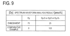
- FIG. 9 is a chart depicting a result of waveform analysis of the spectra of FIG. 8 .
- the permanent magnets of the embodiment and the comparative example have different spectral shapes with each other.
- the mixture proportion with respect to each spectrum is calculated based on the standard sample, and the proportions of Dy, Dy 2 O, DyO and Dy 2 O 3 are depicted respectively in FIG. 9 .
- Dy comprises 75% and Dy oxides (Dy 2 O, DyO and Dy 2 O 3 ) comprise 25% in the permanent magnet of the embodiment, whereas Dy comprises nearly 0% and Dy oxides (Dy 2 O, DyO and Dy 2 O 3 ) comprise nearly 100% in the permanent magnet of the comparative example.
- the Dy oxides Dy 2 O, DyO and Dy 2 O 3
- the Dy oxides can still be reduced to oxides with smaller oxidation number (in other words, the oxidation number can be lowered), so that the oxygen contained in the magnet powder can be decreased in advance.
- the Dy oxide or Tb oxide contained in the magnet powder can be reduced before sintering, so that the oxygen contained in the magnet powder can be reduced in advance.
- the binding of Nd and oxygen and the formation of a Nd oxide in the later sintering process can be prevented. Accordingly, in the permanent magnet of the embodiment, deterioration of the magnet properties due to presence of the metal oxides can be prevented and alpha iron can be prevented from separating out. That is, a permanent magnet with high quality can be obtained. Meanwhile, the permanent magnet of the comparative example has a large proportion of remnant Dy oxides, therefore Nd is likely to bind with oxygen in the sintering process, and Nd oxides are formed. Further, alpha iron separates out in large amount. As a result, deterioration of the magnetic properties occurs in the comparative example.
- an organometallic compound solution is added to fine powder of pulverized neodymium magnet so as to uniformly adhere the organometallic compound to particle surfaces of the neodymium magnet powder, the organometallic compound being expressed with a structural formula of M-(OR) x (M represents Dy or Tb, R represents a substituent group consisting of straight-chain or branched hydrocarbons and x represents an arbitrary integer).
- M represents Dy or Tb
- R represents a substituent group consisting of straight-chain or branched hydrocarbons
- x represents an arbitrary integer
- the entirety of the magnet can be sintered densely.
- Dy or Tb having high magnetic anisotropy is concentrated in a grain boundary of the sintered magnet. Therefore, coercive force can be improved by preventing Dy or Tb, concentrated in the grain boundary, from generating a reverse magnetic domain in the grain boundary. Further, since amount of Dy or Tb added thereto is less in comparison with conventional amount thereof, decline in residual magnetic flux density can be avoided.
- Dy or Tb concentrated in the grain boundaries of a magnet forms a layer of 1 nm - 500 nm, preferably 2 nm - 200 nm in thickness on the surface of each magnet particle after sintering.
- the Nd 2 Fe 14 B intermetallic compound phase of the core constitutes a significant fraction of the whole crystal grains (in other words, the whole sintered magnet). Accordingly, there can be prevented the decrease of the residual magnetic flux density (magnetic flux density when the external magnetic field is made to be 0) in the permanent magnet.
- the organometallic-compound-added magnet powder or the compact body is calcined by utilizing plasma heating prior to sintering. Thereby, such mannered manufacturing process makes it possible to reduce Dy or Tb present therein in a state bound with oxygen to metal Dy or metal Tb, or to an oxide with smaller oxidation number such as DyO, etc.
- the magnet powder or compact body can be calcined under an appropriate condition using plasma heating, so that the oxygen content contained in the magnet particle can be more reliably decreased.
- high temperature hydrogen plasma heating is applied as specific means for calcination, high concentration of hydrogen radicals can be generated.
- the metal forming an organometallic compound is present in the magnet powder in a state of a stable oxide, the reduction to a metal or lowering of the oxidation number thereof can be easily performed at a low temperature using the hydrogen radicals.
- the calcination process is performed to the powdered magnet particles, which is advantageous in that the reduction of metal oxides can be performed more easily to the whole magnet particles, compared with the case where the magnet particles are calcined after compaction. That is, compared with the second manufacturing method, the oxygen content in the calcined body can be more reliably decreased.
- the organometallic compound to be added is specifically chosen from the organometallic compound composed of alkyl group, or more preferably an organometallic compound composed of alkyl group of carbon number 2-6, thermal decomposition of the organometallic compound can be caused at a low temperature when the magnet powder or the compact body is calcined in hydrogen atmosphere. Thereby, thermal decomposition of the organometallic compound can easily be caused to the whole magnet powder or the whole compact body. Accordingly, such mannered manufacturing process can prevent alpha iron from separating out within the main phase of the magnet after sintering. Thereby, the whole magnet can be densely sintered and the lowering of the coercive force can be prevented.
- the present invention is not limited to the above-described embodiment but may be variously improved and modified without departing from the scope of the present invention. Further, of magnet powder, milling condition, mixing condition, calcination condition, dehydrogenation condition, sintering condition, etc. are not restricted to conditions described in the embodiment.
- dysprosium n-propoxide is used as Dy-or-Tb-inclusive organometallic compound that is to be added to magnet powder.
- Other organometallic compounds may be used as long as being an organometallic compound that satisfies an expression of M- (OR) x (M represents Dy or Tb, R represents a substituent group consisting of a straight-chain or branched-chain hydrocarbon, and represents an arbitrary integer).
- M represents Dy or Tb
- R represents a substituent group consisting of a straight-chain or branched-chain hydrocarbon, and represents an arbitrary integer.
- an organometallic compound of which carbon number is 7 or larger and an organometallic compound including a substituent group consisting of carbon hydride other than an alkyl group.
Landscapes
- Engineering & Computer Science (AREA)
- Power Engineering (AREA)
- Manufacturing & Machinery (AREA)
- Chemical & Material Sciences (AREA)
- Crystallography & Structural Chemistry (AREA)
- Inorganic Chemistry (AREA)
- Mechanical Engineering (AREA)
- Hard Magnetic Materials (AREA)
- Powder Metallurgy (AREA)
- Manufacturing Cores, Coils, And Magnets (AREA)
Applications Claiming Priority (2)
| Application Number | Priority Date | Filing Date | Title |
|---|---|---|---|
| JP2010084156 | 2010-03-31 | ||
| PCT/JP2011/057575 WO2011125594A1 (ja) | 2010-03-31 | 2011-03-28 | 永久磁石及び永久磁石の製造方法 |
Publications (3)
| Publication Number | Publication Date |
|---|---|
| EP2503572A1 true EP2503572A1 (de) | 2012-09-26 |
| EP2503572A4 EP2503572A4 (de) | 2012-12-05 |
| EP2503572B1 EP2503572B1 (de) | 2015-03-25 |
Family
ID=44762543
Family Applications (1)
| Application Number | Title | Priority Date | Filing Date |
|---|---|---|---|
| EP11765494.7A Not-in-force EP2503572B1 (de) | 2010-03-31 | 2011-03-28 | Verfahren zur herstellung eines permanentmagneten |
Country Status (7)
| Country | Link |
|---|---|
| US (1) | US8480816B2 (de) |
| EP (1) | EP2503572B1 (de) |
| JP (1) | JP4865919B2 (de) |
| KR (1) | KR101165937B1 (de) |
| CN (1) | CN102549685B (de) |
| TW (1) | TW201218220A (de) |
| WO (1) | WO2011125594A1 (de) |
Cited By (1)
| Publication number | Priority date | Publication date | Assignee | Title |
|---|---|---|---|---|
| EP3373315A4 (de) * | 2015-11-02 | 2018-09-12 | Nissan Motor Co., Ltd. | Korngrenzenreformierungsverfahren für nd-fe-b-basierten magnet und mit diesem verfahren bearbeiteter korngrenzenreformierter körper |
Families Citing this family (9)
| Publication number | Priority date | Publication date | Assignee | Title |
|---|---|---|---|---|
| JP5417632B2 (ja) * | 2008-03-18 | 2014-02-19 | 日東電工株式会社 | 永久磁石及び永久磁石の製造方法 |
| US20120181476A1 (en) * | 2010-03-31 | 2012-07-19 | Nitto Denko Corporation | Permanent magnet and manufacturing method thereof |
| WO2011125584A1 (ja) * | 2010-03-31 | 2011-10-13 | 日東電工株式会社 | 永久磁石及び永久磁石の製造方法 |
| JP5011420B2 (ja) * | 2010-05-14 | 2012-08-29 | 日東電工株式会社 | 永久磁石及び永久磁石の製造方法 |
| JP5908247B2 (ja) * | 2011-09-30 | 2016-04-26 | 日東電工株式会社 | 永久磁石の製造方法 |
| DE102013004985A1 (de) * | 2012-11-14 | 2014-05-15 | Volkswagen Aktiengesellschaft | Verfahren zur Herstellung eines Permanentmagneten sowie Permanentmagnet |
| KR101543111B1 (ko) * | 2013-12-17 | 2015-08-10 | 현대자동차주식회사 | NdFeB 영구자석 및 그 제조방법 |
| FR3051992A1 (fr) * | 2016-05-25 | 2017-12-01 | Valeo Equip Electr Moteur | Machine electrique tournante munie d'aimants en terre rare a faible taux de dysprosium |
| FR3051991B1 (fr) * | 2016-05-25 | 2018-07-06 | Valeo Equipements Electriques Moteur | Rotor de machine electrique tournante muni d'aimants en terre rare a faible taux de dysprosium |
Family Cites Families (20)
| Publication number | Priority date | Publication date | Assignee | Title |
|---|---|---|---|---|
| JP2753321B2 (ja) * | 1989-04-10 | 1998-05-20 | 株式会社日立製作所 | 光情報再生方法及び装置 |
| JP3298219B2 (ja) | 1993-03-17 | 2002-07-02 | 日立金属株式会社 | 希土類―Fe−Co−Al−V−Ga−B系焼結磁石 |
| JP2001020065A (ja) | 1999-07-07 | 2001-01-23 | Hitachi Metals Ltd | スパッタリング用ターゲット及びその製造方法ならびに高融点金属粉末材料 |
| ATE555485T1 (de) * | 2001-01-30 | 2012-05-15 | Hitachi Metals Ltd | Verfahren zur herstellung eines permanentmagneten |
| JP4374962B2 (ja) | 2003-03-28 | 2009-12-02 | 日産自動車株式会社 | 希土類磁石およびその製造方法、ならびに希土類磁石を用いてなるモータ |
| US7618497B2 (en) * | 2003-06-30 | 2009-11-17 | Tdk Corporation | R-T-B based rare earth permanent magnet and method for production thereof |
| JP2005039089A (ja) | 2003-07-16 | 2005-02-10 | Neomax Co Ltd | 微粒子を用いるナノ結晶磁石の製造方法 |
| JP2005097697A (ja) | 2003-09-26 | 2005-04-14 | Toshiba Corp | スパッタリングターゲットとその製造方法 |
| JP4525072B2 (ja) * | 2003-12-22 | 2010-08-18 | 日産自動車株式会社 | 希土類磁石およびその製造方法 |
| JP2005191187A (ja) * | 2003-12-25 | 2005-07-14 | Nissan Motor Co Ltd | 希土類磁石およびその製造方法 |
| JP2005197299A (ja) * | 2003-12-26 | 2005-07-21 | Tdk Corp | 希土類焼結磁石及びその製造方法 |
| JP5417632B2 (ja) | 2008-03-18 | 2014-02-19 | 日東電工株式会社 | 永久磁石及び永久磁石の製造方法 |
| JP4872109B2 (ja) * | 2008-03-18 | 2012-02-08 | 日東電工株式会社 | 永久磁石及び永久磁石の製造方法 |
| CN101978321B (zh) | 2008-03-21 | 2013-06-12 | 旭化成电子材料株式会社 | 感光性树脂组合物、感光性树脂层压体、抗蚀图案形成方法、以及印刷线路板、引线框、半导体封装体和凹凸基板的制造方法 |
| JP5261747B2 (ja) * | 2008-04-15 | 2013-08-14 | 日東電工株式会社 | 永久磁石及び永久磁石の製造方法 |
| EP2503567B1 (de) * | 2010-03-31 | 2014-07-02 | Nitto Denko Corporation | Verfahren zur herstellung eines permanentmagneten |
| WO2011125584A1 (ja) * | 2010-03-31 | 2011-10-13 | 日東電工株式会社 | 永久磁石及び永久磁石の製造方法 |
| JP4923152B2 (ja) * | 2010-03-31 | 2012-04-25 | 日東電工株式会社 | 永久磁石及び永久磁石の製造方法 |
| WO2011125582A1 (ja) * | 2010-03-31 | 2011-10-13 | 日東電工株式会社 | 永久磁石及び永久磁石の製造方法 |
| US20120181476A1 (en) * | 2010-03-31 | 2012-07-19 | Nitto Denko Corporation | Permanent magnet and manufacturing method thereof |
-
2011
- 2011-03-28 CN CN201180003973.5A patent/CN102549685B/zh not_active Expired - Fee Related
- 2011-03-28 EP EP11765494.7A patent/EP2503572B1/de not_active Not-in-force
- 2011-03-28 JP JP2011069071A patent/JP4865919B2/ja not_active Expired - Fee Related
- 2011-03-28 WO PCT/JP2011/057575 patent/WO2011125594A1/ja not_active Ceased
- 2011-03-28 KR KR1020127007185A patent/KR101165937B1/ko not_active Expired - Fee Related
- 2011-03-28 US US13/499,434 patent/US8480816B2/en not_active Expired - Fee Related
- 2011-03-31 TW TW100111410A patent/TW201218220A/zh not_active IP Right Cessation
Cited By (1)
| Publication number | Priority date | Publication date | Assignee | Title |
|---|---|---|---|---|
| EP3373315A4 (de) * | 2015-11-02 | 2018-09-12 | Nissan Motor Co., Ltd. | Korngrenzenreformierungsverfahren für nd-fe-b-basierten magnet und mit diesem verfahren bearbeiteter korngrenzenreformierter körper |
Also Published As
| Publication number | Publication date |
|---|---|
| KR20120049355A (ko) | 2012-05-16 |
| EP2503572B1 (de) | 2015-03-25 |
| US20120182105A1 (en) | 2012-07-19 |
| TW201218220A (en) | 2012-05-01 |
| TWI371048B (de) | 2012-08-21 |
| KR101165937B1 (ko) | 2012-07-20 |
| US8480816B2 (en) | 2013-07-09 |
| WO2011125594A1 (ja) | 2011-10-13 |
| CN102549685B (zh) | 2014-04-02 |
| CN102549685A (zh) | 2012-07-04 |
| JP2011228663A (ja) | 2011-11-10 |
| EP2503572A4 (de) | 2012-12-05 |
| JP4865919B2 (ja) | 2012-02-01 |
Similar Documents
| Publication | Publication Date | Title |
|---|---|---|
| EP2503572B1 (de) | Verfahren zur herstellung eines permanentmagneten | |
| EP2503573B1 (de) | Verfahren zur herstellung eines permanentmagneten | |
| US9053846B2 (en) | Permanent magnet and manufacturing method thereof | |
| US9005374B2 (en) | Permanent magnet and manufacturing method thereof | |
| US8491728B2 (en) | Permanent magnet and manufacturing method thereof | |
| EP2506274B1 (de) | Verfahren zur herstellung eines permanentmagneten | |
| US8500921B2 (en) | Permanent magnet and manufacturing method thereof | |
| EP2503561B1 (de) | Verfahren zur herstellung eines permanentmagneten | |
| EP2503566B1 (de) | Verfahren zur herstellung eines permanentmagneten | |
| EP2503569A1 (de) | Permanentmagnet und verfahren zur herstellung eines permanentmagneten | |
| US9048014B2 (en) | Permanent magnet and manufacturing method thereof | |
| US20140301885A1 (en) | Permanent magnet and method for manufacturing permanent magnet | |
| US8480818B2 (en) | Permanent magnet and manufacturing method thereof | |
| EP2503565B1 (de) | Verfahren zur herstellung eines permanentmagneten |
Legal Events
| Date | Code | Title | Description |
|---|---|---|---|
| PUAI | Public reference made under article 153(3) epc to a published international application that has entered the european phase |
Free format text: ORIGINAL CODE: 0009012 |
|
| 17P | Request for examination filed |
Effective date: 20120328 |
|
| AK | Designated contracting states |
Kind code of ref document: A1 Designated state(s): AL AT BE BG CH CY CZ DE DK EE ES FI FR GB GR HR HU IE IS IT LI LT LU LV MC MK MT NL NO PL PT RO RS SE SI SK SM TR |
|
| A4 | Supplementary search report drawn up and despatched |
Effective date: 20121107 |
|
| RIC1 | Information provided on ipc code assigned before grant |
Ipc: C21D 1/34 20060101ALI20121101BHEP Ipc: H01F 1/08 20060101ALI20121101BHEP Ipc: B22F 1/02 20060101ALI20121101BHEP Ipc: B22F 3/02 20060101ALI20121101BHEP Ipc: C22C 33/02 20060101ALI20121101BHEP Ipc: C22C 38/00 20060101ALI20121101BHEP Ipc: C21D 1/38 20060101ALI20121101BHEP Ipc: H01F 41/02 20060101AFI20121101BHEP Ipc: H01F 1/057 20060101ALI20121101BHEP Ipc: H01F 1/053 20060101ALI20121101BHEP Ipc: B22F 3/00 20060101ALI20121101BHEP Ipc: B22F 1/00 20060101ALI20121101BHEP |
|
| DAX | Request for extension of the european patent (deleted) | ||
| 17Q | First examination report despatched |
Effective date: 20140515 |
|
| GRAP | Despatch of communication of intention to grant a patent |
Free format text: ORIGINAL CODE: EPIDOSNIGR1 |
|
| INTG | Intention to grant announced |
Effective date: 20141010 |
|
| GRAS | Grant fee paid |
Free format text: ORIGINAL CODE: EPIDOSNIGR3 |
|
| GRAA | (expected) grant |
Free format text: ORIGINAL CODE: 0009210 |
|
| AK | Designated contracting states |
Kind code of ref document: B1 Designated state(s): AL AT BE BG CH CY CZ DE DK EE ES FI FR GB GR HR HU IE IS IT LI LT LU LV MC MK MT NL NO PL PT RO RS SE SI SK SM TR |
|
| REG | Reference to a national code |
Ref country code: GB Ref legal event code: FG4D |
|
| REG | Reference to a national code |
Ref country code: CH Ref legal event code: EP |
|
| REG | Reference to a national code |
Ref country code: IE Ref legal event code: FG4D |
|
| REG | Reference to a national code |
Ref country code: DE Ref legal event code: R096 Ref document number: 602011015073 Country of ref document: DE Effective date: 20150507 |
|
| REG | Reference to a national code |
Ref country code: AT Ref legal event code: REF Ref document number: 718288 Country of ref document: AT Kind code of ref document: T Effective date: 20150515 |
|
| PG25 | Lapsed in a contracting state [announced via postgrant information from national office to epo] |
Ref country code: FI Free format text: LAPSE BECAUSE OF FAILURE TO SUBMIT A TRANSLATION OF THE DESCRIPTION OR TO PAY THE FEE WITHIN THE PRESCRIBED TIME-LIMIT Effective date: 20150325 Ref country code: LT Free format text: LAPSE BECAUSE OF FAILURE TO SUBMIT A TRANSLATION OF THE DESCRIPTION OR TO PAY THE FEE WITHIN THE PRESCRIBED TIME-LIMIT Effective date: 20150325 Ref country code: SE Free format text: LAPSE BECAUSE OF FAILURE TO SUBMIT A TRANSLATION OF THE DESCRIPTION OR TO PAY THE FEE WITHIN THE PRESCRIBED TIME-LIMIT Effective date: 20150325 Ref country code: HR Free format text: LAPSE BECAUSE OF FAILURE TO SUBMIT A TRANSLATION OF THE DESCRIPTION OR TO PAY THE FEE WITHIN THE PRESCRIBED TIME-LIMIT Effective date: 20150325 |
|
| REG | Reference to a national code |
Ref country code: AT Ref legal event code: MK05 Ref document number: 718288 Country of ref document: AT Kind code of ref document: T Effective date: 20150325 |
|
| REG | Reference to a national code |
Ref country code: LT Ref legal event code: MG4D |
|
| PG25 | Lapsed in a contracting state [announced via postgrant information from national office to epo] |
Ref country code: RS Free format text: LAPSE BECAUSE OF FAILURE TO SUBMIT A TRANSLATION OF THE DESCRIPTION OR TO PAY THE FEE WITHIN THE PRESCRIBED TIME-LIMIT Effective date: 20150325 Ref country code: GR Free format text: LAPSE BECAUSE OF FAILURE TO SUBMIT A TRANSLATION OF THE DESCRIPTION OR TO PAY THE FEE WITHIN THE PRESCRIBED TIME-LIMIT Effective date: 20150626 Ref country code: LV Free format text: LAPSE BECAUSE OF FAILURE TO SUBMIT A TRANSLATION OF THE DESCRIPTION OR TO PAY THE FEE WITHIN THE PRESCRIBED TIME-LIMIT Effective date: 20150325 |
|
| PG25 | Lapsed in a contracting state [announced via postgrant information from national office to epo] |
Ref country code: NL Free format text: LAPSE BECAUSE OF FAILURE TO SUBMIT A TRANSLATION OF THE DESCRIPTION OR TO PAY THE FEE WITHIN THE PRESCRIBED TIME-LIMIT Effective date: 20150325 |
|
| PG25 | Lapsed in a contracting state [announced via postgrant information from national office to epo] |
Ref country code: RO Free format text: LAPSE BECAUSE OF FAILURE TO SUBMIT A TRANSLATION OF THE DESCRIPTION OR TO PAY THE FEE WITHIN THE PRESCRIBED TIME-LIMIT Effective date: 20150325 Ref country code: CZ Free format text: LAPSE BECAUSE OF FAILURE TO SUBMIT A TRANSLATION OF THE DESCRIPTION OR TO PAY THE FEE WITHIN THE PRESCRIBED TIME-LIMIT Effective date: 20150325 Ref country code: EE Free format text: LAPSE BECAUSE OF FAILURE TO SUBMIT A TRANSLATION OF THE DESCRIPTION OR TO PAY THE FEE WITHIN THE PRESCRIBED TIME-LIMIT Effective date: 20150325 Ref country code: PT Free format text: LAPSE BECAUSE OF FAILURE TO SUBMIT A TRANSLATION OF THE DESCRIPTION OR TO PAY THE FEE WITHIN THE PRESCRIBED TIME-LIMIT Effective date: 20150727 Ref country code: ES Free format text: LAPSE BECAUSE OF FAILURE TO SUBMIT A TRANSLATION OF THE DESCRIPTION OR TO PAY THE FEE WITHIN THE PRESCRIBED TIME-LIMIT Effective date: 20150325 Ref country code: SK Free format text: LAPSE BECAUSE OF FAILURE TO SUBMIT A TRANSLATION OF THE DESCRIPTION OR TO PAY THE FEE WITHIN THE PRESCRIBED TIME-LIMIT Effective date: 20150325 |
|
| REG | Reference to a national code |
Ref country code: CH Ref legal event code: PL |
|
| PG25 | Lapsed in a contracting state [announced via postgrant information from national office to epo] |
Ref country code: IS Free format text: LAPSE BECAUSE OF FAILURE TO SUBMIT A TRANSLATION OF THE DESCRIPTION OR TO PAY THE FEE WITHIN THE PRESCRIBED TIME-LIMIT Effective date: 20150725 Ref country code: PL Free format text: LAPSE BECAUSE OF FAILURE TO SUBMIT A TRANSLATION OF THE DESCRIPTION OR TO PAY THE FEE WITHIN THE PRESCRIBED TIME-LIMIT Effective date: 20150325 Ref country code: AT Free format text: LAPSE BECAUSE OF FAILURE TO SUBMIT A TRANSLATION OF THE DESCRIPTION OR TO PAY THE FEE WITHIN THE PRESCRIBED TIME-LIMIT Effective date: 20150325 |
|
| PG25 | Lapsed in a contracting state [announced via postgrant information from national office to epo] |
Ref country code: IT Free format text: LAPSE BECAUSE OF FAILURE TO SUBMIT A TRANSLATION OF THE DESCRIPTION OR TO PAY THE FEE WITHIN THE PRESCRIBED TIME-LIMIT Effective date: 20150325 |
|
| REG | Reference to a national code |
Ref country code: DE Ref legal event code: R097 Ref document number: 602011015073 Country of ref document: DE |
|
| REG | Reference to a national code |
Ref country code: IE Ref legal event code: MM4A |
|
| PG25 | Lapsed in a contracting state [announced via postgrant information from national office to epo] |
Ref country code: LI Free format text: LAPSE BECAUSE OF NON-PAYMENT OF DUE FEES Effective date: 20150331 Ref country code: IE Free format text: LAPSE BECAUSE OF NON-PAYMENT OF DUE FEES Effective date: 20150328 Ref country code: CH Free format text: LAPSE BECAUSE OF NON-PAYMENT OF DUE FEES Effective date: 20150331 Ref country code: MC Free format text: LAPSE BECAUSE OF FAILURE TO SUBMIT A TRANSLATION OF THE DESCRIPTION OR TO PAY THE FEE WITHIN THE PRESCRIBED TIME-LIMIT Effective date: 20150325 Ref country code: DK Free format text: LAPSE BECAUSE OF FAILURE TO SUBMIT A TRANSLATION OF THE DESCRIPTION OR TO PAY THE FEE WITHIN THE PRESCRIBED TIME-LIMIT Effective date: 20150325 |
|
| PLBE | No opposition filed within time limit |
Free format text: ORIGINAL CODE: 0009261 |
|
| STAA | Information on the status of an ep patent application or granted ep patent |
Free format text: STATUS: NO OPPOSITION FILED WITHIN TIME LIMIT |
|
| REG | Reference to a national code |
Ref country code: FR Ref legal event code: PLFP Year of fee payment: 6 |
|
| GBPC | Gb: european patent ceased through non-payment of renewal fee |
Effective date: 20150625 |
|
| 26N | No opposition filed |
Effective date: 20160105 |
|
| PG25 | Lapsed in a contracting state [announced via postgrant information from national office to epo] |
Ref country code: GB Free format text: LAPSE BECAUSE OF NON-PAYMENT OF DUE FEES Effective date: 20150625 |
|
| PG25 | Lapsed in a contracting state [announced via postgrant information from national office to epo] |
Ref country code: SI Free format text: LAPSE BECAUSE OF FAILURE TO SUBMIT A TRANSLATION OF THE DESCRIPTION OR TO PAY THE FEE WITHIN THE PRESCRIBED TIME-LIMIT Effective date: 20150325 |
|
| PG25 | Lapsed in a contracting state [announced via postgrant information from national office to epo] |
Ref country code: MT Free format text: LAPSE BECAUSE OF FAILURE TO SUBMIT A TRANSLATION OF THE DESCRIPTION OR TO PAY THE FEE WITHIN THE PRESCRIBED TIME-LIMIT Effective date: 20150325 |
|
| REG | Reference to a national code |
Ref country code: FR Ref legal event code: PLFP Year of fee payment: 7 |
|
| PGFP | Annual fee paid to national office [announced via postgrant information from national office to epo] |
Ref country code: DE Payment date: 20170321 Year of fee payment: 7 Ref country code: FR Payment date: 20170213 Year of fee payment: 7 |
|
| PG25 | Lapsed in a contracting state [announced via postgrant information from national office to epo] |
Ref country code: BG Free format text: LAPSE BECAUSE OF FAILURE TO SUBMIT A TRANSLATION OF THE DESCRIPTION OR TO PAY THE FEE WITHIN THE PRESCRIBED TIME-LIMIT Effective date: 20150325 Ref country code: HU Free format text: LAPSE BECAUSE OF FAILURE TO SUBMIT A TRANSLATION OF THE DESCRIPTION OR TO PAY THE FEE WITHIN THE PRESCRIBED TIME-LIMIT; INVALID AB INITIO Effective date: 20110328 Ref country code: NO Free format text: LAPSE BECAUSE OF FAILURE TO SUBMIT A TRANSLATION OF THE DESCRIPTION OR TO PAY THE FEE WITHIN THE PRESCRIBED TIME-LIMIT Effective date: 20150625 Ref country code: SM Free format text: LAPSE BECAUSE OF FAILURE TO SUBMIT A TRANSLATION OF THE DESCRIPTION OR TO PAY THE FEE WITHIN THE PRESCRIBED TIME-LIMIT Effective date: 20150325 |
|
| PGFP | Annual fee paid to national office [announced via postgrant information from national office to epo] |
Ref country code: BE Payment date: 20170213 Year of fee payment: 7 |
|
| PG25 | Lapsed in a contracting state [announced via postgrant information from national office to epo] |
Ref country code: CY Free format text: LAPSE BECAUSE OF FAILURE TO SUBMIT A TRANSLATION OF THE DESCRIPTION OR TO PAY THE FEE WITHIN THE PRESCRIBED TIME-LIMIT Effective date: 20150325 |
|
| PG25 | Lapsed in a contracting state [announced via postgrant information from national office to epo] |
Ref country code: TR Free format text: LAPSE BECAUSE OF FAILURE TO SUBMIT A TRANSLATION OF THE DESCRIPTION OR TO PAY THE FEE WITHIN THE PRESCRIBED TIME-LIMIT Effective date: 20150325 |
|
| PG25 | Lapsed in a contracting state [announced via postgrant information from national office to epo] |
Ref country code: LU Free format text: LAPSE BECAUSE OF NON-PAYMENT OF DUE FEES Effective date: 20150328 |
|
| PG25 | Lapsed in a contracting state [announced via postgrant information from national office to epo] |
Ref country code: MK Free format text: LAPSE BECAUSE OF FAILURE TO SUBMIT A TRANSLATION OF THE DESCRIPTION OR TO PAY THE FEE WITHIN THE PRESCRIBED TIME-LIMIT Effective date: 20150325 |
|
| REG | Reference to a national code |
Ref country code: DE Ref legal event code: R119 Ref document number: 602011015073 Country of ref document: DE |
|
| PG25 | Lapsed in a contracting state [announced via postgrant information from national office to epo] |
Ref country code: AL Free format text: LAPSE BECAUSE OF FAILURE TO SUBMIT A TRANSLATION OF THE DESCRIPTION OR TO PAY THE FEE WITHIN THE PRESCRIBED TIME-LIMIT Effective date: 20150325 |
|
| REG | Reference to a national code |
Ref country code: BE Ref legal event code: FP Effective date: 20150401 Ref country code: BE Ref legal event code: MM Effective date: 20180331 |
|
| PG25 | Lapsed in a contracting state [announced via postgrant information from national office to epo] |
Ref country code: DE Free format text: LAPSE BECAUSE OF NON-PAYMENT OF DUE FEES Effective date: 20181002 |
|
| PG25 | Lapsed in a contracting state [announced via postgrant information from national office to epo] |
Ref country code: BE Free format text: LAPSE BECAUSE OF NON-PAYMENT OF DUE FEES Effective date: 20180331 |
|
| PG25 | Lapsed in a contracting state [announced via postgrant information from national office to epo] |
Ref country code: FR Free format text: LAPSE BECAUSE OF NON-PAYMENT OF DUE FEES Effective date: 20180331 |