EP2503323A2 - Dispositif et procédé de mesure de la répartition spatiale de gaz atmosphériques à proximité du sol - Google Patents
Dispositif et procédé de mesure de la répartition spatiale de gaz atmosphériques à proximité du sol Download PDFInfo
- Publication number
- EP2503323A2 EP2503323A2 EP12161125A EP12161125A EP2503323A2 EP 2503323 A2 EP2503323 A2 EP 2503323A2 EP 12161125 A EP12161125 A EP 12161125A EP 12161125 A EP12161125 A EP 12161125A EP 2503323 A2 EP2503323 A2 EP 2503323A2
- Authority
- EP
- European Patent Office
- Prior art keywords
- spectrometer
- measuring
- distribution space
- rotating mirror
- retroreflectors
- Prior art date
- Legal status (The legal status is an assumption and is not a legal conclusion. Google has not performed a legal analysis and makes no representation as to the accuracy of the status listed.)
- Withdrawn
Links
- 238000009826 distribution Methods 0.000 title claims abstract description 57
- 238000000034 method Methods 0.000 title claims abstract description 21
- 239000007789 gas Substances 0.000 title claims abstract description 17
- 238000005259 measurement Methods 0.000 claims description 20
- 238000010905 molecular spectroscopy Methods 0.000 claims description 4
- 238000007493 shaping process Methods 0.000 claims description 2
- 230000000007 visual effect Effects 0.000 claims description 2
- 238000001514 detection method Methods 0.000 description 4
- 238000003325 tomography Methods 0.000 description 4
- 238000013459 approach Methods 0.000 description 3
- 230000003287 optical effect Effects 0.000 description 3
- 230000003595 spectral effect Effects 0.000 description 3
- XLYOFNOQVPJJNP-UHFFFAOYSA-N water Substances O XLYOFNOQVPJJNP-UHFFFAOYSA-N 0.000 description 3
- CURLTUGMZLYLDI-UHFFFAOYSA-N Carbon dioxide Chemical compound O=C=O CURLTUGMZLYLDI-UHFFFAOYSA-N 0.000 description 2
- 229910000831 Steel Inorganic materials 0.000 description 2
- 230000005540 biological transmission Effects 0.000 description 2
- 230000001419 dependent effect Effects 0.000 description 2
- VNWKTOKETHGBQD-UHFFFAOYSA-N methane Chemical compound C VNWKTOKETHGBQD-UHFFFAOYSA-N 0.000 description 2
- 239000000203 mixture Substances 0.000 description 2
- 239000010959 steel Substances 0.000 description 2
- RWSOTUBLDIXVET-UHFFFAOYSA-N Dihydrogen sulfide Chemical compound S RWSOTUBLDIXVET-UHFFFAOYSA-N 0.000 description 1
- 238000010521 absorption reaction Methods 0.000 description 1
- 229910002092 carbon dioxide Inorganic materials 0.000 description 1
- 239000001569 carbon dioxide Substances 0.000 description 1
- 230000005494 condensation Effects 0.000 description 1
- 238000009833 condensation Methods 0.000 description 1
- 238000010276 construction Methods 0.000 description 1
- 238000001658 differential optical absorption spectrophotometry Methods 0.000 description 1
- 230000000694 effects Effects 0.000 description 1
- 238000005516 engineering process Methods 0.000 description 1
- 230000008020 evaporation Effects 0.000 description 1
- 238000001704 evaporation Methods 0.000 description 1
- 230000005484 gravity Effects 0.000 description 1
- 229910000037 hydrogen sulfide Inorganic materials 0.000 description 1
- 230000000155 isotopic effect Effects 0.000 description 1
- 230000007774 longterm Effects 0.000 description 1
- 238000012544 monitoring process Methods 0.000 description 1
- 238000000623 plasma-assisted chemical vapour deposition Methods 0.000 description 1
- 230000005855 radiation Effects 0.000 description 1
- 239000002689 soil Substances 0.000 description 1
- 238000004158 soil respiration Methods 0.000 description 1
- 238000003860 storage Methods 0.000 description 1
- 238000000041 tunable diode laser absorption spectroscopy Methods 0.000 description 1
- 238000007740 vapor deposition Methods 0.000 description 1
Images


Classifications
-
- G—PHYSICS
- G01—MEASURING; TESTING
- G01N—INVESTIGATING OR ANALYSING MATERIALS BY DETERMINING THEIR CHEMICAL OR PHYSICAL PROPERTIES
- G01N21/00—Investigating or analysing materials by the use of optical means, i.e. using sub-millimetre waves, infrared, visible or ultraviolet light
- G01N21/17—Systems in which incident light is modified in accordance with the properties of the material investigated
- G01N21/25—Colour; Spectral properties, i.e. comparison of effect of material on the light at two or more different wavelengths or wavelength bands
- G01N21/31—Investigating relative effect of material at wavelengths characteristic of specific elements or molecules, e.g. atomic absorption spectrometry
- G01N21/35—Investigating relative effect of material at wavelengths characteristic of specific elements or molecules, e.g. atomic absorption spectrometry using infrared light
- G01N21/3504—Investigating relative effect of material at wavelengths characteristic of specific elements or molecules, e.g. atomic absorption spectrometry using infrared light for analysing gases, e.g. multi-gas analysis
-
- G—PHYSICS
- G01—MEASURING; TESTING
- G01N—INVESTIGATING OR ANALYSING MATERIALS BY DETERMINING THEIR CHEMICAL OR PHYSICAL PROPERTIES
- G01N21/00—Investigating or analysing materials by the use of optical means, i.e. using sub-millimetre waves, infrared, visible or ultraviolet light
- G01N21/17—Systems in which incident light is modified in accordance with the properties of the material investigated
- G01N2021/178—Methods for obtaining spatial resolution of the property being measured
- G01N2021/1785—Three dimensional
- G01N2021/1787—Tomographic, i.e. computerised reconstruction from projective measurements
-
- G—PHYSICS
- G01—MEASURING; TESTING
- G01N—INVESTIGATING OR ANALYSING MATERIALS BY DETERMINING THEIR CHEMICAL OR PHYSICAL PROPERTIES
- G01N21/00—Investigating or analysing materials by the use of optical means, i.e. using sub-millimetre waves, infrared, visible or ultraviolet light
- G01N21/17—Systems in which incident light is modified in accordance with the properties of the material investigated
- G01N2021/1793—Remote sensing
- G01N2021/1795—Atmospheric mapping of gases
-
- G—PHYSICS
- G01—MEASURING; TESTING
- G01N—INVESTIGATING OR ANALYSING MATERIALS BY DETERMINING THEIR CHEMICAL OR PHYSICAL PROPERTIES
- G01N21/00—Investigating or analysing materials by the use of optical means, i.e. using sub-millimetre waves, infrared, visible or ultraviolet light
- G01N21/17—Systems in which incident light is modified in accordance with the properties of the material investigated
- G01N21/25—Colour; Spectral properties, i.e. comparison of effect of material on the light at two or more different wavelengths or wavelength bands
- G01N21/31—Investigating relative effect of material at wavelengths characteristic of specific elements or molecules, e.g. atomic absorption spectrometry
- G01N21/35—Investigating relative effect of material at wavelengths characteristic of specific elements or molecules, e.g. atomic absorption spectrometry using infrared light
- G01N21/3504—Investigating relative effect of material at wavelengths characteristic of specific elements or molecules, e.g. atomic absorption spectrometry using infrared light for analysing gases, e.g. multi-gas analysis
- G01N2021/3513—Open path with an instrumental source
-
- G—PHYSICS
- G01—MEASURING; TESTING
- G01N—INVESTIGATING OR ANALYSING MATERIALS BY DETERMINING THEIR CHEMICAL OR PHYSICAL PROPERTIES
- G01N2201/00—Features of devices classified in G01N21/00
- G01N2201/10—Scanning
- G01N2201/105—Purely optical scan
Definitions
- the invention relates to an apparatus and a method for measuring the spatial distribution of concentrations of atmospheric gases on the field scale by means of tomographic molecular spectroscopy.
- US-A-3925666 a detection system for the measurement of hydrogen sulfide in rooms is known, with which a potential leak in a stored in a room storage can be detected.
- the detection system consists of several transmitting units, mirrors, retroreflectors and detector units, wherein the transmitting units and detectors are each seconded on the outer periphery of the space to be monitored.
- a disadvantage of this system is that at least two transmission / detection units are required to detect the leak.
- the apparatus comprises a retroreflector, a receiver, a detector, a focusing means for generating an image and a spectral filter.
- FIG GB-A-2274163 An optical gas analyzer with a detector and a broadband emitter is also shown in FIG GB-A-2274163 disclosed.
- open-path spectrometers for measuring trace gases in the atmosphere over path lengths of several hundred meters are commercially available. However, these are not suitable for the determination of Isotopologie (for example 12 CO 2/13 CO 2) under atmospheric conditions.
- the object of the present invention is to overcome the disadvantages of the prior art and to enable the spectroscopic measurement of atmospheric gases with spatial resolution on the field scale.
- the present invention is an apparatus for measuring the spatial distribution of concentrations of atmospheric gases near the ground, consisting of a spectrometer, at least two rotating mirrors and at least two retroreflectors, wherein the retroreflectors are arranged on the outer boundary of the distribution space to be measured, wherein the spectrometer Inside of the distribution space to be measured is arranged and emits at least one measuring beam, which is aligned on the rotating mirror and the rotating mirror on the retroreflector back to the spectrometer can be conducted.
- the measuring beam which is directed to a first rotating mirror in the immediate vicinity of the spectrometer, is directed by the latter onto one or more rotational mirrors in the edge region of the surface area to be examined, which directs the beam to one or more retroreflectors in the Aim the edge area of the surface area to be examined, and then the retroreflectors then effect the back reflection of the measurement beam all the way to the spectrometer.
- a device wherein the spectrometer is rotatably arranged in order to align the emitted measuring beam successively on the rotating mirrors in chronological sequence.
- a device having a device for dividing or multiplying the measuring beam, which device generates at least two measuring beams, each measuring beam being alignable with another rotary mirror.
- a device for splitting or duplicating the measuring beam can be a beam splitter or a splitter according to the invention.
- a spectrometer which has a beam splitter which divides the measuring beam into at least two partial beams, which are each directed to a separate rotating mirror in the immediate vicinity of the spectrometer, is deflected by the latter onto rotating mirrors in the edge region of the surface area to be examined, which are the Direct steel onto one or more successive multiple retroreflectors in the edge region of the surface area to be examined, and the retroreflectors then each cause in the same way the back reflection of the measuring beam into the spectrometer.
- Particularly preferred according to the invention is a device, wherein at least one of the at least two rotary mirrors on which the respective measuring beam can be aligned is arranged in the immediate vicinity of the spectrometer, but in any case not on the outer boundary of the distribution space to be measured.
- the rotating mirrors are sequentially controllable, wherein in each discrete position of the respective rotating mirror another rotating mirror or retroreflector can be controlled. It is thus preferred according to the invention that the rotating mirrors are discretely sequentially controllable in the vicinity of the spectrometer and in the edge region of the area to be examined, wherein each discrete position of the rotating mirrors realizes a beam path leading back to one of the retroreflectors.
- At least one of the at least two rotating mirrors is arranged on the outer boundary of the distribution space to be measured.
- the device comprises a spectrometer with a splitter or a beam splitter, by means of which the spectrometer generates a plurality of measuring beams, has just such a plurality of rotary mirrors and has a plurality of retroreflectors, wherein the rotating mirror and / or the retroreflectors are arranged on the outer boundary of the distribution space to be measured and thus form the area of the distribution space to be measured, and wherein the spectrometer is arranged in the central region of the distribution space.
- a device is furthermore preferred, wherein the spectrometer is a spectrometer for molecular spectroscopy.
- the spectrometer comprises a beam shaper for shaping each individual measuring beam and a detector for measuring each individual incoming beam as well as a laser light source.
- Very particularly preferred is a device, wherein the outgoing measuring beam and the incoming beam are coaxially feasible in the spectrometer.
- a method is preferred in which a plurality of measuring beams are generated simultaneously in step a), and in step b) each measuring beam is directed onto another rotary mirror.
- step b) the respective turning mirrors are successively opened directed all located in the visual axis retroreflectors.
- spectrometers are suitable which are suitable for the determination of molecular parameters, including the determination of the isotopic distribution. These include spectrometers that work with optical systems in the visible or non-visible wavelength range. These include IR Spetrometer, NIR Spectrometer, UV Spectrometer, Microwave Spectrometer.
- IR Spetrometer IR Spetrometer
- NIR Spectrometer NIR Spectrometer
- UV Spectrometer UV Spectrometer
- Microwave Spectrometer Microwave Spectrometer.
- the term "distribution space” identifies the space in which the gases to be measured are located.
- This distribution space is defined by an “outer boundary", the boundary being defined by the retroreflectors and rotating mirrors arranged on or at this boundary, or by imaginary connecting lines between adjacent retroreflectors and rotating mirrors.
- the distribution space can therefore assume essentially any geometric shape, ie be circular, oval, rectangular trapezoidal or designed in the form of an n-corner.
- outside the distribution space refers to any position within the distribution space. This position can be the center, the center of gravity or a other area within the distribution space that is not part of the boundary.
- the term "in the immediate vicinity" of the spectrometer means a distance which is between 0.01 and 10 meters, when, in comparison, the distribution space has a maximum width of 500 meters.
- central area refers to a location within the distribution space and may be the center, centroid, or other area within the distribution space that is not part of the boundary.
- FIG. 1 shows a simplified version of the Construction:
- the spectrometer 1 (hatched circle) is located in the center of the area above which the composition of the ground-level atmosphere is measured. The diameter of this area will typically be 100 m.
- At the periphery 6 of the examination area several automated turning mirrors D1, D2, ... (circles) as well as retroreflectors R, R1, R2, ... (triangles) are installed.
- the figure shows the structure for three fan-like distributions of laser beams, each fan consisting of four individual steels. The fan beams are generated synchronously by sequentially controlling the individual beams from the respective rotary mirrors D, D1, D2,....
- the beam path is explained by the example of the fan shown with solid lines:
- the spectrometer 1 sends a laser beam to the automated rotating mirror D1. This directs the beam to the retroreflector R1 from where it is reflected back to the rotating mirror D1. From there it is directed back to the spectrometer and the spectral intensity is measured. Now position the rotating mirror so that the paths between D1 and R2, R3 and R4 are created, until finally the entire fan is scanned from D1. As already stated, these scans take place synchronously for all subjects originating from the rotary mirrors D1, D2, D3. This is necessary to make the total measurement time as short as possible in order to minimize changes in the gas concentration distribution during the total scan time, which is crucial for successful tomographic inversion.
- the geometry of the distribution space to be measured is not limited.
- the embodiment according to the FIG. 1 shows a circular arrangement of the rotating mirror and the retroreflectors.
- the periphery of the circle on which the retroreflectors are arranged forms the boundary of the distribution space to be measured.
- a further arrangement according to the invention of the spectrometer, the rotating mirror and the retroreflectors with respect to one another can also be configured according to the invention such that in each case rotary mirrors and retroreflectors are arranged arbitrarily around the distribution space.
- the spectrometer is arranged in the region of the actual distribution space to be measured, while the rotating mirrors and the retroreflectors are arranged at the boundaries of the distribution space. It is only decisive for a tomographic measurement that the beam paths of the measuring beams in the actual distribution space intersect as often as possible.
- the spectrometer 1 is arranged inside the distribution space.
- the beam 9, which exits the spectrometer 1 by means of the rotating mirror D, in the vicinity of the spectrometer, at least not on the outer Boundary of the distribution space is arranged, steered. From there, the beam 9 is initially directed to a rotating mirror D4, which lies on the outer boundary of the distribution space, and from there to the respectively achievable Retroreflektoren R5 and directed over the same beam path back to the spectrometer, where the measurement takes place in the detector.
- a spectrometer 1 is arranged in the interior of the distribution space.
- the distribution space has an almost oval base.
- the beam 9 from the spectrometer 1 is then first decomposed in a beam splitter or splitter 3 into sub-beams, which are then each directed to arranged in the vicinity of the spectrometer 1 rotating mirror D.
- the further beam path 9 then corresponds to that in the FIGS. 1 and 2 is shown.
- the control of the measuring process can be done by means of a computer or computer, which controls the rotating mirror and records and evaluates the measuring signals.
- a computer or computer which controls the rotating mirror and records and evaluates the measuring signals.
- the control of the rotating mirror can also be designed such that the entire measuring arrangement is first scanned by means of the position of the rotating mirror.
- the computer recognizes in which discrete positions of the rotating mirror reflections occur. These positions of the rotating mirrors are then stored and can be automated for the later measurement after completion of this calibration.
- the system can thus be operated in such a way that it initially learns the arrangement of the rotating mirrors and retroreflectors and then carries out the measurements. This has the advantage that deviations from the exact position of the rotating mirrors and retroreflectors have no influence on the measurements during measurements in the field.
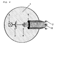
- the schematic structure of this spectrometer 1 is in FIG. 4 shown.
- the spectrometer 1 consists of a tunable laser 2 (eg DFB laser) whose wavelengths can be tuned very precisely and narrowband ( ⁇ 0.5 pm). Subsequently, this monochromatic light is divided into several paths to realize the appropriate number of subjects can.
- the beams are formed at the optical outputs of the splitter 3 into beams, which then according to FIG. 1 be converted into an area-spanning network of rays.
- This network (consisting of several compartments, each of which consists of a plurality of individual beams) is then used to measure the corresponding spectral transmissions of the paths in order to finally obtain the spatially resolved concentration information through tomographic inversion.
- the splitter can also be provided not to use the splitter and to direct the beam directly to a rotating mirror, which is located in the vicinity of the spectrometer, so not at the outer edge of the distribution space. Furthermore, it can be provided to separate the beam outside the spectrometer with a beam splitter or splitter into a plurality of sub-beams, in which case each sub-beam can be guided in turn onto a rotating mirror arranged in the vicinity of the spectrometer.
- the device according to the invention and the prior art method differ, above all, in the novel beam guidance concept, which allows tomography on the field scale.
- the use of such a system according to the invention for pedological questions is new.
- An essential advantage of the device according to the invention is that it is possible with only one Transmitter / detector unit to capture a large area with a large tomographic coverage.
- the spatial distribution of the concentration of atmospheric gases near the ground can be determined very precisely.
- the device according to the invention and the method according to the invention can thus be used for spatially resolved molecular spectroscopy on the field scale. Because of the per se relatively short measurement time of the open-path measurements and the ability to set the rotating mirror in short time intervals quickly and accurately, it is also possible according to the invention to perform spatially and time-resolved measurements on the field scale.
Landscapes
- Physics & Mathematics (AREA)
- Spectroscopy & Molecular Physics (AREA)
- Health & Medical Sciences (AREA)
- Life Sciences & Earth Sciences (AREA)
- Chemical & Material Sciences (AREA)
- Analytical Chemistry (AREA)
- Biochemistry (AREA)
- General Health & Medical Sciences (AREA)
- General Physics & Mathematics (AREA)
- Immunology (AREA)
- Pathology (AREA)
- Investigating Or Analysing Materials By Optical Means (AREA)
Applications Claiming Priority (1)
| Application Number | Priority Date | Filing Date | Title |
|---|---|---|---|
| DE102011005946 | 2011-03-23 |
Publications (2)
| Publication Number | Publication Date |
|---|---|
| EP2503323A2 true EP2503323A2 (fr) | 2012-09-26 |
| EP2503323A3 EP2503323A3 (fr) | 2012-12-19 |
Family
ID=46000718
Family Applications (1)
| Application Number | Title | Priority Date | Filing Date |
|---|---|---|---|
| EP12161125A Withdrawn EP2503323A3 (fr) | 2011-03-23 | 2012-03-23 | Dispositif et procédé de mesure de la répartition spatiale de gaz atmosphériques à proximité du sol |
Country Status (1)
| Country | Link |
|---|---|
| EP (1) | EP2503323A3 (fr) |
Cited By (6)
| Publication number | Priority date | Publication date | Assignee | Title |
|---|---|---|---|---|
| DE102012006047B3 (de) * | 2012-03-27 | 2013-08-01 | Deutsches Zentrum Für Luft- Und Raumfahrt | Vorrichtung zur Ermittlung von Gaskonzentrationen |
| WO2014063078A1 (fr) | 2012-10-19 | 2014-04-24 | Picarro, Inc. | Procédés permettant la détection et la localisation d'une fuite de gaz dans des zones habitées à l'aide de mesures de rapports isotopiques |
| US9482591B2 (en) | 2011-10-20 | 2016-11-01 | Picarro, Inc. | Methods for gas leak detection and localization in populated areas using horizontal analysis |
| US9500556B2 (en) | 2011-10-20 | 2016-11-22 | Picarro, Inc. | Methods for gas leak detection and localization in populated areas using multi-point analysis |
| US9739758B2 (en) | 2011-10-20 | 2017-08-22 | Picarro, Inc. | Methods for gas leak detection and localization in populated areas using isotope ratio measurements |
| US10113997B2 (en) | 2011-10-20 | 2018-10-30 | Picarro, Inc. | Methods for gas leak detection and localization in populated areas using two or more tracer measurements |
Citations (3)
| Publication number | Priority date | Publication date | Assignee | Title |
|---|---|---|---|---|
| AT2354B (fr) | 1899-06-05 | 1900-10-10 | Kahle Fa R | |
| US3925666A (en) | 1973-11-14 | 1975-12-09 | Ca Atomic Energy Ltd | Gas detection system |
| GB2274163A (en) | 1993-01-12 | 1994-07-13 | Pollution Monitor Syst Ltd | Gas analyser |
-
2012
- 2012-03-23 EP EP12161125A patent/EP2503323A3/fr not_active Withdrawn
Patent Citations (3)
| Publication number | Priority date | Publication date | Assignee | Title |
|---|---|---|---|---|
| AT2354B (fr) | 1899-06-05 | 1900-10-10 | Kahle Fa R | |
| US3925666A (en) | 1973-11-14 | 1975-12-09 | Ca Atomic Energy Ltd | Gas detection system |
| GB2274163A (en) | 1993-01-12 | 1994-07-13 | Pollution Monitor Syst Ltd | Gas analyser |
Non-Patent Citations (3)
| Title |
|---|
| HARTL, A.: "Tomographic Reconstruction of 2-D Atmospheric Trace Gas Distributions from Active DOAS Measurements", THESIS, 2007 |
| KASYUTICH, V. L.; MARTIN, P. A.: "Towards a two-dimensional concentration and temperature laser absorpti on tomography sensor system", APPLIED PHYSICS B: LASERS AND OPTICS, vol. 1, no. 14, 2010 |
| WANG, F.; K. F. CEN ET AL.: "Two-dimensional tomography for gas concentration and temperature distributions based on tunable diode laser absorption spectroscopy", MEASUREMENT SCIENCE AND TECHNOLOGY, vol. 21, 2010, XP020174482 |
Cited By (8)
| Publication number | Priority date | Publication date | Assignee | Title |
|---|---|---|---|---|
| US9482591B2 (en) | 2011-10-20 | 2016-11-01 | Picarro, Inc. | Methods for gas leak detection and localization in populated areas using horizontal analysis |
| US9500556B2 (en) | 2011-10-20 | 2016-11-22 | Picarro, Inc. | Methods for gas leak detection and localization in populated areas using multi-point analysis |
| US9739758B2 (en) | 2011-10-20 | 2017-08-22 | Picarro, Inc. | Methods for gas leak detection and localization in populated areas using isotope ratio measurements |
| US10113997B2 (en) | 2011-10-20 | 2018-10-30 | Picarro, Inc. | Methods for gas leak detection and localization in populated areas using two or more tracer measurements |
| DE102012006047B3 (de) * | 2012-03-27 | 2013-08-01 | Deutsches Zentrum Für Luft- Und Raumfahrt | Vorrichtung zur Ermittlung von Gaskonzentrationen |
| US9201007B2 (en) | 2012-03-27 | 2015-12-01 | Infineon Technologies Ag | Device for determination of gas concentration |
| WO2014063078A1 (fr) | 2012-10-19 | 2014-04-24 | Picarro, Inc. | Procédés permettant la détection et la localisation d'une fuite de gaz dans des zones habitées à l'aide de mesures de rapports isotopiques |
| EP2909597A4 (fr) * | 2012-10-19 | 2016-06-22 | Picarro Inc | Procédés permettant la détection et la localisation d'une fuite de gaz dans des zones habitées à l'aide de mesures de rapports isotopiques |
Also Published As
| Publication number | Publication date |
|---|---|
| EP2503323A3 (fr) | 2012-12-19 |
Similar Documents
| Publication | Publication Date | Title |
|---|---|---|
| EP2503323A2 (fr) | Dispositif et procédé de mesure de la répartition spatiale de gaz atmosphériques à proximité du sol | |
| DE112012001926B4 (de) | Verfahren und Vorrichtung zur Detektion einer verborgenen gefährlichen Substanz | |
| DE2452685C3 (de) | Anordnung zur Überwachung eines Raumbereichs auf die Anwesenheit eines Gases | |
| DE102014002514B4 (de) | Vorrichtung und Verfahren zur multi- oder hyperspektralen Bildgebung und / oder zur Distanz- und / oder 2-D oder 3-D Profilmessung eines Objekts mittels Spektrometrie | |
| DE3006421C2 (de) | Analysegerät zum Bestimmen eines besonderen Bestandteils in einer Probe | |
| DE102007056345B3 (de) | Verfahren zum Betrieb eines FTIR-Spektrometers, sowie FTIR-Spektrometer selbst | |
| EP3633405A1 (fr) | Appareil de mesure pour balayage 3d géométrique d'un environnement comportant une pluralité de canaux d'émission et de capteurs photomultiplicateur à semi-conducteurs | |
| EP2853869B1 (fr) | Procédé et analyseur de gaz pour la mesure de la concentration d'un composant de gaz dans un gaz de mesure | |
| DE2153315A1 (de) | Verfahren zur interferenzspektroskopischen Spektraluntersuchung einer Probe und Interferenz-Spektroskopiegerät zur Durchführung dieses Verfahrens | |
| DE102013010611A1 (de) | Messvorrichtung und Messverfahren zum Messen von Rohdaten zur Bestimmung eines Blutparameters, insbesondere zur nichtinvasiven Bestimmung der D-Glucose-Konzentration | |
| DE202012002375U1 (de) | Vorrichtung zur optischen Kohärenztomographie | |
| EP4254020A2 (fr) | Système et procédé de surveillance d'un espace d'air pour un site étendu | |
| DE2702332C3 (de) | Verfahren zur chemischen und mineralogischen Analyse des Erdbodens | |
| DE602005002348T2 (de) | Verfahren zur messung von teilcheneigenschaften mittels interferenzstreifenanalyse und entsprechende vorrichtung | |
| DE102012004977B3 (de) | Vorrichtung und Verfahren zum Messen eines Zielgases | |
| WO2015128393A1 (fr) | Procédé, optique, dispositif de mesure et système de mesure pour la spectroscopie térahertz à résolution locale dans le domaine temporel | |
| EP4061114A1 (fr) | Procédé pour déterminer et optimiser la teneur en au moins une composante végétale d'au moins une partie d'une plante | |
| DE102014101302B3 (de) | Verfahren zur Spektrometrie und Spektrometer | |
| EP3598103A1 (fr) | Analyseur de gaz et procédé d'analyse de gaz | |
| WO2018138138A1 (fr) | Procédé et dispositif de détection de structure superficielle et d'état d'un échantillon | |
| EP2912420A1 (fr) | Procédé et installation notamment pour la spectroscopie à transformée de fourier en application mobile | |
| DE2653465A1 (de) | Verfahren und vorrichtung fuer computer-tomographie | |
| DE102008003282B4 (de) | Anordnung und Verfahren zu einer Bestimmung einer Position zweier Objekte relativ zueinander | |
| DE102019203562A1 (de) | Verfahren zur Ermittlung einer Korrekturgrößenfunktion und Verfahren zur Erzeugung eines frequenzkorrigierten Hyperspektralbildes | |
| EP3792606A1 (fr) | Procédé et dispositif de spectroscopie non linéaire sur un échantillon |
Legal Events
| Date | Code | Title | Description |
|---|---|---|---|
| PUAI | Public reference made under article 153(3) epc to a published international application that has entered the european phase |
Free format text: ORIGINAL CODE: 0009012 |
|
| AK | Designated contracting states |
Kind code of ref document: A2 Designated state(s): AL AT BE BG CH CY CZ DE DK EE ES FI FR GB GR HR HU IE IS IT LI LT LU LV MC MK MT NL NO PL PT RO RS SE SI SK SM TR |
|
| AX | Request for extension of the european patent |
Extension state: BA ME |
|
| PUAL | Search report despatched |
Free format text: ORIGINAL CODE: 0009013 |
|
| AK | Designated contracting states |
Kind code of ref document: A3 Designated state(s): AL AT BE BG CH CY CZ DE DK EE ES FI FR GB GR HR HU IE IS IT LI LT LU LV MC MK MT NL NO PL PT RO RS SE SI SK SM TR |
|
| AX | Request for extension of the european patent |
Extension state: BA ME |
|
| RIC1 | Information provided on ipc code assigned before grant |
Ipc: G01N 21/35 20060101AFI20121113BHEP |
|
| 17P | Request for examination filed |
Effective date: 20130619 |
|
| RBV | Designated contracting states (corrected) |
Designated state(s): AL AT BE BG CH CY CZ DE DK EE ES FI FR GB GR HR HU IE IS IT LI LT LU LV MC MK MT NL NO PL PT RO RS SE SI SK SM TR |
|
| STAA | Information on the status of an ep patent application or granted ep patent |
Free format text: STATUS: THE APPLICATION IS DEEMED TO BE WITHDRAWN |
|
| 18D | Application deemed to be withdrawn |
Effective date: 20161001 |