EP2503247B1 - A stove - Google Patents
A stove Download PDFInfo
- Publication number
- EP2503247B1 EP2503247B1 EP12152383.1A EP12152383A EP2503247B1 EP 2503247 B1 EP2503247 B1 EP 2503247B1 EP 12152383 A EP12152383 A EP 12152383A EP 2503247 B1 EP2503247 B1 EP 2503247B1
- Authority
- EP
- European Patent Office
- Prior art keywords
- valve
- stove
- valve closure
- stove according
- rod
- Prior art date
- Legal status (The legal status is an assumption and is not a legal conclusion. Google has not performed a legal analysis and makes no representation as to the accuracy of the status listed.)
- Not-in-force
Links
Images


Classifications
-
- F—MECHANICAL ENGINEERING; LIGHTING; HEATING; WEAPONS; BLASTING
- F24—HEATING; RANGES; VENTILATING
- F24B—DOMESTIC STOVES OR RANGES FOR SOLID FUELS; IMPLEMENTS FOR USE IN CONNECTION WITH STOVES OR RANGES
- F24B13/00—Details solely applicable to stoves or ranges burning solid fuels
- F24B13/002—Surrounds
-
- F—MECHANICAL ENGINEERING; LIGHTING; HEATING; WEAPONS; BLASTING
- F24—HEATING; RANGES; VENTILATING
- F24B—DOMESTIC STOVES OR RANGES FOR SOLID FUELS; IMPLEMENTS FOR USE IN CONNECTION WITH STOVES OR RANGES
- F24B5/00—Combustion-air or flue-gas circulation in or around stoves or ranges
- F24B5/02—Combustion-air or flue-gas circulation in or around stoves or ranges in or around stoves
- F24B5/021—Combustion-air or flue-gas circulation in or around stoves or ranges in or around stoves combustion-air circulation
- F24B5/026—Supply of primary and secondary air for combustion
-
- F—MECHANICAL ENGINEERING; LIGHTING; HEATING; WEAPONS; BLASTING
- F24—HEATING; RANGES; VENTILATING
- F24B—DOMESTIC STOVES OR RANGES FOR SOLID FUELS; IMPLEMENTS FOR USE IN CONNECTION WITH STOVES OR RANGES
- F24B5/00—Combustion-air or flue-gas circulation in or around stoves or ranges
- F24B5/02—Combustion-air or flue-gas circulation in or around stoves or ranges in or around stoves
- F24B5/021—Combustion-air or flue-gas circulation in or around stoves or ranges in or around stoves combustion-air circulation
- F24B5/023—Supply of primary air for combustion
-
- F—MECHANICAL ENGINEERING; LIGHTING; HEATING; WEAPONS; BLASTING
- F23—COMBUSTION APPARATUS; COMBUSTION PROCESSES
- F23L—SUPPLYING AIR OR NON-COMBUSTIBLE LIQUIDS OR GASES TO COMBUSTION APPARATUS IN GENERAL ; VALVES OR DAMPERS SPECIALLY ADAPTED FOR CONTROLLING AIR SUPPLY OR DRAUGHT IN COMBUSTION APPARATUS; INDUCING DRAUGHT IN COMBUSTION APPARATUS; TOPS FOR CHIMNEYS OR VENTILATING SHAFTS; TERMINALS FOR FLUES
- F23L13/00—Construction of valves or dampers for controlling air supply or draught
- F23L13/02—Construction of valves or dampers for controlling air supply or draught pivoted about a single axis but having not other movement
-
- F—MECHANICAL ENGINEERING; LIGHTING; HEATING; WEAPONS; BLASTING
- F24—HEATING; RANGES; VENTILATING
- F24B—DOMESTIC STOVES OR RANGES FOR SOLID FUELS; IMPLEMENTS FOR USE IN CONNECTION WITH STOVES OR RANGES
- F24B1/00—Stoves or ranges
- F24B1/02—Closed stoves
- F24B1/028—Closed stoves with means for regulating combustion
Definitions
- the present invention relates to a stove, and in particular to an inset stove for burning solid fuel such as logs.
- inset stove As it is received in an opening in a wall so that its front fascia lies flush with or protrudes only by a small distance from the surface of the wall in which the inset stove is received.
- Stoves of this type include a combustion chamber or firebox in which fuel such as logs is received.
- a door provides access to the firebox, which has a flue outlet through which smoke and other combustion products are exhausted to the outside of the stove, typically through a flue provided in the building in which the stove is installed.
- the stove is provided with vents or air inlets through which external air can be introduced into the firebox to control the rate of combustion of the fuel.
- vents are provided towards a front surface of the stove and have a slotted grill, behind which a damper plate is slideably mounted.
- a lever is attached to the damper plate to allow the damper plate to be moved to cover or partially cover the slots in the grill, thereby preventing or restricting airflow through the slots of the grill into the firebox.
- Vents of this type can be difficult to operate accurately, because of the difficulty in manually moving the damper plate to a precise position in which a desired airflow is achieved. Moreover, as it can be difficult to achieve repeatedly a particular airflow setting because of the difficulty in manually moving the damper to exactly the same position as it has previously occupied, repeatability is a problem in stoves with vents of this type. Additionally, the lever which controls the damper plate typically projects outwardly of a front fascia of the stove, which can be unsightly and can therefore have a negative aesthetic effect on the stove, particular where the stove is an inset stove which is designed to have a substantially flat fascia.
- US 2005/194002 discloses an air bypass system for use with a heating appliance that includes an outer enclosure and a combustion chamber enclosure positioned within the outer enclosure.
- the bypass system includes a first opening providing an air passage between a source of air from a remote location and an air space defined between the outer enclosure and the combustion chamber enclosure.
- the bypass system also includes a second opening providing an air passage between a source of room air and the air space, and an actuating member configured for movement between a first position substantially covering the first opening wherein the second opening is open for air flow, and a second position substantially covering the second opening wherein the first opening is open for air flow.
- US 4313418 discloses a damper control system wherein a control screw is threadedly mounted in a door and engages a depending contact arm on a damper to move the damper between a closed position and various open positions.
- DE 202008004505 relates to a wood burning stove with a combustion chamber surrounded by a number of walls, at least one of which comprises a door with a viewing window.
- EP 1411299 discloses a fireplace comprising several access points, a closable combustion chamber, and at least one window unit with multiple glazing.
- WO2010/108111 discloses a fireplace assembly with an integrated burn control which may be used in combination with gas-burning fireplaces, stoves, and fireplace inserts.
- the fireplace assembly includes: a control panel; a concealment door that conceals the control panel when the concealment door is closed; automatic control panel lighting that is activated when the concealment door is open; a split flow or dual burner assembly that simulates a natural wood burning fire; and an intermittent pilot ignition system that allows a pilot flame to run continuously or intermittently.
- the present invention provides a stove according to the appended claims.
- rotary control means in the stove of the present invention permits greater precision and repeatability in positioning the valve gasket than in prior art stoves, as the rotary control means can easily be set to a previously used setting in which the valve gasket is positioned to achieve a desired airflow, whilst the recessed position of the rotary control means with respect to the fascia, and the concealing means allow the rotary control means to be concealed to add to the aesthetic appeal of the stove.
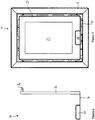
- a stove is shown generally at 10.
- the stove shown in Figure 1 is an inset stove which is intended to be received in an opening in a wall of a building such as a domestic dwelling.
- the stove 10 has a frame 12, a rear side of which abuts the wall around the opening when the stove 10 is installed, such that a front face of the frame 12 faces away from the wall.
- the frame 12 is attached to a stove body 14 which extends rearwardly of the frame 12 and, when the stove 10 is installed, is received in the opening in the wall.
- a door 16 is attached to the stove body 14 by means of a hinge 18, and opens to permit access to an interior of the stove 10.
- the door 16 in this example takes the form of a frame 20 of a metallic material that surrounds a panel 22 of tempered glass or another heat resistant material to permit visual access to the interior of the stove 10.
- the frame 20 of the door 16 is provided with a cut-out section 24 to accommodate rotary control knobs 26 of a valve assembly of the stove 10, which are positioned so as to be recessed with respect to a fascia of the stove 10 (which in this example is provided by the door 16) so that when the they can be concealed to provide a substantially flat fascia to add to the aesthetic appeal of the stove 10.
- the door 16 includes latching means to secure it in its closed position.
- the latching means 30 in this example comprises a rod 32 which is rotatably mounted at the opposite side of the door 16 to the hinge 18.
- the rod 32 includes a latch formation in the form of a hook 34 which extends outwardly of the rod and is configured to engage with a complementary receiving formation in a part of the stove 10 such as the frame 12 or body 14 of the stove 10 that is positioned adjacent the rod 32 when the door 16 is closed, to latch the door 16 in its closed position.
- a lower end of the rod 32 is received in a sleeve from which a lever 36 extends, in a direction generally opposed to the direction of the latch formation 34.
- the lever 36 When the door 16 is closed, the lever 36 extends laterally of the rod 32 beneath the frame 20 of the door, such that the lever does not protrude outwardly beyond the pane of the frame 20 of the door 16..
- the lever 36 terminates in a panel 38 which, when the door 16 is closed, is received in the cut-out section 24 of the frame 20 and lies substantially flush with the frame 20 of the door 16 to conceal the rotary control knobs 26 of the stove 10.
- a rear side of the panel 38 is provided with a tab which can be received by a spring latch provided in this example at a position intermediate the rotary control knobs 26, but which may be provided on the frame 20 of the door 16 or in any appropriate position on the stove body 14, to hold the panel 38 in position and thus prevent movement of the lever 32 and opening of the door 16.
- FIG 3 shows the stove 10 with the door 16 closed, from which it can be seen that when the door is closed the panel 38 conceals the rotary control knobs 26. In this way, with the door 16 closed the stove 10 has a substantially flat fascia..
- the panel 38 is depressed to release the spring latch, permitting movement of the panel 38 and lever 36.
- the lever 36 is then pivoted outwardly of the frame 12 of the stove 10.
- the lever 36 is free to rotate through a predefined angle without causing the rod 32 to rotate, to permit access to the rotary control knobs 26 without releasing the latch formation 34 from its engagement with the complementary receiving formation.
- the angle is approximately 60 degrees, as this causes the lever 36 and the panel 38 to move sufficiently far from frame 12 of the stove to allows adequate room for the rotary control knobs 26 to be accessed. It will be appreciated that any angle of rotation that achieves this could equally be employed.
- FIG. 4 is a schematic cross-sectional view taken from one side of the stove 10. As can be seen from Figure 4 , the stove 10 includes a combustion chamber or firebox 40, which is positioned so as to be visible though the panel 22 of the door 16 when the door 16 is closed.
- a flue outlet 42 is provided in an upper part of the firebox 40 to allow smoke and other combustion products to be exhausted to an exterior of the stove 10, typically through a flue provided in the building in which the stove is installed.
- a rear wall 44 of the firebox 40 is provided, towards an upper part, with a first air inlet 46, and towards a lower part with a second air inlet 48.
- the first air inlet 46 communicates with a first conduit 50 which receives air from an exterior of the stove 10, whilst the second air inlet 48 communicates with a second conduit 52 which receives air from the exterior of the stove 10.
- the first conduit 50 contains a first valve which is controlled by one of the rotary control knobs 26, and the second conduit 52 contains a second valve which is controlled by the other of the rotary control knobs 26, as is described in detail below.
- the stove 10 includes a valve assembly 60 which controls airflow to the first and second air inlets 46, 48 of the firebox 40.
- the valve assembly is provided as a removable cartridge 62 which slots into the stove body 14 beneath the firebox 40, as shown in Figure 4 . This arrangement is advantageous as it facilitates servicing or replacement of the valve assembly 60, as the cartridge 62 can simply be slid out of the stove body 14 without disassembling the stove 10.
- FIG. 5 is a schematic perspective representation of the valve assembly 60.
- the valve assembly includes a control fascia 64 on which the rotary control knobs 26 are mounted.
- the control fascia 64 is connected to a valve frame 66 in which first and second valve closures 68, 70 are received.
- the first and second valve closures 68, 70 each have a valve gasket 72 which securely seals an aperture in the first or second conduit 50, 52 when the valve closures 68, 70 are raised to a position in which they are fully engaged with the aperture, to close the aperture and prevent air flow to the first and second air inlets 46, 48.
- FIG. 6 The exploded perspective view of Figure 6 shows the arrangement linking one of the rotary control knobs 26 to the first valve closure 68, but it is to be appreciated that the arrangement linking the other control knob 26 to the second valve closure 70 is identical in its construction and operation, but is a mirror image of the arrangement shown in Figure 6 , as can be seen from Figure 5 .
- the rotary control knob 26 is mounted on a threaded control screw 74 which passes through an aperture in the control fascia 64 and a co-axial threaded aperture in a thread block 76 which is disposed immediately behind the control fascia 64.
- the control knob 26 is secured to the control screw 74 by means of a grub screw 78.
- a compression spring 80 is mounted on the control screw 74 and abuts at one end against a washer 82 which is retained by a pin 83 which passes through the control screw 74 and at the other end against the thread block 76 to bias the control screw 74 towards an extended position.
- the thread of the aperture in the thread block 76 is complementary to the thread of the control screw 74 such that when the control screw 74 is rotated by anti-clockwise rotation of the control knob 26 a free distal end 84 of the control screw 74 extends linearly away from the thread block 76, and when the control screw 74 is rotated in a clockwise direction the free distal end 84 of the control screw 74 retracts linearly towards the thread block 76.
- the inter-engagement of the threads of the control screw 74 and the aperture of the thread block 76 also acts to hold the control screw 74, and thus the control knob 26, in position when rotation of the control knob 26 ceases.
- the valve frame 66 has two side plates 94 which are substantially parallel to each other and which have attachment lugs 96 that are substantially perpendicular to the side plates 92 such that when the side plates 94 are attached to the front plate 92 by means of the attachment lugs 96 the side plates 94 are substantially perpendicular to the front plate 94.
- the valve frame 66 also has a floor plate 97 which extends between the side plates 94.
- a tongue 98 extends outwardly of a rear edge of the floor plate 97.
- the tongue 98 is resiliently biased in a downward direction and, when the valve assembly 60 is received in the stove 10, engages with a base plate of the stove to urge the top of the valve frame 66 towards a plate in which air inlets of the conduits 50, 52 are provided, to hold the valve frame 66 securely in the correct position with respect to the air inlets of the conduits 50, 52.
- the tongue 98 also has a secondary effect of impeding movement of the valve assembly 60 with respect to the stove 10, but does not prevent removal of the valve assembly 60 from the stove if sufficient force is applied to pull the valve assembly 60 out of the stove 10.
- a first pair of mounting holes 100 are provided in a forward portion of each of the side plates 94 for receiving a substantially cylindrical bell crank shaft 102.
- the first mounting holes 100 of the side plates 94 are aligned, such that when the bell crank shaft 102 is received in the first mounting holes 100 its longitudinal axis is substantially parallel to the front plate 92 of the valve frame 66.
- a second pair of mounting holes 104 are provided in a rear portion of each of the side plates for receiving a substantially cylindrical valve shaft 106. The second holes are aligned such that when the valve shaft 106 is received in the second holes 106 its longitudinal axis is substantially parallel to the front plate 92 and the longitudinal axis of the bell crank shaft 102.
- a bell crank 108 is attached to an exterior surface of one end of hollow, generally cylindrical sleeve 110 which is rotatably mounted on the bell crank shaft 102, such that when the bell crank shaft 102 and the sleeve 110 are installed in the valve frame 60 the bell crank 108 is positioned adjacent one of the side plates 94 and can rotate about the bell crank shaft 102.
- the bell crank 108 has a generally flat first arm 111 which acts as an engagement portion.
- a hole or recess is provided in the first arm 111 to retain a distal end of the push rod 88.
- One side of a free end of the first arm 111 is attached to the exterior surface of the end of the sleeve 110.
- a second arm 112 extends outwardly of the first arm 111 in a direction generally perpendicular to the first arm 111, such that in normal use of the valve assembly 60 the second arm 112 extends towards a rear of the valve assembly 60.
- a distal end portion 114 of the second arm 112 is angled upwardly with respect to the second arm 112, and a generally cylindrical rod 116 is mounted on the distal end portion 114 of the second arm 112 extending in a direction generally perpendicular to the second arm 112 such that a longitudinal axis of the rod 116 is substantially parallel to those of the bell crank shaft 102 and the valve shaft 106.
- the first valve closure 68 has first and second side plates 118 which are disposed in a substantially parallel spaced configuration, being linked together by a top plate 120.
- the first and second side plates 118 are each provided with a notch 122 in a front portion of the first and second side plates 118, and when the first valve closure 68 is assembled these notches 122 are aligned such that the first valve closure 68 can be rotatably mounted on the valve shaft 106 by receiving the valve shaft 106 in the aligned notches 122.
- a valve weight 124 is attached to an underside of the top plate 120 at a position intermediate the notches 122 and a rear edge 126 of the top plate 120, and the valve gasket 72 is provided on an upper surface of the top plate 120.
- the first valve closure 68 When the valve assembly 60 is assembled, the first valve closure 68 is mounted on the valve shaft 106, and the valve weight 124 causes the valve closure 68 to rotate in a clockwise direction until the underside of the top plate 120 abuts against the rod 116. Thus, in normal operation of the valve assembly the first valve closure 68 is supported by the valve shaft 106 and by the rod 116.
- valve assembly 60 is cross-sectional views of the valve assembly 60 with the valves in different positions corresponding to different airflow settings.
- Figure 7 shows the valve assembly 60 with the first valve closure 68 in a fully open position. In this position the valve closure 68 rests on a stop 130 of the valve assembly 60.
- Rotation of the control knob 26 in an anti-clockwise direction causes the control screw 74 to move towards the valve closure 68, which in turn causes the push rod 88 to extend.
- the distal end of the push rod 88 which abuts against the first arm 111 of the bell crank 108, causes the bell crank 108 to rotate about the bell crank shaft 102.
- the second arm 112 of the bell crank 108 therefore rotates in an anti-clockwise direction, as shown by the arrow 132 of Figure 8 , and the magnitude of the rotation of the second arm 112 is much larger than the magnitude of the movement of the push rod 88, i.e. the bell crank 108 amplifies the motion of the push rod 88.
- the rod 116 mounted on the distal end portion of the second arm 112 moves with the second arm 112, and as the underside of the top plate 120 of the valve closure 68 abuts against the rod 116, this causes the valve closure 68 to be raised by pivoting around the valve shaft 106.
- the position of the valve weight 124 intermediate the notches 122 and the rear edge 126 of the top plate 120 ensures that the rear edge 126 of the top plate 120 is lifted before the front edge of the top plate 120. This has advantageous effects, which are described below.
- the rotation of the control knob is limited by a first pin 136 which passes through the control screw 74 and interacts with a second pin 138 which extends rearwardly of the thread block 76.
- the first pin 138 acts as a stop to limit rotation of the control screw 74 in either direction.
- the length and position of the first and second pins 136, 138 are selected so that the degree of rotation permitted by the interacting first and second pins 136, 138 ensures that the valve closure 68 has sufficient travel to become fully seated (closed) and fully open with sufficient tolerance to accommodate slight variations in stove dimensions.
Description
- The present invention relates to a stove, and in particular to an inset stove for burning solid fuel such as logs.
- Stoves which burn solid fuel such as logs have long been popular for use in domestic dwellings because of their heating and aesthetic qualities. One common type of solid fuel burning stove is known as an inset stove, as it is received in an opening in a wall so that its front fascia lies flush with or protrudes only by a small distance from the surface of the wall in which the inset stove is received.
- Stoves of this type include a combustion chamber or firebox in which fuel such as logs is received. A door provides access to the firebox, which has a flue outlet through which smoke and other combustion products are exhausted to the outside of the stove, typically through a flue provided in the building in which the stove is installed.
- The stove is provided with vents or air inlets through which external air can be introduced into the firebox to control the rate of combustion of the fuel. Typically these vents are provided towards a front surface of the stove and have a slotted grill, behind which a damper plate is slideably mounted. A lever is attached to the damper plate to allow the damper plate to be moved to cover or partially cover the slots in the grill, thereby preventing or restricting airflow through the slots of the grill into the firebox.
- Vents of this type can be difficult to operate accurately, because of the difficulty in manually moving the damper plate to a precise position in which a desired airflow is achieved. Moreover, as it can be difficult to achieve repeatedly a particular airflow setting because of the difficulty in manually moving the damper to exactly the same position as it has previously occupied, repeatability is a problem in stoves with vents of this type. Additionally, the lever which controls the damper plate typically projects outwardly of a front fascia of the stove, which can be unsightly and can therefore have a negative aesthetic effect on the stove, particular where the stove is an inset stove which is designed to have a substantially flat fascia.
-
US 2005/194002 discloses an air bypass system for use with a heating appliance that includes an outer enclosure and a combustion chamber enclosure positioned within the outer enclosure. The bypass system includes a first opening providing an air passage between a source of air from a remote location and an air space defined between the outer enclosure and the combustion chamber enclosure. The bypass system also includes a second opening providing an air passage between a source of room air and the air space, and an actuating member configured for movement between a first position substantially covering the first opening wherein the second opening is open for air flow, and a second position substantially covering the second opening wherein the first opening is open for air flow. -
US 4313418 discloses a damper control system wherein a control screw is threadedly mounted in a door and engages a depending contact arm on a damper to move the damper between a closed position and various open positions. -
DE 202008004505 relates to a wood burning stove with a combustion chamber surrounded by a number of walls, at least one of which comprises a door with a viewing window. -
EP 1411299 discloses a fireplace comprising several access points, a closable combustion chamber, and at least one window unit with multiple glazing. -
WO2010/108111 discloses a fireplace assembly with an integrated burn control which may be used in combination with gas-burning fireplaces, stoves, and fireplace inserts. - The fireplace assembly includes: a control panel; a concealment door that conceals the control panel when the concealment door is closed; automatic control panel lighting that is activated when the concealment door is open; a split flow or dual burner assembly that simulates a natural wood burning fire; and an intermittent pilot ignition system that allows a pilot flame to run continuously or intermittently.
- The present invention provides a stove according to the appended claims.
- The use of rotary control means in the stove of the present invention permits greater precision and repeatability in positioning the valve gasket than in prior art stoves, as the rotary control means can easily be set to a previously used setting in which the valve gasket is positioned to achieve a desired airflow, whilst the recessed position of the rotary control means with respect to the fascia, and the concealing means allow the rotary control means to be concealed to add to the aesthetic appeal of the stove.
- Embodiments of the invention will now be described, strictly by way of example only, with reference to the accompanying drawings, of which:
-
Figure 1 is a perspective view of a stove according to an embodiment of the present invention; -
Figure 2 is a schematic representation of a latch mechanism for latching a door of the stove ofFigure 1 in a closed position. -
Figure 3 is a view of the front of the stove ofFigure 1 ; -
Figure 4 is a schematic cross-sectional view taken from one side of the stove ofFigure 1 ; -
Figure 5 is a schematic perspective representation of a valve assembly used in the stove ofFigures 1 and3 ; -
Figure 6 is an exploded perspective view of the valve assembly shown inFigure 5 ; and. -
Figures 7 to 10 are schematic cross-sectional views of the valve assembly shown inFigures 5 and6 , illustrating the operation of the valve assembly. - Referring first to
Figure 1 , a stove is shown generally at 10. The stove shown inFigure 1 is an inset stove which is intended to be received in an opening in a wall of a building such as a domestic dwelling. Thestove 10 has aframe 12, a rear side of which abuts the wall around the opening when thestove 10 is installed, such that a front face of theframe 12 faces away from the wall. - The
frame 12 is attached to astove body 14 which extends rearwardly of theframe 12 and, when thestove 10 is installed, is received in the opening in the wall. Adoor 16 is attached to thestove body 14 by means of a hinge 18, and opens to permit access to an interior of thestove 10. Thedoor 16 in this example takes the form of aframe 20 of a metallic material that surrounds apanel 22 of tempered glass or another heat resistant material to permit visual access to the interior of thestove 10. Theframe 20 of thedoor 16 is provided with a cut-outsection 24 to accommodaterotary control knobs 26 of a valve assembly of thestove 10, which are positioned so as to be recessed with respect to a fascia of the stove 10 (which in this example is provided by the door 16) so that when the they can be concealed to provide a substantially flat fascia to add to the aesthetic appeal of thestove 10. - The
door 16 includes latching means to secure it in its closed position. As shown inFigure 2 , the latching means 30 in this example comprises arod 32 which is rotatably mounted at the opposite side of thedoor 16 to the hinge 18. Therod 32 includes a latch formation in the form of ahook 34 which extends outwardly of the rod and is configured to engage with a complementary receiving formation in a part of thestove 10 such as theframe 12 orbody 14 of thestove 10 that is positioned adjacent therod 32 when thedoor 16 is closed, to latch thedoor 16 in its closed position. A lower end of therod 32 is received in a sleeve from which alever 36 extends, in a direction generally opposed to the direction of thelatch formation 34. When thedoor 16 is closed, thelever 36 extends laterally of therod 32 beneath theframe 20 of the door, such that the lever does not protrude outwardly beyond the pane of theframe 20 of thedoor 16.. Thelever 36 terminates in apanel 38 which, when thedoor 16 is closed, is received in the cut-outsection 24 of theframe 20 and lies substantially flush with theframe 20 of thedoor 16 to conceal therotary control knobs 26 of thestove 10. A rear side of thepanel 38 is provided with a tab which can be received by a spring latch provided in this example at a position intermediate therotary control knobs 26, but which may be provided on theframe 20 of thedoor 16 or in any appropriate position on thestove body 14, to hold thepanel 38 in position and thus prevent movement of thelever 32 and opening of thedoor 16. -
Figure 3 shows thestove 10 with thedoor 16 closed, from which it can be seen that when the door is closed thepanel 38 conceals therotary control knobs 26. In this way, with thedoor 16 closed thestove 10 has a substantially flat fascia.. - To open the
door 16, thepanel 38 is depressed to release the spring latch, permitting movement of thepanel 38 and lever 36. Thelever 36 is then pivoted outwardly of theframe 12 of thestove 10. Thelever 36 is free to rotate through a predefined angle without causing therod 32 to rotate, to permit access to therotary control knobs 26 without releasing thelatch formation 34 from its engagement with the complementary receiving formation. In this example the angle is approximately 60 degrees, as this causes thelever 36 and thepanel 38 to move sufficiently far fromframe 12 of the stove to allows adequate room for therotary control knobs 26 to be accessed. It will be appreciated that any angle of rotation that achieves this could equally be employed. - Once the
lever 36 has rotated through an angle greater than the predefined angle, for example through an angle greater than 60 degrees, the sleeve engages with therod 32, causing therod 32 to rotate, which in turns causes thelatch formation 34 to disengage from the complementary receiving formation. Once thelatch formation 34 has completely disengaged from the receiving formation thedoor 16 can be opened to permit access to the interior of thestove 10.
Figure 4 is a schematic cross-sectional view taken from one side of thestove 10. As can be seen fromFigure 4 , thestove 10 includes a combustion chamber orfirebox 40, which is positioned so as to be visible though thepanel 22 of thedoor 16 when thedoor 16 is closed. Aflue outlet 42 is provided in an upper part of thefirebox 40 to allow smoke and other combustion products to be exhausted to an exterior of thestove 10, typically through a flue provided in the building in which the stove is installed. A rear wall 44 of thefirebox 40 is provided, towards an upper part, with afirst air inlet 46, and towards a lower part with asecond air inlet 48. Thefirst air inlet 46 communicates with afirst conduit 50 which receives air from an exterior of thestove 10, whilst thesecond air inlet 48 communicates with asecond conduit 52 which receives air from the exterior of thestove 10. Thefirst conduit 50 contains a first valve which is controlled by one of therotary control knobs 26, and thesecond conduit 52 contains a second valve which is controlled by the other of therotary control knobs 26, as is described in detail below. - The
stove 10 includes avalve assembly 60 which controls airflow to the first andsecond air inlets firebox 40. The valve assembly is provided as a removable cartridge 62 which slots into thestove body 14 beneath thefirebox 40, as shown inFigure 4 . This arrangement is advantageous as it facilitates servicing or replacement of thevalve assembly 60, as the cartridge 62 can simply be slid out of thestove body 14 without disassembling thestove 10. -
Figure 5 is a schematic perspective representation of thevalve assembly 60. As can be seen fromFigure 5 , the valve assembly includes acontrol fascia 64 on which the rotary control knobs 26 are mounted. Thecontrol fascia 64 is connected to avalve frame 66 in which first andsecond valve closures second valve closures valve gasket 72 which securely seals an aperture in the first orsecond conduit valve closures second air inlets valve closures valve apertures second air inlets Figures 6 to 11 of the drawings. - The exploded perspective view of
Figure 6 shows the arrangement linking one of the rotary control knobs 26 to thefirst valve closure 68, but it is to be appreciated that the arrangement linking theother control knob 26 to thesecond valve closure 70 is identical in its construction and operation, but is a mirror image of the arrangement shown inFigure 6 , as can be seen fromFigure 5 . - As can be seen from
Figure 6 , therotary control knob 26 is mounted on a threadedcontrol screw 74 which passes through an aperture in thecontrol fascia 64 and a co-axial threaded aperture in athread block 76 which is disposed immediately behind thecontrol fascia 64. Thecontrol knob 26 is secured to thecontrol screw 74 by means of agrub screw 78. Acompression spring 80 is mounted on thecontrol screw 74 and abuts at one end against awasher 82 which is retained by apin 83 which passes through thecontrol screw 74 and at the other end against thethread block 76 to bias thecontrol screw 74 towards an extended position. - The thread of the aperture in the
thread block 76 is complementary to the thread of thecontrol screw 74 such that when thecontrol screw 74 is rotated by anti-clockwise rotation of the control knob 26 a free distal end 84 of thecontrol screw 74 extends linearly away from thethread block 76, and when thecontrol screw 74 is rotated in a clockwise direction the free distal end 84 of thecontrol screw 74 retracts linearly towards thethread block 76. The inter-engagement of the threads of thecontrol screw 74 and the aperture of thethread block 76 also acts to hold thecontrol screw 74, and thus thecontrol knob 26, in position when rotation of thecontrol knob 26 ceases. - The free distal end 84 of the control screw abuts against a
free end 86 of apush rod 88, which passes through anaperture 90 in afront plate 92 of thevalve frame 66. Thevalve frame 66 has twoside plates 94 which are substantially parallel to each other and which have attachment lugs 96 that are substantially perpendicular to theside plates 92 such that when theside plates 94 are attached to thefront plate 92 by means of the attachment lugs 96 theside plates 94 are substantially perpendicular to thefront plate 94. Thevalve frame 66 also has afloor plate 97 which extends between theside plates 94. Atongue 98 extends outwardly of a rear edge of thefloor plate 97. Thetongue 98 is resiliently biased in a downward direction and, when thevalve assembly 60 is received in thestove 10, engages with a base plate of the stove to urge the top of thevalve frame 66 towards a plate in which air inlets of theconduits valve frame 66 securely in the correct position with respect to the air inlets of theconduits tongue 98 also has a secondary effect of impeding movement of thevalve assembly 60 with respect to thestove 10, but does not prevent removal of thevalve assembly 60 from the stove if sufficient force is applied to pull thevalve assembly 60 out of thestove 10. - A first pair of mounting
holes 100 are provided in a forward portion of each of theside plates 94 for receiving a substantially cylindrical bell crankshaft 102. The first mountingholes 100 of theside plates 94 are aligned, such that when the bell crankshaft 102 is received in the first mountingholes 100 its longitudinal axis is substantially parallel to thefront plate 92 of thevalve frame 66. A second pair of mountingholes 104 are provided in a rear portion of each of the side plates for receiving a substantiallycylindrical valve shaft 106. The second holes are aligned such that when thevalve shaft 106 is received in thesecond holes 106 its longitudinal axis is substantially parallel to thefront plate 92 and the longitudinal axis of the bell crankshaft 102. - A
bell crank 108 is attached to an exterior surface of one end of hollow, generallycylindrical sleeve 110 which is rotatably mounted on the bell crankshaft 102, such that when the bell crankshaft 102 and thesleeve 110 are installed in thevalve frame 60 the bell crank 108 is positioned adjacent one of theside plates 94 and can rotate about the bell crankshaft 102. - The
bell crank 108 has a generally flat first arm 111 which acts as an engagement portion. A hole or recess is provided in the first arm 111 to retain a distal end of thepush rod 88. One side of a free end of the first arm 111 is attached to the exterior surface of the end of thesleeve 110. Asecond arm 112 extends outwardly of the first arm 111 in a direction generally perpendicular to the first arm 111, such that in normal use of thevalve assembly 60 thesecond arm 112 extends towards a rear of thevalve assembly 60. Adistal end portion 114 of thesecond arm 112 is angled upwardly with respect to thesecond arm 112, and a generally cylindrical rod 116 is mounted on thedistal end portion 114 of thesecond arm 112 extending in a direction generally perpendicular to thesecond arm 112 such that a longitudinal axis of the rod 116 is substantially parallel to those of the bell crankshaft 102 and thevalve shaft 106. - The
first valve closure 68 has first andsecond side plates 118 which are disposed in a substantially parallel spaced configuration, being linked together by atop plate 120. The first andsecond side plates 118 are each provided with anotch 122 in a front portion of the first andsecond side plates 118, and when thefirst valve closure 68 is assembled thesenotches 122 are aligned such that thefirst valve closure 68 can be rotatably mounted on thevalve shaft 106 by receiving thevalve shaft 106 in the alignednotches 122. Avalve weight 124 is attached to an underside of thetop plate 120 at a position intermediate thenotches 122 and arear edge 126 of thetop plate 120, and thevalve gasket 72 is provided on an upper surface of thetop plate 120. - When the
valve assembly 60 is assembled, thefirst valve closure 68 is mounted on thevalve shaft 106, and thevalve weight 124 causes thevalve closure 68 to rotate in a clockwise direction until the underside of thetop plate 120 abuts against the rod 116. Thus, in normal operation of the valve assembly thefirst valve closure 68 is supported by thevalve shaft 106 and by the rod 116. - The operation of the
valve assembly 60 will now be described with reference toFigures 7 to 10 of the drawings, which are cross-sectional views of thevalve assembly 60 with the valves in different positions corresponding to different airflow settings. -
Figure 7 shows thevalve assembly 60 with thefirst valve closure 68 in a fully open position. In this position thevalve closure 68 rests on astop 130 of thevalve assembly 60. - Rotation of the
control knob 26 in an anti-clockwise direction causes thecontrol screw 74 to move towards thevalve closure 68, which in turn causes thepush rod 88 to extend. The distal end of thepush rod 88, which abuts against the first arm 111 of the bell crank 108, causes the bell crank 108 to rotate about the bell crankshaft 102. Thesecond arm 112 of the bell crank 108 therefore rotates in an anti-clockwise direction, as shown by the arrow 132 ofFigure 8 , and the magnitude of the rotation of thesecond arm 112 is much larger than the magnitude of the movement of thepush rod 88, i.e. the bell crank 108 amplifies the motion of thepush rod 88. The rod 116 mounted on the distal end portion of thesecond arm 112 moves with thesecond arm 112, and as the underside of thetop plate 120 of thevalve closure 68 abuts against the rod 116, this causes thevalve closure 68 to be raised by pivoting around thevalve shaft 106. The position of thevalve weight 124 intermediate thenotches 122 and therear edge 126 of thetop plate 120 ensures that therear edge 126 of thetop plate 120 is lifted before the front edge of thetop plate 120. This has advantageous effects, which are described below. - When the
rear edge 126 of thetop plate 120 comes into contact with the area around the aperture in theconduit valve closure 68 around thevalve shaft 106 is no longer possible, and thevalve closure 68 begins to pivot around the point of contact between thetop plate 120 and the area around the aperture, as indicated by thearrow 134 ofFigure 9 , lifting the front edge of thetop plate 120. Further anti-clockwise motion of thecontrol knob 26 causes this motion to continue until thevalve closure 68 is fully seated and thevalve gasket 72 seals the aperture to close the valve and prevent airflow through the aperture, as shown inFigure 10 . - The rotation of the control knob is limited by a
first pin 136 which passes through thecontrol screw 74 and interacts with asecond pin 138 which extends rearwardly of thethread block 76. Thefirst pin 138 acts as a stop to limit rotation of thecontrol screw 74 in either direction. The length and position of the first andsecond pins second pins valve closure 68 has sufficient travel to become fully seated (closed) and fully open with sufficient tolerance to accommodate slight variations in stove dimensions.
Claims (14)
- A stove (10) comprising a combustion chamber (40) and a valve assembly (60) for regulating air flow into the combustion chamber (40), wherein the valve assembly (60) comprises a valve closure (68, 70) for closing a valve aperture of the stove and rotary control means (26) for raising the valve closure (68, 70) towards the valve aperture and lowering the valve closure (68, 70) away from the valve aperture, wherein the rotary control means (26) is positioned so as to be recessed with respect to a fascia of the stove (10), and in that the stove (10) further comprises concealing means (38) for concealing the rotary control means (26), characterised in that the stove further comprises:a door (16) of the stove (10) provided with a cut-out section (24) for accommodating the rotary control means (26); latching means for securing the door (16) in its closed position, the latching means comprising a rod (32) which is rotatably mounted in part of the door (16) and which has an engagement formation that is configured to engage with a complementary receiving formation provided in part of the stove which is positioned adjacent the rod when the door (16) is closed, the latching means further comprising a lever (36) which engages with the rod (32) and can be moved to cause rotation of the rod (32); and wherein the concealing means comprises a panel (38) provided on the lever (36), which panel (38) is configured to be received in the cut-out section (24) of the door (16).
- A stove according to claim 1 wherein the lever (36) is free to rotate through a predetermined angle without engaging with the rod (32) such that during rotation of the lever (36) through the predetermined angle the rod (32) does not rotate.
- A stove according to claim 2 wherein the predetermined angle is approximately 60 degrees.
- A stove according to claim 1 wherein the panel (38) is provided with latching means for holding the panel (38) in position and restraining movement of the lever (36).
- A stove according to any one of the preceding claims wherein the valve assembly (60) comprises a mechanical linkage which links the rotary control means (26) to the valve closure (68, 70).
- A stove according to claim 5 wherein the mechanical linkage comprises a control screw (74) which is fixed to the rotary control means (26) for rotary motion therewith, the control screw (74) having a free end which abuts against a free end of a push rod (88), the push rod (88) having a free distal end which engages with a first arm of a pivotally mounted bell crank (108) having a second arm which acts on the valve closure (68, 70) such that rotation of the rotary control means (26) causes pivotal motion of the bell crank (108) and hence movement of the valve closure (68, 70).
- A stove according to claim 5 wherein the valve closure (68, 70) is provided with aligned notches (122) in front portions of side plates of the valve closure (68, 70) by means of which the valve closure (68, 70) is mounted on a valve shaft (106) such that movement of the bell crank (108) causes pivotal movement of the valve closure (68, 70) around the valve shaft (106).
- A stove according to claim 7 wherein the valve closure (68, 70) is provided with a weight (124) which is positioned intermediate the notches (122) and a rear portion of the valve closure (68, 70).
- A stove according to claim 7 or claim 8 wherein a rod is mounted on a distal end of the second arm of the bell crank (108) for engagement with an underside of a top plate of the valve closure (68, 70) such that if pivotal motion of the valve closure (68, 70) around the valve shaft (106) is impeded by contact between the rear portion of the valve closure (68, 70) and an object, further movement of the bell crank (108) causes the valve closure (68, 70) to pivot about a point of contact between the rear portion of the valve closure (68, 70) and the object.
- A stove according to any one of the preceding claims wherein the valve closure (68, 70) is provided with a valve gasket (72).
- A stove according to any one of the preceding claims wherein the valve assembly comprises stop means for limiting the extent of rotation of the rotary control means (26).
- A stove according to claim 11 wherein the stop means comprises a first pin (136) which projects from a portion of the valve assembly for engagement with a second pin (138) which is associated with the rotary control means (26).
- A stove according to any one of the preceding claims wherein the valve assembly is provided with a resilient tongue for biasing the valve assembly towards a position in which the valve closure (68, 70) is correctly positioned with respect to valve apertures of the stove (10).
- A stove according to any one of the preceding claims wherein the valve assembly is provided as a removable cartridge (62).
Applications Claiming Priority (1)
| Application Number | Priority Date | Filing Date | Title |
|---|---|---|---|
| GB1104740.4A GB2489240B (en) | 2011-03-22 | 2011-03-22 | A stove |
Publications (3)
| Publication Number | Publication Date |
|---|---|
| EP2503247A2 EP2503247A2 (en) | 2012-09-26 |
| EP2503247A3 EP2503247A3 (en) | 2015-08-12 |
| EP2503247B1 true EP2503247B1 (en) | 2017-10-25 |
Family
ID=44012910
Family Applications (1)
| Application Number | Title | Priority Date | Filing Date |
|---|---|---|---|
| EP12152383.1A Not-in-force EP2503247B1 (en) | 2011-03-22 | 2012-01-25 | A stove |
Country Status (5)
| Country | Link |
|---|---|
| EP (1) | EP2503247B1 (en) |
| DK (1) | DK2503247T3 (en) |
| ES (1) | ES2654591T3 (en) |
| GB (1) | GB2489240B (en) |
| PT (1) | PT2503247T (en) |
Citations (1)
| Publication number | Priority date | Publication date | Assignee | Title |
|---|---|---|---|---|
| WO2010108111A1 (en) * | 2009-03-19 | 2010-09-23 | Travis Industries, Inc. | Fireplace assembly with integrated burn control system |
Family Cites Families (7)
| Publication number | Priority date | Publication date | Assignee | Title |
|---|---|---|---|---|
| US4313418A (en) * | 1980-03-18 | 1982-02-02 | Janice E. Schrader | Damper control |
| US4483312A (en) * | 1980-07-01 | 1984-11-20 | Martenson Donald S | Free standing stove |
| US4475529A (en) * | 1981-04-29 | 1984-10-09 | Milligan Orley J | Solid fuel burning stove with exterior rear wall baffle |
| GB2389414B (en) * | 2002-06-06 | 2005-09-28 | A J Wells & Sons | Stove |
| DE10248288A1 (en) * | 2002-10-16 | 2004-05-06 | Cera-Design By Britta Von Tasch Gmbh | Fireplace visible from several sides |
| CA2459913A1 (en) * | 2004-03-05 | 2005-09-05 | Hon Technology Inc. | Adjustable air bypass system for heating appliance |
| DE202008004505U1 (en) * | 2008-04-01 | 2008-07-31 | Leda-Werk Gmbh & Co. Kg Boekhoff & Co. | Stove for burning solids with at least one combustion chamber |
-
2011
- 2011-03-22 GB GB1104740.4A patent/GB2489240B/en not_active Expired - Fee Related
-
2012
- 2012-01-25 DK DK12152383.1T patent/DK2503247T3/en active
- 2012-01-25 PT PT121523831T patent/PT2503247T/en unknown
- 2012-01-25 EP EP12152383.1A patent/EP2503247B1/en not_active Not-in-force
- 2012-01-25 ES ES12152383.1T patent/ES2654591T3/en active Active
Patent Citations (1)
| Publication number | Priority date | Publication date | Assignee | Title |
|---|---|---|---|---|
| WO2010108111A1 (en) * | 2009-03-19 | 2010-09-23 | Travis Industries, Inc. | Fireplace assembly with integrated burn control system |
Also Published As
| Publication number | Publication date |
|---|---|
| DK2503247T3 (en) | 2018-01-08 |
| EP2503247A2 (en) | 2012-09-26 |
| GB201104740D0 (en) | 2011-05-04 |
| ES2654591T3 (en) | 2018-02-14 |
| GB2489240B (en) | 2016-06-15 |
| PT2503247T (en) | 2018-01-04 |
| GB2489240A (en) | 2012-09-26 |
| EP2503247A3 (en) | 2015-08-12 |
Similar Documents
| Publication | Publication Date | Title |
|---|---|---|
| US9441839B2 (en) | Heating apparatus with fan | |
| US6257230B1 (en) | Adapter for ventless fireplace | |
| US10677495B2 (en) | Stove | |
| EP2503247B1 (en) | A stove | |
| US4117827A (en) | Fireplace construction | |
| CA2459898A1 (en) | Automatic doors for a fireplace | |
| US4313418A (en) | Damper control | |
| KR101033313B1 (en) | fire volume damper | |
| US20070235018A1 (en) | Fireplace front panel interior access and removal system and method | |
| US7047962B2 (en) | Air control for a clean burning fireplace | |
| JP5080836B2 (en) | Grill equipment | |
| JP6129128B2 (en) | Built-in cooking device | |
| US10704788B2 (en) | Solid fuel burning appliance having an air intake control assembly and method for controlling an air intake into a combustion chamber of a solid fuel burning appliance | |
| KR20090066788A (en) | Fireplace with a boiler | |
| US4236501A (en) | Dual action safety latch for stove door | |
| US2216101A (en) | Damper control | |
| US1174442A (en) | Cooking apparatus. | |
| EP1933090A1 (en) | See-through stove provided with a damper | |
| US11828462B2 (en) | Gas valve mounting assembly for gas cooking appliance | |
| CA2023301A1 (en) | Single cavity gas oven and grill unit | |
| RU176002U1 (en) | DEVICE FOR CONTROLLING A BIOCAMINE BURNER DAMPER | |
| US20110048401A1 (en) | Gas fireplace | |
| GB2512812A (en) | Method to reduce heat loss up a chimney or flue | |
| JP6919892B2 (en) | Gas stove | |
| JP7315212B2 (en) | Gas stove |
Legal Events
| Date | Code | Title | Description |
|---|---|---|---|
| PUAI | Public reference made under article 153(3) epc to a published international application that has entered the european phase |
Free format text: ORIGINAL CODE: 0009012 |
|
| AK | Designated contracting states |
Kind code of ref document: A2 Designated state(s): AL AT BE BG CH CY CZ DE DK EE ES FI FR GB GR HR HU IE IS IT LI LT LU LV MC MK MT NL NO PL PT RO RS SE SI SK SM TR |
|
| AX | Request for extension of the european patent |
Extension state: BA ME |
|
| PUAL | Search report despatched |
Free format text: ORIGINAL CODE: 0009013 |
|
| AK | Designated contracting states |
Kind code of ref document: A3 Designated state(s): AL AT BE BG CH CY CZ DE DK EE ES FI FR GB GR HR HU IE IS IT LI LT LU LV MC MK MT NL NO PL PT RO RS SE SI SK SM TR |
|
| AX | Request for extension of the european patent |
Extension state: BA ME |
|
| RIC1 | Information provided on ipc code assigned before grant |
Ipc: F24B 5/02 20060101AFI20150706BHEP Ipc: F24B 13/00 20060101ALI20150706BHEP Ipc: F23L 13/02 20060101ALI20150706BHEP |
|
| 17P | Request for examination filed |
Effective date: 20160210 |
|
| RBV | Designated contracting states (corrected) |
Designated state(s): AL AT BE BG CH CY CZ DE DK EE ES FI FR GB GR HR HU IE IS IT LI LT LU LV MC MK MT NL NO PL PT RO RS SE SI SK SM TR |
|
| 17Q | First examination report despatched |
Effective date: 20160603 |
|
| GRAP | Despatch of communication of intention to grant a patent |
Free format text: ORIGINAL CODE: EPIDOSNIGR1 |
|
| INTG | Intention to grant announced |
Effective date: 20170606 |
|
| GRAS | Grant fee paid |
Free format text: ORIGINAL CODE: EPIDOSNIGR3 |
|
| GRAA | (expected) grant |
Free format text: ORIGINAL CODE: 0009210 |
|
| AK | Designated contracting states |
Kind code of ref document: B1 Designated state(s): AL AT BE BG CH CY CZ DE DK EE ES FI FR GB GR HR HU IE IS IT LI LT LU LV MC MK MT NL NO PL PT RO RS SE SI SK SM TR |
|
| REG | Reference to a national code |
Ref country code: GB Ref legal event code: FG4D |
|
| REG | Reference to a national code |
Ref country code: CH Ref legal event code: EP |
|
| REG | Reference to a national code |
Ref country code: AT Ref legal event code: REF Ref document number: 940288 Country of ref document: AT Kind code of ref document: T Effective date: 20171115 |
|
| REG | Reference to a national code |
Ref country code: IE Ref legal event code: FG4D |
|
| REG | Reference to a national code |
Ref country code: DE Ref legal event code: R096 Ref document number: 602012038835 Country of ref document: DE |
|
| REG | Reference to a national code |
Ref country code: PT Ref legal event code: SC4A Ref document number: 2503247 Country of ref document: PT Date of ref document: 20180104 Kind code of ref document: T Free format text: AVAILABILITY OF NATIONAL TRANSLATION Effective date: 20171227 |
|
| REG | Reference to a national code |
Ref country code: DK Ref legal event code: T3 Effective date: 20180105 |
|
| REG | Reference to a national code |
Ref country code: NL Ref legal event code: FP |
|
| REG | Reference to a national code |
Ref country code: FR Ref legal event code: PLFP Year of fee payment: 7 |
|
| REG | Reference to a national code |
Ref country code: SE Ref legal event code: TRGR |
|
| REG | Reference to a national code |
Ref country code: ES Ref legal event code: FG2A Ref document number: 2654591 Country of ref document: ES Kind code of ref document: T3 Effective date: 20180214 |
|
| REG | Reference to a national code |
Ref country code: LT Ref legal event code: MG4D |
|
| REG | Reference to a national code |
Ref country code: AT Ref legal event code: MK05 Ref document number: 940288 Country of ref document: AT Kind code of ref document: T Effective date: 20171025 |
|
| PGFP | Annual fee paid to national office [announced via postgrant information from national office to epo] |
Ref country code: NL Payment date: 20180119 Year of fee payment: 7 |
|
| PG25 | Lapsed in a contracting state [announced via postgrant information from national office to epo] |
Ref country code: LT Free format text: LAPSE BECAUSE OF FAILURE TO SUBMIT A TRANSLATION OF THE DESCRIPTION OR TO PAY THE FEE WITHIN THE PRESCRIBED TIME-LIMIT Effective date: 20171025 Ref country code: NO Free format text: LAPSE BECAUSE OF FAILURE TO SUBMIT A TRANSLATION OF THE DESCRIPTION OR TO PAY THE FEE WITHIN THE PRESCRIBED TIME-LIMIT Effective date: 20180125 Ref country code: FI Free format text: LAPSE BECAUSE OF FAILURE TO SUBMIT A TRANSLATION OF THE DESCRIPTION OR TO PAY THE FEE WITHIN THE PRESCRIBED TIME-LIMIT Effective date: 20171025 |
|
| PGFP | Annual fee paid to national office [announced via postgrant information from national office to epo] |
Ref country code: DE Payment date: 20180122 Year of fee payment: 7 Ref country code: DK Payment date: 20180119 Year of fee payment: 7 Ref country code: ES Payment date: 20180227 Year of fee payment: 7 |
|
| PG25 | Lapsed in a contracting state [announced via postgrant information from national office to epo] |
Ref country code: IS Free format text: LAPSE BECAUSE OF FAILURE TO SUBMIT A TRANSLATION OF THE DESCRIPTION OR TO PAY THE FEE WITHIN THE PRESCRIBED TIME-LIMIT Effective date: 20180225 Ref country code: GR Free format text: LAPSE BECAUSE OF FAILURE TO SUBMIT A TRANSLATION OF THE DESCRIPTION OR TO PAY THE FEE WITHIN THE PRESCRIBED TIME-LIMIT Effective date: 20180126 Ref country code: HR Free format text: LAPSE BECAUSE OF FAILURE TO SUBMIT A TRANSLATION OF THE DESCRIPTION OR TO PAY THE FEE WITHIN THE PRESCRIBED TIME-LIMIT Effective date: 20171025 Ref country code: BG Free format text: LAPSE BECAUSE OF FAILURE TO SUBMIT A TRANSLATION OF THE DESCRIPTION OR TO PAY THE FEE WITHIN THE PRESCRIBED TIME-LIMIT Effective date: 20180125 Ref country code: AT Free format text: LAPSE BECAUSE OF FAILURE TO SUBMIT A TRANSLATION OF THE DESCRIPTION OR TO PAY THE FEE WITHIN THE PRESCRIBED TIME-LIMIT Effective date: 20171025 Ref country code: LV Free format text: LAPSE BECAUSE OF FAILURE TO SUBMIT A TRANSLATION OF THE DESCRIPTION OR TO PAY THE FEE WITHIN THE PRESCRIBED TIME-LIMIT Effective date: 20171025 Ref country code: RS Free format text: LAPSE BECAUSE OF FAILURE TO SUBMIT A TRANSLATION OF THE DESCRIPTION OR TO PAY THE FEE WITHIN THE PRESCRIBED TIME-LIMIT Effective date: 20171025 |
|
| PGFP | Annual fee paid to national office [announced via postgrant information from national office to epo] |
Ref country code: FR Payment date: 20180119 Year of fee payment: 7 Ref country code: BE Payment date: 20180119 Year of fee payment: 7 Ref country code: PT Payment date: 20180123 Year of fee payment: 7 Ref country code: SE Payment date: 20180119 Year of fee payment: 7 |
|
| REG | Reference to a national code |
Ref country code: DE Ref legal event code: R097 Ref document number: 602012038835 Country of ref document: DE |
|
| PG25 | Lapsed in a contracting state [announced via postgrant information from national office to epo] |
Ref country code: SK Free format text: LAPSE BECAUSE OF FAILURE TO SUBMIT A TRANSLATION OF THE DESCRIPTION OR TO PAY THE FEE WITHIN THE PRESCRIBED TIME-LIMIT Effective date: 20171025 Ref country code: CZ Free format text: LAPSE BECAUSE OF FAILURE TO SUBMIT A TRANSLATION OF THE DESCRIPTION OR TO PAY THE FEE WITHIN THE PRESCRIBED TIME-LIMIT Effective date: 20171025 Ref country code: CY Free format text: LAPSE BECAUSE OF FAILURE TO SUBMIT A TRANSLATION OF THE DESCRIPTION OR TO PAY THE FEE WITHIN THE PRESCRIBED TIME-LIMIT Effective date: 20171025 Ref country code: EE Free format text: LAPSE BECAUSE OF FAILURE TO SUBMIT A TRANSLATION OF THE DESCRIPTION OR TO PAY THE FEE WITHIN THE PRESCRIBED TIME-LIMIT Effective date: 20171025 |
|
| PG25 | Lapsed in a contracting state [announced via postgrant information from national office to epo] |
Ref country code: PL Free format text: LAPSE BECAUSE OF FAILURE TO SUBMIT A TRANSLATION OF THE DESCRIPTION OR TO PAY THE FEE WITHIN THE PRESCRIBED TIME-LIMIT Effective date: 20171025 Ref country code: RO Free format text: LAPSE BECAUSE OF FAILURE TO SUBMIT A TRANSLATION OF THE DESCRIPTION OR TO PAY THE FEE WITHIN THE PRESCRIBED TIME-LIMIT Effective date: 20171025 Ref country code: IT Free format text: LAPSE BECAUSE OF FAILURE TO SUBMIT A TRANSLATION OF THE DESCRIPTION OR TO PAY THE FEE WITHIN THE PRESCRIBED TIME-LIMIT Effective date: 20171025 Ref country code: SM Free format text: LAPSE BECAUSE OF FAILURE TO SUBMIT A TRANSLATION OF THE DESCRIPTION OR TO PAY THE FEE WITHIN THE PRESCRIBED TIME-LIMIT Effective date: 20171025 |
|
| PLBE | No opposition filed within time limit |
Free format text: ORIGINAL CODE: 0009261 |
|
| REG | Reference to a national code |
Ref country code: CH Ref legal event code: PL |
|
| STAA | Information on the status of an ep patent application or granted ep patent |
Free format text: STATUS: NO OPPOSITION FILED WITHIN TIME LIMIT |
|
| GBPC | Gb: european patent ceased through non-payment of renewal fee |
Effective date: 20180125 |
|
| 26N | No opposition filed |
Effective date: 20180726 |
|
| PG25 | Lapsed in a contracting state [announced via postgrant information from national office to epo] |
Ref country code: LU Free format text: LAPSE BECAUSE OF NON-PAYMENT OF DUE FEES Effective date: 20180125 |
|
| REG | Reference to a national code |
Ref country code: IE Ref legal event code: MM4A |
|
| PG25 | Lapsed in a contracting state [announced via postgrant information from national office to epo] |
Ref country code: GB Free format text: LAPSE BECAUSE OF NON-PAYMENT OF DUE FEES Effective date: 20180125 Ref country code: SI Free format text: LAPSE BECAUSE OF FAILURE TO SUBMIT A TRANSLATION OF THE DESCRIPTION OR TO PAY THE FEE WITHIN THE PRESCRIBED TIME-LIMIT Effective date: 20171025 Ref country code: CH Free format text: LAPSE BECAUSE OF NON-PAYMENT OF DUE FEES Effective date: 20180131 Ref country code: LI Free format text: LAPSE BECAUSE OF NON-PAYMENT OF DUE FEES Effective date: 20180131 |
|
| PG25 | Lapsed in a contracting state [announced via postgrant information from national office to epo] |
Ref country code: IE Free format text: LAPSE BECAUSE OF NON-PAYMENT OF DUE FEES Effective date: 20180125 |
|
| PG25 | Lapsed in a contracting state [announced via postgrant information from national office to epo] |
Ref country code: MC Free format text: LAPSE BECAUSE OF FAILURE TO SUBMIT A TRANSLATION OF THE DESCRIPTION OR TO PAY THE FEE WITHIN THE PRESCRIBED TIME-LIMIT Effective date: 20171025 |
|
| REG | Reference to a national code |
Ref country code: DE Ref legal event code: R119 Ref document number: 602012038835 Country of ref document: DE |
|
| REG | Reference to a national code |
Ref country code: DK Ref legal event code: EBP Effective date: 20190131 |
|
| REG | Reference to a national code |
Ref country code: NL Ref legal event code: MM Effective date: 20190201 |
|
| REG | Reference to a national code |
Ref country code: BE Ref legal event code: MM Effective date: 20190131 |
|
| PG25 | Lapsed in a contracting state [announced via postgrant information from national office to epo] |
Ref country code: FR Free format text: LAPSE BECAUSE OF NON-PAYMENT OF DUE FEES Effective date: 20190131 Ref country code: NL Free format text: LAPSE BECAUSE OF NON-PAYMENT OF DUE FEES Effective date: 20190201 Ref country code: PT Free format text: LAPSE BECAUSE OF NON-PAYMENT OF DUE FEES Effective date: 20190725 Ref country code: DE Free format text: LAPSE BECAUSE OF NON-PAYMENT OF DUE FEES Effective date: 20190801 Ref country code: SE Free format text: LAPSE BECAUSE OF NON-PAYMENT OF DUE FEES Effective date: 20190126 |
|
| PG25 | Lapsed in a contracting state [announced via postgrant information from national office to epo] |
Ref country code: BE Free format text: LAPSE BECAUSE OF NON-PAYMENT OF DUE FEES Effective date: 20190131 |
|
| PG25 | Lapsed in a contracting state [announced via postgrant information from national office to epo] |
Ref country code: DK Free format text: LAPSE BECAUSE OF NON-PAYMENT OF DUE FEES Effective date: 20190131 Ref country code: MT Free format text: LAPSE BECAUSE OF NON-PAYMENT OF DUE FEES Effective date: 20180125 |
|
| REG | Reference to a national code |
Ref country code: ES Ref legal event code: FD2A Effective date: 20200310 |
|
| PG25 | Lapsed in a contracting state [announced via postgrant information from national office to epo] |
Ref country code: TR Free format text: LAPSE BECAUSE OF FAILURE TO SUBMIT A TRANSLATION OF THE DESCRIPTION OR TO PAY THE FEE WITHIN THE PRESCRIBED TIME-LIMIT Effective date: 20171025 |
|
| PG25 | Lapsed in a contracting state [announced via postgrant information from national office to epo] |
Ref country code: ES Free format text: LAPSE BECAUSE OF NON-PAYMENT OF DUE FEES Effective date: 20190126 |
|
| PG25 | Lapsed in a contracting state [announced via postgrant information from national office to epo] |
Ref country code: HU Free format text: LAPSE BECAUSE OF FAILURE TO SUBMIT A TRANSLATION OF THE DESCRIPTION OR TO PAY THE FEE WITHIN THE PRESCRIBED TIME-LIMIT; INVALID AB INITIO Effective date: 20120125 |
|
| PG25 | Lapsed in a contracting state [announced via postgrant information from national office to epo] |
Ref country code: MK Free format text: LAPSE BECAUSE OF NON-PAYMENT OF DUE FEES Effective date: 20171025 |
|
| PG25 | Lapsed in a contracting state [announced via postgrant information from national office to epo] |
Ref country code: AL Free format text: LAPSE BECAUSE OF FAILURE TO SUBMIT A TRANSLATION OF THE DESCRIPTION OR TO PAY THE FEE WITHIN THE PRESCRIBED TIME-LIMIT Effective date: 20171025 |