EP1933090A1 - See-through stove provided with a damper - Google Patents
See-through stove provided with a damper Download PDFInfo
- Publication number
- EP1933090A1 EP1933090A1 EP07122731A EP07122731A EP1933090A1 EP 1933090 A1 EP1933090 A1 EP 1933090A1 EP 07122731 A EP07122731 A EP 07122731A EP 07122731 A EP07122731 A EP 07122731A EP 1933090 A1 EP1933090 A1 EP 1933090A1
- Authority
- EP
- European Patent Office
- Prior art keywords
- stove
- damper
- abovementioned
- closing means
- see
- Prior art date
- Legal status (The legal status is an assumption and is not a legal conclusion. Google has not performed a legal analysis and makes no representation as to the accuracy of the status listed.)
- Withdrawn
Links
Images

Classifications
-
- F—MECHANICAL ENGINEERING; LIGHTING; HEATING; WEAPONS; BLASTING
- F23—COMBUSTION APPARATUS; COMBUSTION PROCESSES
- F23L—SUPPLYING AIR OR NON-COMBUSTIBLE LIQUIDS OR GASES TO COMBUSTION APPARATUS IN GENERAL ; VALVES OR DAMPERS SPECIALLY ADAPTED FOR CONTROLLING AIR SUPPLY OR DRAUGHT IN COMBUSTION APPARATUS; INDUCING DRAUGHT IN COMBUSTION APPARATUS; TOPS FOR CHIMNEYS OR VENTILATING SHAFTS; TERMINALS FOR FLUES
- F23L11/00—Arrangements of valves or dampers after the fire
- F23L11/005—Arrangements of valves or dampers after the fire for closing the flue during interruption of burner function
-
- F—MECHANICAL ENGINEERING; LIGHTING; HEATING; WEAPONS; BLASTING
- F23—COMBUSTION APPARATUS; COMBUSTION PROCESSES
- F23L—SUPPLYING AIR OR NON-COMBUSTIBLE LIQUIDS OR GASES TO COMBUSTION APPARATUS IN GENERAL ; VALVES OR DAMPERS SPECIALLY ADAPTED FOR CONTROLLING AIR SUPPLY OR DRAUGHT IN COMBUSTION APPARATUS; INDUCING DRAUGHT IN COMBUSTION APPARATUS; TOPS FOR CHIMNEYS OR VENTILATING SHAFTS; TERMINALS FOR FLUES
- F23L13/00—Construction of valves or dampers for controlling air supply or draught
- F23L13/02—Construction of valves or dampers for controlling air supply or draught pivoted about a single axis but having not other movement
-
- F—MECHANICAL ENGINEERING; LIGHTING; HEATING; WEAPONS; BLASTING
- F24—HEATING; RANGES; VENTILATING
- F24B—DOMESTIC STOVES OR RANGES FOR SOLID FUELS; IMPLEMENTS FOR USE IN CONNECTION WITH STOVES OR RANGES
- F24B1/00—Stoves or ranges
- F24B1/18—Stoves with open fires, e.g. fireplaces
- F24B1/185—Stoves with open fires, e.g. fireplaces with air-handling means, heat exchange means, or additional provisions for convection heating ; Controlling combustion
- F24B1/189—Stoves with open fires, e.g. fireplaces with air-handling means, heat exchange means, or additional provisions for convection heating ; Controlling combustion characterised by air-handling means, i.e. of combustion-air, heated-air, or flue-gases, e.g. draught control dampers
- F24B1/1895—Stoves with open fires, e.g. fireplaces with air-handling means, heat exchange means, or additional provisions for convection heating ; Controlling combustion characterised by air-handling means, i.e. of combustion-air, heated-air, or flue-gases, e.g. draught control dampers flue-gas control dampers
Definitions
- This invention relates to a stove, comprising a combustion chamber with at least two closable openings and a flue duct, a controllable damper being provided between the combustion chamber and the flue duct in order to close off the abovementioned duct.
- This invention relates in particular to a see-through stove.
- Atmospheric stoves are available in many types, styles and sizes. A particular form, which is becoming increasingly popular is the see-through stove. Such stoves have at least two closable openings lying opposite each other. This stove is placed in a wall in such a way that the hearth fire is visible on both sides, for example in two adjacent rooms.
- See-through stoves with, for example, two closable openings must be connected to a chimney (flue) which draws very well, for if the user has the fire on with one or two openings not closed off, smoke must not pass through these unclosed openings into the living room.
- the chimney draws much too hard, with the result that the chimney draws the heat out of the appliance. The result is poor combustion and much lower efficiency.
- the object of this invention is to provide a stove with better combustion and greater efficiency in all circumstances, irrespective of whether the openings are open or closed.
- the object of the invention is achieved by providing a stove comprising a combustion chamber with at least two closable openings and a flue, a controllable damper being provided between the combustion chamber and the flue, which damper comprises at least two individually controllable damper elements.
- a controllable damper being provided between the combustion chamber and the flue, which damper comprises at least two individually controllable damper elements.
- the abovementioned stove comprises a closing means for each opening, each closing means being provided for controlling at least one damper element.
- the abovementioned closing means is preferably a lifting door, tilting door or revolving door.
- each closing means is movable between an open and a closed position, in the closed position of a closing means the respective damper element being provided so that it partially closes off the flue duct. It should be pointed out here that the expression in a closed position of the closing means does not rule out a statutory minimal opening still remaining in order to allow the combustion gases to leave the combustion chamber.
- the damper elements when each closing means is in its closed position, the damper elements are provided so that together they close off the abovementioned duct to the maximum permitted extent.
- the abovementioned stove comprises setting means for setting the angle of the two damper elements depending on the chimney draught.
- the setting means preferably comprise a threaded rod that can be screwed in and out.
- the stove according to this invention is preferably a see-through stove.
- This invention relates to a stove (1), in particular a coal-fired or wood-burning stove, comprising a combustion chamber with at least two closable openings and a flue duct (2), a controllable damper (3) being provided between the combustion chamber and the flue duct (2) in order to close off the abovementioned duct (2).
- the stove according to this invention is characterized in that the abovementioned damper (3) comprises at least two individually controllable damper elements (4, 5).
- the stove (1) shown in Figure 1 is a see-through stove with two closable openings lying opposite each other.
- the see-through stove illustrated is provided with two lifting doors (6, 7) for closing off the openings lying opposite each other.
- the damper (3) (see Figures 2 and 3 ) comprises two damper elements (4 and 5) which are operated separately by the two lifting doors (6 and 7).
- the first lifting door (6) will control a first damper element (5)
- the second lifting door (7) will control the second damper element (4).
- the lifting doors are provided with a mechanical transmission (9) for controlling the different damper elements (4, 5).
- damper elements (4, 5) are operated individually by two lifting doors (6, 7) functioning independently of each other, when the fire is on with only one lifting door open the flue duct (2) will be only partially closed off by one damper element, with the result that the fire will remain burning more gently.
- both damper elements (4, 5) When the fire is burning with two lifting doors (6, 7) open, both damper elements (4, 5) will open fully automatically, so that smoke will no longer go into the living room.
- both damper elements (4, 5) will also close, thereby closing off the flue duct (2). This will produce a higher temperature in the stove, resulting in better combustion, considerably greater efficiency and much less pollution of the environment, and much less wood or fuel consumption, and the glass lifting doors which make the see-through stove so interesting remain cleaner for much longer.
- the stove according to this invention is furthermore provided with setting means (8) for adjusting the angle of the two damper elements (4, 5) and thereby adjusting the chimney draught depending on the circumstances.
- the setting means preferably comprise a threaded rod (8) that can be screwed in and out, being pressed down by a small lip of the door when the door closes, thereby making the damper element close at a particular angle depending on the length of the threaded rod (8).
Abstract
Description
- This invention relates to a stove, comprising a combustion chamber with at least two closable openings and a flue duct, a controllable damper being provided between the combustion chamber and the flue duct in order to close off the abovementioned duct.
- This invention relates in particular to a see-through stove.
- Atmospheric stoves are available in many types, styles and sizes. A particular form, which is becoming increasingly popular is the see-through stove. Such stoves have at least two closable openings lying opposite each other. This stove is placed in a wall in such a way that the hearth fire is visible on both sides, for example in two adjacent rooms.
- See-through stoves with, for example, two closable openings must be connected to a chimney (flue) which draws very well, for if the user has the fire on with one or two openings not closed off, smoke must not pass through these unclosed openings into the living room. In the closed state (both openings closed off) the chimney then draws much too hard, with the result that the chimney draws the heat out of the appliance. The result is poor combustion and much lower efficiency.
- Since the efficiency of see-through stoves is largely determined by the chimney draught, it is known to provide such stoves with a control damper in order to adjust the air supply and thus increase the efficiency.
- This solution has the disadvantage, however, that the damper has to be opened every time a door is opened. This is often forgotten, with the result that smoke often goes into the living room. Furthermore, in the case of such see-through stoves there is still too much chimney draught when the damper is open and the fire is on with one opening closed off.
- The object of this invention is to provide a stove with better combustion and greater efficiency in all circumstances, irrespective of whether the openings are open or closed.
- The object of the invention is achieved by providing a stove comprising a combustion chamber with at least two closable openings and a flue, a controllable damper being provided between the combustion chamber and the flue, which damper comprises at least two individually controllable damper elements. By dividing the damper it is ensured that the damper can be opened only partially or can be opened fully depending on the number of openings not closed off. This results in better combustion and considerably greater efficiency. In particular, the damper comprises two individually controllable damper elements.
- According to a preferred embodiment of the stove according to the invention, the abovementioned stove comprises a closing means for each opening, each closing means being provided for controlling at least one damper element. The abovementioned closing means is preferably a lifting door, tilting door or revolving door.
- In a particular embodiment of a stove according to this invention each closing means is movable between an open and a closed position, in the closed position of a closing means the respective damper element being provided so that it partially closes off the flue duct. It should be pointed out here that the expression in a closed position of the closing means does not rule out a statutory minimal opening still remaining in order to allow the combustion gases to leave the combustion chamber.
- In a more particular embodiment of the stove according to the invention, when each closing means is in its closed position, the damper elements are provided so that together they close off the abovementioned duct to the maximum permitted extent.
- According to a particularly advantageous embodiment of the stove according to the invention the abovementioned stove comprises setting means for setting the angle of the two damper elements depending on the chimney draught. The setting means preferably comprise a threaded rod that can be screwed in and out.
- The stove according to this invention is preferably a see-through stove.
- In order to explain the features of this invention further and to indicate additional advantages and details of the invention, there now follows a more detailed description of a stove according to the invention. It should be clear that nothing in the description below can be interpreted as a limitation of the protection for this invention applied for in the claims.
- In this description reference is made by means of reference numerals to the appended drawings, in which:
-
Figure 1 is a front view of a see-through stove; -
Figure 2 is a view of the see-through stove shown inFigure 1 along line A - A; and -
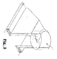
Figure 3 is a perspective view of a damper with two controllable damper elements provided in the flue duct of the see-through stove. - This invention relates to a stove (1), in particular a coal-fired or wood-burning stove, comprising a combustion chamber with at least two closable openings and a flue duct (2), a controllable damper (3) being provided between the combustion chamber and the flue duct (2) in order to close off the abovementioned duct (2). The stove according to this invention is characterized in that the abovementioned damper (3) comprises at least two individually controllable damper elements (4, 5).
- The stove (1) shown in
Figure 1 is a see-through stove with two closable openings lying opposite each other. The see-through stove illustrated is provided with two lifting doors (6, 7) for closing off the openings lying opposite each other. - The damper (3) (see
Figures 2 and3 ) comprises two damper elements (4 and 5) which are operated separately by the two lifting doors (6 and 7). In the figures shown the first lifting door (6) will control a first damper element (5), and the second lifting door (7) will control the second damper element (4). The lifting doors are provided with a mechanical transmission (9) for controlling the different damper elements (4, 5). - Since the damper elements (4, 5) are operated individually by two lifting doors (6, 7) functioning independently of each other, when the fire is on with only one lifting door open the flue duct (2) will be only partially closed off by one damper element, with the result that the fire will remain burning more gently.
- When the fire is burning with two lifting doors (6, 7) open, both damper elements (4, 5) will open fully automatically, so that smoke will no longer go into the living room.
- When the fire is burning with two lifting doors (6, 7) closed, both damper elements (4, 5) will also close, thereby closing off the flue duct (2). This will produce a higher temperature in the stove, resulting in better combustion, considerably greater efficiency and much less pollution of the environment, and much less wood or fuel consumption, and the glass lifting doors which make the see-through stove so interesting remain cleaner for much longer.
- The stove according to this invention is furthermore provided with setting means (8) for adjusting the angle of the two damper elements (4, 5) and thereby adjusting the chimney draught depending on the circumstances. The setting means preferably comprise a threaded rod (8) that can be screwed in and out, being pressed down by a small lip of the door when the door closes, thereby making the damper element close at a particular angle depending on the length of the threaded rod (8).
Claims (8)
- Stove (1) comprising a combustion chamber with at least two closable openings and a flue duct (2), a controllable damper (3) being provided between the combustion chamber and the flue duct (2) in order to close off the abovementioned duct (2), characterized in that the abovementioned damper (3) comprises at least two individually controllable damper elements (4, 5).
- Stove (1) according to claim 1, characterized in that the abovementioned stove comprises a closing means (6, 7) for each opening, each closing means (6, 7) being provided for controlling at least one damper element (4, 5).
- Stove (1) according to claim 2, characterized in that each closing means (6, 7) is movable between an open and a closed position, in a closed position of a closing means (6, 7) the respective damper element (4, 5) being provided so that it partially closes off the flue duct (2).
- Stove (1) according to claim 3, characterized in that when each closing means (6, 7) is in its closed position, the damper elements (4, 5) are provided so that together they close off the abovementioned duct (2).
- Stove (1) according to one of claims 2 to 4, characterized in that the abovementioned closing means (6, 7) is a lifting door, tilting door or revolving door.
- Stove (1) according to one of the preceding claims, characterized in that the abovementioned stove comprises setting means (8) for setting the angle of the two damper elements (4, 5) depending on the chimney draught.
- Stove (1) according to one of the preceding claims, characterized in that the damper (3) comprises two individually controllable damper elements (4, 5).
- Stove (1) according to one of the preceding claims, characterized in that the abovementioned stove is a see-through stove.
Applications Claiming Priority (1)
| Application Number | Priority Date | Filing Date | Title |
|---|---|---|---|
| BE2006/0613A BE1017395A3 (en) | 2006-12-13 | 2006-12-13 | FIREPLACE EQUIPPED WITH A SMOKE VALVE. |
Publications (1)
| Publication Number | Publication Date |
|---|---|
| EP1933090A1 true EP1933090A1 (en) | 2008-06-18 |
Family
ID=38236420
Family Applications (1)
| Application Number | Title | Priority Date | Filing Date |
|---|---|---|---|
| EP07122731A Withdrawn EP1933090A1 (en) | 2006-12-13 | 2007-12-10 | See-through stove provided with a damper |
Country Status (2)
| Country | Link |
|---|---|
| EP (1) | EP1933090A1 (en) |
| BE (1) | BE1017395A3 (en) |
Cited By (1)
| Publication number | Priority date | Publication date | Assignee | Title |
|---|---|---|---|---|
| WO2016142495A1 (en) | 2015-03-11 | 2016-09-15 | Stuv S.A. | Fire box with air-compensation device |
Citations (6)
| Publication number | Priority date | Publication date | Assignee | Title |
|---|---|---|---|---|
| EP0084016A1 (en) * | 1982-01-11 | 1983-07-20 | FONDIS, Société Anonyme dite: | Direct removal of flue gases in heating appliances of the closed type |
| FR2644574A1 (en) * | 1989-03-16 | 1990-09-21 | Frei Martin | Chimney |
| FR2711773A1 (en) * | 1993-10-28 | 1995-05-05 | Labattu Michel | Hearth with lateral glazing provided with one or two convex fronts |
| DE19503229A1 (en) * | 1995-02-02 | 1996-08-08 | Stober & Morlock | Chimney stack section reducer |
| DE29816944U1 (en) * | 1998-09-22 | 1999-02-04 | Esg Emissionsmestechnik Und St | Compact design of a measuring nozzle / throttle valve |
| FR2846730A1 (en) * | 2002-11-05 | 2004-05-07 | Ind B V | Damper plate for smoke duct or flue has adjustable stop formed by bolt with two nuts to limit closure |
-
2006
- 2006-12-13 BE BE2006/0613A patent/BE1017395A3/en not_active IP Right Cessation
-
2007
- 2007-12-10 EP EP07122731A patent/EP1933090A1/en not_active Withdrawn
Patent Citations (6)
| Publication number | Priority date | Publication date | Assignee | Title |
|---|---|---|---|---|
| EP0084016A1 (en) * | 1982-01-11 | 1983-07-20 | FONDIS, Société Anonyme dite: | Direct removal of flue gases in heating appliances of the closed type |
| FR2644574A1 (en) * | 1989-03-16 | 1990-09-21 | Frei Martin | Chimney |
| FR2711773A1 (en) * | 1993-10-28 | 1995-05-05 | Labattu Michel | Hearth with lateral glazing provided with one or two convex fronts |
| DE19503229A1 (en) * | 1995-02-02 | 1996-08-08 | Stober & Morlock | Chimney stack section reducer |
| DE29816944U1 (en) * | 1998-09-22 | 1999-02-04 | Esg Emissionsmestechnik Und St | Compact design of a measuring nozzle / throttle valve |
| FR2846730A1 (en) * | 2002-11-05 | 2004-05-07 | Ind B V | Damper plate for smoke duct or flue has adjustable stop formed by bolt with two nuts to limit closure |
Cited By (1)
| Publication number | Priority date | Publication date | Assignee | Title |
|---|---|---|---|---|
| WO2016142495A1 (en) | 2015-03-11 | 2016-09-15 | Stuv S.A. | Fire box with air-compensation device |
Also Published As
| Publication number | Publication date |
|---|---|
| BE1017395A3 (en) | 2008-08-05 |
Similar Documents
| Publication | Publication Date | Title |
|---|---|---|
| US10677495B2 (en) | Stove | |
| US20040255929A1 (en) | Automatic doors for a fireplace | |
| EP2985531A1 (en) | Fireplace apparatus having remote automatic control function | |
| EP1933090A1 (en) | See-through stove provided with a damper | |
| US20070272232A1 (en) | Cartridge fireplace firebox | |
| US7047962B2 (en) | Air control for a clean burning fireplace | |
| CN201935220U (en) | Energy-saving rapid-combustion furnace convenient to adjust firepower | |
| US6378516B1 (en) | Damper-controlled gas supply system | |
| EP3096084B1 (en) | Fireplace boiler | |
| CA2422169A1 (en) | Gas cooking appliance with louvered burner baffle | |
| US7735482B2 (en) | Combustion control system | |
| KR101694694B1 (en) | Fire wood stove taking a long fire | |
| KR20180001236A (en) | Stove | |
| US2735385A (en) | De ascentiis | |
| EP3255343A1 (en) | Module for discharging flue gases | |
| CN205026734U (en) | Energy -conserving sanitary coal -fired furnace | |
| CN211093498U (en) | Gas stove | |
| ES2259386T3 (en) | HEATING INSERTION FOR A FIREPLACE. | |
| KR20180001237A (en) | Hybrid stove | |
| CN208312440U (en) | Multifunctional range | |
| US1000065A (en) | System of heating and ventilating. | |
| US189006A (en) | Improvement in ventilators | |
| US1728241A (en) | Heating stove | |
| US864159A (en) | Heater. | |
| US218118A (en) | Improvement in fire-place blowers |
Legal Events
| Date | Code | Title | Description |
|---|---|---|---|
| PUAI | Public reference made under article 153(3) epc to a published international application that has entered the european phase |
Free format text: ORIGINAL CODE: 0009012 |
|
| AK | Designated contracting states |
Kind code of ref document: A1 Designated state(s): AT BE BG CH CY CZ DE DK EE ES FI FR GB GR HU IE IS IT LI LT LU LV MC MT NL PL PT RO SE SI SK TR |
|
| AX | Request for extension of the european patent |
Extension state: AL BA HR MK RS |
|
| 17P | Request for examination filed |
Effective date: 20080828 |
|
| AKX | Designation fees paid |
Designated state(s): AT BE BG CH CY CZ DE DK EE ES FI FR GB GR HU IE IS IT LI LT LU LV MC MT NL PL PT RO SE SI SK TR |
|
| AXX | Extension fees paid |
Extension state: HR Payment date: 20080828 |
|
| STAA | Information on the status of an ep patent application or granted ep patent |
Free format text: STATUS: THE APPLICATION IS DEEMED TO BE WITHDRAWN |
|
| 18D | Application deemed to be withdrawn |
Effective date: 20120703 |