EP2503190B1 - Hydromechanisches Getriebe - Google Patents
Hydromechanisches Getriebe Download PDFInfo
- Publication number
- EP2503190B1 EP2503190B1 EP11194483.1A EP11194483A EP2503190B1 EP 2503190 B1 EP2503190 B1 EP 2503190B1 EP 11194483 A EP11194483 A EP 11194483A EP 2503190 B1 EP2503190 B1 EP 2503190B1
- Authority
- EP
- European Patent Office
- Prior art keywords
- housing
- transmission
- hydrostatic
- hydrostatic transmission
- hydromechanical
- Prior art date
- Legal status (The legal status is an assumption and is not a legal conclusion. Google has not performed a legal analysis and makes no representation as to the accuracy of the status listed.)
- Active
Links
Images



Classifications
-
- F—MECHANICAL ENGINEERING; LIGHTING; HEATING; WEAPONS; BLASTING
- F16—ENGINEERING ELEMENTS AND UNITS; GENERAL MEASURES FOR PRODUCING AND MAINTAINING EFFECTIVE FUNCTIONING OF MACHINES OR INSTALLATIONS; THERMAL INSULATION IN GENERAL
- F16H—GEARING
- F16H47/00—Combinations of mechanical gearing with fluid clutches or fluid gearing
- F16H47/02—Combinations of mechanical gearing with fluid clutches or fluid gearing the fluid gearing being of the volumetric type
- F16H47/04—Combinations of mechanical gearing with fluid clutches or fluid gearing the fluid gearing being of the volumetric type the mechanical gearing being of the type with members having orbital motion
-
- F—MECHANICAL ENGINEERING; LIGHTING; HEATING; WEAPONS; BLASTING
- F16—ENGINEERING ELEMENTS AND UNITS; GENERAL MEASURES FOR PRODUCING AND MAINTAINING EFFECTIVE FUNCTIONING OF MACHINES OR INSTALLATIONS; THERMAL INSULATION IN GENERAL
- F16H—GEARING
- F16H57/00—General details of gearing
- F16H57/0006—Vibration-damping or noise reducing means specially adapted for gearings
-
- F—MECHANICAL ENGINEERING; LIGHTING; HEATING; WEAPONS; BLASTING
- F16—ENGINEERING ELEMENTS AND UNITS; GENERAL MEASURES FOR PRODUCING AND MAINTAINING EFFECTIVE FUNCTIONING OF MACHINES OR INSTALLATIONS; THERMAL INSULATION IN GENERAL
- F16H—GEARING
- F16H57/00—General details of gearing
- F16H57/02—Gearboxes; Mounting gearing therein
- F16H57/028—Gearboxes; Mounting gearing therein characterised by means for reducing vibration or noise
-
- F—MECHANICAL ENGINEERING; LIGHTING; HEATING; WEAPONS; BLASTING
- F16—ENGINEERING ELEMENTS AND UNITS; GENERAL MEASURES FOR PRODUCING AND MAINTAINING EFFECTIVE FUNCTIONING OF MACHINES OR INSTALLATIONS; THERMAL INSULATION IN GENERAL
- F16H—GEARING
- F16H37/00—Combinations of mechanical gearings, not provided for in groups F16H1/00 - F16H35/00
- F16H37/02—Combinations of mechanical gearings, not provided for in groups F16H1/00 - F16H35/00 comprising essentially only toothed or friction gearings
- F16H37/06—Combinations of mechanical gearings, not provided for in groups F16H1/00 - F16H35/00 comprising essentially only toothed or friction gearings with a plurality of driving or driven shafts; with arrangements for dividing torque between two or more intermediate shafts
- F16H37/08—Combinations of mechanical gearings, not provided for in groups F16H1/00 - F16H35/00 comprising essentially only toothed or friction gearings with a plurality of driving or driven shafts; with arrangements for dividing torque between two or more intermediate shafts with differential gearing
- F16H37/0833—Combinations of mechanical gearings, not provided for in groups F16H1/00 - F16H35/00 comprising essentially only toothed or friction gearings with a plurality of driving or driven shafts; with arrangements for dividing torque between two or more intermediate shafts with differential gearing with arrangements for dividing torque between two or more intermediate shafts, i.e. with two or more internal power paths
- F16H37/084—Combinations of mechanical gearings, not provided for in groups F16H1/00 - F16H35/00 comprising essentially only toothed or friction gearings with a plurality of driving or driven shafts; with arrangements for dividing torque between two or more intermediate shafts with differential gearing with arrangements for dividing torque between two or more intermediate shafts, i.e. with two or more internal power paths at least one power path being a continuously variable transmission, i.e. CVT
- F16H2037/0866—Power-split transmissions with distributing differentials, with the output of the CVT connected or connectable to the output shaft
- F16H2037/0873—Power-split transmissions with distributing differentials, with the output of the CVT connected or connectable to the output shaft with switching means, e.g. to change ranges
Definitions
- the present invention relates to a continuously variable hydromechanical transmission, in particular for use in the drive train of an agricultural vehicle such as a tractor.
- a hydromechanical transmission conventionally comprises a mechanical branching gear such as a planetary gear and a hydrostatic transmission having two hydrostatic units which are interconnected in a fluid circuit and one of which operates as a pump and the other as a motor.
- a mechanical branching gear such as a planetary gear
- a hydrostatic transmission having two hydrostatic units which are interconnected in a fluid circuit and one of which operates as a pump and the other as a motor.
- the hydrostatic units contribute significantly to the operating noise of a hydromechanical transmission at. Since the noise spectrum of a hydrostatic transmission differs significantly from the usual internal combustion engines and transmissions, the driving noise of a vehicle with hydromechanical drive is noticeable even on busy roads and is distracting.
- Stepless power-split transmissions have become known whose hydraulic modules are mounted in the transmission comprising them by means of elastic elements. In this way, a noise significantly reducing vibration damping is achieved.
- the valve block associated with the hydraulic module is mounted in a vibration-damped manner in the region of the fluid guide arranged in its interior. This achieves a further reduction of the noise level.
- the object of the invention is therefore to provide a hydromechanical transmission with reduced operating noise.
- the object is achieved according to the preamble and characterizing features of claim 1.
- the transmission of vibrations from the hydrostatic transmission can be suppressed to the housing, and the housing does not act or at best to a lesser extent as a soundboard, which radiates the vibrations of the hydrostatic transmission in the environment.
- the housing can also attenuate the airborne sound radiated by the hydrostatic transmission itself when surrounding the hydrostatic transmission like a capsule.
- connection between the housing and the hydrostatic transmission must be at least partially elastic and resilient enough to withstand the driving and driving forces acting between the hydrostatic transmission and the environment.
- a Such compound is inventively formed by pins which are surrounded by a damping of the vibrations of the hydrostatic transmission elastic sleeve.
- a bore of the housing, the pin and sleeve receives, be closed to the outside by a screwed lid.
- At least one of the pins is mounted in opposite walls of the housing, and the hydrostatic transmission is fixed between the walls on the pin.
- At least one other of the pins is bolted in a wall of the housing.
- a pin does not necessarily have to be supported on two sides in order to be able to support at least part of the weight of the hydrostatic transmission. Instead, a free end of the pin can engage in a recess of a bearing bridge of the hydrostatic transmission. Because of this Pen does not have to cross the housing, it is more flexible placeable than a continuous pen.
- the elastic sleeve is preferably mounted around the free end in such a bolted pin.
- a pressurized fluid line extending between the hydrostatic transmission and the housing e.g. In order to control the position of the turntable and cylinder block relative to each other, or to compensate for hydraulic fluid losses of the hydrostatic units, according to the invention, in order not to serve as a bridge for the transmission of vibrations, between a solid at the hydrostatic transmission portion and a housing fixed portion at least one telescopic and / or pivotal connection.
- a respective telescopic and / or pivotable connection between an inner pipe section or compensating section and the fixed section on the hydrostatic transmission and between the inner pipe section or compensating section and the fixed portion on the housing is provided.
- Such a connection allows a translational vibration of the hydrostatic transmission relative to the housing in three mutually orthogonal spatial directions.
- the telescopic and / or pivotable connection comprises in each case an outer pipe section, the inner pipe section engaging with radial play in the outer pipe section over a given length and a seal which the radial clearance between the pipe sections fills only a fraction of this length.
- a seal allows both a displacement of the pipe sections relative to one another in the longitudinal direction thereof, as well as a rotation about orthogonal to the longitudinal direction of the pipe sections axes.
- Fig. 1 illustrated in a schematic representation arrangement and interaction of the moving parts of the hydromechanical transmission according to the invention.
- a drive shaft 1 of the hydromechanical transmission is connected to a motor 2 indicated schematically by a piston acting on the drive shaft 1.
- the drive shaft 1 extends longitudinally through the entire transmission up to a motor 2 opposite Zapfwellenanschlüss 3.
- the branching gear comprises in the illustrated embodiment, a two-stage planetary gear 17, of which a sun gear 4 is mounted approximately centrally on the drive shaft 1.
- the sun gear 4 meshes with planet wheels 5, the planet carrier 6 is fixedly connected to an output shaft 7 of the planetary gear 17.
- This output shaft 7 is a coaxial to the drive shaft 1 hollow shaft.
- the planet carrier 6 at the same time carries planet wheels 8 of a second stage of the planetary gear 17.
- Each of the planetary gears 8 is connected to one of the planet gears 5 rotationally fixed.
- the planet gears 8 mesh on the one hand with a second sun gear 9, which rotatably together with a gear 10 on a second rotatable about the drive shaft 1 hollow shaft 11, and on the other hand with a ring gear 13, which surrounds a hollow shaft 11 further hollow shaft 12 with a gear 14 is connected.
- the planet carrier 6 surrounds bowl-shaped planetary gears 5, 8 and sun gears 4, 9 and the ring gear 13 and is provided at its outer periphery, approximately in a same plane with the ring gear 13, with a ring gear 20.
- a first countershaft 15 is surrounded by two hollow shafts, each with a gear 21, 22 and has a coupling 19 for selectively coupling one of the gears 21, 22 to the countershaft 15.
- a curved tooth coupling 16 connects the first countershaft 15 with a shaft 18 of a first hydrostatic unit 23.
- the curved tooth coupling 16 comprises in a conventional manner, such as in DE-AS 1 208 565 .
- DE-OS 2 355 433 and DE-OS 38 11 790 as well as the GB-A 2 040 397 shown, a bushing with internal curved toothing and a pinion, which engages angularly and radially displaceable in the bushing.
- the curved tooth coupling 16 connects the shafts 15, 18 torque-locking and thereby allows a limited displacement of the shafts 15, 18 to each other in the axial direction and pivotal movements of the shafts 15, 18 relative to each other about an axis perpendicular to the longitudinal direction of the countershaft 15 axis.
- the gear 22 meshes with the gear 14 coupled to the ring gear 13.
- the gear 21 is coupled via a reversing gear 23 to a gear 24 on the drive shaft 1.
- a second countershaft 25 also has a coupling 29 for selectively coupling the countershaft 25 to gear wheels 30 and 31 coaxial therewith, and a curved gear coupling 26 connects the second countershaft 25 to a shaft section 28 of a second hydrostatic unit 33.
- the hydrostatic units 23, 33 are per se known axial piston units with a non-rotatably connected to the respective shaft 18, 28 turntable 32, engage the piston of a cylinder block 34 each via ball joints.
- the rotation of the rotary disk 32 drives an oscillating movement of the pistons, the amplitude of which increases with the pivoting angle of the cylinder block 34 relative to the shaft 18 or 28 and determines the return volume of the respective unit 23 or 33.
- Fig. 1 shows the unit 23 at a minimum tilt angle of 0 ° and the unit 33 at a maximum tilt angle of 45 °.
- the units 23, 33 are interconnected by an in Fig. 1 not shown fluid line connected in a circle, so that one of the units 23, 33 pumped hydraulic fluid drives the other unit.
- Each of the two units 23, 33 can operate both as a pump and as a motor, whereby the ratio of the hydrostatic transmission 23, 33 formed by the two units 23, 33 is infinitely variable by varying the pivoting angle of the hydrostatic units 23, 33.
- the translation of the entire hydro-mechanical transmission depends on the pivoting angles of the hydrostatic units and on the positions of the clutches 19, 29.
- the position of the clutch 19 determines the sign of the translation, ie the direction of rotation of the output shaft 7.
- the clutch 29 allows switching between fast and slow driving at the same direction.
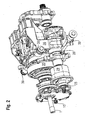
- Fig. 2 shows a perspective view of the with reference to Fig. 1 described transmission.
- the right part of the representation of the Fig. 2 takes the branching gear with the countershafts 15, 25 and the planetary gear 17 a.
- the planetary gear 17 and the meshing with the ring gear 20 gear 31 of the countershaft 25 are bent in a housing 35.
- a bearing bridge 36 (not visible in the figure) bearings are housed, the waves 18, 28 of the hydrostatic units 23, 33 hold.
- two housings 37 are pivoted about vertically through the rotors 32 extending axes, each receiving the cylinder block 34 of one of the two hydrostatic units 23, 33.
- Fig. 2 only the housing 37 of the unit 33 is visible.
- the pressurized fluid line connecting the hydrostatic units 23, 33 to each other passes through bores within the bearing bridge 36.
- the bearing bridge 36 is in an in Fig. 2 Not shown, sound-insulating outer housing attached.
- the bearing bridge 36 in the outer housing are horizontally, transversely to the shafts 1, 15, 25 oriented and engaging respectively in bores of the bearing bridge 36 and the outer housing pins 38, 39th
- Fig. 3 shows in a perspective view of the bearing bridge 36 and a surrounding outer housing 40, which is provided so as not to a shown, surrounding the branching outer housing to be joined together to a soundproofing capsule enclosing the entire hydromechanical transmission.
- the bearing bridge 36 has here substantially the shape of a round arch, the ends of which are extended downwards by two stubby columns which receive the bearings of the shaft sections 18 and 28 respectively.
- the waves 18, 28 are hidden inside the pillars; two externally toothed stub shafts 41 visible at the front of the pillars of the bearing bridge 36 each form the pinions of the above-mentioned gear couplings 16 and 26, respectively.
- the toothed couplings 16, 26 completing bushings with recesses complementary to the stubs 41 are located at the ends of FIGS Fig. 3 not shown countershafts 15, 25.
- the lower of the pins, 39 extends transversely through the housing 40 and is anchored in bores from opposite side walls of the housing 40.
- the bearing bridge 36 is fixed to the pin 39 by means of two forming the lower ends of the columns, the pin 39 clamping clamps 42, one of which, below the hydrostatic unit 23, hidden by the housing 40.
- the pins 38 each extend only through a side wall of the housing 40 and are received in a bore 43 of the bearing bridge 36.
- a window is recessed.
- a bushing frame 61 is mounted, its function later in conjunction with Fig. 6 is explained.
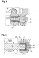
- Fig. 4 shows a section through one of each extending only through a side wall of the housing 40 pins 38.
- the pin 38 includes from outside to inside a ffersechskant 44, provided with a sealing ring, applied to the housing 40 flange 45, a threaded portion 46, the Pin 38 fixed in the wall of the housing 40, a portion with a shaft fit, which allows accurate positioning of the pin 38 in the housing 40, and engaging in the bore 43 of the bearing bracket 36, surrounded by an elastomer sleeve 47 end portion 48. While the pin 38 is rigidly connected to the housing 40, the elastomeric sleeve 47 allows movements of the bearing bridge 36 relative to the pin 38 and consequently also relative to the housing 40th
- Fig. 5 shows a section through the lower, extending through both side walls of the housing 40 pin 39.
- the clamps 42 attack without an intermediate elastomer layer on the lower pin 39 at. Instead, in each case a so-called ultra-sleeve 49 is pushed onto the slightly tapered ends of the pin 39, each having an elastomer layer 50 between rigid outer and inner sleeves 51, 52 in a conventional manner.
- the ultra-bushing 49 is fixed to the pin 39 by clamping its inner sleeve 52 between a shoulder 53 of the pin 39 and a plate 54 bolted to the end of the pin.
- the pin 39 is fixed in the housing 40 in the axial direction by two covers 55, which are screwed from the outside into the bores of the housing 40, in which the pin 39 engages from the inside. Between each end of the pin and the lid opposite it, in each case an elastomeric disk 56 is clamped.
- the elastomeric disk 56 is slightly compressible in the axial direction of the pin 39 and, together with the ultra-sleeve 49, allows damped oscillatory movements of the pin 39 relative to the housing 40 in three spatial directions.
- Fig. 6 illustrates the oil supply of the hydrostatic transmission.
- Supply lines for hydraulic oil are led out of the bearing bridge 36 through the housing 40, on the one hand, in order to continuously compensate oil losses of the hydrostatic units 23, 33, on the other hand, to adjust the pivoting angle of the cylinder blocks of the two units 23, 33 via hydraulic actuators.
- Fig. 6 shows in a perspective view of two of these actuators 57, which are mounted above the controlled by them housing 37 of the hydrostatic unit 23 to the bearing bridge 36.
- the housing 40 is in Fig. 6 omitted, only the already shown in Fig. 3 shown bushing frame 61, which fills the window of the housing 40 tightly.
- the supply lines must be reasonably rigid walls to withstand high internal pressures, but the more rigid they are, the more efficiently they transmit vibrations of the hydrostatic units 23, 33 to the housing 40.
- In order to avoid vibration transmission via the supply lines is between one the bearing bridge fixed line section 58th and a fixed to the lead-through frame 61 line section 59 a connection from in Fig. 7 provided in the longitudinal section type shown.
- the sections 58, 59 are here widened at their ends in each case to a sleeve 62, in which a rigid-walled pipe section 60 engages with play in the axial and radial directions.
- the pipe section 60 is provided over its entire length with an elastomer coating 63, which is thickened at the ends in each case to a bead 64 tightly adjacent to the inner surface of the sleeve 62.
- the axial extent of the region in which the bead 64 contacts the sleeve 62 is significantly smaller than the diameter of the sleeve 62, so that the tube piece 60 not only move longitudinally against the sleeves 62, but also in both sleeves. 62 can swing around small angles.
- the sleeves 62 and engaging ends of the tube 60 thus each form a telescopic and pivotal connection.
- the line sections 58, 59 are consequently also movable relative to one another in three spatial directions and do not transmit any vibrations of the hydrostatic units 23, 33 to the housing 40.
Landscapes
- Engineering & Computer Science (AREA)
- General Engineering & Computer Science (AREA)
- Mechanical Engineering (AREA)
- General Details Of Gearings (AREA)
- Motor Power Transmission Devices (AREA)
Description
- Die vorliegende Erfindung betrifft ein stufenloses hydromechanisches Getriebe, insbesondere zur Verwendung im Antriebsstrang eines landwirtschaftlichen Fahrzeugs wie etwa eines Traktors.
- Ein hydromechanisches Getriebe umfasst herkömmlicherweise ein mechanisches Verzweigungsgetriebe wie etwa ein Planetengetriebe und ein hydrostatisches Getriebe mit zwei hydrostatischen Einheiten, die in einem Fluidkreislauf miteinander verbunden sind und von denen jeweils eine als Pumpe und die andere als Motor arbeitet. Indem z.B. durch Schwenken eines Zylinderblocks einer Einheit gegen eine Drehscheibe, an der die Kolben des Zylinderblocks angreifen, das Schluckvolumen wenigstens einer dieser beiden hydrostatischen Einheiten variiert wird, ist eine stufenlose Verstellung der Übersetzung des hydrostatischen Getriebes realisierbar, und indem das hydrostatische Getriebe mit einem Ausgleichsanschluss des Verzweigungsgetriebes drehverbunden ist, beeinflusst es die Drehzahl einer Ausgangswelle des Verzweigungsgetriebes proportional zu seinem eigenen Übersetzungsverhältnis.
- Die hydrostatischen Einheiten tragen erheblich zum Betriebsgeräusch eines hydromechanischen Getriebes bei. Da sich das Geräuschspektrum eines hydrostatischen Getriebes erheblich von dem üblicher Verbrennungsmotoren und Getrieben unterscheidet, ist das Fahrgeräusch eines Fahrzeugs mit hydromechanischem Antrieb selbst auf stark befahrenen Straßen auffällig und wird als störend empfunden.
- Aus der
DE 43 00 456 A1 sowie derDE 199 33 822 A1 sind stufenlose leistungsverzweigte Getriebe bekannt geworden, deren Hydraulikmodule in dem sie umfassenden Getriebe mittels elastischer Elemente gelagert sind. Auf diese Weise wird eine die Geräusche erheblich reduzierende Schwingungsdämpfung erzielt. Aus der gattungsgemäßenEP 0 902213 A1 ist auch der dem Hydromodul zugeordnete Ventilblock im Bereich der in seinem Inneren angeordneten Fluidführung schwingungsgedämpft gelagert. Damit wird eine weitere Reduzierung des Geräuschpegels erreicht. - Aufgabe der Erfindung ist daher, ein hydromechanisches Getriebe mit reduziertem Betriebsgeräusch zu schaffen.
- Die Aufgabe wird gemäß den oberbegrifflichen und kennzeichnenden Merkmalen des Anspruches 1 gelöst. So kann die Übertragung von Schwingungen vom hydrostatischen Getriebe auf das Gehäuse unterdrückt werden, und das Gehäuse wirkt nicht oder allenfalls in geringem Umfang als Resonanzboden, der die Schwingungen des hydrostatischen Getriebes in die Umgebung abstrahlt.
- Das Gehäuse kann auch vom hydrostatischen Getriebe selber abgestrahlten Luftschall dämpfen, wenn es das hydrostatische Getriebe kapselartig umgibt.
- Die Verbindung zwischen Gehäuse und dem hydrostatischen Getriebe muss wenigstens teilweise elastisch und belastbar genug sein, um den zwischen dem hydrostatischen Getriebe und der Umgebung wirkenden An- und Abtriebskräften standhalten zu können. Eine solche Verbindung wird erfindungsgemäß durch Stifte gebildet, die mit einer die Schwingungen des hydrostatischen Getriebes dämpfenden elastischen Hülse umgeben sind.
- Für die Dämpfung der Schwingungen ist nicht ausschlaggebend, ob die elastische Hülse jeweils zwischen einem Stift und dem hydrostatischen Getriebe oder zwischen dem Stift und dem Gehäuse angeordnet ist. Für den Fall, das ein Austausch der Hülse erforderlich werden sollte, ist allerdings eine zwischen Stift und Gehäuse angeordnete Hülse im Allgemeinen besser zugänglich.
- Zum Schutz der Hülse oder auch, um den Stift in axialer Richtung zu sichern, kann eine Bohrung des Gehäuses, die Stift und Hülse aufnimmt, nach außen durch einen eingeschraubten Deckel verschlossen sein.
- Um eine hohe Belastbarkeit zu gewährleisten, ist erfindungsgemäß wenigstens einer der Stifte in sich gegenüberliegenden Wänden des Gehäuses gelagert, und das hydrostatische Getriebe ist zwischen den Wänden an dem Stift befestigt.
- Vorzugsweise ist wenigstens ein anderer der Stifte in einer Wand des Gehäuses verschraubt. Ein solcher Stift muss nicht unbedingt zweiseitig gelagert zu sein, um wenigstens einen Teil des Gewichts des hydrostatischen Getriebes tragen zu können. Stattdessen kann ein freies Ende des Stifts in eine Aussparung einer Lagerbrücke des hydrostatischen Getriebes eingreifen. Da dieser Stift das Gehäuse nicht kreuzen muss, ist er flexibler platzierbar als ein durchgehender Stift.
- Die elastische Hülse ist bei einem solchen verschraubten Stift vorzugsweise um das freie Ende herum angebracht.
- Eine Druckfluidleitung, die sich zwischen dem hydrostatischen Getriebe und dem Gehäuse erstreckt, z.B. um die Stellung von Drehscheibe und Zylinderblock relativ zueinander zu steuern, oder um Hydraulikfluidverluste der hydrostatischen Einheiten auszugleichen, weist erfindungsgemäß, um nicht als Brücke für die Übertragung von Schwingungen zu dienen, zwischen einem am hydrostatischen Getriebe festen Abschnitt und einem am Gehäuse festen Abschnitt wenigstens eine teleskopische und/oder schwenkbare Verbindung auf.
- Vorzugsweise ist je eine teleskopische und/oder schwenkbare Verbindung zwischen einem inneren Rohrabschnitt bzw. Ausgleichsabschnitt und dem am hydrostatischen Getriebe festen Abschnitt sowie zwischen dem inneren Rohrabschnitt bzw. Ausgleichsabschnitt und dem am Gehäuse festen Abschnitt vorgesehen. Eine solche Verbindung erlaubt eine Translationsschwingung des hydrostatischen Getriebes relativ zum Gehäuse in drei zueinander orthogonalen Raumrichtungen.
- Die teleskopische und/oder schwenkbare Verbindung umfasst erfindungsgemäß jeweils einen äußeren Rohrabschnitt, den mit radialem Spiel in den äußeren Rohrabschnitt auf einer gegebenen Länge eingreifenden inneren Rohrabschnitt und eine Dichtung, die das radiale Spiel zwischen den Rohrabschnitten nur auf einem Bruchteil dieser Länge ausfüllt. Eine solche Dichtung erlaubt sowohl eine Verschiebung der Rohrabschnitte relativ zueinander in deren Längsrichtung, als auch eine Drehung um zur Längsrichtung der Rohrabschnitte orthogonale Achsen.
- Um eine Schwingungsübertragung zwischen dem hydrostatischen Getriebe und dem Ausgleichsgetriebe zu vermeiden, ist erfindungsgemäß wenigstens eine Anschlusswelle des hydrostatischen Getriebes mit dem Verzweigungsgetriebe über eine Bogenzahnkupplung, insbesondere drehmomentschlüssig, aber dennoch in Maßen axial beweglich und schwenkbar, verbunden.
- Weitere Merkmale und Vorteile der Erfindung ergeben sich aus der nachfolgenden Beschreibung von Ausführungsbeispielen unter Bezugnahme auf die beigefügten Figuren. Es zeigen:
- Fig. 1
- eine schematische Darstellung eines hydromechanischen Getriebes, an dem die vorliegende Erfindung anwendbar ist;
- Fig. 2
- eine perspektivische Ansicht des hydromechanischen Getriebes;
- Fig. 3
- eine perspektivische Ansicht des hydrostatischen Getriebes und eines es umgebenden Gehäuses;
- Fig. 4
- einen schematischen Schnitt durch eine erste elastische Verbindung zwischen dem hydromechanischen Getriebe und dem Gehäuse;
- Fig. 5
- einen zu
Fig. 4 analogen Schnitt durch eine zweite Verbindung des hydromechanischen Getriebes mit dem Gehäuse; - Fig. 6
- eine Durchführung für Hydraulikfluid durch die Wand des Gehäuses; und
- Fig. 7
- einen schematischen Längsschnitt durch eine Leitung der Durchführung.
-
Fig. 1 veranschaulicht in einer schematischen Darstellung Anordnung und Zusammenwirken der beweglichen Teile des erfindungsgemäßen hydromechanischen Getriebes. Eine Antriebswelle 1 des hydromechanischen Getriebes ist mit einem schematisch durch einen an der Antriebswelle 1 angreifenden Kolben angedeuteten Motor 2 verbunden. Die Antriebswelle 1 erstreckt sich längs durch das gesamte Getriebe bis zu einem dem Motor 2 gegenüberliegendem Zapfwellenanschlüss 3. Das Verzweigungsgetriebe umfasst im dargestellten Ausführungsbeispiel ein zweistufiges Planetengetriebe 17, von dem ein Sonnenrad 4 in etwa mittig auf der Antriebswelle 1 befestigt ist. Das Sonnenrad 4 kämmt mit Planetenrädern 5, deren Planetenträger 6 fest mit einer Ausgangswelle 7 des Planetengetriebes 17 verbunden ist. Diese Ausgangswelle 7 ist eine zur Antriebswelle 1 koaxiale Hohlwelle. Der Planetenträger 6 trägt gleichzeitig Planetenräder 8 einer zweiten Stufe des Planetengetriebes 17. Jedes der Planetenräder 8 ist mit einem der Planetenräder 5 drehfest verbünden. Die Planetenräder 8 kämmen einerseits mit einem zweiten Sonnenrad 9, das zusammen mit einem Zahnrad 10 drehfest auf einer zweiten um die Antriebswelle 1 drehbaren Hohlwelle 11 sitzt, und andererseits mit einem Hohlrad 13, das über eine die Hohlwelle 11 umgebende weitere Hohlwelle 12 mit einem Zahnrad 14 verbunden ist. - Der Planetenträger 6 umgibt schüsselförmig die Planetenräder 5, 8 und Sonnenräder 4, 9 und das Hohlrad 13 und ist an seinem Außenumfang, in etwa in einer gleichen Ebene mit dem Hohlrad 13, mit einem Zahnkranz 20 versehen.
- Eine erste Vorgelegewelle 15 ist von zwei Hohlwellen mit jeweils einem Zahnrad 21, 22 umgeben und weist eine Kupplung 19 zum wahlweise Ankuppeln eines der Zahnräder 21, 22 an die Vorgelegewelle 15 auf. Eine Bogenzahnkupplung 16 verbindet die erste Vorgelegewelle 15 mit einer Welle 18 einer ersten hydrostatischen Einheit 23. Die Bogenzahnkupplung 16 umfasst in an sich bekannter Weise, wie z.B. in
DE-AS 1 208 565 DE-OS 2 355 433 DE-OS 38 11 790 GB-A 2 040 397 - Das Zahnrad 22 kämmt mit dem an das Hohlrad 13 gekoppelten Zahnrad 14. Das Zahnrad 21 ist über ein Umkehrrad 23 an ein Zahnrad 24 auf der Antriebswelle 1 gekoppelt.
- Analog zur ersten Vorgelegewelle 15 weist auch eine zweite Vorgelegewelle 25 eine Kupplung 29 zum wahlweisen Ankoppeln der Vorgelegewelle 25 an zu ihr koaxiale Zahnräder 30 bzw. 31 auf, und eine Bogenzahnkupplung 26 verbindet die zweite Vorgelegewelle 25 mit einem Wellenabschnitt 28 einer zweiten hydrostatischen Einheit 33.
- Die hydrostatischen Einheiten 23, 33 sind an sich bekannte Axialkolbeneinheiten mit einer drehfest mit der jeweiligen Welle 18, 28 verbundenen Drehscheibe 32, an der Kolben eines Zylinderblocks 34 jeweils über Kugelgelenke angreifen. Die Drehung der Drehscheibe 32 treibt eine oszillierende Bewegung der Kolben an, deren Amplitude mit dem Schwenkwinkel des Zylinderblocks 34 relativ zur Welle 18 bzw. 28 zunimmt und das Schl-uckvolumen der betreffenden Einheit 23 bzw. 33 bestimmt.
Fig. 1 zeigt die Einheit 23 bei einem minimalen Schwenkwinkel von 0° und die Einheit 33 bei einem maximalen Schwenkwinkel von 45°. - Die Einheiten 23, 33 sind untereinander durch eine in
Fig. 1 nicht dargestellte Fluidleitung im Kreis verbunden, so dass von einer der Einheiten 23, 33 gepumptes Hydraulikfluid die jeweils andere Einheit antreibt. Jede der beiden Einheiten 23, 33 kann sowohl als Pumpe als auch als Motor arbeiten, wobei durch Variieren der Schwenkwinkel der hydrostatischen Einheiten 23, 33 die Übersetzung des von den zwei Einheiten 23, 33 gebildeten hydrostatischen Getriebes stufenlos veränderbar ist. Die Übersetzung des gesamten hydromechanischen Getriebes hängt von den Schwenkwinkeln der hydrostatischen Einheiten und von den Stellungen der Kupplungen 19, 29 ab. Die Stellung der Kupplung 19 bestimmt das Vorzeichen der Übersetzung, d.h. die Drehrichtung der Ausgangswelle 7. Die Kupplung 29 ermöglicht das Umschalten zwischen schneller und langsamer Fahrt bei gleichbleibender Richtung. -
Fig. 2 zeigt eine perspektivische Ansicht des mit Bezug aufFig. 1 beschriebenen Getriebes. Den rechten Teil der Darstellung derFig. 2 nimmt das Verzweigungsgetriebe mit den Vorgelegewellen 15, 25 und dem Planetengetriebe 17 ein. Das Planetengetriebe 17 sowie das mit dem Zahnkranz 20 kämmende Zahnrad 31 der Vorgelegewelle 25 sind in einem Gehäuse 35 verbogen. - In einer Lagerbrücke 36 sind (in der Fig. nicht sichtbar) Lager untergebracht, die, die Wellen 18, 28 der hydrostatischen Einheiten 23, 33 halten. An der vom Verzweigungsgetriebe abgewandten Seite der Lagerbrücke 36 sind zwei Gehäuse 37 um vertikal durch die Drehscheiben 32 verlaufende Achsen schwenkbar angelenkt, die jeweils den Zylinderblock 34 einer der beiden hydrostatischen Einheiten 23, 33 aufnehmen. In
Fig. 2 ist nur das Gehäuse 37 der Einheit 33 sichtbar. Die Druckfluidleitung, die die hydrostatischen Einheiten 23, 33 miteinander verbindet, verläuft durch Bohrungen innerhalb der Lagerbrücke 36. - Die Lagerbrücke 36 ist in einem in
Fig. 2 nicht gezeigten schallisolierenden äußeren Gehäuse befestigt. Zur Befestigung der Lagerbrücke 36 im äußeren Gehäuse dienen horizontal, quer zu den Wellen 1, 15, 25 orientierte und jeweils in Bohrungen der Lagerbrücke 36 bzw. des äußeren Gehäuses eingreifende Stifte 38, 39. -
Fig. 3 zeigt in einer perspektivischen Ansicht die Lagerbrücke 36 und ein sie umgebendes äußeres Gehäuse 40, das vorgesehen ist, um mit einem nicht gezeigten, das Verzweigungsgetriebe umgebenden äußeren Gehäuse zu einer das gesamte hydromechanische Getriebe umschließenden schallisolierenden Kapsel zusammengefügt zu werden. Die Lagerbrücke 36 hat hier im Wesentlichen die Gestalt eines Rundbogens, dessen Enden nach unten durch zwei gedrungene Säulen verlängert sind, welche die Lager der Wellenabschnitte 18 bzw. 28 aufnehmen. Die Wellen 18, 28 sind im Innern der Säulen verborgen; zwei an der Vorderseite der Säulen der Lagerbrücke 36 sichtbare außen verzahnte Wellenstümpfe 41 bilden jeweils dieRitzel der oben erwähnten Bogenzahnkupplungen 16 bzw. 26. Die Bogenzahnkupplungen 16, 26 vervollständigende Buchsen mit zu den Wellenstümpfen 41 komplementären Aussparungen befinden sich an den Enden der inFig. 3 nicht gezeigten Vorgelegewellen 15, 25. - Der untere der Stifte, 39, erstreckt sich quer durch das Gehäuse 40 und ist in Bohrungen von einander gegenüberliegenden Seitenwänden des Gehäuses 40 verankert. Die Lagerbrücke 36 ist an dem Stift 39 mittels zweier die unteren Enden der Säulen bildender, den Stift 39 klemmender Schellen 42 fixiert, von denen eine, unterhalb der hydrostatischen Einheit 23, durch das Gehäuse 40 verborgen ist. Die Stifte 38 erstrecken sich jeweils nur durch eine Seitenwand des Gehäuses 40 und sind in einer Bohrung 43 der Lagerbrücke 36 aufgenommen.
- An einer vom Betrachter abgewandten Seitenwand des Gehäuses 40 ist ein Fenster ausgespart. In dem Fenster ist ein Durchführungsrahmen 61 montiert, dessen Funktion später in Verbindung mit
Fig. 6 erläutert wird. -
Fig. 4 zeigt einen Schnitt durch einen der sich jeweils nur durch eine Seitenwand des Gehäuses 40 erstreckenden Stifte 38. Der Stift 38 umfasst von außen nach innen einen Schraubsechskant 44, einen mit einem Dichtring versehenen, an Gehäuse 40 anliegenden Flansch 45, einen Gewindeabschnitt 46, der den Stift 38 in der Wand des Gehäuses 40 fixiert, einen Abschnitt mit Wellenpassung, der eine genaue Positionierung des Stiftes 38 im Gehäuse 40 erlaubt, sowie einen in die Bohrung 43 der Lagerbrücke 36 eingreifenden, von einer Elastomerhülse 47 umgebenen Endabschnitt 48. Während der Stift 38 starr mit dem Gehäuse 40 verbunden ist, erlaubt die Elastomerhülse 47 Bewegungen der Lagerbrücke 36 relativ zum Stift 38 und folglich auch relativ zum Gehäuse 40. -
Fig. 5 zeigt einen Schnitt durch den unteren, sich durch beide Seitenwände des Gehäuses 40 erstreckenden Stift 39. Die Schellen 42 greifen ohne eine dazwischen liegende Elastomerschicht an dem unteren Stift 39 an. Stattdessen ist auf die geringfügig verjüngten Enden des Stifts 39 jeweils eine sogenannte Ultrabuchse 49 aufgeschoben, die in an sich bekannter Weise jeweils eine Elastomerschicht 50 zwischen starren äußeren und inneren Hülsen 51, 52 aufweist. Die Ultrabuchse 49 ist am Stift 39 fixiert durch Klemmung ihrer inneren Hülse 52 zwischen einer Schulter 53 des Stifts 39 und einer am Ende des Stifts angeschraubten Platte 54. Der Stift 39 ist in dem Gehäuse 40 in axialer Richtung fixiert durch zwei Deckel 55, die von außen in die Bohrungen des Gehäuses 40 eingeschraubt sind, in die der Stift 39 von innen eingreift. Zwischen jedem Ende des Stifts und dem ihm gegenüberliegenden Deckel ist jeweils eine Elastomerscheibe 56 eingeklemmt. Die Elastomerscheibe 56 ist in axialer Richtung des Stifts 39 geringfügig stauchbar und erlaubt zusammen mit der Ultrabuchse 49 gedämpfte Schwingbewegungen des Stifts 39 relativ zum Gehäuse 40 in drei Raumrichtungen. -
Fig. 6 veranschaulicht die Ölversorgung des hydrostatischen Getriebes. Versorgungsleitungen für Hydrauliköl sind von der Lagerbrücke 36 durch das Gehäuse 40 herausgeführt, einerseits, um Ölverluste der hydrostatischen Einheiten 23, 33 kontinuierlich ausgleichen zu können, andererseits, um über hydraulische Stellglieder die Schwenkwinkel der Zylinderblöcke der beiden Einheiten 23, 33 einstellen zu können.Fig. 6 zeigt in einer perspektivischen Ansicht zwei dieser Stellglieder 57, die oberhalb des von ihnen gesteuerten Gehäuses 37 der hydrostatischen Einheit 23 an der Lagerbrücke 36 montiert sind. Das Gehäuse 40 ist inFig. 6 weggelassen, gezeigt ist lediglich der bereits inFig. 3 gezeigte Durchführungsrahmen 61, der das Fenster des Gehäuses 40 dicht ausfüllt. Die Versorgungsleitungen müssen einigermaßen starrwandig sein, um hohe Innendrücke auszuhalten, doch je starrer sie sind, um so effizienter übertragen auch sie Schwingungen der hydrostatischen Einheiten 23, 33 auf das Gehäuse 40. Um eine Schwingungsübertragung auch über die Versorgungsleitungen zu vermeiden, ist zwischen einem an der Lagerbrücke festen Leitungsabschnitt 58 und einem am Durchführungsrahmen 61 festen Leitungsabschnitt 59 eine Verbindung vom inFig. 7 im Längsschnitt gezeigten Typ vorgesehen. Die Abschnitte 58, 59 sind hier an ihren Enden jeweils zu einer Muffe 62 aufgeweitet, in die ein starrwandiges Rohrstück 60 mit Spiel in axialer und radialer Richtung eingreift. Das Rohrstück 60 ist auf seiner ganzen Länge mit einem Elastomerüberzug 63 versehen, der an den Enden jeweils zu einem an der Innenfläche der Muffe 62 dicht anliegenden Wulst 64 verdickt ist. Die axiale Ausdehnung des Bereichs, in dem der Wulst 64 die Muffe 62 berührt, ist erheblich kleiner als der Durchmesser der Muffe 62, so dass das Rohrstück 60 sich nicht nur in Längsrichtung gegen die Muffen 62 bewegen, sondern auch in beiden Muffen. 62 um kleine Winkel schwenken kann. Die Muffen 62 und darin eingreifenden Enden des Rohrstücks 60 bilden so jeweils eine teleskopische und schwenkbare Verbindung. Auch die Leitungsabschnitte 58, 59 sind folglich gegeneinander in drei Raumrichtungen beweglich und übertragen keine Schwingungen der hydrostatischen Einheiten 23, 33 auf das Gehäuse 40. -
- 1
- Antriebswelle
- 2
- Motor
- 3
- Zapfwellenanschluss
- 4
- Sonnenrad
- 5
- Planetenrad
- 6
- Planetenträger
- 7
- Ausgangswelle
- 8
- Planetenrad
- 9
- Sonnenrad
- 10
- Zahnrad
- 11
- Hohlwelle
- 12
- Hohlwelle
- 13
- Hohlrad
- 14
- Zahnrad
- 15
- Vorgelegewelle
- 16
- Bogenzahnkupplung
- 17
- Planetengetriebe
- 18
- Wellenabschnitt
- 19
- Kupplung
- 20
- Zahnkranz
- 21
- Zahnrad
- 22
- Zahnrad
- 23
- hydrostatische Einheit
- 24
- Zahnrad
- 25
- Vorgelegewelle
- 26
- Bogenzahnkupplung
- 27 28
- Wellenabschnitt
- 29
- Kupplung
- 30
- Zahnrad
- 31
- Zahnrad
- 32
- Drehscheibe
- 33
- hydrostatische Einheit
- 34
- Zylinderblock
- 35
- Gehäuse
- 36
- Lagerbrücke
- 37
- Gehäuse
- 38
- Stift
- 39
- Stift
- 40
- äußeres Gehäuse
- 41
- Wellenstumpf
- 42
- Schelle
- 43
- Bohrung
- 44
- Schraubsechskant
- 45
- Flansch
- 46
- Gewindeabschnitt
- 47
- Elastomerhülse
- 48
- Endabschnitt
- 49
- Ultrabuchse
- 50
- Elastomerschicht
- 51
- äußere Hülse
- 52
- innere Hülse
- 53
- Schulter
- 54
- Platte
- 55
- Deckel
- 56
- Elastomerscheibe
- 57
- Stellglied
- 58
- Leitungsabschnitt
- 59
- Leitungsabschnitt
- 60
- Rohrstück
- 61
- Durchführungsrahmen
- 62
- Muffe
- 63
- Elastomerüberzug
- 64
- Wulst
Claims (7)
- Hydromechanisches Getriebe mit einem in einem Gehäuse (40) aufgenommenen mechanischen Verzweigungsgetriebe (4-31) und einem mit dem Verzweigungsgetriebe (4-31) zusammenwirkenden stufenlos verstellbaren hydrostatischen Getriebe (23, 33), wobei das hydrostatische Getriebe (23, 33) zumindest mit dem Gehäuse (40) über Dämpfungselemente (47; 50; 64) nachgiebig verbunden ist, wobei eine Druckfluidleitung (58, 59, 60) vorgesehen ist, die zwischen einem am hydrostatischen Getriebe (23,33) festen Abschnitt (58) und einem am Gehäuse (40) festen Abschnitt (59) wenigstens eine teleskopische und/oder schwenkbare Verbindung aufweist, wobei die Verbindung (60, 62, 64) einen äußeren Rohrabschnitt (62), einen mit radialem Spiel in den äußeren Rohrabschnitt (62) auf einer Länge eingreifenden inneren Rohrabschnitt (60) und eine das radiale Spiel auf einem Bruchteil der Länge ausfüllende Dichtung (64) umfasst, wobei
das hydrostatische Getriebe (23, 33) mit dem Gehäuse (40) über von einer elastischen Hülse (47; 50) umgebene Stifte (38; 39) verbunden ist, dadurch gekennzeichnet, dass wenigstens einer der Stifte (39) in sich gegenüberliegenden Wänden des Gehäuses (40) gelagert ist und das hydrostatische Getriebe (23, 33) zwischen den Wänden an dem wenigstens einen Stift (39) befestigt ist, und dass wenigstens eine Anschlusswelle (18; 28) des hydrostatischen Getriebes (23, 33) mit dem Verzweigungsgetriebe (4-31) über eine Bogenzahnkupplung (16; 26) verbunden ist. - Hydromechanisches Getriebe nach Anspruch 1, dadurch gekennzeichnet, dass die elastischen Hülsen (50) jeweils zwischen einem der Stifte (39) und dem Gehäuse (40) angeordnet sind.
- Hydromechanisches Getriebe nach Anspruch 2, dadurch gekennzeichnet, dass eine Bohrung des Gehäuses (40), die Stift (39) und Hülse (50) aufnimmt, nach außen durch einen eingeschraubten Deckel (55) verschlossen ist.
- Hydromechanisches Getriebe nach Anspruch 1, dadurch gekennzeichnet, dass wenigstens ein anderer der Stifte (38) in einer Wand des Gehäuses (40) verschraubt ist. 4
- Hydromechanisches Getriebe nach Anspruch 4, dadurch gekennzeichnet, dass der letztgenannte Stift (38) einen in eine Aussparung einer Lagerbrücke (36) des hydrostatischen Getriebes eingreifenden freien Endabschnitt (48) hat.
- Hydromechanisches Getriebe nach Anspruch 5, dadurch gekennzeichnet, dass der freie Endabschnitt (48) von der elastischen Hülse (47) umgeben ist.
- Hydromechanisches Getriebe nach Anspruch 1, dadurch gekennzeichnet, dass zwischen dem inneren Rohrabschnitt (60) und dem am hydrostatischen Getriebe (23, 33) festen Abschnitt (58) und zwischen dem inneren Rohrabschnitt (60) und dem am Gehäuse (40) festen Abschnitt (59) je eine teleskopische und/oder schwenkbare Verbindung (60, 62, 64) vorgesehen ist.
Applications Claiming Priority (1)
| Application Number | Priority Date | Filing Date | Title |
|---|---|---|---|
| DE102011015234A DE102011015234A1 (de) | 2011-03-25 | 2011-03-25 | Hydromechanisches Getriebe |
Publications (2)
| Publication Number | Publication Date |
|---|---|
| EP2503190A1 EP2503190A1 (de) | 2012-09-26 |
| EP2503190B1 true EP2503190B1 (de) | 2015-07-08 |
Family
ID=45509210
Family Applications (1)
| Application Number | Title | Priority Date | Filing Date |
|---|---|---|---|
| EP11194483.1A Active EP2503190B1 (de) | 2011-03-25 | 2011-12-20 | Hydromechanisches Getriebe |
Country Status (2)
| Country | Link |
|---|---|
| EP (1) | EP2503190B1 (de) |
| DE (1) | DE102011015234A1 (de) |
Cited By (1)
| Publication number | Priority date | Publication date | Assignee | Title |
|---|---|---|---|---|
| RU203712U1 (ru) * | 2020-11-02 | 2021-04-16 | Акционерное общество «Копейский машиностроительный завод» | Корпус редуктора переносного вращения горного комбайна |
Families Citing this family (2)
| Publication number | Priority date | Publication date | Assignee | Title |
|---|---|---|---|---|
| DE102014104477A1 (de) | 2014-03-31 | 2015-10-01 | CLAAS Tractor S.A.S | Landwirtschaftliches Fahrzeug |
| DE102014109066A1 (de) | 2014-06-27 | 2015-12-31 | Claas Industrietechnik Gmbh | Getriebeanordnung |
Family Cites Families (9)
| Publication number | Priority date | Publication date | Assignee | Title |
|---|---|---|---|---|
| US2845781A (en) | 1955-04-21 | 1958-08-05 | United Eng Foundry Co | Universal coupling |
| FR2209427A5 (de) | 1972-12-05 | 1974-06-28 | Secim | |
| IT1111776B (it) | 1979-01-22 | 1986-01-13 | Costamasnaga Spa | Perfezionamenti nei o relativi ai giunti cardanici |
| DE3811790A1 (de) | 1988-01-15 | 1989-07-27 | Schloemann Siemag Ag | Walzwerksantrieb mit bogenzahn-gelenkspindel |
| DE4022049A1 (de) * | 1990-07-11 | 1992-01-16 | Fendt & Co Xaver | Schallabstrahlungsgedaempfte lagerung eines antriebsaggregates |
| DE4235728A1 (de) * | 1991-10-23 | 1993-04-29 | Michael Meyerle | Stufenloses getriebe mit leistungsverzweigung, insbesondere fuer kraftfahrzeuge |
| DE4300456A1 (de) * | 1992-10-02 | 1994-07-14 | Michael Meyerle | Stufenloses Getriebe mit Leistungsverzweigung, insbesondere für Kraftfahrzeuge |
| ATE217395T1 (de) * | 1997-09-09 | 2002-05-15 | Zahnradfabrik Friedrichshafen | Leistungsverzweigungsgetriebe und dessen einbau in ein getriebegehäuse |
| DE19933822A1 (de) * | 1999-07-20 | 2001-02-01 | Zahnradfabrik Friedrichshafen | Leistungsverzweigungsgetriebe |
-
2011
- 2011-03-25 DE DE102011015234A patent/DE102011015234A1/de not_active Withdrawn
- 2011-12-20 EP EP11194483.1A patent/EP2503190B1/de active Active
Cited By (1)
| Publication number | Priority date | Publication date | Assignee | Title |
|---|---|---|---|---|
| RU203712U1 (ru) * | 2020-11-02 | 2021-04-16 | Акционерное общество «Копейский машиностроительный завод» | Корпус редуктора переносного вращения горного комбайна |
Also Published As
| Publication number | Publication date |
|---|---|
| DE102011015234A1 (de) | 2012-09-27 |
| EP2503190A1 (de) | 2012-09-26 |
Similar Documents
| Publication | Publication Date | Title |
|---|---|---|
| DE10051271B4 (de) | In ihrem Verdichtungsverhältnis einstellbare Kolbenbrennkraftmaschine mit integriertem Verstellaktuator | |
| DE102006025347B3 (de) | Hydromodul mit zwei integrierten Schrägscheiben- oder Schrägachsentriebwerken | |
| DE2539029A1 (de) | Getriebe zur verwendung als kraftuebertragungskupplung | |
| DE102008008236A1 (de) | Hydrostatisch leistungsverzweigtes Getriebe | |
| EP0683875A1 (de) | Stufenloses hydrostatisches leistungsverzweigungsgetriebe | |
| EP2960547B1 (de) | Getriebeanordnung | |
| EP2122200B1 (de) | Getriebe | |
| DE112007000837B4 (de) | Hubkolbenmaschine mit verlagerbarer Kurbelwelle | |
| EP2503190A1 (de) | Hydromechanisches Getriebe | |
| WO2001006150A1 (de) | Leistungsverzweigungsgetriebe | |
| EP2503195B1 (de) | Speisedruckbegrenzungsventil für ein hydrostatisches Getriebe | |
| DE102006042746A1 (de) | Nockenwellenantriebssystem und Motorbaugruppe | |
| EP1325250B1 (de) | Hydrostateinrichtung für ein hydrostatisch-mechanisches leistungsverzweigungsgetriebe | |
| DE102012004073A1 (de) | Hydromechanisches Getriebe | |
| WO2007096270A1 (de) | Vorrichtung zum kräfte- und/oder momentenausgleich für brennkraftmaschinen | |
| WO2009097700A1 (de) | Verstelleinheit für ein stufenloses hydrostatisch verzweigtes getriebe | |
| EP2503189B1 (de) | Hydromechanisches Getriebe | |
| EP4187127B1 (de) | Hydromechanisches getriebe sowie landwirtschaftliche arbeitsmaschine mit einem solchen getriebe | |
| DE10309420A1 (de) | Schiffsantrieb mit einem Drucklager | |
| EP4184037B1 (de) | Hydromechanisches getriebe sowie landwirtschaftliche arbeitsmaschine mit einem solchen getriebe | |
| DE10322233B4 (de) | Leistungsverzweigungsgetriebe | |
| EP2241786A2 (de) | Leistungsverzweigungsgetriebe mit einem hydrostatischen und einem mechanischen Leistungszweig | |
| DE10320290B3 (de) | Getriebe | |
| DE19957568A1 (de) | Anordnung mit einem Schwungrad und einer hydrostatischen Axialkolbenmaschine | |
| DE102007022482A1 (de) | Vorrichtung zum Kräfte- und/oder Momentausgleich für Brennkraftmaschinen |
Legal Events
| Date | Code | Title | Description |
|---|---|---|---|
| PUAI | Public reference made under article 153(3) epc to a published international application that has entered the european phase |
Free format text: ORIGINAL CODE: 0009012 |
|
| AK | Designated contracting states |
Kind code of ref document: A1 Designated state(s): AL AT BE BG CH CY CZ DE DK EE ES FI FR GB GR HR HU IE IS IT LI LT LU LV MC MK MT NL NO PL PT RO RS SE SI SK SM TR |
|
| AX | Request for extension of the european patent |
Extension state: BA ME |
|
| 17P | Request for examination filed |
Effective date: 20130326 |
|
| 17Q | First examination report despatched |
Effective date: 20130607 |
|
| GRAP | Despatch of communication of intention to grant a patent |
Free format text: ORIGINAL CODE: EPIDOSNIGR1 |
|
| INTG | Intention to grant announced |
Effective date: 20150407 |
|
| GRAS | Grant fee paid |
Free format text: ORIGINAL CODE: EPIDOSNIGR3 |
|
| GRAA | (expected) grant |
Free format text: ORIGINAL CODE: 0009210 |
|
| AK | Designated contracting states |
Kind code of ref document: B1 Designated state(s): AL AT BE BG CH CY CZ DE DK EE ES FI FR GB GR HR HU IE IS IT LI LT LU LV MC MK MT NL NO PL PT RO RS SE SI SK SM TR |
|
| REG | Reference to a national code |
Ref country code: GB Ref legal event code: FG4D Free format text: NOT ENGLISH |
|
| REG | Reference to a national code |
Ref country code: AT Ref legal event code: REF Ref document number: 735667 Country of ref document: AT Kind code of ref document: T Effective date: 20150715 Ref country code: CH Ref legal event code: EP |
|
| REG | Reference to a national code |
Ref country code: IE Ref legal event code: FG4D Free format text: LANGUAGE OF EP DOCUMENT: GERMAN |
|
| REG | Reference to a national code |
Ref country code: DE Ref legal event code: R096 Ref document number: 502011007250 Country of ref document: DE |
|
| REG | Reference to a national code |
Ref country code: NL Ref legal event code: MP Effective date: 20150708 |
|
| REG | Reference to a national code |
Ref country code: FR Ref legal event code: PLFP Year of fee payment: 5 |
|
| REG | Reference to a national code |
Ref country code: LT Ref legal event code: MG4D |
|
| PG25 | Lapsed in a contracting state [announced via postgrant information from national office to epo] |
Ref country code: FI Free format text: LAPSE BECAUSE OF FAILURE TO SUBMIT A TRANSLATION OF THE DESCRIPTION OR TO PAY THE FEE WITHIN THE PRESCRIBED TIME-LIMIT Effective date: 20150708 Ref country code: LV Free format text: LAPSE BECAUSE OF FAILURE TO SUBMIT A TRANSLATION OF THE DESCRIPTION OR TO PAY THE FEE WITHIN THE PRESCRIBED TIME-LIMIT Effective date: 20150708 Ref country code: LT Free format text: LAPSE BECAUSE OF FAILURE TO SUBMIT A TRANSLATION OF THE DESCRIPTION OR TO PAY THE FEE WITHIN THE PRESCRIBED TIME-LIMIT Effective date: 20150708 Ref country code: NO Free format text: LAPSE BECAUSE OF FAILURE TO SUBMIT A TRANSLATION OF THE DESCRIPTION OR TO PAY THE FEE WITHIN THE PRESCRIBED TIME-LIMIT Effective date: 20151008 |
|
| PG25 | Lapsed in a contracting state [announced via postgrant information from national office to epo] |
Ref country code: PL Free format text: LAPSE BECAUSE OF FAILURE TO SUBMIT A TRANSLATION OF THE DESCRIPTION OR TO PAY THE FEE WITHIN THE PRESCRIBED TIME-LIMIT Effective date: 20150708 Ref country code: HR Free format text: LAPSE BECAUSE OF FAILURE TO SUBMIT A TRANSLATION OF THE DESCRIPTION OR TO PAY THE FEE WITHIN THE PRESCRIBED TIME-LIMIT Effective date: 20150708 Ref country code: PT Free format text: LAPSE BECAUSE OF FAILURE TO SUBMIT A TRANSLATION OF THE DESCRIPTION OR TO PAY THE FEE WITHIN THE PRESCRIBED TIME-LIMIT Effective date: 20151109 Ref country code: SE Free format text: LAPSE BECAUSE OF FAILURE TO SUBMIT A TRANSLATION OF THE DESCRIPTION OR TO PAY THE FEE WITHIN THE PRESCRIBED TIME-LIMIT Effective date: 20150708 Ref country code: RS Free format text: LAPSE BECAUSE OF FAILURE TO SUBMIT A TRANSLATION OF THE DESCRIPTION OR TO PAY THE FEE WITHIN THE PRESCRIBED TIME-LIMIT Effective date: 20150708 Ref country code: IS Free format text: LAPSE BECAUSE OF FAILURE TO SUBMIT A TRANSLATION OF THE DESCRIPTION OR TO PAY THE FEE WITHIN THE PRESCRIBED TIME-LIMIT Effective date: 20151108 Ref country code: ES Free format text: LAPSE BECAUSE OF FAILURE TO SUBMIT A TRANSLATION OF THE DESCRIPTION OR TO PAY THE FEE WITHIN THE PRESCRIBED TIME-LIMIT Effective date: 20150708 |
|
| REG | Reference to a national code |
Ref country code: DE Ref legal event code: R097 Ref document number: 502011007250 Country of ref document: DE |
|
| PG25 | Lapsed in a contracting state [announced via postgrant information from national office to epo] |
Ref country code: SK Free format text: LAPSE BECAUSE OF FAILURE TO SUBMIT A TRANSLATION OF THE DESCRIPTION OR TO PAY THE FEE WITHIN THE PRESCRIBED TIME-LIMIT Effective date: 20150708 Ref country code: DK Free format text: LAPSE BECAUSE OF FAILURE TO SUBMIT A TRANSLATION OF THE DESCRIPTION OR TO PAY THE FEE WITHIN THE PRESCRIBED TIME-LIMIT Effective date: 20150708 Ref country code: EE Free format text: LAPSE BECAUSE OF FAILURE TO SUBMIT A TRANSLATION OF THE DESCRIPTION OR TO PAY THE FEE WITHIN THE PRESCRIBED TIME-LIMIT Effective date: 20150708 Ref country code: CZ Free format text: LAPSE BECAUSE OF FAILURE TO SUBMIT A TRANSLATION OF THE DESCRIPTION OR TO PAY THE FEE WITHIN THE PRESCRIBED TIME-LIMIT Effective date: 20150708 |
|
| PLBE | No opposition filed within time limit |
Free format text: ORIGINAL CODE: 0009261 |
|
| STAA | Information on the status of an ep patent application or granted ep patent |
Free format text: STATUS: NO OPPOSITION FILED WITHIN TIME LIMIT |
|
| PG25 | Lapsed in a contracting state [announced via postgrant information from national office to epo] |
Ref country code: RO Free format text: LAPSE BECAUSE OF FAILURE TO SUBMIT A TRANSLATION OF THE DESCRIPTION OR TO PAY THE FEE WITHIN THE PRESCRIBED TIME-LIMIT Effective date: 20150708 |
|
| 26N | No opposition filed |
Effective date: 20160411 |
|
| PG25 | Lapsed in a contracting state [announced via postgrant information from national office to epo] |
Ref country code: LU Free format text: LAPSE BECAUSE OF FAILURE TO SUBMIT A TRANSLATION OF THE DESCRIPTION OR TO PAY THE FEE WITHIN THE PRESCRIBED TIME-LIMIT Effective date: 20151220 Ref country code: MC Free format text: LAPSE BECAUSE OF FAILURE TO SUBMIT A TRANSLATION OF THE DESCRIPTION OR TO PAY THE FEE WITHIN THE PRESCRIBED TIME-LIMIT Effective date: 20150708 |
|
| REG | Reference to a national code |
Ref country code: CH Ref legal event code: PL |
|
| GBPC | Gb: european patent ceased through non-payment of renewal fee |
Effective date: 20151220 |
|
| PG25 | Lapsed in a contracting state [announced via postgrant information from national office to epo] |
Ref country code: SI Free format text: LAPSE BECAUSE OF FAILURE TO SUBMIT A TRANSLATION OF THE DESCRIPTION OR TO PAY THE FEE WITHIN THE PRESCRIBED TIME-LIMIT Effective date: 20150708 |
|
| REG | Reference to a national code |
Ref country code: IE Ref legal event code: MM4A |
|
| PG25 | Lapsed in a contracting state [announced via postgrant information from national office to epo] |
Ref country code: IE Free format text: LAPSE BECAUSE OF NON-PAYMENT OF DUE FEES Effective date: 20151220 Ref country code: CH Free format text: LAPSE BECAUSE OF NON-PAYMENT OF DUE FEES Effective date: 20151231 Ref country code: GB Free format text: LAPSE BECAUSE OF NON-PAYMENT OF DUE FEES Effective date: 20151220 Ref country code: LI Free format text: LAPSE BECAUSE OF NON-PAYMENT OF DUE FEES Effective date: 20151231 |
|
| REG | Reference to a national code |
Ref country code: FR Ref legal event code: PLFP Year of fee payment: 6 |
|
| PG25 | Lapsed in a contracting state [announced via postgrant information from national office to epo] |
Ref country code: SM Free format text: LAPSE BECAUSE OF FAILURE TO SUBMIT A TRANSLATION OF THE DESCRIPTION OR TO PAY THE FEE WITHIN THE PRESCRIBED TIME-LIMIT Effective date: 20150708 Ref country code: HU Free format text: LAPSE BECAUSE OF FAILURE TO SUBMIT A TRANSLATION OF THE DESCRIPTION OR TO PAY THE FEE WITHIN THE PRESCRIBED TIME-LIMIT; INVALID AB INITIO Effective date: 20111220 Ref country code: BG Free format text: LAPSE BECAUSE OF FAILURE TO SUBMIT A TRANSLATION OF THE DESCRIPTION OR TO PAY THE FEE WITHIN THE PRESCRIBED TIME-LIMIT Effective date: 20150708 |
|
| PG25 | Lapsed in a contracting state [announced via postgrant information from national office to epo] |
Ref country code: NL Free format text: LAPSE BECAUSE OF FAILURE TO SUBMIT A TRANSLATION OF THE DESCRIPTION OR TO PAY THE FEE WITHIN THE PRESCRIBED TIME-LIMIT Effective date: 20150708 Ref country code: CY Free format text: LAPSE BECAUSE OF FAILURE TO SUBMIT A TRANSLATION OF THE DESCRIPTION OR TO PAY THE FEE WITHIN THE PRESCRIBED TIME-LIMIT Effective date: 20150708 Ref country code: GR Free format text: LAPSE BECAUSE OF FAILURE TO SUBMIT A TRANSLATION OF THE DESCRIPTION OR TO PAY THE FEE WITHIN THE PRESCRIBED TIME-LIMIT Effective date: 20150708 |
|
| PG25 | Lapsed in a contracting state [announced via postgrant information from national office to epo] |
Ref country code: MT Free format text: LAPSE BECAUSE OF FAILURE TO SUBMIT A TRANSLATION OF THE DESCRIPTION OR TO PAY THE FEE WITHIN THE PRESCRIBED TIME-LIMIT Effective date: 20150708 |
|
| REG | Reference to a national code |
Ref country code: FR Ref legal event code: PLFP Year of fee payment: 7 |
|
| PG25 | Lapsed in a contracting state [announced via postgrant information from national office to epo] |
Ref country code: MK Free format text: LAPSE BECAUSE OF FAILURE TO SUBMIT A TRANSLATION OF THE DESCRIPTION OR TO PAY THE FEE WITHIN THE PRESCRIBED TIME-LIMIT Effective date: 20150708 Ref country code: TR Free format text: LAPSE BECAUSE OF FAILURE TO SUBMIT A TRANSLATION OF THE DESCRIPTION OR TO PAY THE FEE WITHIN THE PRESCRIBED TIME-LIMIT Effective date: 20150708 |
|
| PG25 | Lapsed in a contracting state [announced via postgrant information from national office to epo] |
Ref country code: AL Free format text: LAPSE BECAUSE OF FAILURE TO SUBMIT A TRANSLATION OF THE DESCRIPTION OR TO PAY THE FEE WITHIN THE PRESCRIBED TIME-LIMIT Effective date: 20150708 |
|
| P01 | Opt-out of the competence of the unified patent court (upc) registered |
Effective date: 20230515 |
|
| PGFP | Annual fee paid to national office [announced via postgrant information from national office to epo] |
Ref country code: DE Payment date: 20251211 Year of fee payment: 15 |
|
| PGFP | Annual fee paid to national office [announced via postgrant information from national office to epo] |
Ref country code: AT Payment date: 20251222 Year of fee payment: 15 |
|
| PGFP | Annual fee paid to national office [announced via postgrant information from national office to epo] |
Ref country code: IT Payment date: 20251223 Year of fee payment: 15 |
|
| PGFP | Annual fee paid to national office [announced via postgrant information from national office to epo] |
Ref country code: FR Payment date: 20251222 Year of fee payment: 15 |
|
| PGFP | Annual fee paid to national office [announced via postgrant information from national office to epo] |
Ref country code: BE Payment date: 20251219 Year of fee payment: 15 |