EP2502799A1 - Installation de transport par câble aérien munie d'un véhicule de maintenance - Google Patents
Installation de transport par câble aérien munie d'un véhicule de maintenance Download PDFInfo
- Publication number
- EP2502799A1 EP2502799A1 EP12354016A EP12354016A EP2502799A1 EP 2502799 A1 EP2502799 A1 EP 2502799A1 EP 12354016 A EP12354016 A EP 12354016A EP 12354016 A EP12354016 A EP 12354016A EP 2502799 A1 EP2502799 A1 EP 2502799A1
- Authority
- EP
- European Patent Office
- Prior art keywords
- bridge
- hanger
- cable
- maintenance vehicle
- frames
- Prior art date
- Legal status (The legal status is an assumption and is not a legal conclusion. Google has not performed a legal analysis and makes no representation as to the accuracy of the status listed.)
- Granted
Links
Images


Classifications
-
- B—PERFORMING OPERATIONS; TRANSPORTING
- B61—RAILWAYS
- B61B—RAILWAY SYSTEMS; EQUIPMENT THEREFOR NOT OTHERWISE PROVIDED FOR
- B61B12/00—Component parts, details or accessories not provided for in groups B61B7/00 - B61B11/00
-
- B—PERFORMING OPERATIONS; TRANSPORTING
- B61—RAILWAYS
- B61B—RAILWAY SYSTEMS; EQUIPMENT THEREFOR NOT OTHERWISE PROVIDED FOR
- B61B12/00—Component parts, details or accessories not provided for in groups B61B7/00 - B61B11/00
- B61B12/002—Cabins; Ski-lift seats
-
- B—PERFORMING OPERATIONS; TRANSPORTING
- B61—RAILWAYS
- B61B—RAILWAY SYSTEMS; EQUIPMENT THEREFOR NOT OTHERWISE PROVIDED FOR
- B61B11/00—Ski lift, sleigh lift or like trackless systems with guided towing cables only
-
- B—PERFORMING OPERATIONS; TRANSPORTING
- B61—RAILWAYS
- B61B—RAILWAY SYSTEMS; EQUIPMENT THEREFOR NOT OTHERWISE PROVIDED FOR
- B61B12/00—Component parts, details or accessories not provided for in groups B61B7/00 - B61B11/00
- B61B12/02—Suspension of the load; Guiding means, e.g. wheels; Attaching traction cables
- B61B12/028—Cabin or seat suspension means
Definitions
- An overhead cable transport installation conventionally comprises a plurality of transport vehicles suspended from at least one main overhead cable that can be of the tractor, carrier or tractor-carrier type. Vehicles usually move along two lanes respectively back and forth.
- Such an installation may be constituted by a conventional gondola where all the transport vehicles all run on an identical trajectory in a closed loop, or by a cable car, or else by a type of installation going back and forth, or type va where is it coming from.
- the aerial cable allows vehicles to travel from a departure station to an arrival station. Between these stations, the cable is kept at a distance from the ground by means of pylons making it possible in particular to adapt the slope of the cable to the relief traveled by the installation.
- the pylons are usually equipped with a ladder connecting a bridge located at the top of the pylons, and arranged to allow access to the rollers.
- the figure 1 illustrates such a maintenance vehicle 1 connected to a cable 2 at a tower 3.
- the maintenance vehicle 1 comprises a nacelle 4, and a hanger 5 mounted on the one hand on the nacelle 4 and on the other hand to the cable 2 by a fastener 9.
- a bridge 6 is fixed on the hanger 5.
- the pylons include as illustrated in the figure 1 a plurality of rollers 8, and the bridge 6 of the maintenance vehicle 1 does not make all these rollers accessible. Therefore, to check all the rollers 8 of the same pylon 3, it is necessary to move several times the maintenance vehicle.
- the object of the invention is to provide an installation equipped with a vehicle facilitating maintenance operations of the installation preferably at the pylons.
- the maintenance vehicle comprises a guide rod fixed to the bridge by one of its ends, and connected to the cable by its opposite end, and in that the gateway has a structure extending in the direction of movement of the maintenance vehicle, and is pivotally mounted on the hanger to form an articulated lever.
- the bridge comprises steps arranged to remain horizontal regardless of the degree of pivoting of the bridge relative to the horizontal.
- the bridge comprises two elongated frames in the direction of movement of the maintenance vehicle, the elongate frames being pivotally mounted on the hanger respectively along two parallel pivot axes and offset along the hanger, said frames being arranged to form a deformable parallelogram depending on the degree of pivoting of the bridge relative to the hanger.
- the bridge comprises spacers, each comprising a first end pivotally mounted on two opposite longitudinal uprights of one of the frames and a second end mounted to pivot on two opposite longitudinal uprights of the other frame.
- the spacers comprise two end spacers each arranged at a longitudinal end of the bridge and intermediate spacers each provided with a tray for forming a step, the guide rod being attached to one of the end spacers.
- the hanger comprises a main rod passing through the two frames, two fixing elements being fixed on either side of the main rod, each cooperating fastening element, by associated pivot links. , with a longitudinal amount of each frame.
- the bridge is equipped with a guardrail adapted to occupy an expanded state railing, and a storage position in which the guardrail is retracted towards a platform of the bridge.
- the installation described below differs from the prior art in that it makes it possible to increase the work space of a maintenance operator at the level of the gateway.
- the aerial cable transport system 2 preferably a tractor, for moving along a track, comprises a maintenance vehicle 1 equipped with a nacelle 4 mounted on a hanger 5 connected to the cable 2, preferably by a 9.
- the fastener 9 is preferably fixed or disengageable relative to the cable 2.
- the nacelle 4 is intended to securely carry one or more maintenance operators during the movement of the maintenance vehicle 1.
- the nacelle 4 preferably comprises a railing 10.
- the maintenance vehicle 1 further comprises a bridge 6 mounted on the hanger 5.
- This bridge 6 has a structure extending in the direction of movement of the maintenance vehicle 1.
- the bridge 6 is elongated in the direction of displacement This extension makes it possible, among other things, to provide the maintenance operator with a larger work space than in the prior art and to access several of them, see all the rollers 8 of a pylon 3 without have to move the maintenance vehicle 1 when the latter is stopped at a pylon 3 ( figure 6 ).
- the lengthening of the working space causes on the one hand a risk of contact between the bridge 6 and the cable 2 in particular when passing at a pylon 3 which can, depending on the evolution of the ground relief , on the other hand, in order to work comfortably at the level of a tower 3, it is preferable that, when the operator moves along the bridge 6, the latter is always at a height of constant with respect to rollers 8 to work.
- the bridge 6 is horizontal, and the cable 2 carried by the rollers 8 is oblique, it is impossible for a maintenance operator standing on the bridge 6 to work at constant height.
- the vehicle comprises a guide rod 11 fixed to the bridge 6 by one of its ends.
- the other end of the guide rod 11, opposite the end fixed to the bridge 6, is connected to the cable 2.
- the guide rod 11 is connected to the cable 2 by an associated fastener, preferably fixed or disengageable.
- the bridge 6 is pivotally mounted on the hanger 5 for form an articulated rocker.
- the bridge 6 will be oriented according to the inclination of the cable 2, which will reduce the risk of striking the cable 2 at a cable slope break 2, and allow easier access to the rollers 8 of the pylon 3 ( figure 6 ).
- This can be made possible by the use of a pivot axis of the gateway perpendicular to the direction of movement of the maintenance vehicle 1.
- the bridge 6 is preferably arranged between the nacelle 4 and the fastener 9.
- the figures 2 and 3 illustrate the maintenance vehicle 1 coupled to a cable 2 oblique slope.
- the gateway 6 is substantially parallel to the cable 2 thanks to the guide rod 11 which preferably allows the gateway 6 to be maintained at equidistance of the cable 2.
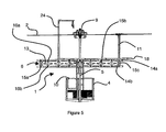
- the figures 4 and 5 illustrate the bridge 6 in horizontal position, that is to say substantially parallel to the platform 4 and the cable 2.
- horizontal means preferably a plane perpendicular to the vertical, the vertical being parallel to the direction of gravity land given for example by a plumb line.
- the figure 6 allows to visualize the position that takes the gateway 6 at the level of a pylon 3.
- the elongate structure, oriented parallel to the cable 2 allows the maintenance operator 12 to access the various rollers 8 of the pylon 3 by moving along the bridge 6 along its longitudinal axis A1.
- the bridge 6 has steps 13 arranged to remain horizontal regardless of the degree of pivoting of the bridge 6 relative to the horizontal. These steps 13 are as illustrated in figures 2 and 6 , offset along the longitudinal axis A1 of the bridge 6.
- the bridge 6 is horizontal and the steps 13 are aligned in the same plane parallel to the horizontal, whereas figures 2 and 3 the bridge 6 is oblique and the steps 13 form a staircase leading from the low end to the high end of the bridge 6.
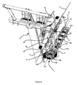
- the bridge 6 comprises two frames 14a, 14b elongated in the direction of movement of the vehicle 1.
- the elongated frames 14a, 14b are pivotally mounted on the hanger 5 respectively according to two parallel pivot axes and offset along the hanger 5 for forming a deformable parallelogram depending on the degree of pivoting of the bridge 6 with respect to the hanger 5.
- a frame 14a, 14b comprises in the same plane two longitudinal uprights oriented along the axis A1 of the bridge 6, these two longitudinal uprights are connected by transverse posts at their proximal ends.
- the longitudinal uprights are perpendicular to the transverse uprights.
- Frames 14a, 14b are preferably located in two parallel planes.
- the parallelogram shape is in particular given by a section of the bridge 6 in a plane perpendicular to the plane formed by a frame and parallel to the axis A1, that is to say to the direction of movement of the maintenance vehicle. 1
- the bridge 6 has a generally rectangular shape
- the gateway 6 has another form of parallelogram. This form of parallelogram makes possible the use of several steps 13 able to remain horizontal regardless of the inclination of the bridge 6.
- the bridge 6 comprises spacers 15a, 15b, 15c.
- Each spacer 15a, 15b, 15c comprises a first end 16a pivotally mounted on two opposite longitudinal uprights of one of the frames 14a and a second end 16b pivotally mounted on two opposite longitudinal uprights of the other frame 14b.
- These spacers allow the frames 14a, 14b to always form a parallelogram regardless of the degree of inclination of the bridge 6 by maintaining said parallel frames 14a, 14b.
- a plane passing through the axis of pivoting of its first end and by the axis of pivoting of its second end is parallel to the vertical.
- the spacers 15a, 15b, 15c may comprise two end spacers 15a, 15c each arranged at a longitudinal end of the bridge 6, and intermediate spacers 15b each provided with a plate to form a step 13.
- the plate is, preferably, perpendicular to the plane comprising the axes of pivoting of the first end and the second end of the intermediate spacer 15b.
- the guide rod 11 is preferably attached to one of the end spacers 15a, 15c. On the Figures 2 to 6 , the guide rod 11 is fixed to the end spacer 15c.
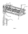
- the hanger 5 comprises a main rod passing through the two frames 14a, 14b.
- the main stem is secant to the planes formed by the frames 14a, 14b and passes between the two longitudinal and transverse amounts of each frame.
- two fastening elements 17a, 17b are fixed on either side of the main rod, each fastening element 17a, 17b cooperating, by associated pivot links, with a longitudinal amount of each frame (14a, 14b).
- the figure 8 illustrates in more detail how the bridge is pivotally mounted on the hanger 5 by the use of fasteners 17a, 17b.
- the upper frame 14a is mounted on the one hand by a pivot connection on the fastening element 17a at its first longitudinal upright 6a and on the other hand by a pivot connection on the fastening element 17b at the its second longitudinal amount 6b opposite the first longitudinal amount 6a, these two pivot links have the same pivot axis P 1 .
- the lower frame 14b is mounted on the one hand by a pivot connection on the fastening element 17a at its first longitudinal upright 6c, and on the other hand by a pivot connection on the fastening element. 17b at its second longitudinal amount 6d opposite the first longitudinal amount 6c, these two pivot links have the same pivot axis P 2 .
- the pivot axes P 1 and P 2 are parallel and delimit a vertical plane.
- a portion 5a of the hanger 5 has, preferably, an arcuate shape for delimiting a first support section T 1 of the nacelle 4.
- the section T 1 is horizontal and perpendicular to the direction of travel of the vehicle of maintenance.
- This portion 5a also delimits a second section T 2 connecting the first section T 1 to the fastener 9.
- the second section T 2 is substantially vertical.
- the bridge 6 is mounted on the hanger 5 at the second section T 2 . In other words, in general, the bridge 6 is located on the hanger 5 between the nacelle 4 and the fastener 9. Therefore, it is possible to provide means for passage of the nacelle 4 to the bridge 6, these means of passage can be in the form of a scale 7.
- the gateway 6 is not located below the cable 2 but is shifted from the cable 2 relative to the vertical so as to facilitate access to the rollers 8 of a tower 3 on which the cable 2 will be supported.
- the maintenance vehicle 1 can be coupled to the cable 2 so that the gateway 6 is distal from the pylon 3 supporting the cable 2.
- a vertical plane passing through the cable 2 parallel to said cable 2 the pylon 3 is located on the left of said vertical plane, and the bridge 6 is located on the right of said vertical plane. According to figure 6 , starting from the pylon 3, one finds shifted in the same direction the nacelle 4 then the bridge 6.
- the bridge 6 preferably comprises a retractable rail 18.
- a railing 18 can then occupy an expanded state forming a railing as on the figure 6 , and a storage state in which the guardrail 18 is retracted towards a platform of the bridge 6 as shown in FIGS. figures 4 and 5 .
- Platform refers to the gateway structure at which the operator can walk.
- This railing 18 is preferably mounted along the bridge on its longitudinal side opposite the nacelle 4, that is to say the side of the bridge 6 distal of the pylon 3 on the figure 6 .
- the maintenance vehicle comprises control means for moving from the deployed state to the retracted state of the guardrail 18 and vice versa.
- control means are accessible from the nacelle 4.
- the maintenance operator can deploy the railing 18.
- the guardrail 18 may comprise a handrail 18a ( figure 10 ) and uprights 18b integral on the one hand of the handrail and on the other hand a frame 14a of the bridge. Each upright 18b is connected on the one hand by a pivot connection to the frame 14a, and on the other hand by a pivot connection to the handrail 18a.
- the control means can be implemented by a cylindrical rod 19 traversing laterally the bridge 6.
- the cylindrical rod 19 comprises an actuable end of the platform 4 so as to implement rotation of the cylindrical rod 19, and has at its end opposite the nacelle 4 a member 20 fixed on the rod 19, and extending perpendicularly to the cylindrical rod 19.
- This member 20 has at its distal end of the rod 19 a lug 21.
- the lug 21 slides in a slot 22 of a return arm 23 fixed to one of the uprights 18b of the railing.
- the return arm 23 is arranged so that the rotation of the cylindrical rod 19 causes a movement of the lug 21 which moves in the lumen 22 of the return arm 23 while transmitting to the return arm 23 a driving movement.
- the uprights 18b take advantage of the pivoting axes of the end of the intermediate struts 15b to be pivotally mounted thereon. This makes it possible, among other things, to avoid the duplication of the pivot axes at the level of the frame 14a in order to lighten the weight of the maintenance vehicle.
- the distance between the steps of the bridge and the cable is adjusted so that the cable is at the height of the maintenance operator when the latter is on the bridge.
- the gateway 6 may further include tooling.
- the tooling comprises a mast 24 equipped with a pulley.
- the skilled person can add any type of tools useful for the maintenance of pebbles of a pylon.
- the installation can be of any type.
- the vehicle is fixed to the cable 2 which is tractor.
Landscapes
- Engineering & Computer Science (AREA)
- Transportation (AREA)
- Mechanical Engineering (AREA)
- Bridges Or Land Bridges (AREA)
- Ladders (AREA)
- Forklifts And Lifting Vehicles (AREA)
Abstract
Description
- L'invention est relative à une installation de transport par câble aérien pour se déplacer le long d'une voie, l'installation comportant un véhicule de maintenance muni :
- d'une nacelle montée sur une suspente reliée au câble par une attache,
- d'une passerelle montée sur la suspente.
- Une installation de transport par câble aérien comprend classiquement une pluralité de véhicules de transport suspendus à au moins un câble aérien principal pouvant être de type tracteur, porteur, ou tracteur-porteur. Les véhicules se déplacent généralement le long de deux voies respectivement aller et retour. Une telle installation peut être constituée par un télécabine classique où l'ensemble des véhicules de transport cheminent tous sur une trajectoire identique en boucle fermée, ou bien par un téléphérique, ou bien encore par une installation de type va et vient, ou de type va ou vient.
- Classiquement le câble aérien permet aux véhicules de se rendre d'une station de départ à une station d'arrivée. Entre ces stations, le câble est maintenu à distance du sol par l'intermédiaire de pylônes permettant notamment d'adapter la pente du câble au relief parcouru par l'installation.
- Des opérations de maintenance peuvent être nécessaires aux niveau de galets de ces pylônes. Il résulte donc un besoin d'accéder au sommet de ces pylônes. Pour cela, les pylônes sont en général équipés d'une échelle reliant une passerelle disposée au sommet des pylônes, et agencée pour permettre l'accès aux galets.
- La maintenance utilisant les échelles est fastidieuse, et certains pylônes sont difficiles d'accès.
- Pour remédier aux problématiques d'accès des pylônes, il a été développé des véhicules spécifiques de maintenance aptes à se déplacer par accouplement au câble mobile.
- La
figure 1 illustre un tel véhicule de maintenance 1 relié à un câble 2 au niveau d'un pylône 3. Le véhicule de maintenance 1 comporte une nacelle 4, et une suspente 5 montée d'une part sur la nacelle 4 et d'autre part au câble 2 par une attache 9. Une passerelle 6 est fixée sur la suspente 5. Ainsi, entre deux pylônes, l'opérateur chargé de la maintenance est sécurisé dans la nacelle 4. Lors de l'arrivée du véhicule de maintenance 1 à un pylône 3, ledit véhicule 1 est stoppé, l'opérateur peut alors monter sur la passerelle 6, par exemple en empruntant une échelle 7. La passerelle 6 lui donne accès aux parties mécaniques du pylône 3, comme par exemple les galets 8 de pylône qui supportent le câble 2. - Souvent, les pylônes comportent comme illustré à la
figure 1 une pluralité de galets 8, et la passerelle 6 du véhicule de maintenance 1 ne permet pas de rendre tous ces galets accessibles. Dès lors, pour vérifier tous les galets 8 d'un même pylône 3, il est nécessaire de déplacer plusieurs fois le véhicule de maintenance. - L'objet de l'invention consiste à réaliser une installation équipée d'un véhicule facilitant les opérations de maintenance de l'installation préférablement au niveau des pylônes.
- On tend vers cet objet en ce que le véhicule de maintenance comporte une tige de guidage fixée à la passerelle par une de ses extrémités, et reliée au câble par son extrémité opposée, et en ce que la passerelle a une structure s'étendant dans la direction de déplacement du véhicule de maintenance, et est montée à pivotement sur la suspente pour former une bascule articulée.
- Selon un développement, la passerelle comporte des marches agencées pour rester à l'horizontale quel que soit le degré de pivotement de la passerelle par rapport à l'horizontale.
- Selon un mode de réalisation, la passerelle comporte deux cadres allongés dans la direction de déplacement du véhicule de maintenance, les cadres allongés étant montés à pivotement sur la suspente respectivement selon deux axes de pivotement parallèles et décalés le long de la suspente, lesdits cadres étant agencés pour former un parallélogramme déformable en fonction du degré de pivotement de la passerelle par rapport à la suspente.
- Selon une mise en oeuvre du mode de réalisation, la passerelle comporte des entretoises, comprenant chacune une première extrémité montée à pivotement sur deux montants longitudinaux opposés de l'un des cadres et une seconde extrémité montée à pivotement sur deux montants longitudinaux opposés de l'autre cadre.
- Selon un perfectionnement, les entretoises comportent deux entretoises d'extrémité disposées chacune à une extrémité longitudinale de la passerelle et des entretoises intermédiaires munie chacune d'un plateau pour former une marche, la tige de guidage étant fixée à l'une des entretoises d'extrémité.
- Selon une mise en oeuvre particulière de l'installation, la suspente comporte une tige principale traversant les deux cadres, deux éléments de fixation étant fixés de part et d'autre de la tige principale, chaque élément de fixation coopérant, par des liaisons pivots associées, avec un montant longitudinal de chaque cadre.
- Selon un perfectionnement, la passerelle est équipée d'une rambarde apte à occuper un état déployé formant garde-corps, et un état de rangement dans lequel la rambarde est rétractée en direction d'une plateforme de la passerelle.
- D'autres avantages et caractéristiques ressortiront plus clairement de la description qui va suivre de modes particuliers de réalisation de l'invention donnés à titre d'exemples non limitatifs et représentés aux dessins annexés, dans lesquels :
- la
figure 1 représente une installation selon l'art antérieur, - la
figure 2 illustre une vue en perspective d'un véhicule de maintenance dont la passerelle est en position oblique, - la
figure 3 illustre une vue de côté du véhicule de lafigure 2 , ladite vue étant réalisée dans un plan vertical sensiblement parallèle à la direction de déplacement du véhicule, - la
figure 4 illustre une vue en perspective d'un véhicule de maintenance dont la passerelle est en position horizontale, - la
figure 5 illustre une vue de côté du véhicule de lafigure 4 , ladite vue étant réalisée dans un plan vertical sensiblement parallèle à la direction de déplacement du véhicule, - la
figure 6 illustre le véhicule de maintenance en position de maintenance au niveau d'un pylône de l'installation. - la
figure 7 illustre une vue du véhicule de maintenance perpendiculairement au sens de déplacement dudit véhicule, - la
figure 8 illustre une vue en coupe perpendiculairement au sens de déplacement du véhicule de maintenance représentant schématiquement le montage à pivotement de la passerelle sur la suspente, - la
figure 9 illustre une vue du véhicule de maintenance centrée sur les moyens de commande permettant de déployer une rambarde de la passerelle, - la
figure 10 illustre une autre vue du véhicule de maintenance centrée sur les moyens de commande permettant de déployer la rambarde. - L'installation décrite ci-après diffère de l'art antérieur en ce qu'elle permet d'augmenter l'espace de travail d'un opérateur de maintenance au niveau de la passerelle.
- Sur les
figures 2 à 6 , l'installation de transport par câble 2 aérien, de préférence tracteur, pour se déplacer le long d'une voie, comporte un véhicule de maintenance 1 muni d'une nacelle 4 montée sur une suspente 5 reliée au câble 2 de préférence par une attache 9. L'attache 9 est, de préférence, fixe ou débrayable par rapport au câble 2. - La nacelle 4 est destinée à porter de manière sécurisée un ou plusieurs opérateurs de maintenance lors du déplacement du véhicule de maintenance 1. Pour cela, la nacelle 4 comporte, de préférence, un garde-corps 10.
- Le véhicule de maintenance 1 comporte en outre une passerelle 6 montée sur la suspente 5. Cette passerelle 6 a une structure s'étendant dans la direction de déplacement du véhicule de maintenance 1. Autrement dit, la passerelle 6 est allongée dans la direction de déplacement du véhicule de maintenance 1. Cet allongement permet entre autres de procurer à l'opérateur de maintenance un espace de travail plus vaste que dans l'art antérieur et d'accéder à plusieurs, voir à tous les galets 8 d'un pylône 3 sans avoir à déplacer le véhicule de maintenance 1 lorsque ce dernier est arrêté au niveau d'un pylône 3 (
figure 6 ). - L'allongement de l'espace de travail entraîne d'une part un risque de contact entre la passerelle 6 et le câble 2 notamment lors du passage au niveau d'un pylône 3 qui peut, en fonction de l'évolution du relief au sol, changer la pente du câble 2. D'autre part, afin de travailler confortablement au niveau d'un pylône 3, il est préférable que, lors du déplacement de l'opérateur le long de la passerelle 6, ce dernier soit toujours à hauteur constante par rapport aux galets 8 pour travailler. Lorsque la passerelle 6 est horizontale, et le câble 2 porté par les galets 8 est oblique, il est impossible pour un opérateur de maintenance debout sur la passerelle 6 de travailler à hauteur constante.
- Il résulte donc un besoin d'adapter l'inclinaison de la passerelle 6 à la pente du câble 2. Pour répondre à ce besoin, le véhicule comporte une tige de guidage 11 fixée à la passerelle 6 par une de ses extrémités. L'autre extrémité de la tige de guidage 11, opposée à l'extrémité fixée à la passerelle 6, est reliée au câble 2. De préférence, la tige de guidage 11 est reliée au câble 2 par une attache associée, de préférence de manière fixe ou débrayable. La passerelle 6 est montée à pivotement sur la suspente 5 pour former une bascule articulée. Ainsi, par l'intermédiaire de la tige de guidage 11, la passerelle 6 sera orientée selon l'inclinaison du câble 2, ce qui réduira les risques de venir frapper le câble 2 au niveau d'une rupture de pente du câble 2, et permettra un accès plus aisé aux galets 8 du pylône 3 (
figure 6 ). Ceci peut être rendu possible grâce à l'utilisation d'un axe de pivotement de la passerelle perpendiculaire à la direction de déplacement du véhicule de maintenance 1. - La passerelle 6 est, de préférence, disposée entre la nacelle 4 et l'attache 9.
- Les
figures 2 et3 illustrent le véhicule de maintenance 1 accouplé à un câble 2 de pente oblique. La passerelle 6 est sensiblement parallèle au câble 2 grâce à la tige de guidage 11 qui permet, de préférence, de maintenir la passerelle 6 à équidistance du câble 2. - Les
figures 4 et5 illustrent la passerelle 6 en position horizontale, c'est-à-dire sensiblement parallèle à la nacelle 4 et au câble 2. - Dans le présent texte, par horizontal, on entend de préférence un plan perpendiculaire à la verticale, la verticale étant parallèle à la direction de pesanteur terrestre donnée par exemple par un fil à plomb.
- La
figure 6 permet de visualiser la position que prend la passerelle 6 au niveau d'un pylône 3. Sur cettefigure 6 , on voit clairement que la structure allongée, orientée parallèlement au câble 2, permet à l'opérateur de maintenance 12 d'accéder aux différents galets 8 du pylône 3 en se déplaçant le long de la passerelle 6 selon son axe longitudinal A1. - Selon un perfectionnement permettant de faciliter le travail de l'opérateur de maintenance 12 et d'assurer sa sécurité, la passerelle 6 comporte des marches 13 agencées pour rester à l'horizontale quel que soit le degré de pivotement de la passerelle 6 par rapport à l'horizontale. Ces marches 13 sont comme illustrées aux
figures 2 et6 , décalées le long de l'axe longitudinal A1 de la passerelle 6. - Sur les
figures 4 et5 , la passerelle 6 est horizontale et les marches 13 sont alignées dans un même plan parallèle à l'horizontale, alors qu'auxfigures 2 et3 la passerelle 6 est oblique et les marches 13 forment un escalier menant de l'extrémité basse à l'extrémité haute de la passerelle 6. - Selon une variante de mise en oeuvre illustrée aux
figures 2 à 6 , la passerelle 6 comporte deux cadres 14a, 14b allongés dans la direction de déplacement du véhicule 1. Les cadres 14a, 14b allongés sont montés à pivotement sur la suspente 5 respectivement selon deux axes de pivotement parallèles et décalés le long de la suspente 5 pour former un parallélogramme déformable en fonction du degré de pivotement de la passerelle 6 par rapport à la suspente 5. Un cadre 14a, 14b comporte dans un même plan deux montants longitudinaux orientés selon l'axe A1 de la passerelle 6, ces deux montants longitudinaux sont reliés par des montants transversaux à leurs extrémités proximales. De préférence, les montants longitudinaux sont perpendiculaires aux montants transversaux. Les cadres 14a, 14b sont, de préférence, situés dans deux plans parallèles. La forme de parallélogramme est en particulier donnée par une coupe de la passerelle 6 selon un plan perpendiculaire au plan formé par un cadre et parallèle à l'axe A1 c'est-à-dire à la direction de déplacement du véhicule de maintenance. 1 Ainsi, sur lafigure 5 , la passerelle 6 a une forme générale rectangulaire, et sur lafigure 3 la passerelle 6 a une autre forme de parallélogramme. Cette forme de parallélogramme rend possible l'utilisation de plusieurs marches 13 aptes à rester horizontales quelle que soit l'inclinaison de la passerelle 6. - Selon une mise en oeuvre particulière visible notamment aux
figures 2 à 6 , la passerelle 6 comporte des entretoises 15a, 15b, 15c. Chaque entretoise 15a, 15b, 15c comprend une première extrémité 16a montée à pivotement sur deux montants longitudinaux opposés de l'un des cadres 14a et une seconde extrémité 16b montée à pivotement sur deux montants longitudinaux opposés de l'autre cadre 14b. Ces entretoises permettent aux cadres 14a, 14b de toujours former un parallélogramme quel que soit le degré d'inclinaison de la passerelle 6 en maintenant lesdits cadres 14a, 14b parallèles. De préférence, pour chaque entretoise 15a, 15b, 15c, un plan passant par l'axe de pivotement de sa première extrémité et par l'axe de pivotement de sa seconde extrémité est parallèle à la verticale. - Les entretoises 15a, 15b, 15c peuvent comporter deux entretoises d'extrémités 15a, 15c disposées chacune à une extrémité longitudinale de la passerelle 6, et des entretoises intermédiaires 15b chacune munie d'un plateau pour former une marche 13. Le plateau est, de préférence, perpendiculaire au plan comprenant les axes de pivotement de la première extrémité et de la seconde extrémité de l'entretoise intermédiaire 15b. La tige de guidage 11 est, de préférence, fixée à l'une des entretoises d'extrémité 15a, 15c. Sur les
figures 2 à 6 , la tige de guidage 11 est fixée à l'entretoise d'extrémité 15c. - Selon une mise en oeuvre, la suspente 5 comporte une tige principale traversant les deux cadres 14a, 14b. Autrement dit, la tige principale est sécante aux plans formés par les cadres 14a, 14b et passe entre les deux montants longitudinaux et transversaux de chaque cadre. Comme illustré aux
figures 2 et7 , deux éléments de fixation 17a, 17b sont fixés de part et d'autre de la tige principale, chaque élément de fixation 17a, 17b coopérant, par des liaisons pivots associées, avec un montant longitudinal de chaque cadre (14a, 14b). - La
figure 8 permet d'illustrer plus en détail comment la passerelle est montée à pivotement sur la suspente 5 par l'utilisation d'éléments de fixation 17a, 17b. En fait, le cadre supérieur 14a est monté d'une part par une liaison pivot sur l'élément de fixation 17a au niveau de son premier montant longitudinal 6a et d'autre part par une liaison pivot sur l'élément de fixation 17b au niveau de son second montant longitudinal 6b opposé au premier montant longitudinal 6a, ces deux liaisons pivots comportent un même axe de pivotement P1. De la même manière, le cadre inférieur 14b est monté d'une part par une liaison pivot sur l'élément de fixation 17a au niveau de son premier montant longitudinal 6c, et d'autre part par une liaison pivot sur l'élément de fixation 17b au niveau de son second montant longitudinal 6d opposé au premier montant longitudinal 6c, ces deux liaisons pivots comportent un même axe de pivotement P2. De préférence, les axes de pivotement P1 et P2 sont parallèles et délimitent un plan vertical. - Comme illustré à la
figure 7 , une portion 5a de la suspente 5 a, de préférence, une forme arquée permettant de délimiter un premier tronçon T1 de support de la nacelle 4. De préférence, le tronçon T1 est horizontal et perpendiculaire à la direction de déplacement du véhicule de maintenance. Cette portion 5a permet aussi de délimiter un second tronçon T2 reliant le premier tronçon T1 à l'attache 9. De préférence, le second tronçon T2 est sensiblement vertical. La passerelle 6 est montée sur la suspente 5 au niveau du second tronçon T2. Autrement dit, de manière générale, la passerelle 6 est située sur la suspente 5 entre la nacelle 4 et l'attache 9. Dès lors, il est possible de prévoir des moyens de passage de la nacelle 4 à la passerelle 6, ces moyens de passage peuvent se présenter sous la forme d'une échelle 7. - De préférence, la passerelle 6 n'est pas située en dessous du câble 2 mais est décalée du câble 2 par rapport à la verticale de sorte à faciliter l'accès aux galets 8 d'un pylône 3 sur lesquels le câble 2 sera supporté. Ainsi, sur la
figure 6 , le véhicule de maintenance 1 peut être accouplé au câble 2 pour que la passerelle 6 soit distale du pylône 3 supportant le câble 2. En prenant un plan vertical passant par le câble 2 parallèlement audit câble 2, le pylône 3 se situe sur la gauche dudit plan vertical, et la passerelle 6 se situe sur la droite dudit plan vertical. Selon lafigure 6 , à partir du pylône 3, on retrouve décalés dans une même direction la nacelle 4 puis la passerelle 6. - Afin d'améliorer la sécurité de l'opérateur de maintenance 12 illustré à la
figure 6 , la passerelle 6 comporte de préférence une rambarde 18 rétractable. Une telle rambarde 18 peut alors occuper un état déployé formant garde-corps comme sur lafigure 6 , et un état de rangement dans lequel la rambarde 18 est rétractée en direction d'une plateforme de la passerelle 6 comme illustré auxfigures 4 et5 . Par plateforme, on entend la structure de la passerelle au niveau de laquelle l'opérateur peut marcher. Cette rambarde 18 est, de préférence, montée le long de la passerelle sur son côté longitudinal opposé à la nacelle 4, c'est-à-dire le côté de la passerelle 6 distal du pylône 3 sur lafigure 6 . - De préférence, le véhicule de maintenance comporte des moyens de commande permettant de passer de l'état déployé à l'état rétracté de la rambarde 18 et inversement. Ces moyens de commande sont accessibles à partir de la nacelle 4. Ainsi, avant de monter sur la passerelle 6, l'opérateur de maintenance peut déployer la rambarde 18.
- Sur les
figures 9 et10 la rambarde 18 peut comporter une main courante 18a (figure 10 ) et des montants 18b solidaires d'une part de la main courante et d'autre part d'un cadre 14a de la passerelle. Chaque montant 18b est relié d'une part grâce à une liaison pivot au cadre 14a, et d'autre part par une liaison pivot à la main-courante 18a. - Les moyens de commande peuvent être mis en oeuvre par une tige cylindrique 19 traversant latéralement la passerelle 6. La tige cylindrique 19 comporte une extrémité actionnable de la nacelle 4 de sorte à mettre en rotation la tige cylindrique 19, et comporte à son extrémité opposée à la nacelle 4 un organe 20 fixé sur la tige 19, et s'étendant perpendiculairement à la tige cylindrique 19. Cet organe 20 comporte à son extrémité distale de la tige 19 un ergot 21. L'ergot 21 coulisse dans une lumière 22 d'un bras de rappel 23 fixé à l'un des montants 18b de la rambarde. Le bras de rappel 23 est agencé de sorte que la mise en rotation de la tige cylindrique 19 entraîne un mouvement de l'ergot 21 qui se déplace dans la lumière 22 du bras de rappel 23 tout en transmettant au bras de rappel 23 un mouvement entraînant le déploiement de la rambarde 18 lorsque cette dernière est en position rétractée, ou le rangement de la rambarde 18 lorsque cette dernière est en position déployée.
- Sur la
figure 10 , on voit que les montants 18b profitent des axes de pivotement de l'extrémité des entretoises intermédiaires 15b pour y être montés à pivotement. Ceci permet entre autres d'éviter la duplication des axes de pivotement au niveau du cadre 14a pour alléger le poids du véhicule de maintenance. - Bien entendu, l'homme du métier est apte à mettre en oeuvre tout type de rambarde apte à se déployer et à se rétracter à l'aide de moyens de commande à distance.
- De préférence, la distance entre les marches de la passerelle et le câble est ajustée de sorte que le câble soit à la hauteur de l'opérateur de maintenance lorsque ce dernier est sur la passerelle.
- La passerelle 6 peut en outre comporter un outillage. Sur les
figures 4 à 7 l'outillage comporte un mât 24 équipé d'une poulie. Bien entendu, l'homme du métier pourra rajouter tout type d'outillage utile à la maintenance des galets d'un pylône. - Comme visé dans l'art antérieur l'installation peut être de tout type. De préférence, entre une station amont et une station aval de l'installation, le véhicule est fixé au câble 2 qui est tracteur.
Claims (7)
- Installation de transport par câble (2) aérien pour se déplacer le long d'une voie, comportant un véhicule de maintenance (1) muni :- d'une nacelle (4) montée sur une suspente (5) reliée au câble (2) par une attache (9),- d'une passerelle (6) montée sur la suspente (5),
caractérisée en ce que le véhicule de maintenance (1) comporte une tige de guidage (11) fixée à la passerelle (6) par une de ses extrémités, et reliée au câble (2) par son extrémité opposée, et en ce que la passerelle (6) a une structure s'étendant dans la direction de déplacement du véhicule de maintenance (1), et est montée à pivotement sur la suspente (5) pour former une bascule articulée. - Installation selon la revendication 1, caractérisée en ce que la passerelle (6) comporte des marches (13) agencées pour rester à l'horizontale quel que soit le degré de pivotement de la passerelle (6) par rapport à l'horizontale.
- Installation selon la revendication 2, caractérisée en ce que la passerelle (6) comporte deux cadres (14a, 14b) allongés dans la direction de déplacement du véhicule de maintenance (1), les cadres (14a, 14b) allongés étant montés à pivotement sur la suspente (5) respectivement selon deux axes de pivotement parallèles et décalés le long de la suspente (5), lesdits cadres (14a, 14b) étant agencés pour former un parallélogramme déformable en fonction du degré de pivotement de la passerelle (6) par rapport à la suspente (5).
- Installation selon la revendication 3, caractérisée en ce que la passerelle (6) comporte des entretoises (15a, 15b, 15c), comprenant chacune une première extrémité (16a) montée à pivotement sur deux montants longitudinaux opposés de l'un des cadres (14a, 14b) et une seconde extrémité (16b) montée à pivotement sur deux montants longitudinaux opposés de l'autre cadre (14a, 14b).
- Installation selon la revendication 4, caractérisée en ce que les entretoises (15a, 15b, 15c) comportent deux entretoises d'extrémité (15a, 15c) disposées chacune à une extrémité longitudinale de la passerelle (6) et des entretoises intermédiaires (15b) munie chacune d'un plateau pour former une marche (13), la tige de guidage (11) étant fixée à l'une des entretoises d'extrémité (15a, 15c).
- Installation selon l'une quelconque des revendications 3 à 5, caractérisée en ce que la suspente (5) comporte une tige principale traversant les deux cadres (14a, 14b), deux éléments de fixation (17a, 17b) étant fixés de part et d'autre de la tige principale, chaque élément de fixation (17a, 17b) coopérant, par des liaisons pivots associées, avec un montant longitudinal de chaque cadre (14a, 14b).
- Installation selon l'une quelconque des revendications précédentes, caractérisée en ce que la passerelle (6) est équipée d'une rambarde (18) apte à occuper un état déployé formant garde-corps, et un état de rangement dans lequel la rambarde (18) est rétractée en direction d'une plateforme de la passerelle (6).
Applications Claiming Priority (1)
| Application Number | Priority Date | Filing Date | Title |
|---|---|---|---|
| FR1100875A FR2972986B1 (fr) | 2011-03-23 | 2011-03-23 | Installation de transport par cable aerien munie d'un vehicule de maintenance |
Publications (2)
| Publication Number | Publication Date |
|---|---|
| EP2502799A1 true EP2502799A1 (fr) | 2012-09-26 |
| EP2502799B1 EP2502799B1 (fr) | 2013-11-20 |
Family
ID=45819166
Family Applications (1)
| Application Number | Title | Priority Date | Filing Date |
|---|---|---|---|
| EP12354016.3A Active EP2502799B1 (fr) | 2011-03-23 | 2012-03-05 | Installation de transport par câble aérien munie d'un véhicule de maintenance |
Country Status (6)
| Country | Link |
|---|---|
| US (1) | US8578858B2 (fr) |
| EP (1) | EP2502799B1 (fr) |
| KR (1) | KR101886436B1 (fr) |
| CN (1) | CN102689633B (fr) |
| CA (1) | CA2770974C (fr) |
| FR (1) | FR2972986B1 (fr) |
Cited By (4)
| Publication number | Priority date | Publication date | Assignee | Title |
|---|---|---|---|---|
| WO2018122790A1 (fr) * | 2016-12-29 | 2018-07-05 | Scotech Gmbh | Nacelle de maintenance et procédé de maintenance d'un téléphérique |
| AT522165B1 (de) * | 2019-04-02 | 2020-09-15 | Innova Patent Gmbh | Seilbahnstütze mit einer Überstiegsvorrichtung |
| WO2021239296A1 (fr) * | 2020-05-27 | 2021-12-02 | Innova Patent Gmbh | Véhicule de téléphérique ayant un appareil de croisement |
| WO2025215323A1 (fr) * | 2024-04-12 | 2025-10-16 | Mnd France | Dispositif d'assemblage d'un balancier |
Families Citing this family (15)
| Publication number | Priority date | Publication date | Assignee | Title |
|---|---|---|---|---|
| FR2972986B1 (fr) * | 2011-03-23 | 2013-04-26 | Pomagalski Sa | Installation de transport par cable aerien munie d'un vehicule de maintenance |
| FR3003222B1 (fr) * | 2013-03-14 | 2016-09-09 | Sommital | Vehicule de remontee mecanique et installation comprenant ce vehicule |
| FR3006653B1 (fr) * | 2013-06-05 | 2016-07-29 | Pomagalski Sa | Dispositif de maintenance d'une installation de transport par cable aerien, notamment un telesiege ou telecabine |
| AT514516B1 (de) * | 2013-07-11 | 2015-05-15 | Innova Patent Gmbh | Vorrichtung zum Auswechseln von Rollenbatterien |
| US10461513B2 (en) * | 2014-04-08 | 2019-10-29 | Wall Industries Inc. | Apparatus for moving a line cart along a cable |
| CN104124628B (zh) * | 2014-07-25 | 2017-01-18 | 国家电网公司 | 一种组合式检修平台 |
| US9579578B2 (en) * | 2014-09-16 | 2017-02-28 | Ronald Chasteen | Zip line trolley retriever system |
| CN105406389B (zh) * | 2015-10-23 | 2017-11-07 | 国网江苏省电力公司无锡供电公司 | 多线巡检电动飞车 |
| FR3050424B1 (fr) * | 2016-04-21 | 2019-06-28 | Poma | Installation et procede de transport par cable aerien |
| CN106618365B (zh) * | 2017-01-25 | 2022-01-04 | 百事特设备租赁(上海)股份有限公司 | 一种擦窗机的伸缩吊具机构 |
| CN108519245B (zh) * | 2018-04-24 | 2021-01-12 | 华北水利水电大学 | 一种缆索检修设备性能试验装置及测试方法 |
| WO2021083184A1 (fr) * | 2019-10-31 | 2021-05-06 | 江苏飞梭智行设备有限公司 | Appareil de changement de voie ferrée, véhicule et système de transport ferroviaire anti-déraillement |
| CN111926640B (zh) * | 2020-08-14 | 2021-09-28 | 北京中建空列集团有限公司 | 可移动的悬挂式空中列车轨道检修系统 |
| DE102021110649B3 (de) * | 2021-04-26 | 2022-06-23 | Pentanova Cs Gmbh | Wartungsshuttle für eine Elektrohängebahn |
| CN115733089B (zh) * | 2022-11-18 | 2024-09-20 | 青海送变电工程有限公司 | 用于电缆维护的导线飞车 |
Citations (2)
| Publication number | Priority date | Publication date | Assignee | Title |
|---|---|---|---|---|
| DE3641778C1 (en) * | 1986-12-06 | 1987-09-17 | Manfred Dipl-Ing Grassl | Apparatus for travelling on ropes or cables of structures, in particular for travelling on the bridge cables of suspension and cable-stayed bridges |
| EP2028074A1 (fr) * | 2007-08-20 | 2009-02-25 | Pomagalski | Véhicule d'intervention le long d'un câble aérien d'une installation de remontée mécanique |
Family Cites Families (27)
| Publication number | Priority date | Publication date | Assignee | Title |
|---|---|---|---|---|
| US3237718A (en) * | 1964-05-13 | 1966-03-01 | Ederer Corp | Two-sided suspension system for staging |
| US3710726A (en) * | 1970-04-27 | 1973-01-16 | H Buchholz | Cableway |
| US3702124A (en) * | 1970-07-20 | 1972-11-07 | Stanley E Highland | Traversing skips |
| BE790482A (fr) * | 1971-11-16 | 1973-02-15 | Patin Pierre | Transporteur du genre telepherique a cable porteur |
| DE2553746C3 (de) * | 1974-12-10 | 1980-01-17 | Gerhard Dietlikon Mueller (Schweiz) | Tragsystem für eine Hängebahn |
| US3945462A (en) * | 1975-06-18 | 1976-03-23 | Griswold James D | Hanger brackets |
| US4163480A (en) * | 1978-02-21 | 1979-08-07 | Highland Stanley E | Line travelling skips |
| US4234055A (en) * | 1978-09-25 | 1980-11-18 | Beeche Gregory L | Mobile suspension scaffold system |
| US4253548A (en) * | 1979-10-31 | 1981-03-03 | Beeche Gregory L | Folding scaffold system |
| USD274230S (en) * | 1981-07-23 | 1984-06-12 | TI Reynolds Limited | Cable supported personnel carrier |
| USD274320S (en) * | 1981-11-05 | 1984-06-19 | TI Reynolds Limited | Cable supported personnel carrier |
| US4478312A (en) * | 1982-09-30 | 1984-10-23 | Kurtgis Michael P | System and portable cage for servicing power transmission lines |
| FR2547850B1 (fr) * | 1983-06-21 | 1988-05-06 | Pomagalski Sa | Passerelle d'acces notamment aux balanciers d'une installation de transport a cable aerien |
| CH656357A5 (fr) * | 1983-07-04 | 1986-06-30 | Vevey Atel Const Mec | Vehicule motorise suspendu. |
| US4705140A (en) * | 1987-03-19 | 1987-11-10 | Metropolitan Stevedore Company | Safety cage for attending to locks on cargo containers |
| DE3715904C1 (de) * | 1987-05-13 | 1988-08-11 | Xaver Lipp | Selbstangetriebener Wagen zum Fahren laengs eines ummantelten Seiles |
| CH693091A5 (de) * | 1994-11-02 | 2003-02-28 | Garaventa Holding Ag | Bergungsfahrzeug für eine Seilbahn. |
| US6189455B1 (en) * | 1999-03-10 | 2001-02-20 | Jta, Inc. | Transport apparatus |
| US6227330B1 (en) * | 1999-07-15 | 2001-05-08 | Mark A. Preusser | Support structure for suspending a work surface below a girder |
| AU2104101A (en) * | 1999-12-14 | 2001-06-25 | Yury Sherman | System for supporting substantially rigid linear structures |
| AT500573B1 (de) * | 2002-09-03 | 2007-01-15 | Innova Patent Gmbh | Seilbahnanlage mit einem trag- und förderseil und mit einer vielzahl von an dieses ankuppelbaren sesseln |
| US6817444B1 (en) * | 2002-09-10 | 2004-11-16 | George Shinas | Suspended work platform |
| US7743444B2 (en) * | 2004-06-09 | 2010-06-29 | Incorporated Administrative Agency Public Works Research Institute | Cable stayed suspension bridge making combined use of one-box and two-box girders |
| CA2498870C (fr) * | 2004-12-17 | 2006-01-24 | Structure D'acier Orleans Inc. | Echafaudage volant a cables |
| JP4763495B2 (ja) * | 2006-03-30 | 2011-08-31 | 日本ケーブル株式会社 | 索道の救助装置 |
| US7552685B2 (en) * | 2007-01-30 | 2009-06-30 | Easy Access Systems, Inc. | Apparatus for servicing the main cable of a suspension bridge |
| FR2972986B1 (fr) * | 2011-03-23 | 2013-04-26 | Pomagalski Sa | Installation de transport par cable aerien munie d'un vehicule de maintenance |
-
2011
- 2011-03-23 FR FR1100875A patent/FR2972986B1/fr not_active Expired - Fee Related
-
2012
- 2012-03-05 EP EP12354016.3A patent/EP2502799B1/fr active Active
- 2012-03-05 CA CA2770974A patent/CA2770974C/fr active Active
- 2012-03-16 US US13/422,551 patent/US8578858B2/en active Active
- 2012-03-21 KR KR1020120028701A patent/KR101886436B1/ko active Active
- 2012-03-22 CN CN201210077545.3A patent/CN102689633B/zh active Active
Patent Citations (2)
| Publication number | Priority date | Publication date | Assignee | Title |
|---|---|---|---|---|
| DE3641778C1 (en) * | 1986-12-06 | 1987-09-17 | Manfred Dipl-Ing Grassl | Apparatus for travelling on ropes or cables of structures, in particular for travelling on the bridge cables of suspension and cable-stayed bridges |
| EP2028074A1 (fr) * | 2007-08-20 | 2009-02-25 | Pomagalski | Véhicule d'intervention le long d'un câble aérien d'une installation de remontée mécanique |
Cited By (12)
| Publication number | Priority date | Publication date | Assignee | Title |
|---|---|---|---|---|
| WO2018122790A1 (fr) * | 2016-12-29 | 2018-07-05 | Scotech Gmbh | Nacelle de maintenance et procédé de maintenance d'un téléphérique |
| EP4005899A1 (fr) | 2016-12-29 | 2022-06-01 | SwissReviGondola AG | Procédé d'entretien d'un téléphérique |
| AT522165B1 (de) * | 2019-04-02 | 2020-09-15 | Innova Patent Gmbh | Seilbahnstütze mit einer Überstiegsvorrichtung |
| AT522165A4 (de) * | 2019-04-02 | 2020-09-15 | Innova Patent Gmbh | Seilbahnstütze mit einer Überstiegsvorrichtung |
| WO2020201254A1 (fr) * | 2019-04-02 | 2020-10-08 | Innova Patent Gmbh | Pylône de téléphérique comportant un dispositif de passage |
| CN113727903A (zh) * | 2019-04-02 | 2021-11-30 | 创新专利有限公司 | 带有攀爬设备的索道支架 |
| JP2022527811A (ja) * | 2019-04-02 | 2022-06-06 | インノヴァ・パテント・ゲゼルシャフト・ミット・ベシュレンクテル・ハフツング | 乗り移り装置を有するロープウェイ支柱 |
| CN113727903B (zh) * | 2019-04-02 | 2023-11-24 | 创新专利有限公司 | 带有攀爬设备的索道支架 |
| WO2021239296A1 (fr) * | 2020-05-27 | 2021-12-02 | Innova Patent Gmbh | Véhicule de téléphérique ayant un appareil de croisement |
| CN115667046A (zh) * | 2020-05-27 | 2023-01-31 | 创新专利有限公司 | 带有转爬装置的索道车辆 |
| WO2025215323A1 (fr) * | 2024-04-12 | 2025-10-16 | Mnd France | Dispositif d'assemblage d'un balancier |
| FR3161178A1 (fr) * | 2024-04-12 | 2025-10-17 | Mnd France | Dispositif d’assemblage d’un balancier |
Also Published As
| Publication number | Publication date |
|---|---|
| KR20120109335A (ko) | 2012-10-08 |
| CN102689633B (zh) | 2016-09-28 |
| CA2770974C (fr) | 2018-11-13 |
| KR101886436B1 (ko) | 2018-08-07 |
| FR2972986A1 (fr) | 2012-09-28 |
| FR2972986B1 (fr) | 2013-04-26 |
| CA2770974A1 (fr) | 2012-09-23 |
| CN102689633A (zh) | 2012-09-26 |
| US20120240812A1 (en) | 2012-09-27 |
| US8578858B2 (en) | 2013-11-12 |
| EP2502799B1 (fr) | 2013-11-20 |
Similar Documents
| Publication | Publication Date | Title |
|---|---|---|
| EP2502799B1 (fr) | Installation de transport par câble aérien munie d'un véhicule de maintenance | |
| WO2011161333A1 (fr) | Installation a cables aeriens et a vehicule asservi, sans suspente | |
| FR3006653A1 (fr) | Dispositif de maintenance d'une installation de transport par cable aerien, notamment un telesiege ou telecabine | |
| FR2927599A1 (fr) | Systeme d'aide a l'embarquement et/ou au debarquement de passagers a bord de cabines | |
| EP3368718B1 (fr) | Système et procédé de transport d'un appareil de voie | |
| EP1980465A1 (fr) | Dispositif mécanique de guidage d'un câble aérien d'une installation de remontée mécanique et procédé d'utilisation | |
| EP2780209B1 (fr) | Véhicule de remontée mécanique | |
| FR2979898A1 (fr) | Echelle escamotable pour une issue de secours d'un aeronef | |
| EP2663481B1 (fr) | Dispositif de mise en contact d'un conducteur électrique avec un conducteur électrique embarqué sur un véhicule de remontée mécanique | |
| FR2937939A1 (fr) | Installation double monocables a voie large | |
| FR2972755A1 (fr) | Dispositif d'acces securise sur un conteneur fixe ou mobile | |
| EP1878851A2 (fr) | Banche pourvue d'une plateforme de circulation à verrouillage automatique en position de service | |
| EP3733997B1 (fr) | Dispositif de toit amovible | |
| FR2956849A1 (fr) | Installation de transport par cables aeriens comprenant un vehicule de secours | |
| FR2546924A1 (fr) | Machine ferroviaire pour la pose et la depose de troncons ou d'appareils de voie montes | |
| FR3068326A1 (fr) | Dispositif de rangement a proximite du plafond d'un vehicule de transport | |
| BE851135A (fr) | Contreventement formant garde-corps d'un niveau de travail d'un echafaudage | |
| EP4520585B1 (fr) | Dispositif de maintenance de fil de contact de caténaire | |
| CH653072A5 (fr) | Machine ferroviaire pour la pose et la depose de troncons ou d'appareils de voie montes. | |
| EP3235702B1 (fr) | Installation et procede de transport par cable aerien | |
| FR3010431A1 (fr) | Plateforme d'acces a une machine hydraulique et methodes d'installation et de demontage d'une telle plateforme dans un tube d'aspiration | |
| FR2702438A1 (fr) | Véhicule pour la construction et/ou pour la maintenance et/ou pour le contrôle de lignes aériennes de traction électrique équipant les réseaux de voies ferrées. | |
| CH650045A5 (fr) | Machine de chantier ferroviaire pour la saisie et le portage de troncons et/ou d'appareils de voie montes. | |
| FR3081792A1 (fr) | Systeme modulaire de support d'une catenaire d'une ligne de chemin de fer | |
| EP3650300A1 (fr) | Structure de virage et installation telepherique comprenant cette structure |
Legal Events
| Date | Code | Title | Description |
|---|---|---|---|
| PUAI | Public reference made under article 153(3) epc to a published international application that has entered the european phase |
Free format text: ORIGINAL CODE: 0009012 |
|
| AK | Designated contracting states |
Kind code of ref document: A1 Designated state(s): AL AT BE BG CH CY CZ DE DK EE ES FI FR GB GR HR HU IE IS IT LI LT LU LV MC MK MT NL NO PL PT RO RS SE SI SK SM TR |
|
| AX | Request for extension of the european patent |
Extension state: BA ME |
|
| 17P | Request for examination filed |
Effective date: 20130320 |
|
| GRAP | Despatch of communication of intention to grant a patent |
Free format text: ORIGINAL CODE: EPIDOSNIGR1 |
|
| RIC1 | Information provided on ipc code assigned before grant |
Ipc: B61B 12/02 20060101ALI20130604BHEP Ipc: B61B 12/00 20060101AFI20130604BHEP |
|
| INTG | Intention to grant announced |
Effective date: 20130620 |
|
| GRAS | Grant fee paid |
Free format text: ORIGINAL CODE: EPIDOSNIGR3 |
|
| GRAA | (expected) grant |
Free format text: ORIGINAL CODE: 0009210 |
|
| AK | Designated contracting states |
Kind code of ref document: B1 Designated state(s): AL AT BE BG CH CY CZ DE DK EE ES FI FR GB GR HR HU IE IS IT LI LT LU LV MC MK MT NL NO PL PT RO RS SE SI SK SM TR |
|
| REG | Reference to a national code |
Ref country code: GB Ref legal event code: FG4D Free format text: NOT ENGLISH |
|
| REG | Reference to a national code |
Ref country code: CH Ref legal event code: EP |
|
| REG | Reference to a national code |
Ref country code: CH Ref legal event code: NV Representative=s name: CABINET ROLAND NITHARDT CONSEILS EN PROPRIETE , CH |
|
| REG | Reference to a national code |
Ref country code: AT Ref legal event code: REF Ref document number: 641403 Country of ref document: AT Kind code of ref document: T Effective date: 20131215 |
|
| REG | Reference to a national code |
Ref country code: IE Ref legal event code: FG4D Free format text: LANGUAGE OF EP DOCUMENT: FRENCH |
|
| REG | Reference to a national code |
Ref country code: DE Ref legal event code: R096 Ref document number: 602012000554 Country of ref document: DE Effective date: 20140116 |
|
| REG | Reference to a national code |
Ref country code: NL Ref legal event code: VDEP Effective date: 20131120 |
|
| REG | Reference to a national code |
Ref country code: LT Ref legal event code: MG4D |
|
| PG25 | Lapsed in a contracting state [announced via postgrant information from national office to epo] |
Ref country code: IS Free format text: LAPSE BECAUSE OF FAILURE TO SUBMIT A TRANSLATION OF THE DESCRIPTION OR TO PAY THE FEE WITHIN THE PRESCRIBED TIME-LIMIT Effective date: 20140320 Ref country code: HR Free format text: LAPSE BECAUSE OF FAILURE TO SUBMIT A TRANSLATION OF THE DESCRIPTION OR TO PAY THE FEE WITHIN THE PRESCRIBED TIME-LIMIT Effective date: 20131120 Ref country code: SE Free format text: LAPSE BECAUSE OF FAILURE TO SUBMIT A TRANSLATION OF THE DESCRIPTION OR TO PAY THE FEE WITHIN THE PRESCRIBED TIME-LIMIT Effective date: 20131120 Ref country code: NL Free format text: LAPSE BECAUSE OF FAILURE TO SUBMIT A TRANSLATION OF THE DESCRIPTION OR TO PAY THE FEE WITHIN THE PRESCRIBED TIME-LIMIT Effective date: 20131120 Ref country code: NO Free format text: LAPSE BECAUSE OF FAILURE TO SUBMIT A TRANSLATION OF THE DESCRIPTION OR TO PAY THE FEE WITHIN THE PRESCRIBED TIME-LIMIT Effective date: 20140220 Ref country code: FI Free format text: LAPSE BECAUSE OF FAILURE TO SUBMIT A TRANSLATION OF THE DESCRIPTION OR TO PAY THE FEE WITHIN THE PRESCRIBED TIME-LIMIT Effective date: 20131120 Ref country code: LT Free format text: LAPSE BECAUSE OF FAILURE TO SUBMIT A TRANSLATION OF THE DESCRIPTION OR TO PAY THE FEE WITHIN THE PRESCRIBED TIME-LIMIT Effective date: 20131120 |
|
| PG25 | Lapsed in a contracting state [announced via postgrant information from national office to epo] |
Ref country code: LV Free format text: LAPSE BECAUSE OF FAILURE TO SUBMIT A TRANSLATION OF THE DESCRIPTION OR TO PAY THE FEE WITHIN THE PRESCRIBED TIME-LIMIT Effective date: 20131120 Ref country code: ES Free format text: LAPSE BECAUSE OF FAILURE TO SUBMIT A TRANSLATION OF THE DESCRIPTION OR TO PAY THE FEE WITHIN THE PRESCRIBED TIME-LIMIT Effective date: 20131120 Ref country code: RS Free format text: LAPSE BECAUSE OF FAILURE TO SUBMIT A TRANSLATION OF THE DESCRIPTION OR TO PAY THE FEE WITHIN THE PRESCRIBED TIME-LIMIT Effective date: 20131120 |
|
| PG25 | Lapsed in a contracting state [announced via postgrant information from national office to epo] |
Ref country code: PT Free format text: LAPSE BECAUSE OF FAILURE TO SUBMIT A TRANSLATION OF THE DESCRIPTION OR TO PAY THE FEE WITHIN THE PRESCRIBED TIME-LIMIT Effective date: 20140320 |
|
| PG25 | Lapsed in a contracting state [announced via postgrant information from national office to epo] |
Ref country code: EE Free format text: LAPSE BECAUSE OF FAILURE TO SUBMIT A TRANSLATION OF THE DESCRIPTION OR TO PAY THE FEE WITHIN THE PRESCRIBED TIME-LIMIT Effective date: 20131120 |
|
| REG | Reference to a national code |
Ref country code: DE Ref legal event code: R097 Ref document number: 602012000554 Country of ref document: DE |
|
| PG25 | Lapsed in a contracting state [announced via postgrant information from national office to epo] |
Ref country code: RO Free format text: LAPSE BECAUSE OF FAILURE TO SUBMIT A TRANSLATION OF THE DESCRIPTION OR TO PAY THE FEE WITHIN THE PRESCRIBED TIME-LIMIT Effective date: 20131120 Ref country code: SK Free format text: LAPSE BECAUSE OF FAILURE TO SUBMIT A TRANSLATION OF THE DESCRIPTION OR TO PAY THE FEE WITHIN THE PRESCRIBED TIME-LIMIT Effective date: 20131120 Ref country code: CZ Free format text: LAPSE BECAUSE OF FAILURE TO SUBMIT A TRANSLATION OF THE DESCRIPTION OR TO PAY THE FEE WITHIN THE PRESCRIBED TIME-LIMIT Effective date: 20131120 Ref country code: PL Free format text: LAPSE BECAUSE OF FAILURE TO SUBMIT A TRANSLATION OF THE DESCRIPTION OR TO PAY THE FEE WITHIN THE PRESCRIBED TIME-LIMIT Effective date: 20131120 |
|
| PLBE | No opposition filed within time limit |
Free format text: ORIGINAL CODE: 0009261 |
|
| STAA | Information on the status of an ep patent application or granted ep patent |
Free format text: STATUS: NO OPPOSITION FILED WITHIN TIME LIMIT |
|
| PG25 | Lapsed in a contracting state [announced via postgrant information from national office to epo] |
Ref country code: DK Free format text: LAPSE BECAUSE OF FAILURE TO SUBMIT A TRANSLATION OF THE DESCRIPTION OR TO PAY THE FEE WITHIN THE PRESCRIBED TIME-LIMIT Effective date: 20131120 |
|
| 26N | No opposition filed |
Effective date: 20140821 |
|
| PG25 | Lapsed in a contracting state [announced via postgrant information from national office to epo] |
Ref country code: LU Free format text: LAPSE BECAUSE OF FAILURE TO SUBMIT A TRANSLATION OF THE DESCRIPTION OR TO PAY THE FEE WITHIN THE PRESCRIBED TIME-LIMIT Effective date: 20140305 |
|
| REG | Reference to a national code |
Ref country code: DE Ref legal event code: R097 Ref document number: 602012000554 Country of ref document: DE Effective date: 20140821 |
|
| REG | Reference to a national code |
Ref country code: IE Ref legal event code: MM4A |
|
| PG25 | Lapsed in a contracting state [announced via postgrant information from national office to epo] |
Ref country code: IE Free format text: LAPSE BECAUSE OF NON-PAYMENT OF DUE FEES Effective date: 20140305 |
|
| PG25 | Lapsed in a contracting state [announced via postgrant information from national office to epo] |
Ref country code: SI Free format text: LAPSE BECAUSE OF FAILURE TO SUBMIT A TRANSLATION OF THE DESCRIPTION OR TO PAY THE FEE WITHIN THE PRESCRIBED TIME-LIMIT Effective date: 20131120 |
|
| REG | Reference to a national code |
Ref country code: FR Ref legal event code: PLFP Year of fee payment: 5 |
|
| PG25 | Lapsed in a contracting state [announced via postgrant information from national office to epo] |
Ref country code: MT Free format text: LAPSE BECAUSE OF FAILURE TO SUBMIT A TRANSLATION OF THE DESCRIPTION OR TO PAY THE FEE WITHIN THE PRESCRIBED TIME-LIMIT Effective date: 20131120 |
|
| PG25 | Lapsed in a contracting state [announced via postgrant information from national office to epo] |
Ref country code: SM Free format text: LAPSE BECAUSE OF FAILURE TO SUBMIT A TRANSLATION OF THE DESCRIPTION OR TO PAY THE FEE WITHIN THE PRESCRIBED TIME-LIMIT Effective date: 20131120 |
|
| PG25 | Lapsed in a contracting state [announced via postgrant information from national office to epo] |
Ref country code: MC Free format text: LAPSE BECAUSE OF FAILURE TO SUBMIT A TRANSLATION OF THE DESCRIPTION OR TO PAY THE FEE WITHIN THE PRESCRIBED TIME-LIMIT Effective date: 20131120 |
|
| PG25 | Lapsed in a contracting state [announced via postgrant information from national office to epo] |
Ref country code: CY Free format text: LAPSE BECAUSE OF FAILURE TO SUBMIT A TRANSLATION OF THE DESCRIPTION OR TO PAY THE FEE WITHIN THE PRESCRIBED TIME-LIMIT Effective date: 20131120 Ref country code: BG Free format text: LAPSE BECAUSE OF FAILURE TO SUBMIT A TRANSLATION OF THE DESCRIPTION OR TO PAY THE FEE WITHIN THE PRESCRIBED TIME-LIMIT Effective date: 20131120 Ref country code: GR Free format text: LAPSE BECAUSE OF FAILURE TO SUBMIT A TRANSLATION OF THE DESCRIPTION OR TO PAY THE FEE WITHIN THE PRESCRIBED TIME-LIMIT Effective date: 20140221 |
|
| PG25 | Lapsed in a contracting state [announced via postgrant information from national office to epo] |
Ref country code: BE Free format text: LAPSE BECAUSE OF FAILURE TO SUBMIT A TRANSLATION OF THE DESCRIPTION OR TO PAY THE FEE WITHIN THE PRESCRIBED TIME-LIMIT Effective date: 20140331 Ref country code: HU Free format text: LAPSE BECAUSE OF FAILURE TO SUBMIT A TRANSLATION OF THE DESCRIPTION OR TO PAY THE FEE WITHIN THE PRESCRIBED TIME-LIMIT; INVALID AB INITIO Effective date: 20120305 Ref country code: TR Free format text: LAPSE BECAUSE OF FAILURE TO SUBMIT A TRANSLATION OF THE DESCRIPTION OR TO PAY THE FEE WITHIN THE PRESCRIBED TIME-LIMIT Effective date: 20131120 |
|
| GBPC | Gb: european patent ceased through non-payment of renewal fee |
Effective date: 20160305 |
|
| PG25 | Lapsed in a contracting state [announced via postgrant information from national office to epo] |
Ref country code: GB Free format text: LAPSE BECAUSE OF NON-PAYMENT OF DUE FEES Effective date: 20160305 |
|
| REG | Reference to a national code |
Ref country code: FR Ref legal event code: PLFP Year of fee payment: 6 |
|
| REG | Reference to a national code |
Ref country code: FR Ref legal event code: PLFP Year of fee payment: 7 |
|
| PG25 | Lapsed in a contracting state [announced via postgrant information from national office to epo] |
Ref country code: MK Free format text: LAPSE BECAUSE OF FAILURE TO SUBMIT A TRANSLATION OF THE DESCRIPTION OR TO PAY THE FEE WITHIN THE PRESCRIBED TIME-LIMIT Effective date: 20131120 |
|
| PG25 | Lapsed in a contracting state [announced via postgrant information from national office to epo] |
Ref country code: AL Free format text: LAPSE BECAUSE OF FAILURE TO SUBMIT A TRANSLATION OF THE DESCRIPTION OR TO PAY THE FEE WITHIN THE PRESCRIBED TIME-LIMIT Effective date: 20131120 |
|
| PGFP | Annual fee paid to national office [announced via postgrant information from national office to epo] |
Ref country code: CH Payment date: 20250401 Year of fee payment: 14 |
|
| REG | Reference to a national code |
Ref country code: CH Ref legal event code: U11 Free format text: ST27 STATUS EVENT CODE: U-0-0-U10-U11 (AS PROVIDED BY THE NATIONAL OFFICE) Effective date: 20260401 |
|
| PGFP | Annual fee paid to national office [announced via postgrant information from national office to epo] |
Ref country code: DE Payment date: 20260320 Year of fee payment: 15 |
|
| PGFP | Annual fee paid to national office [announced via postgrant information from national office to epo] |
Ref country code: AT Payment date: 20260318 Year of fee payment: 15 |
|
| PGFP | Annual fee paid to national office [announced via postgrant information from national office to epo] |
Ref country code: IT Payment date: 20260305 Year of fee payment: 15 |
|
| PGFP | Annual fee paid to national office [announced via postgrant information from national office to epo] |
Ref country code: FR Payment date: 20260323 Year of fee payment: 15 |