EP2502772A1 - Device for preventing fueling error - Google Patents
Device for preventing fueling error Download PDFInfo
- Publication number
- EP2502772A1 EP2502772A1 EP10831587A EP10831587A EP2502772A1 EP 2502772 A1 EP2502772 A1 EP 2502772A1 EP 10831587 A EP10831587 A EP 10831587A EP 10831587 A EP10831587 A EP 10831587A EP 2502772 A1 EP2502772 A1 EP 2502772A1
- Authority
- EP
- European Patent Office
- Prior art keywords
- slider
- fueling
- urging
- flow path
- fuel flow
- Prior art date
- Legal status (The legal status is an assumption and is not a legal conclusion. Google has not performed a legal analysis and makes no representation as to the accuracy of the status listed.)
- Granted
Links
- 239000000446 fuel Substances 0.000 claims abstract description 57
- 230000002265 prevention Effects 0.000 claims abstract description 33
- 239000002828 fuel tank Substances 0.000 claims abstract description 7
- 230000000903 blocking effect Effects 0.000 claims description 9
- 230000037431 insertion Effects 0.000 abstract description 7
- 238000003780 insertion Methods 0.000 abstract description 7
- 239000000945 filler Substances 0.000 description 15
- 239000002283 diesel fuel Substances 0.000 description 2
- 210000000078 claw Anatomy 0.000 description 1
- 230000006835 compression Effects 0.000 description 1
- 238000007906 compression Methods 0.000 description 1
- 230000000694 effects Effects 0.000 description 1
- 238000005516 engineering process Methods 0.000 description 1
- ZZUFCTLCJUWOSV-UHFFFAOYSA-N furosemide Chemical compound C1=C(Cl)C(S(=O)(=O)N)=CC(C(O)=O)=C1NCC1=CC=CO1 ZZUFCTLCJUWOSV-UHFFFAOYSA-N 0.000 description 1
- 239000003502 gasoline Substances 0.000 description 1
- 238000009434 installation Methods 0.000 description 1
- 239000002184 metal Substances 0.000 description 1
- 238000004804 winding Methods 0.000 description 1
Images


Classifications
-
- B—PERFORMING OPERATIONS; TRANSPORTING
- B60—VEHICLES IN GENERAL
- B60K—ARRANGEMENT OR MOUNTING OF PROPULSION UNITS OR OF TRANSMISSIONS IN VEHICLES; ARRANGEMENT OR MOUNTING OF PLURAL DIVERSE PRIME-MOVERS IN VEHICLES; AUXILIARY DRIVES FOR VEHICLES; INSTRUMENTATION OR DASHBOARDS FOR VEHICLES; ARRANGEMENTS IN CONNECTION WITH COOLING, AIR INTAKE, GAS EXHAUST OR FUEL SUPPLY OF PROPULSION UNITS IN VEHICLES
- B60K15/00—Arrangement in connection with fuel supply of combustion engines or other fuel consuming energy converters, e.g. fuel cells; Mounting or construction of fuel tanks
- B60K15/03—Fuel tanks
- B60K15/04—Tank inlets
- B60K2015/0458—Details of the tank inlet
- B60K2015/0483—Means to inhibit the introduction of too small or too big filler nozzles
Definitions
- the present invention relates to an improvement of a fueling-error prevention device which is provided in an inside of a fuel flow path between a fueling opening and a fuel tank; blocks the fueling by a fueling nozzle when the fueling nozzle having a diameter less than a predetermined diameter is inserted in the fuel flow path; and allows the fueling by the fueling nozzle when the fueling nozzle having the predetermined diameter is inserted in the fuel flow path.
- Patent Document 1 There is a device shown in Patent Document 1, which prevents the fueling of non-predetermined types of fuels by the fueling nozzle which does not reach the predetermined diameter, i.e., a fueling error, with a mechanical structure.
- a flap which becomes a valve body is rotatably attached to one of a pair of reception means which can be pressed apart outwardly, and in a state before a pair of the reception means is pressed apart, a free end of the flap is engaged with the other of a pair of the reception means so as to block a rotation of the flap in a valve-opened position.
- Patent Document 1 Japanese Unexamined Patent Publication No. 2009-502611
- the main feature to be solved by the present invention is to provide a device which can reliably prevent the fueling error with the mechanical structure.
- a fueling-error prevention device is provided inside of a fuel flow path between a fueling opening and a fuel tank.
- the fueling-error prevention device comprises a flap valve provided on one of the first or the second sliders which are disposed opposite each other with the fuel flow path positioned therebetween.
- the fueling nozzle Accompanied by an insertion of a fueling nozzle having a predetermined diameter, the fueling nozzle abuts against one of both sliders, so that one slider moves in a separating direction so as to allow the other of both sliders to move in the separating direction. Accordingly, due to the movement of the other slider in the separating direction by the abutment of the fueling nozzle, the flap valve is allowed to be opened.
- the fueling-error prevention device is provided inside of the fuel flow path between the fueling opening and the fuel tank.
- the fueling-error prevention device comprises the flap valve positioned in a valve-closed position blocking the fuel flow path by urging to block the fueling nozzle from proceeding; the first slider supporting the flap valve openably and closably, and also supported slidably and movably in a direction crossing an axis line of the fuel flow path; the second slider comprising an engaging portion relative to the flap valve which is in the valve-closed position, and also supported slidably and movably in the direction crossing the axis line of the fuel flow path; an urging device urging the first slider and the second slider in an approaching direction; and a lock member blocking one of either the first slider or the second slider from moving in the separating direction against the urging of the urging device.
- the blocking of the movement by the lock member is released by the movement of the other of the first slider or the second slider which moves against the urging of the urging device by the abutment of the fueling nozzle having the predetermined diameter accompanied by the insertion of the fueling nozzle having the predetermined diameter.
- the aforementioned release allows one of the first slider or the second slider to move against the urging of the urging device due to the abutment of the fueling nozzle. Due to the movement of one slider, an engagement of the second slider relative to the flap valve is released.
- lock member is supported slidably and movably between a lock position blocking one of either the first slider or the second slider from moving in the separating direction, and a non-lock position, and also that the lock member is recoiled and urged toward the lock position.
- lock member includes an abutting portion relative to a back portion of one of either the first slider or the second slider, and moves up to the non-lock position in a direction along the axis line of the fuel flow path against the urging to release the abutment of the abutting portion relative to the back portion.
- a movement to a valve-opened position of the flap valve closing the fuel flow path openably is allowed for the first time by the movement of one of the first or the second sliders which becomes movable as a trigger of the movement of the other of the first or the second sliders. Accordingly, in addition to the movement of the other of the first or the second sliders, as long as a fueling nozzle having a thickness allowing one of the first or the second sliders to move for a predetermined distance, i.e., the fueling nozzle having the predetermined diameter is not inserted into the fuel flow path, the flap valve never moves to the valve-opened position. For example, even if the fueling nozzle which does not reach the predetermined diameter is inserted into the fuel flow path, and is operated to sway inside the fuel flow path, only the other of the first or the second sliders moves, and the flap valve is never opened.
- the fueling of the non-predetermined types of fuels by the fueling nozzle which does not reach the predetermined diameter, i.e., the fueling error, can be reliably prevented.
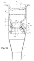
- Fig. 1 is a perspective view showing a condition wherein a fueling-error prevention device according to the present invention is built into a filler neck.
- a fueling-error prevention device is provided in an inside of a fuel flow path L between a fueling opening H and a fuel tank; blocks the fueling by a fueling nozzle N" having a diameter less than a predetermined diameter when the fueling nozzle N" having the diameter less than the predetermined diameter is inserted in the fuel flow path L; and allows the fueling by a fueling nozzle N' having the predetermined diameter when the fueling nozzle N' having the predetermined diameter is inserted in the fuel flow path L.
- such prevention device opens the later-mentioned flap valve 1, and allows an insertion of the fueling nozzle further than the flap valve 1 to allow a fueling thereof.
- the fueling nozzle of the fueling gun which fuels a gasoline fuel and has a diameter smaller than that of the fueling nozzle of the fueling gun which fuels the diesel fuel from the fueling opening H
- such prevention device maintains a valve-closed state of the later-mentioned flap valve 1, and blocks the insertion of the fueling nozzle further than the flap valve 1 to be incapable of the fueling thereof.
- Such prevention device comprises the flap valve 1, first and second sliders 2 and 3, an urging device 4, and a lock member 5.
- the aforementioned members are combined in an approximately cylindrical base 6 whose inner side is one portion of the fuel flow path L. Then, in the present embodiment, by fitting such base 6 in an inside of a filler neck Pa of a filler pipe P structuring the fuel flow path L, the prevention device is provided in the inside of the fuel flow path L.
- Such base 6 has an external diameter which can be housed in the inside of the filler neck Pa with a small gap, and also includes a flange 6a on an upper end of a cylinder. Then, such base 6 is entered in the inside of the filler neck Pa from a lower end side thereof up to a position wherein the flange 6a is caught on an upper end of the filler neck Pa, so that engagement claws represented by the reference numeral 6b in the drawings are engaged with latch-engaged portions which are not shown in the drawings on a filler neck Pa side. Accordingly, the base 6 is assembled in such filler neck Pa.
- the reference numeral 6c in the drawings represents a cap covering an upper surface of the flange 6a.
- window hole-like portions 6e which are removed from a position just below the flange 6a up to a position of an approximately middle in a cylinder axis direction of the base 6.
- the window hole-like portions 6e are respectively provided on both sides in a diametrical direction of the base 6.
- the flap valve 1 is rotatably combined in the first slider 2, and in a valve-closed position, the flap valve 1 closes the fuel flow path L by arranging a flap surface 1a in a direction orthogonal to the cylinder axis direction of the base 6.
- the second slider 3 engages with the flap valve 1 which is in the valve-closed position so as to maintain the valve-closed state.
- the flap valve 1 is positioned in the valve-closed position closing the fuel flow path L by urging so as to block the fueling nozzle from proceeding.
- such flap valve 1 is structured to form an approximately discoid shape having a size closing the fuel flow path L inside the base 6 in the valve-closed position.
- the first slider 2 supports the flap valve 1 openably and closably, and also is supported in the base 6 slidably and movably in a direction crossing an axis line x (a center line in a flow direction of a fuel) of the fuel flow path L.
- such first slider 2 comprises the main body portion 20, and a support portion 21 of the flap valve 1 integrally provided in a lower portion of the main body portion 20.
- the main body portion 20 comprises a ceiling surface portion 20a, right-and-left side surface portions 20b and 20b, and the front surface portion 20d facing the fuel flow path L.
- projections 20c which can be housed in a groove 6h ( Fig. 11 ) provided in support walls 6g formed in such a way as to respectively protrude to an outside in both right-and-left side positions clamping the window hole-like portions 6e in the base 6.
- the first slider 2 slides and moves within a range of the groove 6h.
- the front surface portion 20d forms an arc shape following an arc of an inner surface of the base 6, and also as heading for a lower side, the front surface portion 20d has a slope gradually hanging over an inner side of the fuel flow path L.
- the support portion 21 is structured by a right-and-left pair of side plates 21a and 21a protruding to the lower side from the lower portion of the main body portion 20.
- a right-and-left pair of bearing ear portions 1b and 1b there is formed a right-and-left pair of bearing ear portions 1b and 1b, and in a state wherein the bearing ear portions 1b are housed between a pair of the side plates 21a and 21a of the support portion 21, the bearing ear portions 1b corresponding to a pair of such respective side plates 21a and 21a are rotatably assembled in axis holes 1c and 21b formed in the bearing ear portions 1b and the side plates 21a by passing axis pins 1d.
- a winding portion 1f of a torsion coil spring 1e is held between a pair of the bearing ear portions 1b and 1b of the flap valve 1. Due to the urging of the spring 1e which is held in the aforementioned manner and also whose one end of the spring is caught on a flap valve 1 side and whose the other end of the spring is caught on a back portion 20e side of the first slider 2, the flap valve 1 is positioned in the valve-closed position wherein the flap surface 1a on a base end side thereof is hit against the lower portion of the main body portion 20 of the first slider 2.
- the second slider 3 comprises an engaging portion 30 relative to the flap valve 1 which is in the valve-closed position, and also is supported in the base 6 slidably and movably in the direction crossing the axis line x of the fuel flow path L.
- such second slider 3 comprises the main body portion 31, and the linkage arms 32 whose arm base portions are integrally linked to a lower portion of the main body portion 31, and which protrude in a direction orthogonal to the axis line x of the fuel flow path L.
- the linkage arms 32 are respectively provided on both right and left sides clamping the main body portion 31.
- the linkage arms 32 link the arm base portions to a back side of the main body portion 31 to be positioned outside the base 6.
- the linkage arms 32 protrude to the first slider 2 side in such a way as to clamp the base 6 between a right-and-left pair of the linkage arms 32 and 32, and arm ends are positioned just below the first slider 2.
- the main body portion 31 comprises a ceiling surface portion 31a, right-and-left side surface portions 31b and 31b, and the front surface portion 31c facing the fuel flow path L.
- the front surface portion 31c forms an arc shape following the arc of the inner surface of the base 6, and also as heading for a lower side, the front surface portion 31c has a slope gradually hanging over the inner side of the fuel flow path L.
- a clamping piece 31d protruding to the inner side of the fuel flow path L by leaving an interval for clamping a free end of the flap valve 1 between the main body portion 31.
- the urging device 4 urges the first slider 2 and the second slider 3 in an approaching direction.
- one end of the spring is fastened to one of the linkage arms 32 of the second slider 3, and the other end of the spring is fastened to the other of the linkage arms 32 of the second slider 3.
- the urging device 4 is structured by a coil spring 40 stretched and whose intermediate portion of the spring is pressed against a back portion of the main body portion of the first slider 2.
- the first slider 2 and the second slider 3 are positioned in a position wherein a distance between a lower end side of the front surface portion 20d of the main body portion 20 of the first slider 2 and a lower end side of the front surface portion 31c of the main body portion 31 of the second slider 3 is made slightly smaller than an external diameter of the fueling nozzle N' having the predetermined diameter forming a cylinder shape. ( Fig. 3 )
- the lock member 5 blocks a movement in a separating direction of one of either the first slider 2 or the second slider 3 against the urging of the urging device 4. In the illustrated example, such lock member 5 blocks the movement in a direction wherein the first slider 2 is separated from the second slider 3.
- lock member 5 is supported slidably and movably between a lock position blocking the movement in the separating direction of the first slider 2, and a non-lock position, and also is recoiled and urged toward the lock position.
- such lock member 5 comprises a central portion 50 positioned on the lower side of the first slider 2, and arm portions 51 provided respectively on both right and left sides clamping the central portion 50 in such a way as to protrude toward a side of the second slider 3 from the central portion 50.
- the central portion 50 of the lock member 5 is housed in a space formed on the lower side of the main body portion 20 of the first slider 2 to be movable in a direction along the axis line x of the fuel flow path L, i.e., up and down.
- An upper end of a spring of a compression coil spring 52 whose lower end of the spring contacts with a support portion 6i of the base 6, which is located in a position just below the central portion 50 of the lock member 5 and faces the aforementioned space, is pressed against a lower portion of the central portion 50 of the lock member 5. Due to the spring 52, the lock member 5 is positioned in the lock position.
- abutting portions 50a which become one portion of a front surface portion of the central portion 50 of the lock member 5 which is in the lock position (the position in Fig. 3 ) abut against abutted portions 20f which become one portion of a back portion 20e of the first slider 2 in the support portion 21 of the flap valve 1 of the first slider 2. ( Fig. 13 ) Then, when the lock member 5 moves to the lower side up to the non-lock position (the position in Fig.
- arm end sides of the linkage arms 32 of the second slider 3 and the arm portions 51 of the lock member 5 comprise a cam device moving the lock member 5 to the non-lock position by the movement of the second slider 3 in the separating direction.
- cam device is structured by cam grooves 32a formed on the arm end sides of the linkage arms 32 of the second slider 3, and sliding members 51a formed in the arm portions 51 of the lock member 5.
- one of the right-and-left arm portions 51 and 51 of the lock member 5 is positioned on an inside of one of the right-and-left linkage arms 32 and 32 of the second slider 3, and the sliding member 51a forming a projection formed in an outside of one of the arm portions 51 is housed in the cam groove 32a formed in one of the linkage arms 32.
- the other of the right-and-left arm portions 51 and 51 of the lock member 5 is positioned on the inside of the other of the right-and-left linkage arms 32 and 32 of the second slider 3, and the sliding member 51a forming the projection formed in the outside of the other of the arm portions 51 is housed in the cam groove 32a formed in the other of the linkage arms 32.
- the cam groove 32a positions one groove end 32b, which is close to a main body portion 31 side of the second slider 3, on an upper side; extends from there toward the arm end of the linkage arm 32 in such a way as to form an arc shape; and positions the other groove end 32c on a lower side. Then, in a state before the second slider 3 moves in the separating direction, the sliding member 51a is positioned in one groove end 32b of the cam groove 32a. ( Fig. 2 )
- the blocking of the movement of the first slider 2 in the separating direction by the lock member 5 is released by the movement of the second slider 3 moving against the urging of the urging device 4 by abutting against the fueling nozzle N' having the predetermined diameter accompanied by an insertion of the fueling nozzle N' having the predetermined diameter.
- the aforementioned release allows the movement by the abutment of the fueling nozzle N' of the first slider 2 against the urging of the urging device 4, and the movement of the first slider 2 allows an engagement relative to the flap valve 1 of the second slider 3 to be released.
- the fueling nozzle N' having the predetermined diameter when the fueling nozzle N' having the predetermined diameter is inserted into the fuel flow path L from the fueling opening H, the fueling nozzle N' abuts against both the front surface portion 20d of the main body portion 20 of the first slider 2 and the front surface portion 31c of the main body portion 31 of the second slider 3.
- the first slider 2 does not move in the separating direction immediately, and first, the second slider 3 moves in the separating direction for a predetermined distance. Even if the second slider 3 moves in that manner, the aforementioned clamping piece 31d of the second slider 3 continues to be caught on the free end of the flap valve 1 from the lower side, so that an engagement between the second slider 3 and the flap valve 1 cannot be released simply by the movement of the second slider 3.
- the movement to the valve-opened position of the flap valve 1 closing the fuel flow path L openably is allowed for the first time by the movement of one of the first or the second sliders 2 and 3 which becomes movable as a trigger of the movement of the other of the first or the second sliders 2 and 3. Accordingly, in addition to the movement of the other of the first or the second sliders 2 and 3, as long as a fueling nozzle having a thickness allowing one of the first or the second sliders 2 and 3 to move for the predetermined distance, i.e., the fueling nozzle N' having the predetermined diameter is not inserted into the fuel flow path L, the flap valve 1 never moves to the valve-opened position.
- a lock member which is substantially the same as the aforementioned lock member 5 and is not shown in the drawings, can block the movement of the second slider 3 in the separating direction, and the movement of the lock member, which is not shown in the drawings, to the non-lock position can be also released by interlocking with the movement of the first slider 2 moving against the urging of the urging device 4 by abutting against the fueling nozzle N' having the predetermined diameter accompanied by the insertion of the fueling nozzle N' having the predetermined diameter.
- such release allows the movement by the abutment of the fueling nozzle N' of the second slider 3 against the urging of the urging device 4, and the movement of the second slider 3 releases the engagement relative to the flap valve 1.
- Figs. 15 to 17 comprise the substantially same structure as the fueling-error prevention device shown in Figs. 1 to 14 .
- Figs. 15 to 17 show another example of the fueling-error prevention device structured by modifying a shape of each structural member of the fueling-error prevention device shown in Figs. 1 to 14 . Therefore, the same symbols used in Figs. 1 to 14 are assigned to the substantially same parts shown in Figs. 15 to 17 , and explanations regarding the substantially same structures are omitted.
- the flap valve 1, the torsion coil spring 1e urging the flap valve, and the filler pipe P are structured by metal having a conductive property.
- another example shown in Figs. 15 to 17 comprises an extension portion 1g whose the other spring end, caught on the back portion 20e of the first slider 2 in the torsion coil spring 1e from the lower side, extends outwardly from the back portion 20e further, and is always electrically connected to an inner surface of the fuller pipe P.
- One spring end of the torsion coil spring 1e is pressed against the flap valve 1 from the lower side, and is electrically connected to the flap surface 1a of the flap valve 1.
- the base 6 is structured by connecting a lower end of an upper-portion cylinder body 6" relative to an upper end of a lower-portion cylinder body 6' wherein the flap valve 1, the first slider 2, the second slider 3, the urging device 4, and the lock member 5 are combined, and the flange 6a is formed in the upper-portion cylinder body 6".
- Inside the upper-portion cylinder body 6 there is molded a female screw portion 6j wherein a male screw portion of a filler cap which is not shown in the drawings is screwed, and by fitting the fueling-error prevention device in an inside of the filler neck Pa, a screwing structure of the filler cap can be formed on a filler pip P side.
Abstract
Description
- The present invention relates to an improvement of a fueling-error prevention device which is provided in an inside of a fuel flow path between a fueling opening and a fuel tank; blocks the fueling by a fueling nozzle when the fueling nozzle having a diameter less than a predetermined diameter is inserted in the fuel flow path; and allows the fueling by the fueling nozzle when the fueling nozzle having the predetermined diameter is inserted in the fuel flow path.
- There is a device shown in
Patent Document 1, which prevents the fueling of non-predetermined types of fuels by the fueling nozzle which does not reach the predetermined diameter, i.e., a fueling error, with a mechanical structure. In such device, a flap which becomes a valve body is rotatably attached to one of a pair of reception means which can be pressed apart outwardly, and in a state before a pair of the reception means is pressed apart, a free end of the flap is engaged with the other of a pair of the reception means so as to block a rotation of the flap in a valve-opened position. Then, in such device, when a fueling nozzle, having a thickness allowing a pair of the reception means to be separated for a size releasing the aforementioned engagement, i.e., a thickness allowing a pair of the reception means to be pressed apart, is inserted, the rotation of the flap in the valve-opened position is allowed. Hence, even when only one of a pair of the reception means is moved outward by the inserted fueling nozzle, such device has a structure allowing the aforementioned engagement to be released. - Patent Document 1: Japanese Unexamined Patent Publication No.
2009-502611 - The main feature to be solved by the present invention is to provide a device which can reliably prevent the fueling error with the mechanical structure.
- In order to achieve the aforementioned problem, in the present invention, from the first aspect, a fueling-error prevention device is provided inside of a fuel flow path between a fueling opening and a fuel tank. The fueling-error prevention device comprises a flap valve provided on one of the first or the second sliders which are disposed opposite each other with the fuel flow path positioned therebetween. Accompanied by an insertion of a fueling nozzle having a predetermined diameter, the fueling nozzle abuts against one of both sliders, so that one slider moves in a separating direction so as to allow the other of both sliders to move in the separating direction. Accordingly, due to the movement of the other slider in the separating direction by the abutment of the fueling nozzle, the flap valve is allowed to be opened.
- Also, in order to achieve the aforementioned problem, in the present invention, from a second aspect, the fueling-error prevention device is provided inside of the fuel flow path between the fueling opening and the fuel tank. The fueling-error prevention device comprises the flap valve positioned in a valve-closed position blocking the fuel flow path by urging to block the fueling nozzle from proceeding; the first slider supporting the flap valve openably and closably, and also supported slidably and movably in a direction crossing an axis line of the fuel flow path; the second slider comprising an engaging portion relative to the flap valve which is in the valve-closed position, and also supported slidably and movably in the direction crossing the axis line of the fuel flow path; an urging device urging the first slider and the second slider in an approaching direction; and a lock member blocking one of either the first slider or the second slider from moving in the separating direction against the urging of the urging device. The blocking of the movement by the lock member is released by the movement of the other of the first slider or the second slider which moves against the urging of the urging device by the abutment of the fueling nozzle having the predetermined diameter accompanied by the insertion of the fueling nozzle having the predetermined diameter. The aforementioned release allows one of the first slider or the second slider to move against the urging of the urging device due to the abutment of the fueling nozzle. Due to the movement of one slider, an engagement of the second slider relative to the flap valve is released.
- In that case, furthermore, one of preferable aspects is that the lock member is supported slidably and movably between a lock position blocking one of either the first slider or the second slider from moving in the separating direction, and a non-lock position, and also that the lock member is recoiled and urged toward the lock position. Also, in that case, furthermore, it is preferable that such lock member includes an abutting portion relative to a back portion of one of either the first slider or the second slider, and moves up to the non-lock position in a direction along the axis line of the fuel flow path against the urging to release the abutment of the abutting portion relative to the back portion.
- A movement to a valve-opened position of the flap valve closing the fuel flow path openably is allowed for the first time by the movement of one of the first or the second sliders which becomes movable as a trigger of the movement of the other of the first or the second sliders. Accordingly, in addition to the movement of the other of the first or the second sliders, as long as a fueling nozzle having a thickness allowing one of the first or the second sliders to move for a predetermined distance, i.e., the fueling nozzle having the predetermined diameter is not inserted into the fuel flow path, the flap valve never moves to the valve-opened position. For example, even if the fueling nozzle which does not reach the predetermined diameter is inserted into the fuel flow path, and is operated to sway inside the fuel flow path, only the other of the first or the second sliders moves, and the flap valve is never opened.
- According to the present invention, the fueling of the non-predetermined types of fuels by the fueling nozzle which does not reach the predetermined diameter, i.e., the fueling error, can be reliably prevented.
-
Fig. 1 is a perspective view showing a condition wherein a fueling-error prevention device according to the present invention is built into a filler neck. -
Fig. 2 is a side view of the prevention device in a state wherein a fueling nozzle is not inserted. -
Fig. 3 is a vertical cross-sectional view of the state ofFig. 2 . -
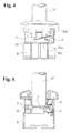
Fig. 4 is a side view of the prevention device in a state wherein the fueling nozzle having a predetermined diameter is inserted, and shows a state just before a flap valve is open. -
Fig. 5 is a vertical cross-sectional view of the state ofFig. 4 . -
Fig. 6 is a cross-sectional view of the prevention device in the state wherein the fueling nozzle having the predetermined diameter is inserted, and shows a state wherein the flap valve is open. -
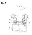
Fig. 7 is a cross-sectional view of the prevention device in a state wherein the fueling nozzle having a diameter less than the predetermined diameter is inserted. -
Fig. 8 is an exploded perspective view of the prevention device. -
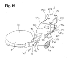
Fig. 9 is a perspective view of a second slider and a lock member. -
Fig. 10 is a perspective view of a first slider and the flap valve. -
Fig. 11 is a perspective view showing the prevention device by cutting away a flange of a base. -
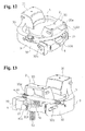
Fig. 12 is a perspective view showing a state wherein the first slider, the second slider, the flap valve, the lock member, and an urging device are combined by omitting the base, and the lock member is in a lock position. -
Fig. 13 is a perspective view showing the state ofFig. 12 viewed from a side of the lock member. -
Fig. 14 is a perspective view showing a state wherein the lock member is moved to a non-lock position from the state ofFig. 13 . -
Fig. 15 is a side view showing a modified example of a shape of the prevention device shown inFigs. 1 to 14 . -
Fig. 16 is a cross-sectional view showing a condition wherein the prevention device shown inFig. 15 is built into the filler neck. -
Fig. 17 is a perspective view showing the first slider and the flap valve structuring the prevention device shown inFig. 15 . - Hereinafter, with reference to
Figs. 1 to 17 , a typical embodiment of the present invention will be explained. A fueling-error prevention device according to the present embodiment is provided in an inside of a fuel flow path L between a fueling opening H and a fuel tank; blocks the fueling by a fueling nozzle N" having a diameter less than a predetermined diameter when the fueling nozzle N" having the diameter less than the predetermined diameter is inserted in the fuel flow path L; and allows the fueling by a fueling nozzle N' having the predetermined diameter when the fueling nozzle N' having the predetermined diameter is inserted in the fuel flow path L. - Typically, when the fueling nozzle of a fueling gun, which fuels a diesel fuel from the fueling opening H, is inserted, such prevention device opens the later-mentioned
flap valve 1, and allows an insertion of the fueling nozzle further than theflap valve 1 to allow a fueling thereof. On the other hand, when there is inserted the fueling nozzle of the fueling gun which fuels a gasoline fuel and has a diameter smaller than that of the fueling nozzle of the fueling gun which fuels the diesel fuel from the fueling opening H, such prevention device maintains a valve-closed state of the later-mentionedflap valve 1, and blocks the insertion of the fueling nozzle further than theflap valve 1 to be incapable of the fueling thereof. - Such prevention device comprises the
flap valve 1, first andsecond sliders urging device 4, and alock member 5. In the present embodiment, the aforementioned members are combined in an approximatelycylindrical base 6 whose inner side is one portion of the fuel flow path L. Then, in the present embodiment, by fittingsuch base 6 in an inside of a filler neck Pa of a filler pipe P structuring the fuel flow path L, the prevention device is provided in the inside of the fuel flow path L. -
Such base 6 has an external diameter which can be housed in the inside of the filler neck Pa with a small gap, and also includes aflange 6a on an upper end of a cylinder. Then,such base 6 is entered in the inside of the filler neck Pa from a lower end side thereof up to a position wherein theflange 6a is caught on an upper end of the filler neck Pa, so that engagement claws represented by thereference numeral 6b in the drawings are engaged with latch-engaged portions which are not shown in the drawings on a filler neck Pa side. Accordingly, thebase 6 is assembled in such filler neck Pa. Thereference numeral 6c in the drawings represents a cap covering an upper surface of theflange 6a. - In an illustrated example, in one portion of
side walls 6d ofsuch base 6, there are formed window hole-like portions 6e which are removed from a position just below theflange 6a up to a position of an approximately middle in a cylinder axis direction of thebase 6. The window hole-like portions 6e are respectively provided on both sides in a diametrical direction of thebase 6. Then, one portion (afront surface portion 20d side of the later-mentioned main body portion 20) of thefirst slider 2 protrudes to the inside of the fuel flow path L from one of such window hole-like portions 6e, and one portion (afront surface portion 31c side of the later-mentioned main body portion 31) of thesecond slider 3 protrudes to the inside of the fuel flow path L from the other of such window hole-like portions 6e. Theflap valve 1 is rotatably combined in thefirst slider 2, and in a valve-closed position, theflap valve 1 closes the fuel flow path L by arranging a flap surface 1a in a direction orthogonal to the cylinder axis direction of thebase 6. (Fig. 3 /the valve-closed position) In a state wherein the fueling nozzle N' having the predetermined diameter is not inserted, thesecond slider 3 engages with theflap valve 1 which is in the valve-closed position so as to maintain the valve-closed state. On an outer circumferential portion of thebase 6, there is formed aguide portion 6f of the later-mentionedlinkage arms 32 of thesecond slider 3. Also, on a lower side of thefirst slider 2, there is supported thelock member 5 movably up and down inside the window hole-like portions 6e. - The
flap valve 1 is positioned in the valve-closed position closing the fuel flow path L by urging so as to block the fueling nozzle from proceeding. In the illustrated example,such flap valve 1 is structured to form an approximately discoid shape having a size closing the fuel flow path L inside thebase 6 in the valve-closed position. - The
first slider 2 supports theflap valve 1 openably and closably, and also is supported in thebase 6 slidably and movably in a direction crossing an axis line x (a center line in a flow direction of a fuel) of the fuel flow path L. - In the illustrated example, such
first slider 2 comprises themain body portion 20, and asupport portion 21 of theflap valve 1 integrally provided in a lower portion of themain body portion 20. Themain body portion 20 comprises aceiling surface portion 20a, right-and-leftside surface portions front surface portion 20d facing the fuel flow path L. In the right-and-leftside surface portions projections 20c which can be housed in agroove 6h (Fig. 11 ) provided in support walls 6g formed in such a way as to respectively protrude to an outside in both right-and-left side positions clamping the window hole-like portions 6e in thebase 6. Thefirst slider 2 slides and moves within a range of thegroove 6h. Thefront surface portion 20d forms an arc shape following an arc of an inner surface of thebase 6, and also as heading for a lower side, thefront surface portion 20d has a slope gradually hanging over an inner side of the fuel flow path L. - The
support portion 21 is structured by a right-and-left pair ofside plates main body portion 20. In the illustrated example, on a base end of theflap valve 1, there is formed a right-and-left pair of bearing ear portions 1b and 1b, and in a state wherein the bearing ear portions 1b are housed between a pair of theside plates support portion 21, the bearing ear portions 1b corresponding to a pair of suchrespective side plates side plates 21a by passing axis pins 1d. - In the illustrated example, a winding portion 1f of a
torsion coil spring 1e is held between a pair of the bearing ear portions 1b and 1b of theflap valve 1. Due to the urging of thespring 1e which is held in the aforementioned manner and also whose one end of the spring is caught on aflap valve 1 side and whose the other end of the spring is caught on aback portion 20e side of thefirst slider 2, theflap valve 1 is positioned in the valve-closed position wherein the flap surface 1a on a base end side thereof is hit against the lower portion of themain body portion 20 of thefirst slider 2. - The
second slider 3 comprises an engagingportion 30 relative to theflap valve 1 which is in the valve-closed position, and also is supported in thebase 6 slidably and movably in the direction crossing the axis line x of the fuel flow path L. - In the illustrated example, such
second slider 3 comprises themain body portion 31, and thelinkage arms 32 whose arm base portions are integrally linked to a lower portion of themain body portion 31, and which protrude in a direction orthogonal to the axis line x of the fuel flow path L. Thelinkage arms 32 are respectively provided on both right and left sides clamping themain body portion 31. Thelinkage arms 32 link the arm base portions to a back side of themain body portion 31 to be positioned outside thebase 6. Thelinkage arms 32 protrude to thefirst slider 2 side in such a way as to clamp thebase 6 between a right-and-left pair of thelinkage arms first slider 2. On the outer circumferential portion of thebase 6, there is formed theguide portion 6f forming a step-difference form and facing a lower surface of theflange 6a, and thelinkage arms 32 of thesecond slider 3 slide on theguide portion 6f. - The
main body portion 31 comprises aceiling surface portion 31a, right-and-left side surface portions 31b and 31b, and thefront surface portion 31c facing the fuel flow path L. Thefront surface portion 31c forms an arc shape following the arc of the inner surface of thebase 6, and also as heading for a lower side, thefront surface portion 31c has a slope gradually hanging over the inner side of the fuel flow path L. Also, on the lower side of thefront surface portion 31c, there is provided aclamping piece 31d protruding to the inner side of the fuel flow path L by leaving an interval for clamping a free end of theflap valve 1 between themain body portion 31. - The urging
device 4 urges thefirst slider 2 and thesecond slider 3 in an approaching direction. In the illustrated example, insuch urging device 4, one end of the spring is fastened to one of thelinkage arms 32 of thesecond slider 3, and the other end of the spring is fastened to the other of thelinkage arms 32 of thesecond slider 3. Also, the urgingdevice 4 is structured by a coil spring 40 stretched and whose intermediate portion of the spring is pressed against a back portion of the main body portion of thefirst slider 2. - Due to such spring 40, the
first slider 2 and thesecond slider 3 are positioned in a position wherein a distance between a lower end side of thefront surface portion 20d of themain body portion 20 of thefirst slider 2 and a lower end side of thefront surface portion 31c of themain body portion 31 of thesecond slider 3 is made slightly smaller than an external diameter of the fueling nozzle N' having the predetermined diameter forming a cylinder shape. (Fig. 3 ) - The
lock member 5 blocks a movement in a separating direction of one of either thefirst slider 2 or thesecond slider 3 against the urging of the urgingdevice 4. In the illustrated example,such lock member 5 blocks the movement in a direction wherein thefirst slider 2 is separated from thesecond slider 3. - Also,
such lock member 5 is supported slidably and movably between a lock position blocking the movement in the separating direction of thefirst slider 2, and a non-lock position, and also is recoiled and urged toward the lock position. - In the illustrated example,
such lock member 5 comprises acentral portion 50 positioned on the lower side of thefirst slider 2, andarm portions 51 provided respectively on both right and left sides clamping thecentral portion 50 in such a way as to protrude toward a side of thesecond slider 3 from thecentral portion 50. - The
central portion 50 of thelock member 5 is housed in a space formed on the lower side of themain body portion 20 of thefirst slider 2 to be movable in a direction along the axis line x of the fuel flow path L, i.e., up and down. An upper end of a spring of acompression coil spring 52 whose lower end of the spring contacts with asupport portion 6i of thebase 6, which is located in a position just below thecentral portion 50 of thelock member 5 and faces the aforementioned space, is pressed against a lower portion of thecentral portion 50 of thelock member 5. Due to thespring 52, thelock member 5 is positioned in the lock position. - Specifically, in the illustrated example, abutting
portions 50a which become one portion of a front surface portion of thecentral portion 50 of thelock member 5 which is in the lock position (the position inFig. 3 ) abut against abuttedportions 20f which become one portion of aback portion 20e of thefirst slider 2 in thesupport portion 21 of theflap valve 1 of thefirst slider 2. (Fig. 13 ) Then, when thelock member 5 moves to the lower side up to the non-lock position (the position inFig. 5 ) due to the movement of thesecond slider 3 in the separating direction as mentioned later, thecentral portion 50 of thelock member 5 is entered into the lower side of thesupport portion 21 of theflap valve 1 of thefirst slider 2 so as to release the abutment between the abuttingportions 50a and theabutted portions 20f. (Fig. 14 ) - Also, arm end sides of the
linkage arms 32 of thesecond slider 3 and thearm portions 51 of thelock member 5 comprise a cam device moving thelock member 5 to the non-lock position by the movement of thesecond slider 3 in the separating direction. In the illustrated example, such cam device is structured bycam grooves 32a formed on the arm end sides of thelinkage arms 32 of thesecond slider 3, and slidingmembers 51a formed in thearm portions 51 of thelock member 5. In the illustrated example, one of the right-and-left arm portions lock member 5 is positioned on an inside of one of the right-and-leftlinkage arms second slider 3, and the slidingmember 51a forming a projection formed in an outside of one of thearm portions 51 is housed in thecam groove 32a formed in one of thelinkage arms 32. Also, the other of the right-and-left arm portions lock member 5 is positioned on the inside of the other of the right-and-leftlinkage arms second slider 3, and the slidingmember 51a forming the projection formed in the outside of the other of thearm portions 51 is housed in thecam groove 32a formed in the other of thelinkage arms 32. Thecam groove 32a positions onegroove end 32b, which is close to amain body portion 31 side of thesecond slider 3, on an upper side; extends from there toward the arm end of thelinkage arm 32 in such a way as to form an arc shape; and positions theother groove end 32c on a lower side. Then, in a state before thesecond slider 3 moves in the separating direction, the slidingmember 51a is positioned in onegroove end 32b of thecam groove 32a. (Fig. 2 ) - Then, in the prevention device according to the present embodiment, the blocking of the movement of the
first slider 2 in the separating direction by thelock member 5 is released by the movement of thesecond slider 3 moving against the urging of the urgingdevice 4 by abutting against the fueling nozzle N' having the predetermined diameter accompanied by an insertion of the fueling nozzle N' having the predetermined diameter. The aforementioned release allows the movement by the abutment of the fueling nozzle N' of thefirst slider 2 against the urging of the urgingdevice 4, and the movement of thefirst slider 2 allows an engagement relative to theflap valve 1 of thesecond slider 3 to be released. - Specifically, when the fueling nozzle N' having the predetermined diameter is inserted into the fuel flow path L from the fueling opening H, the fueling nozzle N' abuts against both the
front surface portion 20d of themain body portion 20 of thefirst slider 2 and thefront surface portion 31c of themain body portion 31 of thesecond slider 3. However, due to thelock member 5, thefirst slider 2 does not move in the separating direction immediately, and first, thesecond slider 3 moves in the separating direction for a predetermined distance. Even if thesecond slider 3 moves in that manner, theaforementioned clamping piece 31d of thesecond slider 3 continues to be caught on the free end of theflap valve 1 from the lower side, so that an engagement between thesecond slider 3 and theflap valve 1 cannot be released simply by the movement of thesecond slider 3. On the other hand, when thesecond slider 3 moves in the separating direction in that manner, the aforementioned slidingmembers 51a are guided to theother groove end 32c side positioned lower than onegroove end 32b from onegroove end 32b of thecam grooves 32a, so that (Fig. 4 ) thelock member 5 moves to the lower side up to the non-lock position against the urging of thespring 52. (Fig. 5 ) When thelock member 5 moves up to the non-lock position, the abutment of the abuttingportions 50a of thelock member 5 relative to the abuttedportions 20f structuring one portion of theback portion 20e of thefirst slider 2 is released, so that thefirst slider 2 also becomes movable in the separating direction by the fueling nozzle N' so as to carry out such movement of thefirst slider 2. (Fig. 5 ) Thereby, theflap valve 1 is pushed by the fueling nozzle N' inserted by releasing a capture of theclamping piece 31d relative to the free end of theflap valve 1, so that theflap valve 1 rotates up to a valve-opened position wherein the free end faces the lower side so as to allow the fueling nozzle N' to proceed further than an installation position of theflap valve 1 and to allow the fueling. (Fig. 6 ) - After the completion of the fueling, when the fueling nozzle N' is operated to be pulled out of the fuel flow path L, first, due to the urging of the
torsion coil spring 1e, theflap valve 1 rotates and returns to the valve-closed position. Next, due to the urging of the urgingdevice 4, thefirst slider 2 and thesecond slider 3 are pushed back to a position before the movement in the separating direction, and accompanied by that, thelock member 5 returns to the lock position so as to abut the abuttingportions 50a against the abuttedportions 20f of thefirst slider 2 again. - In the prevention device according to the present embodiment, the movement to the valve-opened position of the
flap valve 1 closing the fuel flow path L openably is allowed for the first time by the movement of one of the first or thesecond sliders second sliders second sliders second sliders flap valve 1 never moves to the valve-opened position. For example, even if the fueling nozzle N" which does not reach the predetermined diameter is inserted into the fuel flow path L, and is operated to sway inside the fuel flow path L, only thesecond slider 3 moves, and the aforementioned engagement with theflap valve 1 by thesecond slider 3 is never released. (Fig. 7 ) Thereby, in the prevention device according to the present embodiment, the fueling of non-predetermined types of fuels by the fueling nozzle N" which does not reach the predetermined diameter, i.e., a fueling error, can be reliably prevented. - Incidentally, contrary to the illustrated example, a lock member, which is substantially the same as the
aforementioned lock member 5 and is not shown in the drawings, can block the movement of thesecond slider 3 in the separating direction, and the movement of the lock member, which is not shown in the drawings, to the non-lock position can be also released by interlocking with the movement of thefirst slider 2 moving against the urging of the urgingdevice 4 by abutting against the fueling nozzle N' having the predetermined diameter accompanied by the insertion of the fueling nozzle N' having the predetermined diameter. In the aforementioned case, such release allows the movement by the abutment of the fueling nozzle N' of thesecond slider 3 against the urging of the urgingdevice 4, and the movement of thesecond slider 3 releases the engagement relative to theflap valve 1. -
Figs. 15 to 17 comprise the substantially same structure as the fueling-error prevention device shown inFigs. 1 to 14 . However,Figs. 15 to 17 show another example of the fueling-error prevention device structured by modifying a shape of each structural member of the fueling-error prevention device shown inFigs. 1 to 14 . Therefore, the same symbols used inFigs. 1 to 14 are assigned to the substantially same parts shown inFigs. 15 to 17 , and explanations regarding the substantially same structures are omitted. - In another example shown in
Figs. 15 to 17 , theflap valve 1, thetorsion coil spring 1e urging the flap valve, and the filler pipe P are structured by metal having a conductive property. At the same time, another example shown inFigs. 15 to 17 comprises an extension portion 1g whose the other spring end, caught on theback portion 20e of thefirst slider 2 in thetorsion coil spring 1e from the lower side, extends outwardly from theback portion 20e further, and is always electrically connected to an inner surface of the fuller pipe P. One spring end of thetorsion coil spring 1e is pressed against theflap valve 1 from the lower side, and is electrically connected to the flap surface 1a of theflap valve 1. Thereby, in another example shown inFigs. 15 to 17 , when the fueling nozzle is inserted from the fueling opening H, and an end of the fueling nozzle touches theflap valve 1, the fueling nozzle and the filler pipe P are electrically connected through the fueling-error prevention device so as to have earth-connection. - Also, in another example shown in
Figs. 15 to 17 , thebase 6 is structured by connecting a lower end of an upper-portion cylinder body 6" relative to an upper end of a lower-portion cylinder body 6' wherein theflap valve 1, thefirst slider 2, thesecond slider 3, the urgingdevice 4, and thelock member 5 are combined, and theflange 6a is formed in the upper-portion cylinder body 6". Inside the upper-portion cylinder body 6", there is molded afemale screw portion 6j wherein a male screw portion of a filler cap which is not shown in the drawings is screwed, and by fitting the fueling-error prevention device in an inside of the filler neck Pa, a screwing structure of the filler cap can be formed on a filler pip P side.
All contents of the specification, claims, drawings, and abstract of Japanese Patent Application No.2009-263189 filed on November 18, 2009
Claims (4)
- A fueling-error prevention device adapted to be provided inside a fuel flow path between a fueling opening and a fuel tank, comprising:a flap valve provided on one of first and second sliders disposed opposite each other relative to the fuel flow path,wherein by moving one of the two sliders in a separating direction by an abutment of a fueling nozzle against one slider by inserting the fueling nozzle having a predetermined diameter, the other of the two sliders is movable in the separating direction, and the flap valve is openable by a movement of the other slider in the separating direction by the abutment of the fueling nozzle.
- A fueling-error prevention device adapted to be provided inside a fuel flow path between a fueling opening and a fuel tank, comprising:a flap valve positioned in a valve-closed position for closing the fuel flow path by urging to block a fueling nozzle from proceeding;a first slider supporting the flap valve openably and closably, and also supported slidably and movably in a direction crossing an axis line of the fuel flow path;a second slider having an engaging portion relative to the flap valve which is in the valve-closed position, and also supported slidably and movably in the direction crossing the axis line of the fuel flow path;an urging device urging the first slider and the second slider in an approaching direction; anda lock member blocking one of either the first slider or the second slider from moving in a separating direction against urging of the urging device,wherein blocking of a movement by the lock member is released by a movement of the other of the first slider and the second slider moving against the urging of the urging device by an abutment by inserting the fueling nozzle having a predetermined diameter, and the release allows one of the first slider and the second slider to move against the urging of the urging device by the abutment of the fueling nozzle, and by the movement of the one slider, an engagement of the second slider relative to the flap valve is released.
- A fueling-error prevention device according to claim 2, wherein the lock member is supported slidably and movably between a non-lock position and a lock position blocking the movement of either the first slider or the second slider in the separating direction, and the lock member is resiliently urged toward the lock position.
- A fueling-error prevention device according to claim 3, wherein the lock member includes an abutting portion relative to a back portion of either the first slider or the second slider, and moves up to the non-lock position in a direction along the axis line of the fuel flow path against the urging to release abutment of the abutting portion relative to the back portion.
Applications Claiming Priority (2)
| Application Number | Priority Date | Filing Date | Title |
|---|---|---|---|
| JP2009263189 | 2009-11-18 | ||
| PCT/JP2010/070494 WO2011062193A1 (en) | 2009-11-18 | 2010-11-17 | Device for preventing fueling error |
Publications (3)
| Publication Number | Publication Date |
|---|---|
| EP2502772A1 true EP2502772A1 (en) | 2012-09-26 |
| EP2502772A4 EP2502772A4 (en) | 2013-06-26 |
| EP2502772B1 EP2502772B1 (en) | 2014-08-27 |
Family
ID=44059671
Family Applications (1)
| Application Number | Title | Priority Date | Filing Date |
|---|---|---|---|
| EP10831587.0A Active EP2502772B1 (en) | 2009-11-18 | 2010-11-17 | Device for preventing fueling error |
Country Status (5)
| Country | Link |
|---|---|
| US (1) | US9205736B2 (en) |
| EP (1) | EP2502772B1 (en) |
| JP (1) | JP5286423B2 (en) |
| CN (1) | CN102686438B (en) |
| WO (1) | WO2011062193A1 (en) |
Cited By (1)
| Publication number | Priority date | Publication date | Assignee | Title |
|---|---|---|---|---|
| WO2021070043A1 (en) * | 2019-10-09 | 2021-04-15 | Gerdes Gmbh | Tank filler neck closure for a fuel tank |
Families Citing this family (23)
| Publication number | Priority date | Publication date | Assignee | Title |
|---|---|---|---|---|
| CN102131706B (en) * | 2008-08-20 | 2015-02-11 | 伊利诺斯工具制品有限公司 | Mis-fueling inhibitor |
| US10000117B2 (en) | 2012-02-17 | 2018-06-19 | Stant Usa Corp. | Filler neck closure assembly |
| EP2636555B1 (en) * | 2012-03-08 | 2014-04-30 | Magna Steyr Fuel Systems GmbH | Fill support for a diesel fuel container with a blocking device |
| ITRM20120239A1 (en) * | 2012-05-24 | 2013-11-25 | Glomeria Therapeutics S R L | CONNECTION DEVICE |
| KR101417637B1 (en) * | 2013-05-08 | 2014-07-08 | 현대자동차주식회사 | Filler neck device for preventing fuel from mixing |
| US9701194B2 (en) | 2013-05-10 | 2017-07-11 | Stant Usa Corp. | Fuel-dispensing nozzle inhibitor |
| KR101481272B1 (en) * | 2013-05-28 | 2015-01-09 | 현대자동차주식회사 | Filler neck device for preventing fuel from mixing |
| KR101498490B1 (en) * | 2013-11-29 | 2015-03-05 | 삼보모터스주식회사 | Fuel filler neck device of vehicle fuel-system |
| KR101481343B1 (en) * | 2013-12-10 | 2015-01-09 | 현대자동차주식회사 | Misfuelling prevention system for vehicles |
| KR101510051B1 (en) * | 2014-04-16 | 2015-04-07 | 현대자동차주식회사 | Misfuelling prevention system for vehicles |
| DE102015107681A1 (en) * | 2015-05-15 | 2016-11-17 | Illinois Tool Works Inc. | filler pipe |
| US9873322B2 (en) * | 2015-09-16 | 2018-01-23 | Stant Usa Corp. | Closure assembly for fuel tank filler neck |
| US10081241B2 (en) | 2015-12-10 | 2018-09-25 | Curtis Alan Roys | Diesel fuel guard |
| WO2017145914A1 (en) * | 2016-02-22 | 2017-08-31 | 八千代工業株式会社 | Erroneous oil feed prevention device |
| KR101795235B1 (en) * | 2016-04-08 | 2017-11-07 | 현대자동차주식회사 | Filler neck device for preventing fuel from mixing |
| KR101725005B1 (en) * | 2016-04-29 | 2017-04-07 | 현대자동차주식회사 | Fuel mixing prevention device for vehicle |
| EP3473467B1 (en) | 2016-06-20 | 2021-06-30 | Yachiyo Industry Co., Ltd. | Erroneous refueling prevention device |
| US11142063B2 (en) * | 2019-08-01 | 2021-10-12 | Illinois Tool Works Inc. | Filler neck for filling an operating substance or additive into a vehicle tank by means of a fuel pump nozzle |
| KR102174927B1 (en) * | 2019-10-28 | 2020-11-06 | 삼보모터스주식회사 | Capless misfuelling prevention device |
| US11597269B2 (en) | 2019-11-13 | 2023-03-07 | Toyoda Gosei Co., Ltd. | Fuel device |
| JP7131529B2 (en) * | 2019-11-13 | 2022-09-06 | 豊田合成株式会社 | Lubricator |
| JP7192746B2 (en) * | 2019-11-13 | 2022-12-20 | 豊田合成株式会社 | Lubricator |
| JP7131530B2 (en) * | 2019-11-13 | 2022-09-06 | 豊田合成株式会社 | Lubricator |
Citations (5)
| Publication number | Priority date | Publication date | Assignee | Title |
|---|---|---|---|---|
| AT7933U1 (en) * | 2004-07-16 | 2005-11-15 | Tesma Motoren Getriebetechnik | FILLING TUBE FOR THE FUEL TANK OF A MOTOR VEHICLE WITH SELECTIVE OPENING |
| DE202005012256U1 (en) * | 2005-07-27 | 2006-12-14 | Reutter Metallwarenfabrik Gmbh | Misfuelling device |
| GB2431634A (en) * | 2005-10-25 | 2007-05-02 | Rhys Holdaway | Device to prevent incorrect fuelling of a vehicle |
| DE202007010406U1 (en) * | 2007-07-19 | 2008-11-20 | Reutter Gmbh | Fuel Can |
| DE202008011199U1 (en) * | 2008-08-22 | 2009-10-29 | Magna Steyr Fuel Systems Gmbh | Tank neck with locking device |
Family Cites Families (17)
| Publication number | Priority date | Publication date | Assignee | Title |
|---|---|---|---|---|
| DE10037824B4 (en) * | 2000-08-03 | 2009-06-10 | Daimler Ag | Device for preventing the insertion of a fuel nozzle |
| US7077178B2 (en) * | 2004-08-11 | 2006-07-18 | Stant Manufacturing Inc. | Fuel-dispensing nozzle inhibitor |
| US7302977B2 (en) * | 2004-09-30 | 2007-12-04 | Stant Manufacturing Inc. | Fuel-dispensing nozzle inhibitor |
| US6968874B1 (en) * | 2004-10-07 | 2005-11-29 | Martinrea Industries, Inc. | Capless automotive fueling system |
| US7665493B2 (en) * | 2005-02-10 | 2010-02-23 | Stant Manufacturing Inc. | Fuel-dispensing nozzle inhibitor |
| US7293586B2 (en) * | 2005-06-22 | 2007-11-13 | Stant Manufacturing Inc. | Fuel-dispensing nozzle inhibitor |
| DE102006014438B4 (en) * | 2006-03-27 | 2009-12-24 | Alfmeier Präzision AG Baugruppen und Systemlösungen | Tank filler neck for diesel vehicles |
| US20080041492A1 (en) * | 2006-08-21 | 2008-02-21 | Martinrea Industries, Inc. | Automotive fuel filling system |
| AT9945U1 (en) * | 2007-03-27 | 2008-06-15 | Magna Steyr Fuel Systems Gesmb | FILLING IN A FUEL TANK WITH PROTECTION BEFORE FAILING |
| US7967041B2 (en) * | 2007-07-19 | 2011-06-28 | Stant Usa Corp. | Fuel-dispensing nozzle inhibitor |
| EP2093090B1 (en) * | 2008-02-21 | 2014-07-23 | Stant USA Corp. | Fuel-dispensing nozzle inhibitor |
| US20100218849A1 (en) * | 2009-02-27 | 2010-09-02 | Toyoda Gosei Co., Ltd. | Fuel tank opening-closing device |
| JP5666330B2 (en) * | 2011-02-07 | 2015-02-12 | 株式会社ニフコ | Oil filler opening and closing device |
| JP5767822B2 (en) * | 2011-02-07 | 2015-08-19 | 株式会社ニフコ | Oil filler opening and closing device |
| US20120285579A1 (en) * | 2011-05-12 | 2012-11-15 | Technical Chemical Company | Fuel additive system |
| US20140209203A1 (en) * | 2011-05-12 | 2014-07-31 | Technical Chemical Company | Container construction for dispensing into a fuel receptacle |
| EP2636555B1 (en) * | 2012-03-08 | 2014-04-30 | Magna Steyr Fuel Systems GmbH | Fill support for a diesel fuel container with a blocking device |
-
2010
- 2010-11-17 US US13/510,456 patent/US9205736B2/en active Active
- 2010-11-17 JP JP2011541936A patent/JP5286423B2/en active Active
- 2010-11-17 CN CN201080052023.7A patent/CN102686438B/en active Active
- 2010-11-17 EP EP10831587.0A patent/EP2502772B1/en active Active
- 2010-11-17 WO PCT/JP2010/070494 patent/WO2011062193A1/en active Application Filing
Patent Citations (5)
| Publication number | Priority date | Publication date | Assignee | Title |
|---|---|---|---|---|
| AT7933U1 (en) * | 2004-07-16 | 2005-11-15 | Tesma Motoren Getriebetechnik | FILLING TUBE FOR THE FUEL TANK OF A MOTOR VEHICLE WITH SELECTIVE OPENING |
| DE202005012256U1 (en) * | 2005-07-27 | 2006-12-14 | Reutter Metallwarenfabrik Gmbh | Misfuelling device |
| GB2431634A (en) * | 2005-10-25 | 2007-05-02 | Rhys Holdaway | Device to prevent incorrect fuelling of a vehicle |
| DE202007010406U1 (en) * | 2007-07-19 | 2008-11-20 | Reutter Gmbh | Fuel Can |
| DE202008011199U1 (en) * | 2008-08-22 | 2009-10-29 | Magna Steyr Fuel Systems Gmbh | Tank neck with locking device |
Non-Patent Citations (1)
| Title |
|---|
| See also references of WO2011062193A1 * |
Cited By (1)
| Publication number | Priority date | Publication date | Assignee | Title |
|---|---|---|---|---|
| WO2021070043A1 (en) * | 2019-10-09 | 2021-04-15 | Gerdes Gmbh | Tank filler neck closure for a fuel tank |
Also Published As
| Publication number | Publication date |
|---|---|
| CN102686438B (en) | 2015-04-29 |
| JP5286423B2 (en) | 2013-09-11 |
| EP2502772B1 (en) | 2014-08-27 |
| CN102686438A (en) | 2012-09-19 |
| JPWO2011062193A1 (en) | 2013-04-04 |
| WO2011062193A1 (en) | 2011-05-26 |
| US20120279612A1 (en) | 2012-11-08 |
| US9205736B2 (en) | 2015-12-08 |
| EP2502772A4 (en) | 2013-06-26 |
Similar Documents
| Publication | Publication Date | Title |
|---|---|---|
| EP2502772B1 (en) | Device for preventing fueling error | |
| US10513174B2 (en) | Vehicle lid device | |
| US20110214783A1 (en) | Device for preventing fueling error | |
| US20160010370A1 (en) | Locking device | |
| US11603683B2 (en) | Lid opening and closing device for vehicle | |
| CN102829179B (en) | Motion transmitting remote control assembly having a terminal body with a transverse opening | |
| US10000116B2 (en) | Fuel filling aperture opening and closing device | |
| EP3473467B1 (en) | Erroneous refueling prevention device | |
| KR20110044034A (en) | Latching assembly for door | |
| US11279224B2 (en) | Lid opening and closing device for vehicle | |
| KR101481343B1 (en) | Misfuelling prevention system for vehicles | |
| US10500948B2 (en) | Fuel filling device | |
| US10759271B2 (en) | Fuel filling device | |
| JP2004346542A (en) | Fuel lid device | |
| US10549630B2 (en) | Erroneous oil feed prevention device | |
| WO2017190301A1 (en) | Panel for accommodating a draw-out device | |
| US10662683B2 (en) | Latch for motor vehicle with pawl position retaining | |
| KR100456872B1 (en) | Coupling structure of fuel-filler door | |
| US20210071448A1 (en) | Lid opening and closing device for a vehicle | |
| JP2014205446A (en) | Sub closing device of fuel filler port closing device | |
| JP5633455B2 (en) | Fuel tank opening and closing device | |
| JP2014205447A (en) | Sub closing device of fuel filler port closing device | |
| JP2020062950A (en) | Hood lock device | |
| KR20010001744U (en) | An open apparatus of fuel tank lid in vehicle | |
| JP2012180043A (en) | Structure of fuel filling part of fuel tank |
Legal Events
| Date | Code | Title | Description |
|---|---|---|---|
| PUAI | Public reference made under article 153(3) epc to a published international application that has entered the european phase |
Free format text: ORIGINAL CODE: 0009012 |
|
| 17P | Request for examination filed |
Effective date: 20120521 |
|
| AK | Designated contracting states |
Kind code of ref document: A1 Designated state(s): AL AT BE BG CH CY CZ DE DK EE ES FI FR GB GR HR HU IE IS IT LI LT LU LV MC MK MT NL NO PL PT RO RS SE SI SK SM TR |
|
| DAX | Request for extension of the european patent (deleted) | ||
| A4 | Supplementary search report drawn up and despatched |
Effective date: 20130527 |
|
| RIC1 | Information provided on ipc code assigned before grant |
Ipc: B60K 15/04 20060101AFI20130521BHEP Ipc: F02M 37/00 20060101ALI20130521BHEP |
|
| GRAP | Despatch of communication of intention to grant a patent |
Free format text: ORIGINAL CODE: EPIDOSNIGR1 |
|
| INTG | Intention to grant announced |
Effective date: 20140321 |
|
| GRAS | Grant fee paid |
Free format text: ORIGINAL CODE: EPIDOSNIGR3 |
|
| GRAA | (expected) grant |
Free format text: ORIGINAL CODE: 0009210 |
|
| AK | Designated contracting states |
Kind code of ref document: B1 Designated state(s): AL AT BE BG CH CY CZ DE DK EE ES FI FR GB GR HR HU IE IS IT LI LT LU LV MC MK MT NL NO PL PT RO RS SE SI SK SM TR |
|
| REG | Reference to a national code |
Ref country code: GB Ref legal event code: FG4D |
|
| REG | Reference to a national code |
Ref country code: CH Ref legal event code: EP |
|
| REG | Reference to a national code |
Ref country code: AT Ref legal event code: REF Ref document number: 684345 Country of ref document: AT Kind code of ref document: T Effective date: 20140915 |
|
| REG | Reference to a national code |
Ref country code: IE Ref legal event code: FG4D |
|
| REG | Reference to a national code |
Ref country code: DE Ref legal event code: R096 Ref document number: 602010018636 Country of ref document: DE Effective date: 20141009 |
|
| REG | Reference to a national code |
Ref country code: AT Ref legal event code: MK05 Ref document number: 684345 Country of ref document: AT Kind code of ref document: T Effective date: 20140827 |
|
| REG | Reference to a national code |
Ref country code: LT Ref legal event code: MG4D |
|
| REG | Reference to a national code |
Ref country code: NL Ref legal event code: VDEP Effective date: 20140827 |
|
| PG25 | Lapsed in a contracting state [announced via postgrant information from national office to epo] |
Ref country code: FI Free format text: LAPSE BECAUSE OF FAILURE TO SUBMIT A TRANSLATION OF THE DESCRIPTION OR TO PAY THE FEE WITHIN THE PRESCRIBED TIME-LIMIT Effective date: 20140827 Ref country code: ES Free format text: LAPSE BECAUSE OF FAILURE TO SUBMIT A TRANSLATION OF THE DESCRIPTION OR TO PAY THE FEE WITHIN THE PRESCRIBED TIME-LIMIT Effective date: 20140827 Ref country code: LT Free format text: LAPSE BECAUSE OF FAILURE TO SUBMIT A TRANSLATION OF THE DESCRIPTION OR TO PAY THE FEE WITHIN THE PRESCRIBED TIME-LIMIT Effective date: 20140827 Ref country code: SE Free format text: LAPSE BECAUSE OF FAILURE TO SUBMIT A TRANSLATION OF THE DESCRIPTION OR TO PAY THE FEE WITHIN THE PRESCRIBED TIME-LIMIT Effective date: 20140827 Ref country code: BG Free format text: LAPSE BECAUSE OF FAILURE TO SUBMIT A TRANSLATION OF THE DESCRIPTION OR TO PAY THE FEE WITHIN THE PRESCRIBED TIME-LIMIT Effective date: 20141127 Ref country code: GR Free format text: LAPSE BECAUSE OF FAILURE TO SUBMIT A TRANSLATION OF THE DESCRIPTION OR TO PAY THE FEE WITHIN THE PRESCRIBED TIME-LIMIT Effective date: 20141128 Ref country code: NO Free format text: LAPSE BECAUSE OF FAILURE TO SUBMIT A TRANSLATION OF THE DESCRIPTION OR TO PAY THE FEE WITHIN THE PRESCRIBED TIME-LIMIT Effective date: 20141127 Ref country code: PT Free format text: LAPSE BECAUSE OF FAILURE TO SUBMIT A TRANSLATION OF THE DESCRIPTION OR TO PAY THE FEE WITHIN THE PRESCRIBED TIME-LIMIT Effective date: 20141229 |
|
| PG25 | Lapsed in a contracting state [announced via postgrant information from national office to epo] |
Ref country code: AT Free format text: LAPSE BECAUSE OF FAILURE TO SUBMIT A TRANSLATION OF THE DESCRIPTION OR TO PAY THE FEE WITHIN THE PRESCRIBED TIME-LIMIT Effective date: 20140827 Ref country code: HR Free format text: LAPSE BECAUSE OF FAILURE TO SUBMIT A TRANSLATION OF THE DESCRIPTION OR TO PAY THE FEE WITHIN THE PRESCRIBED TIME-LIMIT Effective date: 20140827 Ref country code: LV Free format text: LAPSE BECAUSE OF FAILURE TO SUBMIT A TRANSLATION OF THE DESCRIPTION OR TO PAY THE FEE WITHIN THE PRESCRIBED TIME-LIMIT Effective date: 20140827 Ref country code: IS Free format text: LAPSE BECAUSE OF FAILURE TO SUBMIT A TRANSLATION OF THE DESCRIPTION OR TO PAY THE FEE WITHIN THE PRESCRIBED TIME-LIMIT Effective date: 20141227 Ref country code: RS Free format text: LAPSE BECAUSE OF FAILURE TO SUBMIT A TRANSLATION OF THE DESCRIPTION OR TO PAY THE FEE WITHIN THE PRESCRIBED TIME-LIMIT Effective date: 20140827 Ref country code: CY Free format text: LAPSE BECAUSE OF FAILURE TO SUBMIT A TRANSLATION OF THE DESCRIPTION OR TO PAY THE FEE WITHIN THE PRESCRIBED TIME-LIMIT Effective date: 20140827 |
|
| PG25 | Lapsed in a contracting state [announced via postgrant information from national office to epo] |
Ref country code: NL Free format text: LAPSE BECAUSE OF FAILURE TO SUBMIT A TRANSLATION OF THE DESCRIPTION OR TO PAY THE FEE WITHIN THE PRESCRIBED TIME-LIMIT Effective date: 20140827 |
|
| PG25 | Lapsed in a contracting state [announced via postgrant information from national office to epo] |
Ref country code: IT Free format text: LAPSE BECAUSE OF FAILURE TO SUBMIT A TRANSLATION OF THE DESCRIPTION OR TO PAY THE FEE WITHIN THE PRESCRIBED TIME-LIMIT Effective date: 20140827 Ref country code: SK Free format text: LAPSE BECAUSE OF FAILURE TO SUBMIT A TRANSLATION OF THE DESCRIPTION OR TO PAY THE FEE WITHIN THE PRESCRIBED TIME-LIMIT Effective date: 20140827 Ref country code: RO Free format text: LAPSE BECAUSE OF FAILURE TO SUBMIT A TRANSLATION OF THE DESCRIPTION OR TO PAY THE FEE WITHIN THE PRESCRIBED TIME-LIMIT Effective date: 20140827 Ref country code: EE Free format text: LAPSE BECAUSE OF FAILURE TO SUBMIT A TRANSLATION OF THE DESCRIPTION OR TO PAY THE FEE WITHIN THE PRESCRIBED TIME-LIMIT Effective date: 20140827 Ref country code: CZ Free format text: LAPSE BECAUSE OF FAILURE TO SUBMIT A TRANSLATION OF THE DESCRIPTION OR TO PAY THE FEE WITHIN THE PRESCRIBED TIME-LIMIT Effective date: 20140827 Ref country code: DK Free format text: LAPSE BECAUSE OF FAILURE TO SUBMIT A TRANSLATION OF THE DESCRIPTION OR TO PAY THE FEE WITHIN THE PRESCRIBED TIME-LIMIT Effective date: 20140827 |
|
| REG | Reference to a national code |
Ref country code: DE Ref legal event code: R097 Ref document number: 602010018636 Country of ref document: DE |
|
| PG25 | Lapsed in a contracting state [announced via postgrant information from national office to epo] |
Ref country code: PL Free format text: LAPSE BECAUSE OF FAILURE TO SUBMIT A TRANSLATION OF THE DESCRIPTION OR TO PAY THE FEE WITHIN THE PRESCRIBED TIME-LIMIT Effective date: 20140827 |
|
| PG25 | Lapsed in a contracting state [announced via postgrant information from national office to epo] |
Ref country code: LU Free format text: LAPSE BECAUSE OF FAILURE TO SUBMIT A TRANSLATION OF THE DESCRIPTION OR TO PAY THE FEE WITHIN THE PRESCRIBED TIME-LIMIT Effective date: 20141117 Ref country code: MC Free format text: LAPSE BECAUSE OF FAILURE TO SUBMIT A TRANSLATION OF THE DESCRIPTION OR TO PAY THE FEE WITHIN THE PRESCRIBED TIME-LIMIT Effective date: 20140827 Ref country code: BE Free format text: LAPSE BECAUSE OF NON-PAYMENT OF DUE FEES Effective date: 20141130 |
|
| REG | Reference to a national code |
Ref country code: CH Ref legal event code: PL |
|
| PLBE | No opposition filed within time limit |
Free format text: ORIGINAL CODE: 0009261 |
|
| STAA | Information on the status of an ep patent application or granted ep patent |
Free format text: STATUS: NO OPPOSITION FILED WITHIN TIME LIMIT |
|
| GBPC | Gb: european patent ceased through non-payment of renewal fee |
Effective date: 20141127 |
|
| PG25 | Lapsed in a contracting state [announced via postgrant information from national office to epo] |
Ref country code: LI Free format text: LAPSE BECAUSE OF NON-PAYMENT OF DUE FEES Effective date: 20141130 Ref country code: CH Free format text: LAPSE BECAUSE OF NON-PAYMENT OF DUE FEES Effective date: 20141130 |
|
| 26N | No opposition filed |
Effective date: 20150528 |
|
| REG | Reference to a national code |
Ref country code: IE Ref legal event code: MM4A |
|
| REG | Reference to a national code |
Ref country code: FR Ref legal event code: ST Effective date: 20150731 |
|
| PG25 | Lapsed in a contracting state [announced via postgrant information from national office to epo] |
Ref country code: GB Free format text: LAPSE BECAUSE OF NON-PAYMENT OF DUE FEES Effective date: 20141127 Ref country code: IE Free format text: LAPSE BECAUSE OF NON-PAYMENT OF DUE FEES Effective date: 20141117 |
|
| PG25 | Lapsed in a contracting state [announced via postgrant information from national office to epo] |
Ref country code: SI Free format text: LAPSE BECAUSE OF FAILURE TO SUBMIT A TRANSLATION OF THE DESCRIPTION OR TO PAY THE FEE WITHIN THE PRESCRIBED TIME-LIMIT Effective date: 20140827 Ref country code: FR Free format text: LAPSE BECAUSE OF NON-PAYMENT OF DUE FEES Effective date: 20141201 |
|
| PG25 | Lapsed in a contracting state [announced via postgrant information from national office to epo] |
Ref country code: SM Free format text: LAPSE BECAUSE OF FAILURE TO SUBMIT A TRANSLATION OF THE DESCRIPTION OR TO PAY THE FEE WITHIN THE PRESCRIBED TIME-LIMIT Effective date: 20140827 |
|
| PG25 | Lapsed in a contracting state [announced via postgrant information from national office to epo] |
Ref country code: BE Free format text: LAPSE BECAUSE OF FAILURE TO SUBMIT A TRANSLATION OF THE DESCRIPTION OR TO PAY THE FEE WITHIN THE PRESCRIBED TIME-LIMIT Effective date: 20140827 Ref country code: MT Free format text: LAPSE BECAUSE OF FAILURE TO SUBMIT A TRANSLATION OF THE DESCRIPTION OR TO PAY THE FEE WITHIN THE PRESCRIBED TIME-LIMIT Effective date: 20140827 Ref country code: TR Free format text: LAPSE BECAUSE OF FAILURE TO SUBMIT A TRANSLATION OF THE DESCRIPTION OR TO PAY THE FEE WITHIN THE PRESCRIBED TIME-LIMIT Effective date: 20140827 Ref country code: HU Free format text: LAPSE BECAUSE OF FAILURE TO SUBMIT A TRANSLATION OF THE DESCRIPTION OR TO PAY THE FEE WITHIN THE PRESCRIBED TIME-LIMIT; INVALID AB INITIO Effective date: 20101117 |
|
| PG25 | Lapsed in a contracting state [announced via postgrant information from national office to epo] |
Ref country code: MK Free format text: LAPSE BECAUSE OF FAILURE TO SUBMIT A TRANSLATION OF THE DESCRIPTION OR TO PAY THE FEE WITHIN THE PRESCRIBED TIME-LIMIT Effective date: 20140827 |
|
| PG25 | Lapsed in a contracting state [announced via postgrant information from national office to epo] |
Ref country code: AL Free format text: LAPSE BECAUSE OF FAILURE TO SUBMIT A TRANSLATION OF THE DESCRIPTION OR TO PAY THE FEE WITHIN THE PRESCRIBED TIME-LIMIT Effective date: 20140827 |
|
| PGFP | Annual fee paid to national office [announced via postgrant information from national office to epo] |
Ref country code: DE Payment date: 20230929 Year of fee payment: 14 |