EP2502763A2 - Attelage - Google Patents
Attelage Download PDFInfo
- Publication number
- EP2502763A2 EP2502763A2 EP12001999A EP12001999A EP2502763A2 EP 2502763 A2 EP2502763 A2 EP 2502763A2 EP 12001999 A EP12001999 A EP 12001999A EP 12001999 A EP12001999 A EP 12001999A EP 2502763 A2 EP2502763 A2 EP 2502763A2
- Authority
- EP
- European Patent Office
- Prior art keywords
- drive
- coupling arm
- tension member
- axis
- pulling
- Prior art date
- Legal status (The legal status is an assumption and is not a legal conclusion. Google has not performed a legal analysis and makes no representation as to the accuracy of the status listed.)
- Granted
Links
- 230000008878 coupling Effects 0.000 claims abstract description 124
- 238000010168 coupling process Methods 0.000 claims abstract description 124
- 238000005859 coupling reaction Methods 0.000 claims abstract description 124
- 238000004804 winding Methods 0.000 claims description 69
- 230000001681 protective effect Effects 0.000 claims description 11
- 238000006073 displacement reaction Methods 0.000 description 7
- 229920000049 Carbon (fiber) Polymers 0.000 description 3
- 229910000831 Steel Inorganic materials 0.000 description 3
- 239000004917 carbon fiber Substances 0.000 description 3
- 238000009434 installation Methods 0.000 description 3
- 239000010959 steel Substances 0.000 description 3
- 239000004753 textile Substances 0.000 description 3
- 239000011248 coating agent Substances 0.000 description 2
- 238000000576 coating method Methods 0.000 description 2
- 239000000835 fiber Substances 0.000 description 2
- 230000002457 bidirectional effect Effects 0.000 description 1
- 230000005540 biological transmission Effects 0.000 description 1
- 239000000969 carrier Substances 0.000 description 1
- 230000002349 favourable effect Effects 0.000 description 1
- 229920002457 flexible plastic Polymers 0.000 description 1
- 239000012530 fluid Substances 0.000 description 1
- 238000012886 linear function Methods 0.000 description 1
- 239000000463 material Substances 0.000 description 1
- VNWKTOKETHGBQD-UHFFFAOYSA-N methane Chemical compound C VNWKTOKETHGBQD-UHFFFAOYSA-N 0.000 description 1
- 229920003023 plastic Polymers 0.000 description 1
- 239000004033 plastic Substances 0.000 description 1
- 238000009420 retrofitting Methods 0.000 description 1
- 230000001360 synchronised effect Effects 0.000 description 1
Images


Classifications
-
- B—PERFORMING OPERATIONS; TRANSPORTING
- B60—VEHICLES IN GENERAL
- B60D—VEHICLE CONNECTIONS
- B60D1/00—Traction couplings; Hitches; Draw-gear; Towing devices
- B60D1/48—Traction couplings; Hitches; Draw-gear; Towing devices characterised by the mounting
- B60D1/54—Traction couplings; Hitches; Draw-gear; Towing devices characterised by the mounting collapsible or retractable when not in use, e.g. hide-away hitches
-
- B—PERFORMING OPERATIONS; TRANSPORTING
- B60—VEHICLES IN GENERAL
- B60D—VEHICLE CONNECTIONS
- B60D1/00—Traction couplings; Hitches; Draw-gear; Towing devices
- B60D1/24—Traction couplings; Hitches; Draw-gear; Towing devices characterised by arrangements for particular functions
- B60D1/246—Traction couplings; Hitches; Draw-gear; Towing devices characterised by arrangements for particular functions for actuating the hitch by powered means
-
- B—PERFORMING OPERATIONS; TRANSPORTING
- B60—VEHICLES IN GENERAL
- B60D—VEHICLE CONNECTIONS
- B60D1/00—Traction couplings; Hitches; Draw-gear; Towing devices
- B60D1/24—Traction couplings; Hitches; Draw-gear; Towing devices characterised by arrangements for particular functions
- B60D1/26—Traction couplings; Hitches; Draw-gear; Towing devices characterised by arrangements for particular functions for remote control, e.g. for releasing
-
- B—PERFORMING OPERATIONS; TRANSPORTING
- B60—VEHICLES IN GENERAL
- B60D—VEHICLE CONNECTIONS
- B60D1/00—Traction couplings; Hitches; Draw-gear; Towing devices
- B60D1/48—Traction couplings; Hitches; Draw-gear; Towing devices characterised by the mounting
- B60D1/52—Traction couplings; Hitches; Draw-gear; Towing devices characterised by the mounting removably mounted
Definitions
- the invention relates to a towing hitch for a motor vehicle, with a coupling arm, at the free end of a coupling element for coupling a trailer is arranged, which protrudes in the mounted on the motor vehicle state of the hitch in a position of use to the rear in front of the motor vehicle, and with a on the motor vehicle can be arranged or arranged vehicle holder for holding a coupling arm, wherein the coupling arm to the vehicle holder is releasably attachable and / or the vehicle owner has a bearing for adjusting the coupling between the use position and a non-use position in which the coupling arm is moved to the motor vehicle, in particular behind one Bumpers of the motor vehicle is arranged with a fixing device for fixing the coupling arm to the vehicle holder in the position of use, and with a drive for driving the coupling arm and / or for driving the fixing device, wherein the Antr at least one flexible tension member comprises.
- a drive of a trailer coupling for example a drive for a fixing device of the trailer coupling or a drive for adjusting the coupling arm between a position of use and a non-use position are known per se.
- a fixing device of a trailer hitch which in DE 20 2004 010 273 U1 is described, unlocked with a flexible pulling member in the form of a Bowden cable become.
- the tension member is thus virtually the soul of the Bowden cable, ie it is an additional, the tension member surrounding jacket required.
- the Bowden cable is adjusted, so that optimum traction transmission is possible. Only in this way can it be ensured that the trailer coupling can be unlocked safely and accurately.
- the installation effort is significant.
- Another aspect of the invention is to provide such a drive as a separate unit, which is retrofittable to a fixing device of a trailer hitch and / or the subsequent retrofitting of a trailer hitch with an actuator, for example for adjusting the coupling arm in the position of use and / or the non-use position is suitable.
- the drive has a length compensation device, with a length clearance of at least one tension member is compensated and / or connected to the at least one tension member, about a rotation axis rotatable drive body along and / or transversely to the axis of rotation movable, in particular pivotally, is.
- a further aspect of the invention provides for a drive as a separate structural unit for use on a trailer coupling, in particular its fixing device.
- the length compensation in the context of the invention can be ensured, for example, by one or more springs, which is provided for example on the pulling element itself, on a motor unit or manual actuation unit, on the driven object, in particular the drive body or the like.
- one or more stretchable, ie longitudinally flexible or length-adjustable sections of the at least one pulling element are possible.
- a tensile member which is inherently tensile could be provided, for example a steel cable, a rope made of carbon fibers, textile fibers or the like.
- the tensile member, which is inherently tensile additionally has at least one length-flexible section, for example made of a flexible plastic, rubber or the like, which forms part of the length compensation device.
- Another aspect of the invention is that the connected to the tension member, itself rotatable about a rotation axis drive body, an additional degree of freedom, for example displaceable along the axis of rotation, transversely to the axis of rotation displaceable, additionally rotatable transverse to the axis of rotation or the like.
- the handle body is thus not only rotatable about the axis of rotation, but has a further possibility of movement.
- the flexible concept of the invention provides that, for example, by the length compensation device, but also for example by a synchronous occupy a second, connected to the tension member object, for example, a winding body, this additional freedom of movement is possible.
- a fixing device can be driven by a drive in the sense of the invention.
- This fixing device can be used, for example, in connection with a relative to the vehicle holder movably mounted coupling arm, of course can also be driven by a drive according to the invention, but also for example in a coupling arm, which is removable from the vehicle owner.
- the coupling arm can be plugged into the vehicle holder or plugged into the vehicle holder and fixed or locked by means of the inventively driven fixing device.
- the length compensation device allows a favorable arrangement of the drive with respect to the fixing device.
- the drive according to the invention operates bidirectionally or unidirectionally.
- the drive could be designed to unlock the fixing device, while a spring arrangement is provided for locking.
- a drive body is understood to mean a driven or driving body that can be actuated by the pulling element.
- the drive body can thus be driven by the tension member, so that it is a "drive body" in the true sense of the word.
- the drive body forms an output, so that it could also be referred to as a driven body.
- a drive body is used below.
- a single pulling member can be provided.
- a tension member may be provided which is connected to two different Trumen with the driven object, such as the coupling arm or a bobbin or the like, to allow a bidirectional movement, ie in opposite directions of movement.
- a separate drive in the sense of the invention and / or a separate pulling member can be provided for each direction of movement.
- the drive according to the invention is unidirectional acts, for example, against the force of a return spring assembly or the like.
- a spring of the spring arrangement is arranged on a longitudinal end region of the at least one traction element or a stop region of the at least one traction element with which the at least one traction element strikes against a counter stop.
- the length compensation device expediently comprises at least one tension member stop fixedly connected to the at least one pulling element and a drive stop connected to a driving or driven body.
- the drive stop is arranged for example on the drive body, a winding body or the like.
- the tension member stop is movable towards the drive stop by a tensile force acting on the at least one tension member.
- a spring is arranged, which acts on the stops away from each other.
- the arrangement described above may be arranged, for example, at a longitudinal end region of the tension member. But it is also a continuous tension member conceivable in which the following measure is appropriate:
- the length compensation device advantageously has at least two traction element stops, between which a section the at least one tension member extends, wherein the tension member stops between drive stops and between at least one tension member stop and its associated drive stop a spring are arranged.
- the tension member stops By alternately applying tensile force to the at least one traction element in opposite directions of pull, the one traction device stop strikes against the drive stop assigned to it, while with the opposite traction the other traction element stop strikes the drive stop assigned to it.
- the two pulling element stops can be arranged, for example, between the drive stops.
- a continuous section of the tension member can be provided between the two tension member stops.
- the drive may include a drive motor, such as an electric motor, a pneumatic motor, a fluid motor, or the like.
- a manual drive with a manual operating element for example a crank, a knob or the like, with which the pulling member is actuated, is possible.
- a motor drive can be provided, which is at least alternatively manually operated, for example as an emergency operation.
- the drive may comprise a rotary drive with which, for example, the tension member can be wound up or unwound. But also a linear function of the drive is possible to pull the tension member.
- an electric or pneumatic linear motor can be provided in the drive according to the invention.
- the drive expediently comprises at least one winding body for winding up the at least one pulling element.
- the Winding body may for example form the drive body or the drive body may be configured as a winding body.
- the winding body is arranged on the drive body, in particular fixedly connected to the same.
- the at least one winding body is expediently loaded by the spring arrangement or a component of the spring arrangement of the length compensation device in the sense of tensioning the at least one tension member.
- a torsion spring may be provided which loads the winding body in the sense of tensioning.
- the at least one winding body can be movable for length compensation of the at least one pulling member, e.g. be pivoted, stored.
- the at least one bobbin or one of the winding body can be connected to the coupling arm firmly, but also with a rotational play, in particular with slip.
- the winding body makes an adjusting movement of the coupling arm between the use position under non-use position at least partially.
- the coupling arm a rotating and pivoting movement or a winding movement of the winding body with.
- the winding body or at least one of the winding body is connected to the drive motor, for example arranged an output of the drive motor or rotatably connected thereto.
- the winding body and the drive motor are arranged in a common protective housing.
- the coupling arm may, for example, be rotatable or pivotable about an axis of rotation by means of the vehicle-side vehicle holder or bearing and may be displaceably mounted along this axis of rotation or pivoting. It is also possible that the coupling arm on the vehicle holder or bearing is pivotable about at least two, preferably three axes of rotation or pivot axes. Of course, at least one additional sliding movement degree of freedom of the coupling arm with respect to the vehicle owner or bearing may be present even with two or more axes of rotation.
- the vehicle owner includes a ball bearing, a gimbal or the like to multi-axially support the coupling arm with respect to the motor vehicle.
- the coupling arm is suitably guided on the vehicle holder by a positive guide in its movement between the position of use and the non-use position.
- the forced operation includes, for example, a slotted guide, one or more inclined surfaces, cam surfaces or the like.
- the positive guide determines the movement of the coupling arm, wherein the coupling arm then entrains the at least one pulling member and virtually dictates the movement of the pulling member.
- the at least one pulling member comprises, for example, a rope.
- the rope may, for example, steel, carbon fibers, textile fibers or the like other flexible but tensile strength Be material.
- a preferred embodiment of the invention provides that the tension member is designed without a separate protective cover or support sleeve, which is required for example in a Bowden cable. The tension member is so to speak without a shell.
- tension member but also be equipped with a protective cover or support sleeve, for example, form a Bowden cable.
- the flexurally flexible, but substantially tensile pulling member comprises a toothed belt or other belt, ie even without a toothing.
- the belt may e.g. be made of plastic or rubber.
- the drive according to the invention is provided in a preferred embodiment described in more detail in the drawing for adjusting the coupling arm between the position of use and the non-use position, at least in one of the two directions.
- an additional actuator for adjusting the fixing in a release arm releasing the clutch to an adjustment relative to the vehicle owner and / or in a coupling arm fixing the vehicle holder fixing position available.
- a control is provided in this constellation, which controls the drive for the coupling arm in response to a position of the fixing device.
- the actuator and / or the fixing device may have a sensor for scanning the position of the actuator or the fixing device. If, for example, a locking member or fixing member of the fixing device assumes the release position, the drive according to the invention for adjusting the coupling arm work, otherwise not.
- a further advantageous measure provides that, for example, the tension member and / or a winding body and / or the drive body is provided with a sliding coating at least in those area where the tension member should expediently slide on the winding body, for example, where a length compensation device according to the invention is arranged ,
- the stretched by the length compensation device tension member easier to slide on the winding body or on the drive body along.
- the inventive concept can of course also be used in load carriers, such as in the manner of a drawer or a slide extendable from a rear of a motor vehicle.
- a drive provided according to the invention with a length compensation device for pulling out the carriage from the rear of the motor vehicle and / or for retracting the carriage into the rear of the motor vehicle can be used.
- an attachment for example a channel for parking a bicycle, a luminaire or the like, with such a cable drive or belt drive or another flexible traction element having drive.
- a length clearance compensation for the tension member is provided.
- the attachment is relative to a base, e.g. a base frame, the load carrier preferably movably mounted.
- a self-contained concept according to the invention provides that a coupling arm rotatable with respect to a pivot axis or axis of rotation is provided with a drive which is flexible Switzerland organ has.
- the above-proposed clearance compensation or length clearance compensation for the at least one pulling member is expedient, but not necessary.
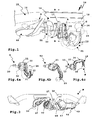
- a hitch 10 includes a vehicle holder 11 and a coupling arm 12 which is movably mounted on the vehicle holder 11.
- the vehicle holder 11 comprises a vehicle bearing part 13 which is fastened with a holder 14 to a motor vehicle 15, for example on a cross member 16.
- the holder 14 comprises, for example, a flange element 17, which is penetrated by the vehicle bearing part 13 or the vehicle Bearing part 13 stops.
- the flange 17 in turn is secured by means of a cross member holder 18 on the cross member 16.
- the cross member holder 18 and / or the flange 17 are, for example, plate-like.
- the cross member 16 may of course also form part of the hitch 10, so that this asylonbauhü or module on the motor vehicle 15 can be fastened.
- the vehicle bearing part 13 comprises a holding section 19 and a bearing section 20.
- the holding section 19 is fastened to the flange element 17 or to the holder 14.
- the bearing portion 20 is for movably supporting the coupling arm 12 which is fixed to a coupling arm bearing part 21.
- the coupling arm bearing part 21 is configured, for example, in the manner of a ring, on the front side of the coupling arm 12 is fastened by means of a particular plate-like mounting portion 22, for example screwed, welded or glued.
- the coupling arm bearing part can form an integral part of a coupling arm, for example, is integral therewith.
- the coupling arm 12 has a curved or arcuate course.
- a curved portion 23 extends away from the mounting portion 22 with a curved course.
- the curved portion 23 is followed by a substantially rectilinear portion 24, which merges into a further curved portion 25 defining a bend of, for example, about 90 °.
- a coupling element 26 for example, a coupling ball or other, for example, polygonal, coupling piece for coupling a trailer (not shown) is provided.
- the coupling arm 12 may preferably be arranged a socket 27, for example at the top of the sections 24, 25.
- the socket 27 is in the Figures 4a-4c not shown.
- a bearing recess 28 is provided, in which the bearing portion 20 is movably received.
- the bearing portion 20 has a substantially spherical or ball-like shape, so that the bearing portion 20 can rotate in the bearing recess 28 in the manner of a ball joint, so a multi-axis rotation of the coupling arm 12 with respect to the vehicle holder 11 is possible.
- the coupling arm 12 is pivotable, for example, about a first axis 30 with respect to the vehicle holder 11 and also also along the axis 30 movable, which will be described below in more detail in connection with the fixation or locking. Further, the coupling arm 12 can be pivoted about a second axis 30 transverse to the axis 31 and / or about a third axis 32, even relatively free in space.
- a positive guide 33 controls the movement of the coupling arm 12 relative to the vehicle holder 11.
- the forced guide 33 includes, for example, a bearing surface 20, quasi the bearing head, the vehicle bearing part 13 provided guide surface 34 on which a movably connected to the coupling arm 12 guide member 35 is guided ,
- the guide member 35 includes, for example, a roller or a bolt, which is fixed or rotatably received in the coupling arm bearing part 21, for example with its longitudinal end portions. The guide member 35 slides or rolls on the guide surface 34 and so the coupling arm 12 before its relative movement to the vehicle holder 11 before.
- an adjusting spring arrangement 36 is optionally also provided, which is supported on the one hand on the vehicle-bearing part 13, on the other hand on the coupling arm bearing part 21.
- the adjusting spring assembly 36 acts on the coupling arm 12, for example in the direction of the non-use position N or the use position G or in an intermediate intermediate position, for example, the lower intermediate position Z2.
- a fixing recess 37 is arranged, in which the guide member 35 engages in a fixing position of the coupling arm 12 relative to the vehicle holder 11.
- the fixing recess 37 forms part of a fixing device 38, which provides for an axial displacement of the coupling arm 12 relative to the vehicle holder 11 at least during a locking movement or fixing movement or the opposite of the same.
- the fixing device 38 comprises an example, rod-like or bolt-like displacement body 39 which is slidably received in a guide 40 of the vehicle-bearing part 13 along a sliding axis, which in the present case corresponds to the axis 30.
- a spring 41 loads the displacer 39 in the direction of a locking position or fixing position, in which the displacer 39 displaces with its front end in guides 42 displacers 43 in particular radially outward, which in turn act on locking elements 44, so that these in front of an outer surface of the coupling arm Projecting bearing 21 and engage in locking receptacles 45 on the coupling arm bearing part 21 in the sense of locking or fixing.
- the fixing device 38 thus locks automatically due to the spring 41.
- an actuator 46 is advantageously provided, which has a motor 47 for driving a Bowden cable 48 which is connected to the displacement body 39.
- the motor 47 thus adjusted to release the fixing device 38, the displacer 39 via the Bowden cable 48 against the force of the spring 41 back so that an inclined surface at the front, free end of the displacer 39 is displaced away from the displacer 43, so that locking elements 44 and the displacement elements 43 in their guides 42 radially inward, at least out of engagement with the locking receptacles 45 can pass.
- the coupling arm bearing part 21 can be slightly removed in the direction of an arrow E from the vehicle bearing part 13, for example as a linear movement, in which case the guide element 35 also comes out of the fixing recess 37. Then the coupling arm bearing part 21 can be moved relative to the bearing section 20 and thus the coupling arm 12 can be adjusted.
- the fixing device 38 is controlled by a controller 49.
- the controller 49 may, for example, a local, in particular in the luggage compartment of the motor vehicle 15 arranged actuating switch, with which the hitch 10 can be actuated, for example, the fixing device 38 can be controlled to release the fixation.
- the controller 49 is electrically connected to a vehicle electrical system, not shown, of the motor vehicle 15 so that it receives there, for example, control signals there.
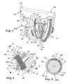
- the hitch 10 is adjustable by means of a drive 60a according to the invention, wherein the drive 60a is a drive for adjusting the coupling arm 12 from the use position G in the non-use position N and vice versa.
- the drive 60a is a drive for adjusting the coupling arm 12 from the use position G in the non-use position N and vice versa.
- the drive 60a is a cable drive, whereby, of course, a belt drive, a Bowden cable or the like are readily possible.
- a Bowden cable is suitable for a difficult installation situation in which the Bowden cable, for example, has to be laid around a component of the trailer coupling, for example a holder or carrier.
- a direct arrangement of the drive 60a in the object to be driven, namely the coupling arm 12 and the coupling arm bearing part 21 is possible, which saves space, on the other hand also allows optimal installation of the cable.
- the drive 60a comprises a drive motor 61, for example an electric motor, which directly or in the present case drives a winding body 63 via a gear 62.
- the drive motor 61, the gear 62 and the winding body 63 are arranged in a protective housing 64, preferably encapsulated.
- the protective housing 64 comprises a sleeve-like protective body 65, which is closed by a lid 66 designed as a kind of cap.
- guide windings 67 are arranged for guiding the cable or the flexible tension member 68a.
- the flexible tension member 68a such as a textile rope, steel rope, carbon fiber rope or the like, guided during winding or unwinding on the winding body 63 and introduced into the respective guide recess of the guide turns 67.
- the guide windings 67 are, for example, helically extending on the outer circumference of the substantially cylindrical Winding body 63 arranged.
- the drive motor 61 drives the winding body 63, so that in each case a run 69 or 70 of the tension member 68 a wound on the winding body 63, that other run 70 or 69 of the tension member 68 a from the winding body 63 is unwound.
- An axis of rotation 72 of the drive 60a expediently runs approximately parallel or, as in the exemplary embodiment, at a small angle, for example approximately 10-30 ° to the axis 30.
- the essentially cylindrical protective housing 64 or the drive assembly is arranged directly next to the vehicle holder 11.
- the drive 60a is fixed relative to the vehicle holder 11.
- the drive 60a is connected to or held by the holder 14.
- the holder 14 has, for example, a holding opening 50.
- the drive 60a is connected via a line 51 to the controller 49.
- the controller 49 drives the drive 60a.
- a sensor 52 is provided to determine a fixing position or a release position of the fixing device 38.
- the sensor 52 is arranged in the region of the displacement body 39 and detects its position.
- the control 49 which accordingly drives the drive motor 61 to move the coupling arm 12 the use position G or the non-use position N is driving.
- a type of alternating operation may preferably be provided, in which the controller 49 drives the drive motor 61 alternately to a clockwise and counterclockwise rotation. It can of course also be provided for each direction of movement, a separate switching input at the controller 49, for example, a push-button switch, in particular in the luggage compartment of the motor vehicle 15th
- the tension member 68a is continuous in the region of the winding body 63. It is looped around the winding body 63 as a whole, in particular with several turns, for which the winding body 63 can exert tensile forces on the pulling member 68a, alternately on the runs 69 or 70, during a rotational movement.
- the free longitudinal ends 73 of the tension member 68a are connected to a drive body 74 tensile strength, but not tensile and stiff, but with a certain amount of play. This game is convenient so that the pulling member 68 a participates in the movements of the drive body 74.
- the drive body 74 is in fact preferably non-rotatable, in another embodiment with a certain slip, but after passing through this slip also rotatably connected to the coupling arm bearing part 21, so that by pulling the tension member 68a of the drive body 74 and with this as the coupling arm -Lagerteil 21 and ultimately also the coupling arm 12 are adjustable, in particular substantially rotatable, but it is clear from the above that the rotational movements of the coupling arm 12 are not only one, but about several axes.
- an axial displaceability (arrow E) with respect to the axis 30 is also present, for example when the fixing device 38 is released and a tensile force is exerted on one of the strands 69 or 70.
- the drive body 74 makes a tilting movement obliquely to the axis 30, which is followed by the pulling member 68a. So that the tension element 68a is guided at least essentially tightly between the winding body 63 and the drive body 74, which constitutes a second winding body 75, a length compensation device 76a is provided.
- the length compensation device 76a is arranged on the drive body 74.
- the length compensation device 76a comprises a holding housing 77, in which the longitudinal ends 73 of the pulling member 68a are received with a length clearance.
- the longitudinal ends 73 are provided with stop bodies 78, the Switzerlandorgan-stops 79 provide.
- the traction stops 79 abut drive stops 80 provided by the retainer 77.
- the pulling member 68a penetrates the holding housing 77 on its end walls, where corresponding passage openings are arranged.
- the cross-sections of these openings are dimensioned so small that the Switzerlandorgan-attacks 79 can strike it.
- the end walls of the holding housing 77 form the drive stops 80th
- the stopper body 78 are, for example, cylinder body, which are fixedly connected to the respective longitudinal ends 73 of the tension member 68 a.
- the longitudinal ends 73 and stop body 78 are completely received in the holding housing 77.
- This also has, for example, a top wall 82 and side walls.
- a respective spring 83 is supported on the outer circumference of the passage openings 81 on the holding housing 77 and on the stop bodies 78 from.
- the stop body 78 connected to the respective run 69 or 70 is pulled in the direction of the associated end wall of the holding housing 77, wherein the spring 83 is compressed.
- the other spring 83 which is arranged on the unloaded or unwinding from the winding body 63 Trum 70 or 69, tensioning the strand 70 or 69, by the arranged on this strand 70 or 69 stop body 78 from the associated drive stop 80 of Holding housing 77 applied away.
- a drive 60b substantially corresponds to the drive 60a, wherein, in contrast to the drive 60a, the tension member 68b is fixed with its longitudinal ends 73 on the drive-side winding body 63, namely by means of holders 84.
- the pulling member 68b of the length compensating device 76b is virtually continuous.
- a portion 90 of the tension member 68b extends between stop bodies 78 which are fixedly connected to the tension member 68b.
- the winding body 75 or the drive body 74 expediently have a larger diameter than the winding body 63 which is arranged in the drive 60a or 60b.
- the drive body 74 makes a rotation of approximately 180 ° when the clutch arm 12 is adjusted between the use position G and the non-use position N through, while the winding body 63 rotates several times.
- the winding body 75 or drive body 74 is expediently ring-shaped or hollow-cylindrical. Conveniently, extend on the outer circumference the winding body 75 guide projections 85, for example, flange-like or annular projections, between which the pulling member 68a or 68b is guided.
- a winding surface 86 extending between the guide projections 85 may, for example, have a good sliding property, be provided with a sliding coating or the like, so that the tension member 68a, 68b tensioned by the length compensating devices 76a, 76b will be slightly attached to the winding surfaces 86 and the outer circumference the winding body 75 can slide along.
- a tension member can be stretched in other ways than in the case of the length compensation devices 76a or 76b: for example, a torsion spring or another, a winding body in the sense of winding loading spring on or in a respective winding body or at the respective Be arranged winding body.
- a torsion spring 87 is provided, which acts on the winding body 63 in the sense of a tensioning of the tension member 68a.
- a tension member can be clamped.
- the drive 60a could be pivotably mounted on the holder 14 by means of a bearing 88.
- a spring 89 acting on a longitudinal end of the protective housing 68 or of the drive 60a acts on the structural unit of the drive 60a in the sense of tensioning the tension element 68a.
Landscapes
- Engineering & Computer Science (AREA)
- Transportation (AREA)
- Mechanical Engineering (AREA)
- Agricultural Machines (AREA)
- Transmission Devices (AREA)
- Vehicle Body Suspensions (AREA)
- Devices For Conveying Motion By Means Of Endless Flexible Members (AREA)
Applications Claiming Priority (1)
| Application Number | Priority Date | Filing Date | Title |
|---|---|---|---|
| DE102011014882A DE102011014882A1 (de) | 2011-03-23 | 2011-03-23 | Anhängekupplung |
Publications (3)
| Publication Number | Publication Date |
|---|---|
| EP2502763A2 true EP2502763A2 (fr) | 2012-09-26 |
| EP2502763A3 EP2502763A3 (fr) | 2013-05-29 |
| EP2502763B1 EP2502763B1 (fr) | 2017-05-10 |
Family
ID=45855474
Family Applications (1)
| Application Number | Title | Priority Date | Filing Date |
|---|---|---|---|
| EP12001999.7A Active EP2502763B1 (fr) | 2011-03-23 | 2012-03-21 | Attelage |
Country Status (2)
| Country | Link |
|---|---|
| EP (1) | EP2502763B1 (fr) |
| DE (1) | DE102011014882A1 (fr) |
Families Citing this family (10)
| Publication number | Priority date | Publication date | Assignee | Title |
|---|---|---|---|---|
| DE102013220024A1 (de) * | 2013-10-02 | 2015-04-02 | Zf Friedrichshafen Ag | Anhängerkupplung für Kraftfahrzeuge |
| DE102015221826A1 (de) * | 2015-11-06 | 2017-05-11 | Bayerische Motoren Werke Aktiengesellschaft | Kraftfahrzeug |
| DE102016119393A1 (de) * | 2016-10-07 | 2018-04-12 | Westfalia-Automotive Gmbh | Anhängekupplung mit einer Anschlussvorrichtung |
| EP3379222B1 (fr) | 2017-03-22 | 2020-12-30 | Methode Electronics Malta Ltd. | Ensemble de capteur à base magnétoélastique |
| US11221262B2 (en) | 2018-02-27 | 2022-01-11 | Methode Electronics, Inc. | Towing systems and methods using magnetic field sensing |
| WO2019168565A1 (fr) | 2018-02-27 | 2019-09-06 | Methode Electronics,Inc. | Systèmes et procédés de remorquage utilisant la détection magnétique |
| US11084342B2 (en) | 2018-02-27 | 2021-08-10 | Methode Electronics, Inc. | Towing systems and methods using magnetic field sensing |
| US11135882B2 (en) | 2018-02-27 | 2021-10-05 | Methode Electronics, Inc. | Towing systems and methods using magnetic field sensing |
| US11491832B2 (en) | 2018-02-27 | 2022-11-08 | Methode Electronics, Inc. | Towing systems and methods using magnetic field sensing |
| DE102022106033A1 (de) * | 2022-03-15 | 2023-09-21 | Westfalia-Automotive Gmbh | Betriebsgerät zum Betreiben einer Anhängekupplung |
Citations (1)
| Publication number | Priority date | Publication date | Assignee | Title |
|---|---|---|---|---|
| DE202004010273U1 (de) | 2004-07-01 | 2004-09-09 | Westfalia-Automotive Gmbh & Co. Kg | Anhängekupplung mit einem Handradmechanismus |
Family Cites Families (16)
| Publication number | Priority date | Publication date | Assignee | Title |
|---|---|---|---|---|
| US4297069A (en) * | 1980-01-02 | 1981-10-27 | Worthington Byron C | Chair carrier |
| US5331722A (en) * | 1991-12-02 | 1994-07-26 | Allen Alexander R | Strap tensioning system |
| DE29712738U1 (de) * | 1997-07-18 | 1997-09-18 | Same Spa | Fernbedienung von Anbauteilen |
| DE19826618C2 (de) * | 1998-06-17 | 2001-05-03 | Peter Rocca | Anhängekupplung |
| DE19902355A1 (de) * | 1999-01-21 | 2000-08-03 | Oris Fahrzeugteile Riehle H | Anhängekupplung |
| DE10144254A1 (de) * | 2001-09-03 | 2003-04-03 | Oris Fahrzeugteile Riehle H | Anhängekupplung |
| US6769858B1 (en) * | 2002-05-09 | 2004-08-03 | Adron E. Butler | Method and apparatus for loading cargo on an ATV |
| DE10231963B4 (de) * | 2002-07-15 | 2006-02-02 | Webasto Ag | Ausziehbarer Lastenträger |
| DE10344863B4 (de) * | 2003-09-26 | 2008-04-17 | Meflex Telecontrol Gmbh & Co. Kg | Fernbetätigung für eine Kraftfahrzeug-Anhängerkupplung |
| DE10347817B4 (de) * | 2003-10-10 | 2014-07-10 | Westfalia-Automotive Gmbh | Anhängekupplung |
| DE102004045859A1 (de) * | 2004-09-20 | 2006-03-23 | Jaeger Cartronix Gmbh | Manueller Antrieb für eine Anhängerkupplung |
| DE202005006751U1 (de) * | 2005-04-26 | 2005-07-07 | Jaeger Cartronix Gmbh | Antrieb für eine Anhängerkupplung |
| DE102006043430B4 (de) * | 2006-09-15 | 2009-12-03 | Jaeger Cartronix Gmbh | Verriegelung für eine Anhängerkupplung |
| DE102006043428A1 (de) * | 2006-09-15 | 2008-03-27 | Jaeger Cartronix Gmbh | Antrieb und Entriegelung für eine Anhängerkupplung |
| US20080149420A1 (en) * | 2006-12-01 | 2008-06-26 | Cheatham Daniel P | Vehicle mountable elevating platform |
| DE102008018739A1 (de) * | 2008-04-14 | 2009-10-15 | Trw Automotive Gmbh | Fahrzeugseitige Kupplungsbaugruppe einer Anhängerkupplung |
-
2011
- 2011-03-23 DE DE102011014882A patent/DE102011014882A1/de not_active Withdrawn
-
2012
- 2012-03-21 EP EP12001999.7A patent/EP2502763B1/fr active Active
Patent Citations (1)
| Publication number | Priority date | Publication date | Assignee | Title |
|---|---|---|---|---|
| DE202004010273U1 (de) | 2004-07-01 | 2004-09-09 | Westfalia-Automotive Gmbh & Co. Kg | Anhängekupplung mit einem Handradmechanismus |
Also Published As
| Publication number | Publication date |
|---|---|
| EP2502763A3 (fr) | 2013-05-29 |
| EP2502763B1 (fr) | 2017-05-10 |
| DE102011014882A1 (de) | 2012-09-27 |
Similar Documents
| Publication | Publication Date | Title |
|---|---|---|
| EP2502763B1 (fr) | Attelage | |
| DE60300967T2 (de) | Seilantriebsanordnung | |
| EP2277724B1 (fr) | Attelage | |
| DE102007040282B4 (de) | Abdeckeinrichtung für den Fahrzeuginnenraum | |
| EP3891042B1 (fr) | Colonne de direction pour un véhicule à moteur | |
| EP2567835B2 (fr) | Attelage | |
| EP2792514B1 (fr) | Attelage | |
| DE102004058738A1 (de) | Hilfsantrieb für einen Anhänger | |
| EP1177948B1 (fr) | Couvercle pour le compartiment de charge d'un véhicule, notamment pour véhicule familial | |
| DE10245458A1 (de) | Betätigungseinrichtung | |
| WO2018219665A1 (fr) | Dispositif d'entraînement conçu pour un siège de véhicule, en particulier un siège de véhicule automobile, et siège de véhicule | |
| WO2015155337A1 (fr) | Dispositif de réglage pour ceinture de sécurité avec élément de guidage de ceinture déployable | |
| DE202005020667U1 (de) | Laderaumabdeckung für ein Kraftfahrzeug | |
| EP1057696B1 (fr) | Dispositif à arceau de sécurité pour véhicules | |
| DE102005048256B4 (de) | Laderaumabdeckung für ein Kraftfahrzeug | |
| WO2016120078A1 (fr) | Dispositif de déplacement permettant un déplacement actionné par une force extérieure d'un capot avant | |
| DE10202914B4 (de) | Ausfahrbarer Ladeboden für ein Fahrzeug | |
| EP2799261A1 (fr) | Attelage | |
| DE10163741C2 (de) | Wickelwellenanordnung für Fahrzeuge mit einer hohlen Wickelwelle zum Aufwickeln einer Werkstoffbahn | |
| DE102006009417B4 (de) | Laderaumabdeckung für ein Kraftfahrzeug | |
| DE4431657C1 (de) | Aufschwenkvorrichtung für eine Kraftfahrzeugklappe | |
| DE102004055359A1 (de) | Schutzvorrichtung für Kraftfahrzeuge | |
| DE20215508U1 (de) | Anhängevorrichtung für Zugfahrzeuge | |
| DE102008033478A1 (de) | Abdeckvorrichtung für einen Gepäckraum eines Kraftfahrzeuges | |
| DE102017209331B4 (de) | Kopfstützeneinzug für einen Fahrzeugsitz, insbesondere Kraftfahrzeugsitz, sowie Fahrzeugsitz |
Legal Events
| Date | Code | Title | Description |
|---|---|---|---|
| PUAI | Public reference made under article 153(3) epc to a published international application that has entered the european phase |
Free format text: ORIGINAL CODE: 0009012 |
|
| AK | Designated contracting states |
Kind code of ref document: A2 Designated state(s): AL AT BE BG CH CY CZ DE DK EE ES FI FR GB GR HR HU IE IS IT LI LT LU LV MC MK MT NL NO PL PT RO RS SE SI SK SM TR |
|
| AX | Request for extension of the european patent |
Extension state: BA ME |
|
| PUAL | Search report despatched |
Free format text: ORIGINAL CODE: 0009013 |
|
| AK | Designated contracting states |
Kind code of ref document: A3 Designated state(s): AL AT BE BG CH CY CZ DE DK EE ES FI FR GB GR HR HU IE IS IT LI LT LU LV MC MK MT NL NO PL PT RO RS SE SI SK SM TR |
|
| AX | Request for extension of the european patent |
Extension state: BA ME |
|
| RIC1 | Information provided on ipc code assigned before grant |
Ipc: B60D 1/26 20060101ALI20130424BHEP Ipc: B60R 9/04 20060101ALI20130424BHEP Ipc: B60D 1/24 20060101ALI20130424BHEP Ipc: B60R 9/06 20060101ALI20130424BHEP Ipc: B60D 1/54 20060101AFI20130424BHEP Ipc: B60D 1/52 20060101ALI20130424BHEP |
|
| 17P | Request for examination filed |
Effective date: 20131113 |
|
| RBV | Designated contracting states (corrected) |
Designated state(s): AL AT BE BG CH CY CZ DE DK EE ES FI FR GB GR HR HU IE IS IT LI LT LU LV MC MK MT NL NO PL PT RO RS SE SI SK SM TR |
|
| GRAP | Despatch of communication of intention to grant a patent |
Free format text: ORIGINAL CODE: EPIDOSNIGR1 |
|
| INTG | Intention to grant announced |
Effective date: 20170125 |
|
| GRAS | Grant fee paid |
Free format text: ORIGINAL CODE: EPIDOSNIGR3 |
|
| GRAA | (expected) grant |
Free format text: ORIGINAL CODE: 0009210 |
|
| AK | Designated contracting states |
Kind code of ref document: B1 Designated state(s): AL AT BE BG CH CY CZ DE DK EE ES FI FR GB GR HR HU IE IS IT LI LT LU LV MC MK MT NL NO PL PT RO RS SE SI SK SM TR |
|
| REG | Reference to a national code |
Ref country code: GB Ref legal event code: FG4D Free format text: NOT ENGLISH |
|
| REG | Reference to a national code |
Ref country code: AT Ref legal event code: REF Ref document number: 891903 Country of ref document: AT Kind code of ref document: T Effective date: 20170515 Ref country code: CH Ref legal event code: EP |
|
| REG | Reference to a national code |
Ref country code: IE Ref legal event code: FG4D Free format text: LANGUAGE OF EP DOCUMENT: GERMAN |
|
| REG | Reference to a national code |
Ref country code: DE Ref legal event code: R096 Ref document number: 502012010269 Country of ref document: DE |
|
| REG | Reference to a national code |
Ref country code: NL Ref legal event code: MP Effective date: 20170510 |
|
| REG | Reference to a national code |
Ref country code: LT Ref legal event code: MG4D |
|
| PG25 | Lapsed in a contracting state [announced via postgrant information from national office to epo] |
Ref country code: HR Free format text: LAPSE BECAUSE OF FAILURE TO SUBMIT A TRANSLATION OF THE DESCRIPTION OR TO PAY THE FEE WITHIN THE PRESCRIBED TIME-LIMIT Effective date: 20170510 Ref country code: GR Free format text: LAPSE BECAUSE OF FAILURE TO SUBMIT A TRANSLATION OF THE DESCRIPTION OR TO PAY THE FEE WITHIN THE PRESCRIBED TIME-LIMIT Effective date: 20170811 Ref country code: FI Free format text: LAPSE BECAUSE OF FAILURE TO SUBMIT A TRANSLATION OF THE DESCRIPTION OR TO PAY THE FEE WITHIN THE PRESCRIBED TIME-LIMIT Effective date: 20170510 Ref country code: LT Free format text: LAPSE BECAUSE OF FAILURE TO SUBMIT A TRANSLATION OF THE DESCRIPTION OR TO PAY THE FEE WITHIN THE PRESCRIBED TIME-LIMIT Effective date: 20170510 Ref country code: ES Free format text: LAPSE BECAUSE OF FAILURE TO SUBMIT A TRANSLATION OF THE DESCRIPTION OR TO PAY THE FEE WITHIN THE PRESCRIBED TIME-LIMIT Effective date: 20170510 Ref country code: NO Free format text: LAPSE BECAUSE OF FAILURE TO SUBMIT A TRANSLATION OF THE DESCRIPTION OR TO PAY THE FEE WITHIN THE PRESCRIBED TIME-LIMIT Effective date: 20170810 |
|
| PG25 | Lapsed in a contracting state [announced via postgrant information from national office to epo] |
Ref country code: IS Free format text: LAPSE BECAUSE OF FAILURE TO SUBMIT A TRANSLATION OF THE DESCRIPTION OR TO PAY THE FEE WITHIN THE PRESCRIBED TIME-LIMIT Effective date: 20170910 Ref country code: NL Free format text: LAPSE BECAUSE OF FAILURE TO SUBMIT A TRANSLATION OF THE DESCRIPTION OR TO PAY THE FEE WITHIN THE PRESCRIBED TIME-LIMIT Effective date: 20170510 Ref country code: LV Free format text: LAPSE BECAUSE OF FAILURE TO SUBMIT A TRANSLATION OF THE DESCRIPTION OR TO PAY THE FEE WITHIN THE PRESCRIBED TIME-LIMIT Effective date: 20170510 Ref country code: BG Free format text: LAPSE BECAUSE OF FAILURE TO SUBMIT A TRANSLATION OF THE DESCRIPTION OR TO PAY THE FEE WITHIN THE PRESCRIBED TIME-LIMIT Effective date: 20170810 Ref country code: SE Free format text: LAPSE BECAUSE OF FAILURE TO SUBMIT A TRANSLATION OF THE DESCRIPTION OR TO PAY THE FEE WITHIN THE PRESCRIBED TIME-LIMIT Effective date: 20170510 Ref country code: PL Free format text: LAPSE BECAUSE OF FAILURE TO SUBMIT A TRANSLATION OF THE DESCRIPTION OR TO PAY THE FEE WITHIN THE PRESCRIBED TIME-LIMIT Effective date: 20170510 Ref country code: RS Free format text: LAPSE BECAUSE OF FAILURE TO SUBMIT A TRANSLATION OF THE DESCRIPTION OR TO PAY THE FEE WITHIN THE PRESCRIBED TIME-LIMIT Effective date: 20170510 |
|
| PG25 | Lapsed in a contracting state [announced via postgrant information from national office to epo] |
Ref country code: EE Free format text: LAPSE BECAUSE OF FAILURE TO SUBMIT A TRANSLATION OF THE DESCRIPTION OR TO PAY THE FEE WITHIN THE PRESCRIBED TIME-LIMIT Effective date: 20170510 Ref country code: RO Free format text: LAPSE BECAUSE OF FAILURE TO SUBMIT A TRANSLATION OF THE DESCRIPTION OR TO PAY THE FEE WITHIN THE PRESCRIBED TIME-LIMIT Effective date: 20170510 Ref country code: CZ Free format text: LAPSE BECAUSE OF FAILURE TO SUBMIT A TRANSLATION OF THE DESCRIPTION OR TO PAY THE FEE WITHIN THE PRESCRIBED TIME-LIMIT Effective date: 20170510 Ref country code: SK Free format text: LAPSE BECAUSE OF FAILURE TO SUBMIT A TRANSLATION OF THE DESCRIPTION OR TO PAY THE FEE WITHIN THE PRESCRIBED TIME-LIMIT Effective date: 20170510 Ref country code: DK Free format text: LAPSE BECAUSE OF FAILURE TO SUBMIT A TRANSLATION OF THE DESCRIPTION OR TO PAY THE FEE WITHIN THE PRESCRIBED TIME-LIMIT Effective date: 20170510 |
|
| REG | Reference to a national code |
Ref country code: DE Ref legal event code: R097 Ref document number: 502012010269 Country of ref document: DE |
|
| REG | Reference to a national code |
Ref country code: FR Ref legal event code: PLFP Year of fee payment: 7 |
|
| PG25 | Lapsed in a contracting state [announced via postgrant information from national office to epo] |
Ref country code: SM Free format text: LAPSE BECAUSE OF FAILURE TO SUBMIT A TRANSLATION OF THE DESCRIPTION OR TO PAY THE FEE WITHIN THE PRESCRIBED TIME-LIMIT Effective date: 20170510 Ref country code: IT Free format text: LAPSE BECAUSE OF FAILURE TO SUBMIT A TRANSLATION OF THE DESCRIPTION OR TO PAY THE FEE WITHIN THE PRESCRIBED TIME-LIMIT Effective date: 20170510 |
|
| PLBE | No opposition filed within time limit |
Free format text: ORIGINAL CODE: 0009261 |
|
| STAA | Information on the status of an ep patent application or granted ep patent |
Free format text: STATUS: NO OPPOSITION FILED WITHIN TIME LIMIT |
|
| 26N | No opposition filed |
Effective date: 20180213 |
|
| PG25 | Lapsed in a contracting state [announced via postgrant information from national office to epo] |
Ref country code: SI Free format text: LAPSE BECAUSE OF FAILURE TO SUBMIT A TRANSLATION OF THE DESCRIPTION OR TO PAY THE FEE WITHIN THE PRESCRIBED TIME-LIMIT Effective date: 20170510 |
|
| PG25 | Lapsed in a contracting state [announced via postgrant information from national office to epo] |
Ref country code: MT Free format text: LAPSE BECAUSE OF FAILURE TO SUBMIT A TRANSLATION OF THE DESCRIPTION OR TO PAY THE FEE WITHIN THE PRESCRIBED TIME-LIMIT Effective date: 20170510 |
|
| REG | Reference to a national code |
Ref country code: CH Ref legal event code: PL |
|
| GBPC | Gb: european patent ceased through non-payment of renewal fee |
Effective date: 20180321 |
|
| PG25 | Lapsed in a contracting state [announced via postgrant information from national office to epo] |
Ref country code: MC Free format text: LAPSE BECAUSE OF FAILURE TO SUBMIT A TRANSLATION OF THE DESCRIPTION OR TO PAY THE FEE WITHIN THE PRESCRIBED TIME-LIMIT Effective date: 20170510 |
|
| REG | Reference to a national code |
Ref country code: BE Ref legal event code: MM Effective date: 20180331 |
|
| REG | Reference to a national code |
Ref country code: IE Ref legal event code: MM4A |
|
| PG25 | Lapsed in a contracting state [announced via postgrant information from national office to epo] |
Ref country code: LU Free format text: LAPSE BECAUSE OF NON-PAYMENT OF DUE FEES Effective date: 20180321 |
|
| PG25 | Lapsed in a contracting state [announced via postgrant information from national office to epo] |
Ref country code: IE Free format text: LAPSE BECAUSE OF NON-PAYMENT OF DUE FEES Effective date: 20180321 |
|
| PG25 | Lapsed in a contracting state [announced via postgrant information from national office to epo] |
Ref country code: CH Free format text: LAPSE BECAUSE OF NON-PAYMENT OF DUE FEES Effective date: 20180331 Ref country code: LI Free format text: LAPSE BECAUSE OF NON-PAYMENT OF DUE FEES Effective date: 20180331 Ref country code: BE Free format text: LAPSE BECAUSE OF NON-PAYMENT OF DUE FEES Effective date: 20180331 Ref country code: GB Free format text: LAPSE BECAUSE OF NON-PAYMENT OF DUE FEES Effective date: 20180321 |
|
| REG | Reference to a national code |
Ref country code: AT Ref legal event code: MM01 Ref document number: 891903 Country of ref document: AT Kind code of ref document: T Effective date: 20180321 |
|
| PG25 | Lapsed in a contracting state [announced via postgrant information from national office to epo] |
Ref country code: AT Free format text: LAPSE BECAUSE OF NON-PAYMENT OF DUE FEES Effective date: 20180321 |
|
| PG25 | Lapsed in a contracting state [announced via postgrant information from national office to epo] |
Ref country code: TR Free format text: LAPSE BECAUSE OF FAILURE TO SUBMIT A TRANSLATION OF THE DESCRIPTION OR TO PAY THE FEE WITHIN THE PRESCRIBED TIME-LIMIT Effective date: 20170510 |
|
| PG25 | Lapsed in a contracting state [announced via postgrant information from national office to epo] |
Ref country code: PT Free format text: LAPSE BECAUSE OF FAILURE TO SUBMIT A TRANSLATION OF THE DESCRIPTION OR TO PAY THE FEE WITHIN THE PRESCRIBED TIME-LIMIT Effective date: 20170510 Ref country code: HU Free format text: LAPSE BECAUSE OF FAILURE TO SUBMIT A TRANSLATION OF THE DESCRIPTION OR TO PAY THE FEE WITHIN THE PRESCRIBED TIME-LIMIT; INVALID AB INITIO Effective date: 20120321 |
|
| PG25 | Lapsed in a contracting state [announced via postgrant information from national office to epo] |
Ref country code: MK Free format text: LAPSE BECAUSE OF NON-PAYMENT OF DUE FEES Effective date: 20170510 Ref country code: CY Free format text: LAPSE BECAUSE OF FAILURE TO SUBMIT A TRANSLATION OF THE DESCRIPTION OR TO PAY THE FEE WITHIN THE PRESCRIBED TIME-LIMIT Effective date: 20170510 |
|
| PG25 | Lapsed in a contracting state [announced via postgrant information from national office to epo] |
Ref country code: AL Free format text: LAPSE BECAUSE OF FAILURE TO SUBMIT A TRANSLATION OF THE DESCRIPTION OR TO PAY THE FEE WITHIN THE PRESCRIBED TIME-LIMIT Effective date: 20170510 |
|
| PGFP | Annual fee paid to national office [announced via postgrant information from national office to epo] |
Ref country code: FR Payment date: 20220203 Year of fee payment: 11 |
|
| PG25 | Lapsed in a contracting state [announced via postgrant information from national office to epo] |
Ref country code: FR Free format text: LAPSE BECAUSE OF NON-PAYMENT OF DUE FEES Effective date: 20230331 |
|
| PGFP | Annual fee paid to national office [announced via postgrant information from national office to epo] |
Ref country code: DE Payment date: 20240327 Year of fee payment: 13 |