EP2502749A2 - Fluid droplet ejection device and ejection inspection method - Google Patents
Fluid droplet ejection device and ejection inspection method Download PDFInfo
- Publication number
- EP2502749A2 EP2502749A2 EP12161016A EP12161016A EP2502749A2 EP 2502749 A2 EP2502749 A2 EP 2502749A2 EP 12161016 A EP12161016 A EP 12161016A EP 12161016 A EP12161016 A EP 12161016A EP 2502749 A2 EP2502749 A2 EP 2502749A2
- Authority
- EP
- European Patent Office
- Prior art keywords
- ejection
- nozzles
- inspection
- nozzle
- fluid droplet
- Prior art date
- Legal status (The legal status is an assumption and is not a legal conclusion. Google has not performed a legal analysis and makes no representation as to the accuracy of the status listed.)
- Withdrawn
Links
- 238000007689 inspection Methods 0.000 title claims abstract description 127
- 239000012530 fluid Substances 0.000 title claims abstract description 99
- 238000000034 method Methods 0.000 title claims description 41
- 238000004140 cleaning Methods 0.000 claims description 22
- 238000001514 detection method Methods 0.000 claims description 3
- 230000008531 maintenance mechanism Effects 0.000 abstract description 9
- 239000000976 ink Substances 0.000 description 60
- 230000007246 mechanism Effects 0.000 description 16
- 230000007547 defect Effects 0.000 description 7
- 230000002950 deficient Effects 0.000 description 6
- 238000012423 maintenance Methods 0.000 description 6
- 230000002745 absorbent Effects 0.000 description 4
- 239000002250 absorbent Substances 0.000 description 4
- 239000002184 metal Substances 0.000 description 3
- 239000003086 colorant Substances 0.000 description 2
- 238000003860 storage Methods 0.000 description 2
- 239000000758 substrate Substances 0.000 description 2
- 238000011109 contamination Methods 0.000 description 1
- 230000003111 delayed effect Effects 0.000 description 1
- 238000007599 discharging Methods 0.000 description 1
- 239000013013 elastic material Substances 0.000 description 1
- 239000007788 liquid Substances 0.000 description 1
- 238000012986 modification Methods 0.000 description 1
- 230000004048 modification Effects 0.000 description 1
- 238000003825 pressing Methods 0.000 description 1
- 238000007789 sealing Methods 0.000 description 1
- 238000004904 shortening Methods 0.000 description 1
- 239000002699 waste material Substances 0.000 description 1
Images





Classifications
-
- B—PERFORMING OPERATIONS; TRANSPORTING
- B41—PRINTING; LINING MACHINES; TYPEWRITERS; STAMPS
- B41J—TYPEWRITERS; SELECTIVE PRINTING MECHANISMS, i.e. MECHANISMS PRINTING OTHERWISE THAN FROM A FORME; CORRECTION OF TYPOGRAPHICAL ERRORS
- B41J2/00—Typewriters or selective printing mechanisms characterised by the printing or marking process for which they are designed
- B41J2/005—Typewriters or selective printing mechanisms characterised by the printing or marking process for which they are designed characterised by bringing liquid or particles selectively into contact with a printing material
- B41J2/01—Ink jet
- B41J2/21—Ink jet for multi-colour printing
- B41J2/2132—Print quality control characterised by dot disposition, e.g. for reducing white stripes or banding
- B41J2/2142—Detection of malfunctioning nozzles
-
- B—PERFORMING OPERATIONS; TRANSPORTING
- B41—PRINTING; LINING MACHINES; TYPEWRITERS; STAMPS
- B41J—TYPEWRITERS; SELECTIVE PRINTING MECHANISMS, i.e. MECHANISMS PRINTING OTHERWISE THAN FROM A FORME; CORRECTION OF TYPOGRAPHICAL ERRORS
- B41J2/00—Typewriters or selective printing mechanisms characterised by the printing or marking process for which they are designed
- B41J2/005—Typewriters or selective printing mechanisms characterised by the printing or marking process for which they are designed characterised by bringing liquid or particles selectively into contact with a printing material
- B41J2/01—Ink jet
- B41J2/015—Ink jet characterised by the jet generation process
- B41J2/04—Ink jet characterised by the jet generation process generating single droplets or particles on demand
- B41J2/045—Ink jet characterised by the jet generation process generating single droplets or particles on demand by pressure, e.g. electromechanical transducers
- B41J2/04501—Control methods or devices therefor, e.g. driver circuits, control circuits
- B41J2/0451—Control methods or devices therefor, e.g. driver circuits, control circuits for detecting failure, e.g. clogging, malfunctioning actuator
-
- B—PERFORMING OPERATIONS; TRANSPORTING
- B41—PRINTING; LINING MACHINES; TYPEWRITERS; STAMPS
- B41J—TYPEWRITERS; SELECTIVE PRINTING MECHANISMS, i.e. MECHANISMS PRINTING OTHERWISE THAN FROM A FORME; CORRECTION OF TYPOGRAPHICAL ERRORS
- B41J2/00—Typewriters or selective printing mechanisms characterised by the printing or marking process for which they are designed
- B41J2/005—Typewriters or selective printing mechanisms characterised by the printing or marking process for which they are designed characterised by bringing liquid or particles selectively into contact with a printing material
- B41J2/01—Ink jet
- B41J2/015—Ink jet characterised by the jet generation process
- B41J2/04—Ink jet characterised by the jet generation process generating single droplets or particles on demand
- B41J2/045—Ink jet characterised by the jet generation process generating single droplets or particles on demand by pressure, e.g. electromechanical transducers
- B41J2/04501—Control methods or devices therefor, e.g. driver circuits, control circuits
- B41J2/04586—Control methods or devices therefor, e.g. driver circuits, control circuits controlling heads of a type not covered by groups B41J2/04575 - B41J2/04585, or of an undefined type
-
- B—PERFORMING OPERATIONS; TRANSPORTING
- B41—PRINTING; LINING MACHINES; TYPEWRITERS; STAMPS
- B41J—TYPEWRITERS; SELECTIVE PRINTING MECHANISMS, i.e. MECHANISMS PRINTING OTHERWISE THAN FROM A FORME; CORRECTION OF TYPOGRAPHICAL ERRORS
- B41J2/00—Typewriters or selective printing mechanisms characterised by the printing or marking process for which they are designed
- B41J2/005—Typewriters or selective printing mechanisms characterised by the printing or marking process for which they are designed characterised by bringing liquid or particles selectively into contact with a printing material
- B41J2/01—Ink jet
- B41J2/135—Nozzles
- B41J2/165—Prevention or detection of nozzle clogging, e.g. cleaning, capping or moistening for nozzles
- B41J2/16579—Detection means therefor, e.g. for nozzle clogging
Definitions
- the present invention relates to a fluid droplet ejection device capable of inspecting fluid ejection from a plurality of ejection nozzles, and to an ejection inspection method.
- JP-A-2008-195037 teaches a printing device the performs a fluid droplet ejection process to check if fluid droplets are ejected normally from the ejection nozzles before printing starts.
- the printer taught in JP-A-2008-195037 inspects ejection from each ejection nozzle formed in the nozzle surface of the printhead, and if an ejection problem is detected in part of the ejection nozzles substitutes other ejection nozzles that are operating normally to eject the liquid that should be ejected from the ejection nozzles that are not operating normally.
- the printer then prints and performs a cleaning process after printing ends to suction ink from the ejection nozzles or wipe the nozzle surface, for example.
- the end of printing is not delayed even if an ejection problem is detected before printing starts because printing can proceed with good results even without first performing a time-consuming cleaning process.
- a problem with this printer is that the ejection inspection process takes a long time because fluid ejection is inspected for every nozzle of the printhead.
- the inspection time could conceivably be shortened by only inspecting a subset of the ejection nozzles in any one inspection operation.
- printing will proceed with some nozzles not ejecting properly, resulting in print defects.
- a fluid droplet ejection device and ejection inspection method according to the present invention enable shortening the time required for one ejection inspection while also minimizing print defects.
- One aspect of the invention is a fluid droplet ejection device including a print unit that prints by ejecting fluid droplets from a plurality of ejection nozzles while moving in a primary scanning direction relative to a print medium; an ejection inspection unit that performs an ejection inspection by inspecting fluid droplet ejection by a group of target nozzles, which are part of an ejection nozzle subset obtained by dividing the plurality of ejection nozzles according to the number of nozzles required to form a smallest printing width in a secondary scanning direction which may be transverse, in particular perpendicular, to the primary scanning direction; and a control unit that controls the print unit and the ejection inspection unit, and changes the group of target nozzles in the ejection nozzle subset and performs the ejection inspection each time a specific amount of printing is completed.
- Another aspect of the invention is an ejection inspection method that, using a print unit that prints by ejecting fluid droplets from a plurality of ejection nozzles while moving in a primary scanning direction relative to a print medium, and an ejection inspection unit that performs an ejection inspection that inspects fluid droplet ejection by a selected group of target nozzles, which are part of an ejection nozzle subset obtained by dividing the plurality of ejection nozzles according to the number of nozzles required to form the smallest printingwidth in the secondary scanning direction, changes the group of target nozzles in the ejection nozzle subset and performs the ejection inspection each time a specific amount of printing is completed.
- an ejection inspection method at a fluid droplet ejection device comprising a print unit that prints by ejecting fluid droplets from a plurality of ejection nozzles while moving in a primary scanning direction relative to a print medium, and an ejection inspection unit that performs an ejection inspection by inspecting fluid droplet ejection of a selected group of target nozzles, which are part of an ejection nozzle subset obtained by dividing the plurality of ejection nozzles according to the number of nozzles required to form a smallest printingwidth in a secondary scanning direction which is transverse, in particular perpendicular, to the primary scanning direction, the method comprising changing the group of target nozzles in the ejection nozzle subset and performing the ejection inspection each time a specific amount of printing is completed.
- ejection is inspected for an ejection nozzle subset of all ejection nozzles in the print unit during a single ejection inspection.
- ejection is inspected for ejection nozzles in a group of nozzles forming at least the smallest printing width in each ejection inspection by changing the nozzles that are included in the nozzle subset that is inspected in each ejection inspection, printing is done at least by inspected ejection nozzles if the nozzles are determined to eject ink and pass inspection, and print defects (dropped dots) can be prevented.
- the smallest printing width may be the smallest line width that the print unit can print.
- the plurality of ejection nozzles are arranged in nozzle lines with the ejection nozzles disposed at a uniform interval, in particular a pitch interval, in the secondary scanning direction, and the nozzle lines are disposed in nozzle line groups of N lines offset by 1/N pitch, in particular by 1/N of the above pitch interval, in the secondary scanning direction;
- the ejection nozzle subset includes two or more ejection nozzles belonging to at least different nozzle lines (i.e. at least two ejection nozzles of the ejection nozzle subset belong to different nozzle lines); and the ejection inspection unit changes the group of target nozzles by nozzle line and performs the ejection inspection.
- the nozzle line groups are determined by fluid droplet type; the reference position of nozzle lines 1 to N arranged according to the amount of offset of the nozzle line groups is the same position in the secondary scanning direction regardless of the fluid droplet type; and the ejection inspection unit selects a nozzle line in the secondary scanning direction of a different line number for each fluid droplet type as the group of target nozzles in one ejection inspection.
- this aspect of the invention inspects fluid ejection for ejection nozzles that discharge at the same ejection position during every ejection inspection. As a result, printing is done at least by inspected ejection nozzles if the nozzles are determined to eject ink and pass inspection, and dropped dots can be prevented at the ejection position.
- a cleaning unit cleans the print unit when more than a specific number of ejection nozzles fail inspection during a specific number of ejection inspections.
- the print unit reprints the immediately preceding content after cleaning is performed.
- This aspect of the invention is particularly convenient for the user because printing repeats automatically when a print defect occurs while printing.
- the ejection inspection unit includes an ejection drive unit that causes the print unit to eject charged fluid droplets from the ejection nozzles, an ejection target on which the charged fluid droplets that were ejected land, and a detection unit that detects change in current produced in the ejection target when the charged fluid droplets land, and determines ejection from the ejection nozzles based on change in the current.
- a fluid droplet ejection device is a printing device that prints in color by ejecting different colors of ink (fluid droplets) onto roll paper used as the print medium, and inspects fluid ejection from the fluid droplet ejection head each time a specific amount of printing has been completed.
- a widthwise direction with respect to the width of the roll paper loaded in the fluid droplet ejection device is referred to herein as the primary scanning direction
- a lengthwise direction with respect to the length of the roll paper is referred to herein as the secondary scanning direction (see FIG. 1 ).
- the fluid droplet ejection device 1 includes: a roll paper compartment 3 that holds roll paper 2; a carriage 5 that carries a fluid droplet ejection head 4 (print unit) that ejects plural different inks onto the roll paper 2; a carriage moving mechanism 6 that moves the carriage 5 in the primary scanning direction; a roll paper conveyance mechanism 7 that pulls the end of the roll paper 2 out in the secondary scanning direction; an ink supply mechanism 8 that supplies color ink to the fluid droplet ejection head 4; a maintenance mechanism 9 that performs maintenance of the fluid droplet ejection head 4; and a control unit (not shown) that controls operation of these other parts; and is covered by a case (not shown).
- the fluid droplet ejection device 1 also has a roll paper cover (not shown) for removably loading roll paper 2 into the roll paper compartment 3, and a cartridge cover 11 for removably installing the ink cartridges 10 of the ink supply mechanism 8.
- the carriage moving mechanism 6 includes a guide shaft 12 that supports the carriage 5 movably in the primary scanning direction, an endless belt 13 disposed with the guide shaft 12, and a carriage motor 14 that causes the belt 13 to rotate.
- the carriage moving mechanism 6 drives the carriage motor 14 to turn the belt 13 and move the carriage 5 in the primary scanning direction along the guide shaft 12.
- the roll paper conveyance mechanism 7 includes a platen 15 disposed above the roll paper 2 opposite the carriage 5, and a paper feed roller 16 that conveys the end of the roll paper 2 passing thereabove in the secondary scanning direction.
- the platen 15 pushes the roll paper 2 against the fluid droplet ejection head 4 mounted on the carriage 5, and the paper feed roller 16 conveys and discharges the printed roll paper 2 while pressing the roll paper 2 to the carriage side.
- the ink supply mechanism 8 includes an ink cartridge 10 loaded in the ink cartridge loading unit 17, and an ink channel 18 and ink supply tube 19 for supplying color ink to the fluid droplet ejection head 4 from ink packs for each color of ink stored in the ink cartridge 10.
- This embodiment of the invention uses ink packs and ink supply tubes 19 for three colors of ink, cyan (C), magenta (M), and yellow (Y) ink.
- the maintenance mechanism 9 has a head cap 21 ( FIG. 5 ) for sealing the nozzle surface 20 of the fluid droplet ejection head 4, an ink suction mechanism, and a wiper mechanism (both not shown) disposed opposite the carriage 5 at a position removed in the primary scanning direction from above the roll paper 2.
- a tube from the ink suction mechanism is connected to the head cap 21, and the pressure inside the head cap 21 is reduced so that color ink is suctioned from the ejection nozzles N formed in the nozzle surface 20 by driving the pump motor of the ink suction mechanism.
- the wiper mechanism wipes contamination from the nozzle surface 20 by, for example, using a rubber wiper.
- the maintenance mechanism 9 applies a cleaning process to the fluid droplet ejection head 4 by performing the ink suction process of the ink suction mechanism and the wiping process of the wiper mechanism. Note that the maintenance mechanism 9 performs the cleaning process after inspecting fluid ejection from the fluid droplet ejection head 4 (further described below) if an ejection problem is found in the ejection inspection.
- the fluid droplet ejection device 1 moves the carriage 5 to the printing position P1 for printing, and moves the carriage 5 to the maintenance position P2 for maintenance of the fluid droplet ejection head 4.
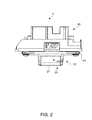
- the fluid droplet ejection head 4 exemplarily is a six-channel inkjet head, and has an ink inlet unit 23 with six connection needles 22; a head substrate 24 connected to the ink inlet unit 23; and a printhead 25 that is connected to the head substrate 24 and ejects ink.
- the ink inlet unit 23 exemplarily has six connection needles 22A to 22F corresponding to the six nozzle lines NLA to NLF, and ink is supplied thereto from the ink supply mechanism 8. Note that the correlation between the connection needles 22 and the nozzle lines NL is as shown in FIG. 3 .
- the printhead 25 also has six pump units 26 rendered by piezoelectric devices, for example, and a nozzle plate 27 with a nozzle surface 20 in which a plurality of ejection nozzles N are formed.
- the fluid droplet ejection device 1 ejects color ink from the ejection nozzles N by applying the drive signals output from a control device to each pump unit 26.
- FIG. 4A schematically describes the arrangement of the ejection nozzles N formed in the nozzle surface 20 of the nozzle plate 27. Note that this figure shows the nozzle plate 27 rotated 180 degrees from FIG. 3 . As shown in the figure, the numerous ejection nozzles N formed in the nozzle surface 20 of the nozzle plate 27 are arranged in six nozzle lines NLA to NLF. Each nozzle line NL exemplarily has 90 ejection nozzles N1 to N90 arrayed at a uniform pitch (nozzle pitch) in the secondary scanning direction.
- the nozzle lines NL are formed with three nozzle lines NLA, NLC, NLE disposed to reference position 1, and three nozzle lines NLB, NLD, NLF disposed to reference position 2, which is offset 1/2 nozzle pitch in the secondary scanning direction from reference position 1.
- the nozzle lines NL are thus formed mutually parallel and offset a half nozzle pitch.
- FIG. 4B shows the color of ink ejected from each nozzle line NL.
- nozzle lines NLA and NLF eject cyan (C) nozzle lines NLB and NLE eject magenta (M), and nozzle lines NLC and NLD eject yellow (Y). More specifically, each color of ink is ejected from two nozzle lines NL at different reference positions, i.e. from two nozzle lines NL which are offset a half nozzle pitch with respect to each other in the secondary scanning direction.
- nozzle line group as described in the accompanying claims is exemplarily embodied here by the nozzle lines NLA and NLF, nozzle lines NLB and NLE, and nozzle lines NLC and NLD that eject the same color of ink.
- the fluid droplet ejection head 4 prints the smallest printing width (smallest line width) in the secondary scanning direction by ejecting ink from the six ejection nozzles N (nozzle subgroup) composed of the same n-th ejection nozzles N in each nozzle line NL counted from the downstream end in the roll paper conveyance direction.
- the smallest printing width is the thinnest line that the fluid droplet ejection device 1 can print. For example, as shown in FIG. 4A , the smallest printing width at the furthest downstream position of the print area is printed by the six ejection nozzles N1A, N1B, N1C, N1D, N1E, N1F.
- the fluid droplet ejection head 4 is thus configured to print the smallest printing width by means of plural ejection nozzles with a gap of a half nozzle pitch therebetween.
- the fluid droplet ejection head 4 prints in color by moving in the primary scanning direction while the ejection nozzles N with the same nozzle number in each nozzle line NL of the same reference position eject a different color of ink at the same position.
- FIG. 5 is a section view of the head cap 21 of the maintenance mechanism 9.
- the head cap 21 has a lip 28 made of rubber or other elastic material that can fit tight to the nozzle surface 20; a box-like cap body 29 with an opening that is large enough to seal the nozzle surface 20 of the fluid droplet ejection head 4; a multilayer absorbent sponge 31 that absorbs waste ink contained in the recess 30 of the cap body 29; a metal shaft 32 that is electrically conductive with the absorbent sponge 31 and stands inside the recess 30 of the cap body 29; and a lead 33 connected to the bottom end of the metal shaft 32.
- the absorbent sponge 31 is disposed with a gap to the lip 28.
- the maintenance mechanism 9 inspects the ink ejection state of ejection nozzles N of the fluid droplet ejection head 4 each time printing (unit printing) based on print data units, which are created by dividing all print data into units of a specific size, ends.
- This ejection inspection first positions the head cap 21 opposite the nozzle surface 20 of the fluid droplet ejection head 4, and then selectively discharges charged ink from a plurality of ejection nozzles N (ejection drive unit). Change in the current produced when the charged ink that is ejected lands on the absorbent sponge 31 (ejection target) is then detected through the metal shaft 32 and lead 33 (detection unit), and a control unit determines if fluid was ejected.
- the ejection inspection is performed once for a plurality of ejection nozzles N, and the result of the ejection inspection is "fail” (defective fluid ejection) if the number of ejection nozzles N determined to have not ejected ink in the group of tested ejection nozzles N exceeds a specific number, and the result is "pass” (good fluid ejection) if the number of ejection nozzles N determined to have not ejected ink is within this specific number.
- the ejection inspection unit in the accompanying claims is rendered by the control unit and maintenance mechanism 9.
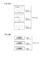
- the print data is divided into the individual pages (formed each time the roll paper is cut) in which the print data for a single continuous job is printed, and each page is one unit of print data (print data unit).
- the content of each print data unit is different in this case.
- the total print data consists of print data of the same content being repeated plural times. The content of each print data unit is the same in this case.
- the control unit of the fluid droplet ejection device 1 changes the ejection nozzles N for which ejection is inspected in the ejection inspection by nozzle line NL. More specifically, the fluid droplet ejection device 1 changes the nozzle line NL to be inspected in each ejection inspection.
- FIG. 7 shows three patterns in which the ejection nozzles N change in each ejection inspection.
- pattern 1 shown in FIG. 7A ejection by the three nozzle lines NLA, NLC, NLE referenced to reference position 1 is inspected in the first ejection inspection.
- the second ejection inspection ejection by the three nozzle lines NLB, NLD, NLF referenced to reference position 2 is inspected. Ejection nozzles N that eject each color of ink at the same reference position are thus inspected in each ejection inspection with pattern 1.
- At least one ejection nozzle N discharging each color of ink that is part of the same group of ejection nozzles N used to form the smallest printing width can be inspected in every ejection inspection. Therefore, by performing the cleaning process when inspection fails and reprinting the immediately preceding print unit, dropout can be prevented without inspecting all ejection nozzles N in every ejection inspection.
- the nozzle lines NLA and NLC that are disposed to reference position 1 and eject cyan ink and yellow ink, and the nozzle line NLB disposed to reference position 2 that ejects magenta ink, are inspected in the first ejection inspection.
- the remaining nozzle lines NLD, NLE, NLF are then inspected in the second ejection inspection.
- the nozzle line NLA that is disposed to reference position 1 and ejects cyan ink, and the nozzle lines NLB and NLD disposed to reference position 2 that eject magenta ink and yellow ink are inspected in the first ejection inspection.
- nozzle lines NLC, NLE, NLF are then inspected in the second ejection inspection.
- Patterns 2 and 3 thus inspect the nozzle lines NL that eject cyan and magenta and are disposed at different reference positions in the first ejection inspection. As a result, dropout of black dots, which are primarily affected by ejection of cyan and magenta, can be prevented at the ejection positions on one of the reference positions.
- the fluid droplet ejection device 1 including the ejection inspection is described next with reference to FIG. 8 .
- the plural ejection nozzles N inspected in the first ejection inspection are referred to as "inspection target 1" and the plural ejection nozzles N inspected in the second ejection inspection are referred to as "inspection target 2" below.
- black dots (•) in the figure denote good nozzles that eject normally, and arrows with solid lines indicate that printing (ejection) occurs with the inspection target ejecting normally.
- Open circles (o) denote defective nozzles that are not ejecting normally, and arrows with a dotted line indicate that printing (ejection) occurs with the inspection target not ejecting normally (defective ink ejection). Note that if printing proceeds with either inspection target 1 or inspection target 2 ejecting normally while printing, printing results in a good printout. However, if printing occurs with inspection target 1 and inspection target 2 not ejecting ink normally (defective ejection), the likelihood of dropped dots occurring while printing is high and the printout will be defective. Also note that CN denotes a cleaning process.
- FIGS. 8A and8B show cases in which inspection failed due to defective ejection in the first ejection inspection.
- the fluid droplet ejection device 1 After printing the first print data unit (print unit 1), the fluid droplet ejection device 1 performs the first ejection inspection (ejection inspection 1), and then performs the cleaning process based on inspection failing.
- Print unit 1 is then printed again (reprint 1). Because the likelihood of a print defect in print unit 1 is high if the first ejection inspection fails and inspection target 2, which was not inspected in the first ejection inspection, is not ejecting normally ( FIG. 8A ), the print data unit can be reprinted effectively by performing the cleaning process and reprint 1.
- FIGS. 8C and 8D show a case in which the first ejection inspection passed.
- the fluid droplet ejection device 1 performs ejection inspection 1, and based on the inspection result of pass prints the next print data unit (print unit 2).
- the inspection target 2 that was not inspected in the first ejection inspection is not ejecting normally at this time as shown in FIG. 8D , printing is completed with good results by means of the plural ejection nozzles N in the inspection target 1 that passed inspection.
- a result of fail can be obtained for inspection target 2 in ejection inspection 2 performed after printing unit 2.
- the printing process of the fluid droplet ejection device 1 is described next with reference to the flow chart in FIG. 9 .
- the fluid droplet ejection device 1 first prints the first print data unit (S01), and then applies the ejection inspection to the fluid droplet ejection head 4 (S02). If the inspection fails (S03 returns FAIL), the cleaning process is applied to the fluid droplet ejection head 4 (S04). The print data unit that was just printed is then reprinted (S05). However, if the inspection passes (S03 returns PASS) and printing all print data is completed (S06 returns Yes), the process ends. If printing all print data is not completed (S06 returns No), the next print data unit is printed (S07). The group of nozzles inspected in the last ejection inspection is then changed (S08) and the next group of nozzles is inspected (S02). Steps S02 to S08 repeat thereafter.
- the ejection inspection method of the fluid droplet ejection device 1 changes the group of nozzles to be inspected within the plurality of ejection nozzles N that form the smallest printing width every time a specific amount of printing is completed, the time required for each ejection inspection can be shortened and dropped dots can be prevented. The time required for the complete printing process can therefore be shortened.
- the cleaning process is applied to the fluid droplet ejection head 4 only when ejection inspection fails, the number of times the cleaning process is performed can be reduced, and the amount of ink consumed without printing can be reduced.
- the number of fluid droplet ejection heads 4 in the fluid droplet ejection device 1, the number of ejection nozzles N, the number of nozzle lines NL, and the number of different inks can also be determined as desired.
- the print medium is also not limited to continuous paper as described above, and the invention can also be used with cut sheet media.
- Elements of the fluid droplet ejection device 1 described above can also be provided as a program.
- the program can also be supplied stored on a storage medium (not shown in the figure). Examples of such storage media include CD-ROM, flash ROM, memory cards (Compact Flash (R), smart media, and memory sticks, for example), CDs, magneto-optical media, DVDs, and floppy disks.
Landscapes
- Engineering & Computer Science (AREA)
- Quality & Reliability (AREA)
- Ink Jet (AREA)
- Particle Formation And Scattering Control In Inkjet Printers (AREA)
Abstract
Description
- The present invention relates to a fluid droplet ejection device capable of inspecting fluid ejection from a plurality of ejection nozzles, and to an ejection inspection method.
- Japanese Unexamined Patent Appl. Pub.
JP-A-2008-195037 JP-A-2008-195037 - A problem with this printer, however, is that the ejection inspection process takes a long time because fluid ejection is inspected for every nozzle of the printhead. The inspection time could conceivably be shortened by only inspecting a subset of the ejection nozzles in any one inspection operation. However, if there is an ejection problem in any of the nozzles that are not in the group of inspected nozzles, printing will proceed with some nozzles not ejecting properly, resulting in print defects.
- A fluid droplet ejection device and ejection inspection method according to the present invention enable shortening the time required for one ejection inspection while also minimizing print defects.
- One aspect of the invention is a fluid droplet ejection device including a print unit that prints by ejecting fluid droplets from a plurality of ejection nozzles while moving in a primary scanning direction relative to a print medium; an ejection inspection unit that performs an ejection inspection by inspecting fluid droplet ejection by a group of target nozzles, which are part of an ejection nozzle subset obtained by dividing the plurality of ejection nozzles according to the number of nozzles required to form a smallest printing width in a secondary scanning direction which may be transverse, in particular perpendicular, to the primary scanning direction; and a control unit that controls the print unit and the ejection inspection unit, and changes the group of target nozzles in the ejection nozzle subset and performs the ejection inspection each time a specific amount of printing is completed.
- Another aspect of the invention is an ejection inspection method that, using a print unit that prints by ejecting fluid droplets from a plurality of ejection nozzles while moving in a primary scanning direction relative to a print medium, and an ejection inspection unit that performs an ejection inspection that inspects fluid droplet ejection by a selected group of target nozzles, which are part of an ejection nozzle subset obtained by dividing the plurality of ejection nozzles according to the number of nozzles required to form the smallest printingwidth in the secondary scanning direction, changes the group of target nozzles in the ejection nozzle subset and performs the ejection inspection each time a specific amount of printing is completed. In particular, there is proposed an ejection inspection method at a fluid droplet ejection device comprising a print unit that prints by ejecting fluid droplets from a plurality of ejection nozzles while moving in a primary scanning direction relative to a print medium, and an ejection inspection unit that performs an ejection inspection by inspecting fluid droplet ejection of a selected group of target nozzles, which are part of an ejection nozzle subset obtained by dividing the plurality of ejection nozzles according to the number of nozzles required to form a smallest printingwidth in a secondary scanning direction which is transverse, in particular perpendicular, to the primary scanning direction, the method comprising changing the group of target nozzles in the ejection nozzle subset and performing the ejection inspection each time a specific amount of printing is completed.
- These aspects of the invention can shorten the time required for an ejection inspection because ejection is inspected for an ejection nozzle subset of all ejection nozzles in the print unit during a single ejection inspection. In addition, because ejection is inspected for ejection nozzles in a group of nozzles forming at least the smallest printing width in each ejection inspection by changing the nozzles that are included in the nozzle subset that is inspected in each ejection inspection, printing is done at least by inspected ejection nozzles if the nozzles are determined to eject ink and pass inspection, and print defects (dropped dots) can be prevented.
Note that the smallest printing width may be the smallest line width that the print unit can print. - Further preferably, the plurality of ejection nozzles are arranged in nozzle lines with the ejection nozzles disposed at a uniform interval, in particular a pitch interval, in the secondary scanning direction, and the nozzle lines are disposed in nozzle line groups of N lines offset by 1/N pitch, in particular by 1/N of the above pitch interval, in the secondary scanning direction; the ejection nozzle subset includes two or more ejection nozzles belonging to at least different nozzle lines (i.e. at least two ejection nozzles of the ejection nozzle subset belong to different nozzle lines); and the ejection inspection unit changes the group of target nozzles by nozzle line and performs the ejection inspection.
- By changing the ejection nozzles to be inspected by nozzle line, controlling driving the print unit during the ejection inspection can be simplified.
- Yet further preferably, the nozzle line groups are determined by fluid droplet type; the reference position of
nozzle lines 1 to N arranged according to the amount of offset of the nozzle line groups is the same position in the secondary scanning direction regardless of the fluid droplet type; and the ejection inspection unit selects a nozzle line in the secondary scanning direction of a different line number for each fluid droplet type as the group of target nozzles in one ejection inspection. - When ejection nozzles in different nozzle groups in the primary scanning direction can print as desired (such as a desired color) by ejecting different fluid droplets at the same ejection position at different times by the print unit moving in the primary scanning direction, this aspect of the invention inspects fluid ejection for ejection nozzles that discharge at the same ejection position during every ejection inspection. As a result, printing is done at least by inspected ejection nozzles if the nozzles are determined to eject ink and pass inspection, and dropped dots can be prevented at the ejection position.
- In another aspect of the invention, a cleaning unit cleans the print unit when more than a specific number of ejection nozzles fail inspection during a specific number of ejection inspections.
- Because cleaning is performed in this aspect of the invention only when there are actually nozzles that are not ejecting, the time used for the maintenance process during the printing process can be shortened.
- In another aspect of the invention the print unit reprints the immediately preceding content after cleaning is performed.
- This aspect of the invention is particularly convenient for the user because printing repeats automatically when a print defect occurs while printing.
- In another aspect of the invention the ejection inspection unit includes an ejection drive unit that causes the print unit to eject charged fluid droplets from the ejection nozzles, an ejection target on which the charged fluid droplets that were ejected land, and a detection unit that detects change in current produced in the ejection target when the charged fluid droplets land, and determines ejection from the ejection nozzles based on change in the current.
- Because the quantity of fluid consumed by ejection inspection is minimal, this aspect of the invention can suppress consumption of fluid required for maintenance instead of printing.
Other objects and attainments together with a fuller understanding of the invention will become apparent and appreciated by referring to the following description and claims taken in conjunction with the accompanying drawings. -
-
FIG. 1 is an exemplary oblique view of a fluid droplet ejection device according to a preferred embodiment of the invention. -
FIG. 2 is an exemplary external side view of the fluid droplet ejection head. -
FIG. 3A is an exemplary plan view of the fluid droplet ejection head from the ink supply side, andFIG. 3B is an exemplary plan view from the nozzle surface side. -
FIG. 4A schematically and exemplarily describes the arrangement of the ejection nozzles on the nozzle surface, andFIG. 4B is an exemplary table showing the types of ink ejected from each nozzle line. -
FIG. 5 is an exemplary section view of the head cap. -
FIG. 6 exemplarily illustrates print data units. -
FIG. 7 shows an exemplary selection pattern for the nozzle line to be inspected. -
FIG. 8 exemplarily describes the printing process schedule. -
FIG. 9 is an exemplary flow chart of the printing process. - A preferred embodiment of a fluid droplet ejection device and ejection inspection method according to the present invention is described below with reference to the accompanying figures. A fluid droplet ejection device according to the invention is a printing device that prints in color by ejecting different colors of ink (fluid droplets) onto roll paper used as the print medium, and inspects fluid ejection from the fluid droplet ejection head each time a specific amount of printing has been completed. Note that a widthwise direction with respect to the width of the roll paper loaded in the fluid droplet ejection device is referred to herein as the primary scanning direction, and a lengthwise direction with respect to the length of the roll paper is referred to herein as the secondary scanning direction (see
FIG. 1 ). - As shown in
FIG. 1 , the fluiddroplet ejection device 1 according to this embodiment of the invention includes: aroll paper compartment 3 that holdsroll paper 2; acarriage 5 that carries a fluid droplet ejection head 4 (print unit) that ejects plural different inks onto theroll paper 2; acarriage moving mechanism 6 that moves thecarriage 5 in the primary scanning direction; a rollpaper conveyance mechanism 7 that pulls the end of theroll paper 2 out in the secondary scanning direction; anink supply mechanism 8 that supplies color ink to the fluiddroplet ejection head 4; amaintenance mechanism 9 that performs maintenance of the fluiddroplet ejection head 4; and a control unit (not shown) that controls operation of these other parts; and is covered by a case (not shown). The fluiddroplet ejection device 1 also has a roll paper cover (not shown) for removably loadingroll paper 2 into theroll paper compartment 3, and acartridge cover 11 for removably installing theink cartridges 10 of theink supply mechanism 8. - The
carriage moving mechanism 6 includes aguide shaft 12 that supports thecarriage 5 movably in the primary scanning direction, anendless belt 13 disposed with theguide shaft 12, and acarriage motor 14 that causes thebelt 13 to rotate. Thecarriage moving mechanism 6 drives thecarriage motor 14 to turn thebelt 13 and move thecarriage 5 in the primary scanning direction along theguide shaft 12. - The roll
paper conveyance mechanism 7 includes aplaten 15 disposed above theroll paper 2 opposite thecarriage 5, and apaper feed roller 16 that conveys the end of theroll paper 2 passing thereabove in the secondary scanning direction. Theplaten 15 pushes theroll paper 2 against the fluiddroplet ejection head 4 mounted on thecarriage 5, and thepaper feed roller 16 conveys and discharges the printedroll paper 2 while pressing theroll paper 2 to the carriage side. - The
ink supply mechanism 8 includes anink cartridge 10 loaded in the inkcartridge loading unit 17, and anink channel 18 andink supply tube 19 for supplying color ink to the fluiddroplet ejection head 4 from ink packs for each color of ink stored in theink cartridge 10. This embodiment of the invention uses ink packs andink supply tubes 19 for three colors of ink, cyan (C), magenta (M), and yellow (Y) ink. - The
maintenance mechanism 9 has a head cap 21 (FIG. 5 ) for sealing thenozzle surface 20 of the fluiddroplet ejection head 4, an ink suction mechanism, and a wiper mechanism (both not shown) disposed opposite thecarriage 5 at a position removed in the primary scanning direction from above theroll paper 2. One end of a tube from the ink suction mechanism is connected to thehead cap 21, and the pressure inside thehead cap 21 is reduced so that color ink is suctioned from the ejection nozzles N formed in thenozzle surface 20 by driving the pump motor of the ink suction mechanism. The wiper mechanism wipes contamination from thenozzle surface 20 by, for example, using a rubber wiper.
Themaintenance mechanism 9 applies a cleaning process to the fluiddroplet ejection head 4 by performing the ink suction process of the ink suction mechanism and the wiping process of the wiper mechanism. Note that themaintenance mechanism 9 performs the cleaning process after inspecting fluid ejection from the fluid droplet ejection head 4 (further described below) if an ejection problem is found in the ejection inspection. - Note that the position where the
carriage 5 is opposite theroll paper 2 is the printing position P1, and the position where thecarriage 5 is opposite themaintenance mechanism 9 is the maintenance position P2. The fluiddroplet ejection device 1 moves thecarriage 5 to the printing position P1 for printing, and moves thecarriage 5 to the maintenance position P2 for maintenance of the fluiddroplet ejection head 4. - As shown in
FIG. 2 andFIG. 3 , the fluiddroplet ejection head 4 exemplarily is a six-channel inkjet head, and has anink inlet unit 23 with six connection needles 22; ahead substrate 24 connected to theink inlet unit 23; and aprinthead 25 that is connected to thehead substrate 24 and ejects ink. Theink inlet unit 23 exemplarily has sixconnection needles 22A to 22F corresponding to the six nozzle lines NLA to NLF, and ink is supplied thereto from theink supply mechanism 8. Note that the correlation between the connection needles 22 and the nozzle lines NL is as shown inFIG. 3 .
Theprinthead 25 also has sixpump units 26 rendered by piezoelectric devices, for example, and anozzle plate 27 with anozzle surface 20 in which a plurality of ejection nozzles N are formed. The fluiddroplet ejection device 1 ejects color ink from the ejection nozzles N by applying the drive signals output from a control device to eachpump unit 26. -
FIG. 4A schematically describes the arrangement of the ejection nozzles N formed in thenozzle surface 20 of thenozzle plate 27. Note that this figure shows thenozzle plate 27 rotated 180 degrees fromFIG. 3 . As shown in the figure, the numerous ejection nozzles N formed in thenozzle surface 20 of thenozzle plate 27 are arranged in six nozzle lines NLA to NLF. Each nozzle line NL exemplarily has 90 ejection nozzles N1 to N90 arrayed at a uniform pitch (nozzle pitch) in the secondary scanning direction. The nozzle lines NL are formed with three nozzle lines NLA, NLC, NLE disposed to referenceposition 1, and three nozzle lines NLB, NLD, NLF disposed to referenceposition 2, which is offset 1/2 nozzle pitch in the secondary scanning direction fromreference position 1. The nozzle lines NL are thus formed mutually parallel and offset a half nozzle pitch. -
FIG. 4B shows the color of ink ejected from each nozzle line NL. As shown in the figure, nozzle lines NLA and NLF eject cyan (C), nozzle lines NLB and NLE eject magenta (M), and nozzle lines NLC and NLD eject yellow (Y). More specifically, each color of ink is ejected from two nozzle lines NL at different reference positions, i.e. from two nozzle lines NL which are offset a half nozzle pitch with respect to each other in the secondary scanning direction.
Note that a "nozzle line group" as described in the accompanying claims is exemplarily embodied here by the nozzle lines NLA and NLF, nozzle lines NLB and NLE, and nozzle lines NLC and NLD that eject the same color of ink. - The fluid
droplet ejection head 4 prints the smallest printing width (smallest line width) in the secondary scanning direction by ejecting ink from the six ejection nozzles N (nozzle subgroup) composed of the same n-th ejection nozzles N in each nozzle line NL counted from the downstream end in the roll paper conveyance direction.
The smallest printing width is the thinnest line that the fluiddroplet ejection device 1 can print. For example, as shown inFIG. 4A , the smallest printing width at the furthest downstream position of the print area is printed by the six ejection nozzles N1A, N1B, N1C, N1D, N1E, N1F. The fluiddroplet ejection head 4 is thus configured to print the smallest printing width by means of plural ejection nozzles with a gap of a half nozzle pitch therebetween. The fluiddroplet ejection head 4 prints in color by moving in the primary scanning direction while the ejection nozzles N with the same nozzle number in each nozzle line NL of the same reference position eject a different color of ink at the same position. -
FIG. 5 is a section view of thehead cap 21 of themaintenance mechanism 9. As shown in the figure, thehead cap 21 has alip 28 made of rubber or other elastic material that can fit tight to thenozzle surface 20; a box-like cap body 29 with an opening that is large enough to seal thenozzle surface 20 of the fluiddroplet ejection head 4; a multilayerabsorbent sponge 31 that absorbs waste ink contained in therecess 30 of thecap body 29; ametal shaft 32 that is electrically conductive with theabsorbent sponge 31 and stands inside therecess 30 of thecap body 29; and a lead 33 connected to the bottom end of themetal shaft 32. Theabsorbent sponge 31 is disposed with a gap to thelip 28. - The
maintenance mechanism 9 inspects the ink ejection state of ejection nozzles N of the fluiddroplet ejection head 4 each time printing (unit printing) based on print data units, which are created by dividing all print data into units of a specific size, ends.
This ejection inspection first positions thehead cap 21 opposite thenozzle surface 20 of the fluiddroplet ejection head 4, and then selectively discharges charged ink from a plurality of ejection nozzles N (ejection drive unit). Change in the current produced when the charged ink that is ejected lands on the absorbent sponge 31 (ejection target) is then detected through themetal shaft 32 and lead 33 (detection unit), and a control unit determines if fluid was ejected.
The ejection inspection is performed once for a plurality of ejection nozzles N, and the result of the ejection inspection is "fail" (defective fluid ejection) if the number of ejection nozzles N determined to have not ejected ink in the group of tested ejection nozzles N exceeds a specific number, and the result is "pass" (good fluid ejection) if the number of ejection nozzles N determined to have not ejected ink is within this specific number.
Note that the ejection inspection unit in the accompanying claims is rendered by the control unit andmaintenance mechanism 9. - Dividing the print data into print data units in this embodiment of the invention is described next with reference to
FIG. 6 . In the example ofFIG. 6A , the print data is divided into the individual pages (formed each time the roll paper is cut) in which the print data for a single continuous job is printed, and each page is one unit of print data (print data unit). The content of each print data unit is different in this case.
In the example inFIG. 6B , the total print data consists of print data of the same content being repeated plural times. The content of each print data unit is the same in this case.
By performing the ejection inspection each time printing (unit printing) based on a print data unit is completed, the amount of printed roll paper on which print dropout may occur can be minimized. - The ejection nozzles N that are inspected in the ejection inspection described above are described next with reference to
FIG. 7 .
To shorten the time required for the ejection inspection that is performed each time a specific amount of printing is completed, the control unit of the fluiddroplet ejection device 1 changes the ejection nozzles N for which ejection is inspected in the ejection inspection by nozzle line NL. More specifically, the fluiddroplet ejection device 1 changes the nozzle line NL to be inspected in each ejection inspection. -
FIG. 7 shows three patterns in which the ejection nozzles N change in each ejection inspection.
Inpattern 1 shown inFIG. 7A , ejection by the three nozzle lines NLA, NLC, NLE referenced to referenceposition 1 is inspected in the first ejection inspection. In the second ejection inspection, ejection by the three nozzle lines NLB, NLD, NLF referenced to referenceposition 2 is inspected. Ejection nozzles N that eject each color of ink at the same reference position are thus inspected in each ejection inspection withpattern 1. As a result, at least one ejection nozzle N discharging each color of ink that is part of the same group of ejection nozzles N used to form the smallest printing width can be inspected in every ejection inspection. Therefore, by performing the cleaning process when inspection fails and reprinting the immediately preceding print unit, dropout can be prevented without inspecting all ejection nozzles N in every ejection inspection. - With
pattern 2 inFIG. 7B , the nozzle lines NLA and NLC that are disposed toreference position 1 and eject cyan ink and yellow ink, and the nozzle line NLB disposed to referenceposition 2 that ejects magenta ink, are inspected in the first ejection inspection. The remaining nozzle lines NLD, NLE, NLF are then inspected in the second ejection inspection.
Withpattern 3 inFIG. 7C , the nozzle line NLA that is disposed toreference position 1 and ejects cyan ink, and the nozzle lines NLB and NLD disposed to referenceposition 2 that eject magenta ink and yellow ink, are inspected in the first ejection inspection. The remaining nozzle lines NLC, NLE, NLF are then inspected in the second ejection inspection.
Patterns - Operation of the fluid
droplet ejection device 1 including the ejection inspection is described next with reference toFIG. 8 . Note that the plural ejection nozzles N inspected in the first ejection inspection are referred to as "inspection target 1" and the plural ejection nozzles N inspected in the second ejection inspection are referred to as "inspection target 2" below.
In addition, black dots (•) in the figure denote good nozzles that eject normally, and arrows with solid lines indicate that printing (ejection) occurs with the inspection target ejecting normally. Open circles (o) denote defective nozzles that are not ejecting normally, and arrows with a dotted line indicate that printing (ejection) occurs with the inspection target not ejecting normally (defective ink ejection).
Note that if printing proceeds with eitherinspection target 1 orinspection target 2 ejecting normally while printing, printing results in a good printout. However, if printing occurs withinspection target 1 andinspection target 2 not ejecting ink normally (defective ejection), the likelihood of dropped dots occurring while printing is high and the printout will be defective.
Also note that CN denotes a cleaning process. -
FIGS. 8A and8B show cases in which inspection failed due to defective ejection in the first ejection inspection. After printing the first print data unit (print unit 1), the fluiddroplet ejection device 1 performs the first ejection inspection (ejection inspection 1), and then performs the cleaning process based on inspection failing.Print unit 1 is then printed again (reprint 1). Because the likelihood of a print defect inprint unit 1 is high if the first ejection inspection fails andinspection target 2, which was not inspected in the first ejection inspection, is not ejecting normally (FIG. 8A ), the print data unit can be reprinted effectively by performing the cleaning process andreprint 1. -
FIGS. 8C and 8D show a case in which the first ejection inspection passed. Afterprint unit 1, the fluiddroplet ejection device 1 performsejection inspection 1, and based on the inspection result of pass prints the next print data unit (print unit 2). Even ifinspection target 2 that was not inspected in the first ejection inspection is not ejecting normally at this time as shown inFIG. 8D , printing is completed with good results by means of the plural ejection nozzles N in theinspection target 1 that passed inspection. In addition, a result of fail can be obtained forinspection target 2 inejection inspection 2 performed after printingunit 2. In addition, by performing the cleaning process and reprinting print data unit 2 (reprint 2) based on the result of this inspection, the possibility of print defects inprinting unit 2 can be covered even ifinspection target 1 is not ejecting normally at the time ofejection inspection 2. - The printing process of the fluid
droplet ejection device 1 is described next with reference to the flow chart inFIG. 9 .
The fluiddroplet ejection device 1 first prints the first print data unit (S01), and then applies the ejection inspection to the fluid droplet ejection head 4 (S02). If the inspection fails (S03 returns FAIL), the cleaning process is applied to the fluid droplet ejection head 4 (S04). The print data unit that was just printed is then reprinted (S05).
However, if the inspection passes (S03 returns PASS) and printing all print data is completed (S06 returns Yes), the process ends.
If printing all print data is not completed (S06 returns No), the next print data unit is printed (S07). The group of nozzles inspected in the last ejection inspection is then changed (S08) and the next group of nozzles is inspected (S02). Steps S02 to S08 repeat thereafter. - Because the ejection inspection method of the fluid
droplet ejection device 1 changes the group of nozzles to be inspected within the plurality of ejection nozzles N that form the smallest printing width every time a specific amount of printing is completed, the time required for each ejection inspection can be shortened and dropped dots can be prevented. The time required for the complete printing process can therefore be shortened. In addition, because the cleaning process is applied to the fluiddroplet ejection head 4 only when ejection inspection fails, the number of times the cleaning process is performed can be reduced, and the amount of ink consumed without printing can be reduced. - While this embodiment performs the cleaning process when any one ejection inspection fails the inspected nozzles, a configuration that performs the cleaning process when inspection fails a specific number of times over plural ejection inspections is also conceivable. As a result, performing the cleaning process unnecessarily when print defects have not occurred and delaying the printing process can be prevented. Reprinting unnecessarily can also be reduced.
- The number of fluid droplet ejection heads 4 in the fluid
droplet ejection device 1, the number of ejection nozzles N, the number of nozzle lines NL, and the number of different inks can also be determined as desired. The print medium is also not limited to continuous paper as described above, and the invention can also be used with cut sheet media. - Elements of the fluid
droplet ejection device 1 described above can also be provided as a program. The program can also be supplied stored on a storage medium (not shown in the figure). Examples of such storage media include CD-ROM, flash ROM, memory cards (Compact Flash (R), smart media, and memory sticks, for example), CDs, magneto-optical media, DVDs, and floppy disks. - The configuration of and steps performed by the fluid
droplet ejection device 1 are also not limited to the foregoing embodiment, and the invention can obviously be varied in many ways. Features, components and specific details of the structures of the above-described embodiments may be exchanged or combined to form further embodiments optimized for the respective application. As far as those modifications are readily apparent for an expert skilled in the art they shall be disclosed implicitly by the above description without specifying explicitly every possible combination, for the sake of conciseness of the present description.
Claims (10)
- A fluid droplet ejection device comprising:a print unit (4) configured for printing by ejecting fluid droplets from a plurality of ejection nozzles (N1A to N90F) while moving in a primary scanning direction relative to a print medium (2);an ejection inspection unit (9) configured for performing an ejection inspection by inspecting fluid droplet ejection of a group of target nozzles (NLA; NLB; NLC), which are part of an ejection nozzle subset (NLA, NLF; NLB, NLE; NLC, NLD) obtained by dividing the plurality of ejection nozzles (N1A to N90F) according to the number of nozzles (N1A, N1F; N1B, N1E; N1C, N1D) required to form a smallest printing width in a secondary scanning direction which is transverse, in particular perpendicular, to the primary scanning direction; anda control unit configured for controlling the print unit (4) and the ejection inspection unit (9);wherein the control unit is further configured to change the group of target nozzles in the ejection nozzle subset, and to cause the ejection inspection unit (9) to perform the ejection inspection each time a specific amount of printing is completed.
- The fluid droplet ejection device described in claim 1, wherein:the plurality of ejection nozzles (N1A to N90F) are arranged in nozzle lines (NLA to NLF) with the ejection nozzles (N1A to N90F) being disposed at a uniform pitch interval in the secondary scanning direction, and the nozzle lines (NLA to NLF) are disposed in nozzle line groups of N lines being offset by 1/N of the pitch interval in the secondary scanning direction;at least two ejection nozzles (N1A, N1F) of the ejection nozzle subset belong to different nozzle lines (NLA, NLF); andthe ejection inspection unit (9) is configured to change the group of target nozzles by nozzle line and to perform the ejection inspection.
- The fluid droplet ejection device described in claim 2, wherein:the nozzle line groups are determined by fluid droplet type;a reference position of nozzle lines 1 to N arranged according to the amount of offset of the nozzle line groups is the same position in the secondary scanning direction regardless of the fluid droplet type; andthe ejection inspection unit (9) is configured to select a nozzle line in the secondary scanning direction of a different line number for each fluid droplet type as the group of target nozzles in one ejection inspection.
- The fluid droplet ejection device described in at least one of claims 1 to 3, further comprising:a cleaning unit for cleaning the print unit (4) when more than a specific number of ejection nozzles fail inspection during a specific number of ejection inspections.
- The fluid droplet ejection device described in claim 4, wherein:the print unit (4) is configured to reprint the immediately preceding content after cleaning is performed.
- The fluid droplet ejection device described in at least one of claims 1 to 5, wherein:the ejection inspection unit (9) includes
an ejection drive unit for causing the print unit (4) to eject charged fluid droplets from the ejection nozzles (N1A to N90F),
an ejection target (31) on which the charged fluid droplets that were ejected land, and
a detection unit (32, 33) for detecting a change in current produced in the ejection target (31) when the charged fluid droplets land,the ejection inspection unit (9) being configured to determine ejection from the ejection nozzles based on the change in the current. - An ejection inspection method at a fluid droplet ejection device comprising a print unit (4) that prints by ejecting fluid droplets from a plurality of ejection nozzles (N1A to N90F) while moving in a primary scanning direction relative to a print medium (2), and an ejection inspection unit (9) that performs an ejection inspection by inspecting fluid droplet ejection of a selected group of target nozzles (NLA; NLB; NLC), which are part of an ejection nozzle subset (NLA, NLF; NLB, NLE; NLC, NLD) obtained by dividing the plurality of ejection nozzles (N1Ato N90F) according to the number of nozzles (N1A, N1F; N1B, N1E; N1C, N1D) required to form a smallest printing width in a secondary scanning direction which is transverse, in particular perpendicular, to the primary scanning direction,
the method comprising changing the group of target nozzles in the ejection nozzle subset and performing the ejection inspection each time a specific amount of printing is completed. - The ejection inspection method described in claim 7, wherein:the plurality of ejection nozzles (N1A to N90F) are arranged in nozzle lines (NLA to NLF) with the ejection nozzles (N1A to N90F) being disposed at a uniform pitch interval in the secondary scanning direction, and the nozzle lines (NLA to NLF) are disposed in nozzle line groups of N lines being offset by 1/N of the pitch interval in the secondary scanning direction;the nozzle line groups are determined by fluid droplet type; anda reference position of nozzle lines 1 to N arranged according to the amount of offset of the nozzle line groups is the same position in the secondary scanning direction regardless of the fluid droplet type;the method further comprising selecting a nozzle line in the secondary scanning direction of a different line number for each fluid droplet type as the group of target nozzles in one ejection inspection.
- The ejection inspection method described in claim 7 or 8, further comprising:cleaning the print unit (4) when more than a specific number of ejection nozzles fail inspection during a specific number of ejection inspections.
- The ejection inspection method described in any of claims 7 to 9, further comprising:an ejection drive step of causing the print unit (4) to eject charged fluid droplets from the ejection nozzles to an ejection target (31),detecting a change in current produced in the ejection target (31) when the charged fluid droplets land, anddetermining ejection from the ejection nozzles based on the change in the current.
Applications Claiming Priority (1)
| Application Number | Priority Date | Filing Date | Title |
|---|---|---|---|
| JP2011065335A JP5691716B2 (en) | 2011-03-24 | 2011-03-24 | Droplet ejection apparatus and ejection inspection method |
Publications (2)
| Publication Number | Publication Date |
|---|---|
| EP2502749A2 true EP2502749A2 (en) | 2012-09-26 |
| EP2502749A3 EP2502749A3 (en) | 2018-03-07 |
Family
ID=45954359
Family Applications (1)
| Application Number | Title | Priority Date | Filing Date |
|---|---|---|---|
| EP12161016.6A Withdrawn EP2502749A3 (en) | 2011-03-24 | 2012-03-23 | Fluid droplet ejection device and ejection inspection method |
Country Status (4)
| Country | Link |
|---|---|
| US (2) | US9174452B2 (en) |
| EP (1) | EP2502749A3 (en) |
| JP (1) | JP5691716B2 (en) |
| CN (1) | CN102689505B (en) |
Families Citing this family (7)
| Publication number | Priority date | Publication date | Assignee | Title |
|---|---|---|---|---|
| JP5799563B2 (en) | 2011-04-21 | 2015-10-28 | セイコーエプソン株式会社 | Printing apparatus and printing apparatus control method |
| US9233542B2 (en) * | 2014-03-10 | 2016-01-12 | Seiko Epson Corporation | Wiper device, fluid ejection device, and wiping method |
| JP6582932B2 (en) * | 2015-11-30 | 2019-10-02 | セイコーエプソン株式会社 | Liquid ejection apparatus and inspection ejection unit designation data generation circuit |
| US11260672B2 (en) * | 2015-11-30 | 2022-03-01 | Seiko Epson Corporation | Liquid ejecting device |
| EP3523130B1 (en) | 2016-10-05 | 2024-05-22 | Hewlett-Packard Development Company, L.P. | Wiping nozzles of fluid ejection dies |
| CN110202936B (en) * | 2018-02-28 | 2020-12-08 | 森大(深圳)技术有限公司 | Method, device, equipment and medium for detecting whether nozzle is abnormal or not based on state diagram |
| JP7215097B2 (en) | 2018-11-12 | 2023-01-31 | セイコーエプソン株式会社 | Control method for liquid ejection device |
Citations (1)
| Publication number | Priority date | Publication date | Assignee | Title |
|---|---|---|---|---|
| JP2008195037A (en) | 2007-02-15 | 2008-08-28 | Seiko Epson Corp | Printing apparatus and printing method |
Family Cites Families (25)
| Publication number | Priority date | Publication date | Assignee | Title |
|---|---|---|---|---|
| US4292640A (en) * | 1980-03-28 | 1981-09-29 | International Business Machines Corporation | Closed loop compensation of ink jet aerodynamics |
| US6357849B2 (en) * | 1998-11-12 | 2002-03-19 | Seiko Epson Corporation | Inkjet recording apparatus |
| JP2000218890A (en) * | 1998-11-27 | 2000-08-08 | Seiko Epson Corp | Printing system for long printing |
| EP1065057A4 (en) * | 1998-12-25 | 2001-04-18 | Seiko Epson Corp | PRINTING METHOD AND PRINTING APPARATUS FOR INSPECTING MISSING POINTS, AND PRINTING MEDIUM FOR PRINTING THIS INSPECTION PROGRAM |
| US7163275B2 (en) * | 2004-01-08 | 2007-01-16 | Fuji Xerox Co., Ltd. | Methods and apparatus for an automatic fluid ejector alignment and performance system |
| JP2005305869A (en) * | 2004-04-22 | 2005-11-04 | Seiko Epson Corp | Droplet discharge device, head discharge performance maintaining device, head discharge performance maintaining method, electro-optical device manufacturing method, electro-optical device, and electronic apparatus |
| JP2006150618A (en) * | 2004-11-25 | 2006-06-15 | Seiko Epson Corp | Liquid ejection inspection device, liquid ejection inspection method, liquid ejection device, printing apparatus, program, and liquid ejection system |
| JP4566716B2 (en) * | 2004-12-01 | 2010-10-20 | 株式会社リコー | Image forming apparatus |
| JP2006187942A (en) | 2005-01-06 | 2006-07-20 | Canon Inc | Inkjet recording apparatus and inkjet recording method |
| US7370933B2 (en) * | 2005-01-14 | 2008-05-13 | Fuji Photo Film Co., Ltd. | Liquid ejection apparatus, image forming apparatus and ejection determination method |
| JP2005306048A (en) * | 2005-07-21 | 2005-11-04 | Seiko Epson Corp | Print head having staggered arrangement and printing apparatus using the same |
| KR101138787B1 (en) | 2005-08-24 | 2012-04-25 | 이시이 효키 가부시키가이샤 | Inkjet head, method of detecting ejection abnormality of the inkjet head, and method of forming film |
| JP5228279B2 (en) | 2005-09-30 | 2013-07-03 | セイコーエプソン株式会社 | Inkjet printer, nozzle inspection method and program thereof |
| JP2008105335A (en) * | 2006-10-27 | 2008-05-08 | Seiko Epson Corp | Discharge inspection apparatus, discharge inspection method, and inspection program |
| US20100066779A1 (en) * | 2006-11-28 | 2010-03-18 | Hanan Gothait | Method and system for nozzle compensation in non-contact material deposition |
| JP2009066806A (en) * | 2007-09-11 | 2009-04-02 | Seiko Epson Corp | Liquid ejection apparatus and control method thereof |
| JP2009066804A (en) * | 2007-09-11 | 2009-04-02 | Seiko Epson Corp | Discharge inspection apparatus, printing apparatus, and discharge inspection method |
| JP4881271B2 (en) * | 2007-09-27 | 2012-02-22 | 富士フイルム株式会社 | Test chart, measuring method thereof, test chart measuring apparatus and program |
| JP2009190281A (en) * | 2008-02-14 | 2009-08-27 | Seiko Epson Corp | Liquid discharge inspection method, liquid discharge inspection apparatus, and printing apparatus |
| JP2009248547A (en) | 2008-04-11 | 2009-10-29 | Seiko Epson Corp | Inkjet printer |
| JP2010036382A (en) * | 2008-08-01 | 2010-02-18 | Seiko Epson Corp | Flushing control method for liquid drop ejector, and liquid drop ejector |
| JP2010064309A (en) * | 2008-09-09 | 2010-03-25 | Seiko Epson Corp | Liquid ejecting apparatus and method for inspecting ejection |
| JP2010167684A (en) * | 2009-01-23 | 2010-08-05 | Seiko Epson Corp | Liquid delivering apparatus |
| JP2010201686A (en) * | 2009-03-02 | 2010-09-16 | Seiko Epson Corp | Liquid droplet ejecting apparatus and control method thereof |
| JP2010201854A (en) * | 2009-03-05 | 2010-09-16 | Seiko Epson Corp | Device, apparatus and method for inspecting ejection |
-
2011
- 2011-03-24 JP JP2011065335A patent/JP5691716B2/en not_active Expired - Fee Related
-
2012
- 2012-03-16 CN CN201210071354.6A patent/CN102689505B/en not_active Expired - Fee Related
- 2012-03-21 US US13/426,571 patent/US9174452B2/en not_active Expired - Fee Related
- 2012-03-23 EP EP12161016.6A patent/EP2502749A3/en not_active Withdrawn
-
2015
- 2015-10-01 US US14/872,376 patent/US10065430B2/en active Active
Patent Citations (1)
| Publication number | Priority date | Publication date | Assignee | Title |
|---|---|---|---|---|
| JP2008195037A (en) | 2007-02-15 | 2008-08-28 | Seiko Epson Corp | Printing apparatus and printing method |
Also Published As
| Publication number | Publication date |
|---|---|
| US9174452B2 (en) | 2015-11-03 |
| US10065430B2 (en) | 2018-09-04 |
| JP2012200911A (en) | 2012-10-22 |
| US20160023457A1 (en) | 2016-01-28 |
| CN102689505A (en) | 2012-09-26 |
| CN102689505B (en) | 2015-10-07 |
| US20120242731A1 (en) | 2012-09-27 |
| EP2502749A3 (en) | 2018-03-07 |
| JP5691716B2 (en) | 2015-04-01 |
Similar Documents
| Publication | Publication Date | Title |
|---|---|---|
| US10065430B2 (en) | Fluid droplet ejection device and ejection inspection method | |
| JP5861653B2 (en) | Fluid ejection device and control method of fluid ejection device | |
| US7798588B2 (en) | Liquid ejecting apparatus and liquid ejecting method | |
| KR101810251B1 (en) | Using low pressure assist(lpa) to enable printhead maintenance system simplification | |
| WO2015167452A1 (en) | Image content based spit bars | |
| JP2018079633A (en) | Inkjet printer and printing method | |
| US8770703B2 (en) | Printing device and method of controlling a printing device | |
| US7240983B2 (en) | Inkjet recording apparatus and preliminary discharge control method | |
| JP2005329595A (en) | Liquid droplet jet head and image forming apparatus | |
| JP2005074956A (en) | Image forming apparatus and method | |
| JP4947009B2 (en) | Liquid ejection device | |
| JP5263212B2 (en) | Liquid ejection apparatus, inspection method thereof, and program | |
| JP2005104037A (en) | Image forming device and recording control method | |
| JP3823991B2 (en) | Ink jet recording apparatus and preliminary discharge control method | |
| JP6248514B2 (en) | Image forming apparatus and nozzle diagnosis and discharge recovery method | |
| JP2007125882A (en) | Inkjet recording device | |
| JP4841386B2 (en) | Liquid ejection device and method for cleaning liquid ejection device | |
| JP2012232542A (en) | Printer, printing system, and control method of printer | |
| JP2005081679A (en) | Inkjet recording head and inkjet recording apparatus | |
| JP2006205678A (en) | Method for manufacturing nozzle plate, liquid discharging head, and image forming apparatus with head | |
| JP2021146588A (en) | Image formation apparatus | |
| JP2006315335A (en) | Liquid ejection head and cap means thereof, and image forming device equipped with them | |
| JP2005280350A (en) | Inkjet recording apparatus | |
| JP2017056669A (en) | Ink jet printer and control method for the same | |
| JP2009226837A (en) | Liquid jet device and liquid jet head |
Legal Events
| Date | Code | Title | Description |
|---|---|---|---|
| PUAI | Public reference made under article 153(3) epc to a published international application that has entered the european phase |
Free format text: ORIGINAL CODE: 0009012 |
|
| AK | Designated contracting states |
Kind code of ref document: A2 Designated state(s): AL AT BE BG CH CY CZ DE DK EE ES FI FR GB GR HR HU IE IS IT LI LT LU LV MC MK MT NL NO PL PT RO RS SE SI SK SM TR |
|
| AX | Request for extension of the european patent |
Extension state: BA ME |
|
| PUAL | Search report despatched |
Free format text: ORIGINAL CODE: 0009013 |
|
| AK | Designated contracting states |
Kind code of ref document: A3 Designated state(s): AL AT BE BG CH CY CZ DE DK EE ES FI FR GB GR HR HU IE IS IT LI LT LU LV MC MK MT NL NO PL PT RO RS SE SI SK SM TR |
|
| AX | Request for extension of the european patent |
Extension state: BA ME |
|
| RIC1 | Information provided on ipc code assigned before grant |
Ipc: B41J 2/165 20060101AFI20180130BHEP Ipc: B41J 2/045 20060101ALI20180130BHEP |
|
| STAA | Information on the status of an ep patent application or granted ep patent |
Free format text: STATUS: REQUEST FOR EXAMINATION WAS MADE |
|
| 17P | Request for examination filed |
Effective date: 20180905 |
|
| RBV | Designated contracting states (corrected) |
Designated state(s): AL AT BE BG CH CY CZ DE DK EE ES FI FR GB GR HR HU IE IS IT LI LT LU LV MC MK MT NL NO PL PT RO RS SE SI SK SM TR |
|
| STAA | Information on the status of an ep patent application or granted ep patent |
Free format text: STATUS: EXAMINATION IS IN PROGRESS |
|
| 17Q | First examination report despatched |
Effective date: 20190612 |
|
| STAA | Information on the status of an ep patent application or granted ep patent |
Free format text: STATUS: THE APPLICATION HAS BEEN WITHDRAWN |
|
| 18W | Application withdrawn |
Effective date: 20210108 |