EP2502480A1 - Pneumatische Einzelkornsämaschine - Google Patents
Pneumatische Einzelkornsämaschine Download PDFInfo
- Publication number
- EP2502480A1 EP2502480A1 EP12401043A EP12401043A EP2502480A1 EP 2502480 A1 EP2502480 A1 EP 2502480A1 EP 12401043 A EP12401043 A EP 12401043A EP 12401043 A EP12401043 A EP 12401043A EP 2502480 A1 EP2502480 A1 EP 2502480A1
- Authority
- EP
- European Patent Office
- Prior art keywords
- drum
- perforations
- rollers
- seed
- singling
- Prior art date
- Legal status (The legal status is an assumption and is not a legal conclusion. Google has not performed a legal analysis and makes no representation as to the accuracy of the status listed.)
- Granted
Links
Images


Classifications
-
- A—HUMAN NECESSITIES
- A01—AGRICULTURE; FORESTRY; ANIMAL HUSBANDRY; HUNTING; TRAPPING; FISHING
- A01C—PLANTING; SOWING; FERTILISING
- A01C7/00—Sowing
- A01C7/04—Single-grain seeders with or without suction devices
- A01C7/042—Single-grain seeders with or without suction devices using pneumatic means
- A01C7/044—Pneumatic seed wheels
- A01C7/0445—Seed ejectors
-
- A—HUMAN NECESSITIES
- A01—AGRICULTURE; FORESTRY; ANIMAL HUSBANDRY; HUNTING; TRAPPING; FISHING
- A01C—PLANTING; SOWING; FERTILISING
- A01C7/00—Sowing
- A01C7/04—Single-grain seeders with or without suction devices
- A01C7/042—Single-grain seeders with or without suction devices using pneumatic means
- A01C7/044—Pneumatic seed wheels
-
- A—HUMAN NECESSITIES
- A01—AGRICULTURE; FORESTRY; ANIMAL HUSBANDRY; HUNTING; TRAPPING; FISHING
- A01C—PLANTING; SOWING; FERTILISING
- A01C7/00—Sowing
- A01C7/04—Single-grain seeders with or without suction devices
- A01C7/042—Single-grain seeders with or without suction devices using pneumatic means
- A01C7/044—Pneumatic seed wheels
- A01C7/0443—Seed singulators
Definitions
- the invention relates to a pneumatic precision seed drill according to the preamble of claim 1.
- Such a seeder is by the DE 10 2006 016 406 A1 known.
- This seeder has a singling drum.
- perforations are arranged in perforation rows, at which, due to a pressure difference between the interior and the outer space of the drum on the outside of the drum seeds attach to their isolation at the perforations.
- a rotatably mounted roller of a seed removal device for detaching the seed grains adhering to the perforations is provided in each case on the inside of the separating drum in the region of the respective row of perforations Interruption of the perforations applied pressure difference arranged.
- the invention is based on the object to ensure with simple measures that the detached from the perforations seeds safely fed to the respective Ausbring ein and can not attach to perforations behind the role of seed removal device.
- roller is flexible and / or elastic at least in its outer circumferential region.
- the rollers can adapt to the drum surface due to their at least outer flexible area by pressing against the inside of the drum surface of the singling drum and cover the deformation of its surface at least two successive perforations of each row of perforations to interrupt the voltage applied to the perforations pressure difference and thus interrupt the pressure difference at several successive perforations.
- a simple embodiment of the role of the Seaatablinate listening invention is achieved in that the roller consists of a flexible and / or elastic outer ring, wherein the outer ring is connected via elastic and / or flexible spoke-like intermediate pieces with a rotatably mounted hub. Due to this flexible and elastic design of the role of the Seaatablinate issued, the surface of the roll in the region in which it abuts against the drum surface by pressing the roller against the drum surface, easily deform and conform to the shape of the drum surface so as to cover at least two or more perforations as desired to interrupt the pressure difference.
- a particularly good adaptation of the surface by deformation of the roller is achieved in that the spoke-like intermediate pieces are curved.
- the desired deformation and a reduction of the torque for rotating the roller can be achieved in that the curvature of the intermediate pieces in the direction of rotation of the rollers.
- rollers spacer elements to maintain a certain distance of the axis of rotation of the roller to the inner surface of the singling drum are assigned in the region of the perforation rows.
- a simple assignment of spacer elements and rollers of the seed stripper is achieved in that the rollers and the spacer elements are arranged on a common axle.
- spacer elements are designed as rotatably mounted annular discs.
- the washer of the spacer elements and the roles of Seaatablinate est are rotatably mounted on the same axle shaft, that takes place by the investment of the annular disc on the inside of the drum surface of the seed separating drum, a supporting drive of the roles of Seaatablinate est.
- the seeder has the separating housing 1 with the separating drum 2 rotatably mounted therein and driven.
- the singling drum 2 is rotated in the direction of arrow 3 in rotation.
- Above the singling drum 2 is the area with the storage container 4.
- perforations 7 arranged in a circle in rows of perforations 6 are provided.
- the reservoir 4 and the separation housing 1 are acted upon on the separation side 8 of the drum 2 with an overpressure. This creates a pressure difference between the inner space 9 of the singling drum 2 and the outer area 8 of the singling drum 2 in its singling area 10.
- the pressure difference is generated by a blower, not shown.
- the blower is connected via the connecting piece 11 to the separating housing 1 by means of an air line.
- the singling drum 2 is guided by the seed stock, which is located in the lower storage area 12 of the singling housing 1 in the lower area of the storage container 4 and at least in the lower area of the singling drum 2 in the singling housing 1, the perforations 7 are deposited on the outside 8 of the perforated drum 2 seeds 13 at.
- the side walls 14 of the separating housing 1 extend parallel to the direction of movement 3 of the drum 1 and at least approximately sealingly cooperate with the drum 1.
- the drum 2 is associated with a voltage applied to the perforations 7 pressure difference for detachment of the seeds 13 from the perforations 7 interrupting and rotatably mounted rollers 15 having Seaatablinate listening 16 in the interior 9 of the drum 2.
- the rollers 15 of this Seaatablinate listening 16 are rotatably mounted on a rotatably mounted on the separating housing 1 shaft 17.
- the rollers 15 are located in the region of the perforation rows 6 for covering the perforations 7.
- a scraper device 18 is arranged between the seed storage area 12 and the area to which the seed detaching device 16 is assigned, in order to avoid double deposits of seed grains 13 on the perforations 7.
- discharge lines 20 which lead to Ausbringianan, such as coulters.
- the separated from the singling drum 2 seeds are the Ausbringettin by means of an air flow on the Ausbring effeten 20 can be fed.
- one end of the discharge lines 20 reaches with its respective mouth 19 up to the drum surface of the drum 2, so as to ensure a safe transfer of the separated seed via the respective mouth 19 in the respective discharge line 20, as Fig. 5 shows.
- the rollers 15 of the Seaatablinate listening 16 have a flexible and / or elastic outer ring 21.
- the elastic and / or flexible outer ring 21 is elastic and / or flexible spoke-like intermediate pieces 22 connected to a on the shaft 17 of the rotationally fixed hub 23.
- the rollers 15 may rotate about the longitudinal axis 24 of the shaft 17 due to the rotatable mounting of the shaft 17.
- the spoke-like intermediate pieces 21 are formed curved in the direction of rotation 23 of the roller 15.
- each roller 15 is flexible and / or elastic at least in its outer peripheral region.
- the width of the spokes 22 increases from the inside to the outside.
- spacer elements 25 are assigned to the inner surface of the singling drum 2 in the region of the rows of perforations 6 in order to maintain a specific distance of the rotation axis 24 of the shaft 17 on which the rollers 15 are arranged.
- the spacer elements 25 are formed as a rotatably mounted annular disc.
- the annular discs 25 are rotatably connected to the rotatably mounted shaft 17.
- the rollers 15 have a larger diameter than the annular discs 25.
- the annular discs 25 drive the rollers 15 of the cover 16 due to the frictional engagement between the inner surface of the drum 2 and the peripheral surface of the annular discs. As a result, the slip between the rollers 15 and the drum 2 is considerably reduced.
- a narrow ring 26 for example, a rubber and / or plastic ring is arranged to ensure a better torque transmission from the drum 2 to the respective annular disc 25.
Landscapes
- Life Sciences & Earth Sciences (AREA)
- Soil Sciences (AREA)
- Environmental Sciences (AREA)
- Soil Working Implements (AREA)
- Pretreatment Of Seeds And Plants (AREA)
Abstract
Description
- Die Erfindung betrifft eine pneumatische Einzelkornsämaschine gemäß des Oberbegriffes des Patentanspruches 1.
- Eine derartige Einzelkornsämaschine ist durch die
DE 10 2006 016 406 A1 bekannt. Diese Einzelkornsämaschine weist eine Vereinzelungstrommel auf. In der Oberfläche der Vereinzelungstrommel sind in Perforationsreihen Perforationen angeordnet, an welcher sich aufgrund einer Druckdifferenz zwischen dem Innenraum und dem Außenraum der Trommel auf der Außenseite der Trommel Saatkörner zu deren Vereinzelung an den Perforationen anlagern. In dem Bereich, an dem die an den Perforationen an gelagerten vereinzelten Saatkörner an mit einem Förderluftstrom beaufschlagte Ausbringleitungen übergeben werden, ist jeweils auf der Innenseite der Vereinzelungstrommel im Bereich der jeweiligen Perforationsreihe eine drehbar gelagerte Rolle einer Saatgutablöseeinrichtung zur Ablösung der an der Perforationen anhaftenden Saatkörner durch Unterbrechung der den Perforationen anliegenden Druckdifferenz angeordnet. - Die Rollen dieser Saatgutablöseeinrichtung sind aus einem starren bzw. festen und unformbaren Material hergestellt. Nur durch einen relativ hohen Anpressdruck der Rollen gegen die Trommeloberfläche wird immer nur eine einzige Perforation zur Unterbrechung der anliegenden Druckdifferenz abgedeckt. Hierdurch besteht die Gefahr, dass an sich von den Perforationen bereits abgelöste Saatkörner an den in Drehrichtung gesehen nach der Rolle der Saatgutablöseeinrichtung wieder freigegebenen Perforationen aufgrund der wieder anliegenden Druckdifferenz wieder angesaugt werden und sich in unerwünschter Weise hier wieder an den Perforationen anlagern. Somit wird das Saatgut nicht in gewünschter gleichmäßiger Weise den Ausbringleitungen zugeführt und somit auch nicht in gewünschter gleichmäßiger Weise im Boden abgelegt.
- Der Erfindung liegt die Aufgabe zu Grunde, mit einfachen Maßnahmen sicherzustellen, dass die von den Perforationen abgelösten Saatkörner sicher den jeweiligen Ausbringleitungen zugeleitet und sich nicht an Perforationen hinter der Rolle der Saatgutablöseeinrichtung anlagern können.
- Diese Aufgabe der erfindungsgemäß dadurch gelöst, dass die Rolle zumindest in ihrem äußeren umlaufenden Bereich flexibel und/oder elastisch ausgebildet ist.
- Infolge dieser Maßnahme können die Rollen aufgrund ihres zumindest äußeren flexibel ausgebildeten Bereiches durch das Anpressen gegen die Innenseite der Trommeloberfläche der Vereinzelungstrommel sich an die Trommeloberfläche anpassen und durch die Verformung ihrer Oberfläche zumindest zwei hintereinander liegende Perforationen jeder Perforationsreihe zur Unterbrechung der an den Perforationen anliegenden Druckdifferenz abdecken und so an mehreren hintereinander liegenden Perforationen die Druckdifferenz unterbrechen. Durch das Anpressen der Rollen der Saatgutablöseeinrichtung werden die Rollen an ihrer Oberfläche im Anlagebereich "abgeplattet".
- Eine einfache Ausgestaltung der erfindungsgemäßen Rolle der Saatgutablöseeinrichtung wird dadurch erreicht, dass die Rolle aus einem flexiblen und/oder elastischem Außenring besteht, wobei der Außenring über elastische und/oder flexible speichenartige Zwischenstücke mit einer drehbar gelagerten Nabe verbunden ist. Aufgrund dieser flexiblen und elastischen Ausgestaltung der Rolle der Saatgutablöseeinrichtung kann sich die Oberfläche der Rolle in dem Bereich, in dem sie gegen die Trommeloberfläche durch das Anpressen der Rolle gegen die Trommeloberfläche anliegt, sich in einfacher Weise verformen und an die Form der Trommeloberfläche anpassen, um so zumindest zwei oder mehr Perforationen in gewünschter Weise zur Unterbrechung der Druckdifferenz abzudecken.
- Eine besonders gute Anpassung der Oberfläche durch Verformung der Rolle wird dadurch erreicht, dass die speichenartigen Zwischenstücke gekrümmt ausgebildet sind.
- Die gewünschte Verformung und eine Reduzierung des Drehmomentes zum Drehen der Rolle lässt sich dadurch erreichen, dass die Krümmung der Zwischenstücke in Drehrichtung der Rollen verläuft.
- Ein vorteilhafter Verlauf der Speichen ergibt sich dadurch, dass die Breite der Speichen von innen nach außen zunimmt.
- Um eine definierte Anlagefläche und -länge der Oberfläche der Rollen der Saatgutablöseeinrichtung zur Unterbrechung der Druckdifferenz an den abzudeckenden Perforationen der Saatguttrommel zum Ablösen der Saatkörner zu erreichen, ist vorgesehen, dass den Rollen Abstandshalteelemente zur Einhaltung eines bestimmten Abstandes der Drehachse der Rolle zur Innenfläche der Vereinzelungstrommel im Bereich der Perforationsreihen zugeordnet sind.
- Eine einfache Zuordnung von Abstandshalteelementen und Rollen der Saatgutablöseeinrichtung wird dadurch erreicht, dass die Rollen und die Abstandshalteelemente auf einer gemeinsamen Achswelle angeordnet sind.
- Eine vorteilhafte Ausgestaltung der Abstandshalteelemente ergibt sich dadurch, dass die Abstandshalteelemente als drehbar gelagerte Ringscheiben ausgebildet sind. Hierdurch lässt sich in einfacher Weise erreichen, wenn die Ringscheibe der Abstandshalteelemente und die Rollen der Saatgutablöseeinrichtung auf der gleichen Achswelle jeweils drehfest angeordnet sind, dass durch die Anlage der Ringscheibe an der Innenseite der Trommeloberfläche der Saatgutvereinzelungstrommel ein unterstützender Antrieb der Rollen der Saatgutablöseeinrichtung erfolgt.
- Weitere Einzelheiten der Erfindung sind der Beispielsbeschreibung und den Zeichnungen zu entnehmen. Hierbei zeigen
- Fig. 1
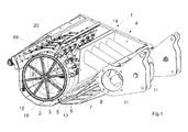
- das Vereinzelungsgehäuse mit der Vereinzelungstrommel und der Vereinzelungsvorrichtung, ohne seitliche Lagerungselemente der Vereinzelungstrommel und ohne Saatgutvorratsbehälter der Einzelkornsämaschine in perspektivischer Ansicht, wobei die vordere Seitenwand abgenommen ist,
- Fig. 2
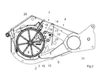
- das Vereinzelungsgehäuse mit der Vereinzelungstrommel gemäß
Fig. 1 in Seitenansicht, - Fig. 3
- die Vereinzelungstrommel mit Rolle der Saatgutablöserolle und dem Anfangsbereich der Ausbringleitung in Seitenansicht,
- Fig. 4
- die Vereinzelungstrommel mit den Rolle der Saatgutablöseeinrictung in perspektivischer Ansicht,
- Fig. 5
- die Vereinzelungstrommel mit Rolle der Saatgutablöserolle und dem Anfangsbereich der Ausbringleitung in Seitenansicht, in Teilansicht und vergrößertem Maßstab und
- Fig. 6
- die Saatgutablöserolle in perspektivischer Ansicht.
- Die Einzelkornsämaschine weist das Vereinzelungsgehäuse 1 mit der darin drehbar gelagerten und angetriebenen Vereinzelungstrommel 2 auf. Über eine nicht dargestellte Antriebsvorrichtung wird die Vereinzelungstrommel 2 in Pfeilrichtung 3 in Rotation versetzt. Oberhalb der Vereinzelungstrommel 2 befindet sich der Bereich mit dem Vorratsbehälter 4. In dem Umfangsmantel 5 der Vereinzelungstrommel 2 sind kreisförmig in Perforationsreihen 6 angeordnete Perforationen 7 angebracht. Der Vorratsbehälter 4 und das Vereinzelungsgehäuse 1 werden auf der Vereinzelungsseite 8 der Trommel 2 mit einem Überdruck beaufschlagt. Somit entsteht eine Druckdifferenz zwischen dem Innenraum 9 der Vereinzelungstrommel 2 und dem Außenbereich 8 der Vereinzelungstrommel 2 in deren Vereinzelungsbereich 10. Die Druckdifferenz wird durch ein nicht dargestelltes Gebläse erzeugt. Das Gebläse ist über den Anschlussstutzen 11 an das Vereinzelungsgehäuse 1 mittels einer Luftleitung angeschlossen. Wenn die Vereinzelungstrommel 2 durch den Saatgutvorrat, der sich im unteren Vorratsbereich 12 des Vereinzelungsgehäuses 1 im unteren Bereich des Vorratsbehälters 4 und zumindest in dem unteren Bereich der Vereinzelungstrommel 2 in dem Vereinzelungsgehäuse 1 befindet, geführt wird, lagern sich an der Perforationen 7 auf der Außenseite 8 der perforierten Trommel 2 Samenkörner 13 an. Die Seitenwände 14 des Vereinzelungsgehäuses 1 erstrecken sich parallel zur Bewegungsrichtung 3 der Trommel 1 und wirken zumindest annähernd abdichtend mit der Trommel 1 zusammen.
- Des weiteren ist der Trommel 2 eine die an die Perforationen 7 anliegenden Druckdifferenz zum Ablösen der Samenkörner 13 von den Perforationen 7 unterbrechende und drehbar gelagerte Rollen 15 aufweisende Saatgutablöseeinrichtung 16 im Innenraum 9 der Trommel 2 zugeordnet. Die Rollen 15 dieser Saatgutablöseeinrichtung 16 sind drehfest auf einer am Vereinzelungsgehäuse 1 drehbar angeordneten Welle 17 gelagert. Die Rollen 15 befinden sich jeweils im bereich der Perforationsreihen 6 zum Abdecken der Perforationen 7.
- Im Vereinzelungsbereich 10 der Trommel 2 ist zwischen dem Saatgutvorratsbereich 12 und dem Bereich, dem die Saatgutablöseeinrichtung 16 zugeordnet ist, eine Abstreifereinrichtung 18 angeordnet, um Doppelbelegungen von Saatkörnern 13 an den Perforationen 7 zu vermeiden.
- Weiterhin weist die Einzelkornsämaschine bis an die Trommeloberfläche der Trommel 2 heranreichende, mit Einmündungsöffnungen 19 versehene Ausbringleitungen 20 auf, welche zu Ausbringelementen, wie beispielsweise Säscharen, führen. Mittels dieser Ausbringleitungen 20 sind die von der Vereinzelungstrommel 2 vereinzelten Saatkörner den Ausbringelementen mittels eines Luftstromes über die Ausbringleitungen 20 zuführbar. Hierbei reicht jeweils das eine Ende der Ausbringleitungen 20 mit ihrer jeweiligen Einmündungsöffnung 19 bis an die Trommeloberfläche der Trommel 2 heran, um so eine sichere Übergabe des vereinzelten Saatkornes über die jeweilige Einmündungsöffnung 19 in die jeweilige Ausbringleitung 20 zu gewährleisten, wie
Fig. 5 zeigt. - Die Rollen 15 der Saatgutablöseeinrichtung 16 weisen einen flexiblen und/oder elastischem Außenring 21 auf. Der elastische und/oder flexible Außenring 21 ist über elastische und/oder flexible speichenartige Zwischenstücke 22 mit einer auf der Welle 17 der drehfest angeordneten Nabe 23 verbunden. Die Rollen 15 können sich um die Längsachse 24 der Welle 17 aufgrund der drehbaren Lagerung der Welle 17 drehen. Die speichenartige Zwischenstücke 21 sind in Drehrichtung 23 der Rolle 15 gekrümmt ausgebildet. Somit ist jede Rolle 15 zumindest in ihrem äußeren Umfangsbereich flexibel und/oder elastisch ausgebildet. Die Breite der Speichen 22 nimmt von innen nach außen zu.
- Zumindest zwischen einigen der Rollen 15 der als Abdeckeinrichtung ausgebildeten Saatgutablöseeinrichtung 16 sind Abstandshalteelemente 25 zur Einhaltung eines bestimmten Abstandes der Drehachse 24 der Welle 17, auf der die Rollen 15 angeordnet sind, zur Innenfläche der Vereinzelungstrommel 2 im Bereich der Perforationsreihen 6 zugeordnet. Somit sind die Rollen 15 und die Abstandshalteelemente 25 auf einer gemeinsamen Welle 17 angeordnet. Die Abstandshalteelemente 25 sind als drehbar gelagerte Ringscheibe ausgebildet. Hierbei sind die Ringscheiben 25 drehfest mit der drehbar gelagerten Welle 17 verbunden.
- Die Rollen 15 weisen einen größeren Durchmesser als die Ringscheiben 25 auf. Die Ringscheiben 25 treiben aufgrund des Reibschlusses zwischen der Innenfläche der Trommel 2 und der Umfangsfläche der Ringscheiben die Rollen 15 der Abdeckeinrichtung 16 an. Hierdurch wird der Schlupf zwischen den Rollen 15 und der Trommel 2 erheblich reduziert. Auf der Lauffläche der Ringscheiben 25 ist ein schmaler Ring 26, beispielsweise ein Gummi- und/oder Kunststoffring angeordnet, um eine bessere Drehkraftübertragung von der Trommel 2 auf die jeweilige Ringscheibe 25 zu gewährleisten.
- Über die Federeinrichtung 27 und der gelenkig mittels des Gelenkes 28 gelagerten Hebelanordnung 29, an welcher die Welle 17, auf welcher die Rollen 15 der Saatgutablöseeinrichtung 16 und die als Ringscheiben 25 ausgebildeten Abstandshalteelemente angeordnet sind, angeordnet ist, werden die Rollen 15 und die Ringscheiben 27 gegen die Innenfläche der Trommel 2 gepresst und/oder gedrückt. Hierbei passen sich die Oberflächen der Rollen 15 aufgrund ihrer flexiblen und/oder elastischem Ausbildung in ihrem äußeren Bereich 21 und der elastischen und oder flexiblen speichenartigen Zwischenstücke 22 sich im Anlagebereich an die Trommel 2 an, wie
Fig. 5 zeigt; die Rolle 15 wird im gegen die Innenfläche der Trommel 2 angepressten Bereich abgeplattet. Dies ist dadurch möglich, dass die Ringscheiben 25 einen kleineren Durchmesser als die Rollen 15 aufweisen. Hierdurch deckt der abgeplattete Bereich der Rolle im Ausführungsbeispiel, wie inFig. 5 dargestellt ist, insgesamt drei hintereinander liegende Perforationen 7 ab.
Claims (8)
- Pneumatische Einzelkornsämaschine mit einem einen Saatgutvorratsbehälter aufweisenden Gehäuse und zumindest einer drehbar angetriebenen Vereinzelungstrommel, in deren Umfangsmantel kreisförmig in Perforationsreihen angeordnete Perforationen angebracht sind, einem Gebläse, mittels welchem eine Druckdifferenz zwischen dem Innenraum der Vereinzelungstrommel und dem Außenbereich der Vereinzelungstrommel erzeugbar ist, so dass, wenn die Vereinzelungstrommel durch den Saatgutvorrat geführt wird, sich an den Perforationen auf der Außenseite der perforierten Trommel Samenkörner anlagern, wobei das Gehäuse zwei voneinander beabstandete Seitenwände aufweist, die sich parallel zur Bewegungsrichtung der Trommel erstrecken und mit der Trommel zumindest annähernd abdichtend zusammenwirken, wobei eine die an die Perforationen angelegte Druckdifferenz zum Ablösen der Saatkörner von den Perforationen unterbrechende als die drehbar gelagerte Rolle ausgebildete Abdeckeinrichtung im Innenraum der Trommel angeordnet ist, wobei im Bereich der Abdeckeinrichtung und den Perforationsreihen jeweils das eine Ende einer Ausbringleitung mit ihrer Einmündungsöffnung bis an die Trommeloberfläche zumindest annähernd heranreichend angeordnet ist, dadurch gekennzeichnet, dass die Rolle (15) zumindest in ihrem äußeren umlaufenden Bereich (21) flexibel und/oder elastisch ausgebildet ist.
- Einzelkornsämaschine nach Anspruch 1, dadurch gekennzeichnet, dass die Rolle (15) aus einem flexiblen und/oder elastischem Außenring (21) besteht, wobei der Außenring (21) über elastische und/oder flexible speichenartige Zwischenstücke (22) mit einer drehbar gelagerten Nabe (23) verbunden ist.
- Einzelkornsämaschine nach zumindest einem der vorstehenden Ansprüche, dadurch gekennzeichnet, dass die speichenartigen Zwischenstücke (22) gekrümmt ausgebildet sind.
- Einzelkornsämaschine nach zumindest einem der vorstehenden Ansprüche, dadurch gekennzeichnet, dass die Krümmung der speichenartigen Zwischenstücke (22) in Drehrichtung der Rollen (15) verläuft.
- Einzelkornsämaschine nach zumindest einem der vorstehenden Ansprüche, dadurch gekennzeichnet, dass die Breite der Speichen (22) von innen nach außen zunimmt.
- Einzelkornsämaschine nach zumindest einem der vorstehenden Ansprüche, dadurch gekennzeichnet, dass den Rollen (15) Abstandshalteelemente (25) zur Einhaltung eines bestimmten Abstandes der Drehachse (24) der Rolle (15) zur Innenfläche der Vereinzelungstrommel (2) im Bereich der Perforationsreihen (6) zugeordnet sind.
- Einzelkornsämaschine nach zumindest einem der vorstehenden Ansprüche, dadurch gekennzeichnet, dass die Rollen (15) und die Abstandshalteelemente (25) auf einer gemeinsamen Achswelle (17) angeordnet sind.
- Einzelkornsämaschine nach zumindest einem der vorstehenden Ansprüche, dadurch gekennzeichnet, dass die Abstandshalteelemente (25) als drehbar gelagerte Ringscheiben ausgebildet sind.
Applications Claiming Priority (1)
| Application Number | Priority Date | Filing Date | Title |
|---|---|---|---|
| DE102011001555A DE102011001555A1 (de) | 2011-03-25 | 2011-03-25 | Pneumatische Einzelkornsämaschine |
Publications (2)
| Publication Number | Publication Date |
|---|---|
| EP2502480A1 true EP2502480A1 (de) | 2012-09-26 |
| EP2502480B1 EP2502480B1 (de) | 2014-04-23 |
Family
ID=46062203
Family Applications (1)
| Application Number | Title | Priority Date | Filing Date |
|---|---|---|---|
| EP12401043.0A Active EP2502480B1 (de) | 2011-03-25 | 2012-03-19 | Pneumatische Einzelkornsämaschine |
Country Status (2)
| Country | Link |
|---|---|
| EP (1) | EP2502480B1 (de) |
| DE (1) | DE102011001555A1 (de) |
Cited By (2)
| Publication number | Priority date | Publication date | Assignee | Title |
|---|---|---|---|---|
| CN105144923A (zh) * | 2015-08-03 | 2015-12-16 | 王玉国 | 小麦选种圃专用单粒播种机 |
| US10149425B2 (en) * | 2013-10-15 | 2018-12-11 | Lemken Gmbh & Co. Kg. | Seed meter for a single-grain seeder |
Families Citing this family (1)
| Publication number | Priority date | Publication date | Assignee | Title |
|---|---|---|---|---|
| CN105103724A (zh) * | 2015-09-09 | 2015-12-02 | 浙江理工大学 | 气力滚筒式异形种子精量排种器 |
Citations (5)
| Publication number | Priority date | Publication date | Assignee | Title |
|---|---|---|---|---|
| FR2491721A1 (fr) * | 1980-10-15 | 1982-04-16 | Dobson George | Semoir |
| US5915312A (en) * | 1997-08-29 | 1999-06-29 | Case Corporation | Pneumatic seed delivery system |
| DE102006016406A1 (de) | 2006-04-07 | 2007-10-11 | Amazonen-Werke H. Dreyer Gmbh & Co. Kg | Pneumatische Einzelkornsämaschine |
| DE102009043881A1 (de) * | 2009-08-27 | 2011-03-03 | Amazonen-Werke H. Dreyer Gmbh & Co. Kg | Pneumatische Einzelkornsämaschine |
| WO2011031214A1 (en) * | 2009-09-14 | 2011-03-17 | xVÄDERSTAD-VERKEN AB | Seed singulator housing and agricultural machine equipped with it |
-
2011
- 2011-03-25 DE DE102011001555A patent/DE102011001555A1/de not_active Withdrawn
-
2012
- 2012-03-19 EP EP12401043.0A patent/EP2502480B1/de active Active
Patent Citations (5)
| Publication number | Priority date | Publication date | Assignee | Title |
|---|---|---|---|---|
| FR2491721A1 (fr) * | 1980-10-15 | 1982-04-16 | Dobson George | Semoir |
| US5915312A (en) * | 1997-08-29 | 1999-06-29 | Case Corporation | Pneumatic seed delivery system |
| DE102006016406A1 (de) | 2006-04-07 | 2007-10-11 | Amazonen-Werke H. Dreyer Gmbh & Co. Kg | Pneumatische Einzelkornsämaschine |
| DE102009043881A1 (de) * | 2009-08-27 | 2011-03-03 | Amazonen-Werke H. Dreyer Gmbh & Co. Kg | Pneumatische Einzelkornsämaschine |
| WO2011031214A1 (en) * | 2009-09-14 | 2011-03-17 | xVÄDERSTAD-VERKEN AB | Seed singulator housing and agricultural machine equipped with it |
Cited By (2)
| Publication number | Priority date | Publication date | Assignee | Title |
|---|---|---|---|---|
| US10149425B2 (en) * | 2013-10-15 | 2018-12-11 | Lemken Gmbh & Co. Kg. | Seed meter for a single-grain seeder |
| CN105144923A (zh) * | 2015-08-03 | 2015-12-16 | 王玉国 | 小麦选种圃专用单粒播种机 |
Also Published As
| Publication number | Publication date |
|---|---|
| DE102011001555A1 (de) | 2012-09-27 |
| EP2502480B1 (de) | 2014-04-23 |
Similar Documents
| Publication | Publication Date | Title |
|---|---|---|
| EP3127414B1 (de) | Dosieraggregat für körniges gut | |
| EP3057402B1 (de) | Säherz für einzelkornsämaschine | |
| EP2923544B1 (de) | Pneumatische einzelkornsämaschine | |
| DE102016203238A1 (de) | Befestigungsanordung einer Duplikatbeseitigungseinheit in einem Saatgutmessgerät | |
| EP2502480B1 (de) | Pneumatische Einzelkornsämaschine | |
| DE102009043881A1 (de) | Pneumatische Einzelkornsämaschine | |
| EP2923543A1 (de) | Pneumatische einzelkornsämaschine | |
| EP3216341B1 (de) | Ballenpresse | |
| DE2312111A1 (de) | Trennvorrichtung fuer kartoffelerntemaschine | |
| EP2974583B9 (de) | Säherz und Einzelkornsämaschine | |
| EP1820382B1 (de) | Pneumatische Einzelkornsämaschine | |
| EP2177098A1 (de) | Vorrichtung zum Vorbereiten des Bodens zum Säen und zum Ausbringen von Saatgut | |
| DE102011002223B3 (de) | Einzelkornausbringeinrichtung | |
| EP3415666B1 (de) | Vorrichtung zur reinigung von fasergut | |
| EP3144420A1 (de) | Reinigungsvorrichtung für eine verdichtungsvorrichtung | |
| EP2559330A1 (de) | Pneumatische Einzelkornsämaschine | |
| EP2361492B1 (de) | Pneumatische Einzelkornsämaschine | |
| DE102016122552A1 (de) | Landwirtschaftliche Verteilmaschine mit Rühreinrichtung | |
| DE102006012539A1 (de) | Pneumatische Einzelkornsämaschine | |
| EP2510769A1 (de) | Pneumatische Einzelkornsämaschine | |
| DE2815048A1 (de) | Maschine zur gewinnung von heu und zur bildung von schwaden | |
| EP2564681B1 (de) | Pneumatische Einzelkornsämaschine | |
| DE341888C (de) | Verfahren und Vorrichtung zum Auseinandernehmen gebuendelter Tabakblaetter | |
| EP1704763A1 (de) | Vorrichtung zum Abstreifen von überschüssigen Samenkörnern | |
| DE483125C (de) | Vorrichtung zum Trennen der Kerne und Schalen geknackter Nuesse voneinander |
Legal Events
| Date | Code | Title | Description |
|---|---|---|---|
| PUAI | Public reference made under article 153(3) epc to a published international application that has entered the european phase |
Free format text: ORIGINAL CODE: 0009012 |
|
| AK | Designated contracting states |
Kind code of ref document: A1 Designated state(s): AL AT BE BG CH CY CZ DE DK EE ES FI FR GB GR HR HU IE IS IT LI LT LU LV MC MK MT NL NO PL PT RO RS SE SI SK SM TR |
|
| AX | Request for extension of the european patent |
Extension state: BA ME |
|
| 17P | Request for examination filed |
Effective date: 20130112 |
|
| GRAP | Despatch of communication of intention to grant a patent |
Free format text: ORIGINAL CODE: EPIDOSNIGR1 |
|
| RIC1 | Information provided on ipc code assigned before grant |
Ipc: A01C 7/04 20060101AFI20131129BHEP |
|
| INTG | Intention to grant announced |
Effective date: 20140107 |
|
| GRAS | Grant fee paid |
Free format text: ORIGINAL CODE: EPIDOSNIGR3 |
|
| GRAA | (expected) grant |
Free format text: ORIGINAL CODE: 0009210 |
|
| AK | Designated contracting states |
Kind code of ref document: B1 Designated state(s): AL AT BE BG CH CY CZ DE DK EE ES FI FR GB GR HR HU IE IS IT LI LT LU LV MC MK MT NL NO PL PT RO RS SE SI SK SM TR |
|
| REG | Reference to a national code |
Ref country code: GB Ref legal event code: FG4D Free format text: NOT ENGLISH |
|
| REG | Reference to a national code |
Ref country code: CH Ref legal event code: EP |
|
| REG | Reference to a national code |
Ref country code: AT Ref legal event code: REF Ref document number: 663201 Country of ref document: AT Kind code of ref document: T Effective date: 20140515 |
|
| REG | Reference to a national code |
Ref country code: IE Ref legal event code: FG4D Free format text: LANGUAGE OF EP DOCUMENT: GERMAN |
|
| REG | Reference to a national code |
Ref country code: DE Ref legal event code: R096 Ref document number: 502012000622 Country of ref document: DE Effective date: 20140612 |
|
| REG | Reference to a national code |
Ref country code: SE Ref legal event code: TRGR |
|
| REG | Reference to a national code |
Ref country code: NL Ref legal event code: VDEP Effective date: 20140423 |
|
| REG | Reference to a national code |
Ref country code: LT Ref legal event code: MG4D |
|
| PG25 | Lapsed in a contracting state [announced via postgrant information from national office to epo] |
Ref country code: LT Free format text: LAPSE BECAUSE OF FAILURE TO SUBMIT A TRANSLATION OF THE DESCRIPTION OR TO PAY THE FEE WITHIN THE PRESCRIBED TIME-LIMIT Effective date: 20140423 Ref country code: FI Free format text: LAPSE BECAUSE OF FAILURE TO SUBMIT A TRANSLATION OF THE DESCRIPTION OR TO PAY THE FEE WITHIN THE PRESCRIBED TIME-LIMIT Effective date: 20140423 Ref country code: GR Free format text: LAPSE BECAUSE OF FAILURE TO SUBMIT A TRANSLATION OF THE DESCRIPTION OR TO PAY THE FEE WITHIN THE PRESCRIBED TIME-LIMIT Effective date: 20140724 Ref country code: CY Free format text: LAPSE BECAUSE OF FAILURE TO SUBMIT A TRANSLATION OF THE DESCRIPTION OR TO PAY THE FEE WITHIN THE PRESCRIBED TIME-LIMIT Effective date: 20140423 Ref country code: BG Free format text: LAPSE BECAUSE OF FAILURE TO SUBMIT A TRANSLATION OF THE DESCRIPTION OR TO PAY THE FEE WITHIN THE PRESCRIBED TIME-LIMIT Effective date: 20140723 Ref country code: NL Free format text: LAPSE BECAUSE OF FAILURE TO SUBMIT A TRANSLATION OF THE DESCRIPTION OR TO PAY THE FEE WITHIN THE PRESCRIBED TIME-LIMIT Effective date: 20140423 Ref country code: NO Free format text: LAPSE BECAUSE OF FAILURE TO SUBMIT A TRANSLATION OF THE DESCRIPTION OR TO PAY THE FEE WITHIN THE PRESCRIBED TIME-LIMIT Effective date: 20140723 Ref country code: IS Free format text: LAPSE BECAUSE OF FAILURE TO SUBMIT A TRANSLATION OF THE DESCRIPTION OR TO PAY THE FEE WITHIN THE PRESCRIBED TIME-LIMIT Effective date: 20140823 |
|
| PG25 | Lapsed in a contracting state [announced via postgrant information from national office to epo] |
Ref country code: LV Free format text: LAPSE BECAUSE OF FAILURE TO SUBMIT A TRANSLATION OF THE DESCRIPTION OR TO PAY THE FEE WITHIN THE PRESCRIBED TIME-LIMIT Effective date: 20140423 Ref country code: RS Free format text: LAPSE BECAUSE OF FAILURE TO SUBMIT A TRANSLATION OF THE DESCRIPTION OR TO PAY THE FEE WITHIN THE PRESCRIBED TIME-LIMIT Effective date: 20140423 Ref country code: HR Free format text: LAPSE BECAUSE OF FAILURE TO SUBMIT A TRANSLATION OF THE DESCRIPTION OR TO PAY THE FEE WITHIN THE PRESCRIBED TIME-LIMIT Effective date: 20140423 Ref country code: ES Free format text: LAPSE BECAUSE OF FAILURE TO SUBMIT A TRANSLATION OF THE DESCRIPTION OR TO PAY THE FEE WITHIN THE PRESCRIBED TIME-LIMIT Effective date: 20140423 Ref country code: PL Free format text: LAPSE BECAUSE OF FAILURE TO SUBMIT A TRANSLATION OF THE DESCRIPTION OR TO PAY THE FEE WITHIN THE PRESCRIBED TIME-LIMIT Effective date: 20140423 |
|
| PG25 | Lapsed in a contracting state [announced via postgrant information from national office to epo] |
Ref country code: PT Free format text: LAPSE BECAUSE OF FAILURE TO SUBMIT A TRANSLATION OF THE DESCRIPTION OR TO PAY THE FEE WITHIN THE PRESCRIBED TIME-LIMIT Effective date: 20140825 |
|
| REG | Reference to a national code |
Ref country code: DE Ref legal event code: R097 Ref document number: 502012000622 Country of ref document: DE |
|
| PG25 | Lapsed in a contracting state [announced via postgrant information from national office to epo] |
Ref country code: EE Free format text: LAPSE BECAUSE OF FAILURE TO SUBMIT A TRANSLATION OF THE DESCRIPTION OR TO PAY THE FEE WITHIN THE PRESCRIBED TIME-LIMIT Effective date: 20140423 Ref country code: DK Free format text: LAPSE BECAUSE OF FAILURE TO SUBMIT A TRANSLATION OF THE DESCRIPTION OR TO PAY THE FEE WITHIN THE PRESCRIBED TIME-LIMIT Effective date: 20140423 Ref country code: CZ Free format text: LAPSE BECAUSE OF FAILURE TO SUBMIT A TRANSLATION OF THE DESCRIPTION OR TO PAY THE FEE WITHIN THE PRESCRIBED TIME-LIMIT Effective date: 20140423 Ref country code: SK Free format text: LAPSE BECAUSE OF FAILURE TO SUBMIT A TRANSLATION OF THE DESCRIPTION OR TO PAY THE FEE WITHIN THE PRESCRIBED TIME-LIMIT Effective date: 20140423 Ref country code: RO Free format text: LAPSE BECAUSE OF FAILURE TO SUBMIT A TRANSLATION OF THE DESCRIPTION OR TO PAY THE FEE WITHIN THE PRESCRIBED TIME-LIMIT Effective date: 20140423 |
|
| PLBE | No opposition filed within time limit |
Free format text: ORIGINAL CODE: 0009261 |
|
| STAA | Information on the status of an ep patent application or granted ep patent |
Free format text: STATUS: NO OPPOSITION FILED WITHIN TIME LIMIT |
|
| 26N | No opposition filed |
Effective date: 20150126 |
|
| REG | Reference to a national code |
Ref country code: DE Ref legal event code: R097 Ref document number: 502012000622 Country of ref document: DE Effective date: 20150126 |
|
| PG25 | Lapsed in a contracting state [announced via postgrant information from national office to epo] |
Ref country code: SI Free format text: LAPSE BECAUSE OF FAILURE TO SUBMIT A TRANSLATION OF THE DESCRIPTION OR TO PAY THE FEE WITHIN THE PRESCRIBED TIME-LIMIT Effective date: 20140423 |
|
| PG25 | Lapsed in a contracting state [announced via postgrant information from national office to epo] |
Ref country code: LU Free format text: LAPSE BECAUSE OF FAILURE TO SUBMIT A TRANSLATION OF THE DESCRIPTION OR TO PAY THE FEE WITHIN THE PRESCRIBED TIME-LIMIT Effective date: 20150319 Ref country code: MC Free format text: LAPSE BECAUSE OF FAILURE TO SUBMIT A TRANSLATION OF THE DESCRIPTION OR TO PAY THE FEE WITHIN THE PRESCRIBED TIME-LIMIT Effective date: 20140423 |
|
| REG | Reference to a national code |
Ref country code: CH Ref legal event code: PL |
|
| REG | Reference to a national code |
Ref country code: IE Ref legal event code: MM4A |
|
| PG25 | Lapsed in a contracting state [announced via postgrant information from national office to epo] |
Ref country code: CH Free format text: LAPSE BECAUSE OF NON-PAYMENT OF DUE FEES Effective date: 20150331 Ref country code: IE Free format text: LAPSE BECAUSE OF NON-PAYMENT OF DUE FEES Effective date: 20150319 Ref country code: LI Free format text: LAPSE BECAUSE OF NON-PAYMENT OF DUE FEES Effective date: 20150331 |
|
| REG | Reference to a national code |
Ref country code: FR Ref legal event code: PLFP Year of fee payment: 5 |
|
| GBPC | Gb: european patent ceased through non-payment of renewal fee |
Effective date: 20160319 |
|
| PG25 | Lapsed in a contracting state [announced via postgrant information from national office to epo] |
Ref country code: MT Free format text: LAPSE BECAUSE OF FAILURE TO SUBMIT A TRANSLATION OF THE DESCRIPTION OR TO PAY THE FEE WITHIN THE PRESCRIBED TIME-LIMIT Effective date: 20140423 |
|
| PG25 | Lapsed in a contracting state [announced via postgrant information from national office to epo] |
Ref country code: GB Free format text: LAPSE BECAUSE OF NON-PAYMENT OF DUE FEES Effective date: 20160319 |
|
| REG | Reference to a national code |
Ref country code: FR Ref legal event code: PLFP Year of fee payment: 6 |
|
| PG25 | Lapsed in a contracting state [announced via postgrant information from national office to epo] |
Ref country code: HU Free format text: LAPSE BECAUSE OF FAILURE TO SUBMIT A TRANSLATION OF THE DESCRIPTION OR TO PAY THE FEE WITHIN THE PRESCRIBED TIME-LIMIT; INVALID AB INITIO Effective date: 20120319 Ref country code: SM Free format text: LAPSE BECAUSE OF FAILURE TO SUBMIT A TRANSLATION OF THE DESCRIPTION OR TO PAY THE FEE WITHIN THE PRESCRIBED TIME-LIMIT Effective date: 20140423 |
|
| PG25 | Lapsed in a contracting state [announced via postgrant information from national office to epo] |
Ref country code: BE Free format text: LAPSE BECAUSE OF NON-PAYMENT OF DUE FEES Effective date: 20150331 |
|
| PG25 | Lapsed in a contracting state [announced via postgrant information from national office to epo] |
Ref country code: TR Free format text: LAPSE BECAUSE OF FAILURE TO SUBMIT A TRANSLATION OF THE DESCRIPTION OR TO PAY THE FEE WITHIN THE PRESCRIBED TIME-LIMIT Effective date: 20140423 |
|
| REG | Reference to a national code |
Ref country code: FR Ref legal event code: PLFP Year of fee payment: 7 |
|
| REG | Reference to a national code |
Ref country code: AT Ref legal event code: MM01 Ref document number: 663201 Country of ref document: AT Kind code of ref document: T Effective date: 20170319 |
|
| PG25 | Lapsed in a contracting state [announced via postgrant information from national office to epo] |
Ref country code: MK Free format text: LAPSE BECAUSE OF FAILURE TO SUBMIT A TRANSLATION OF THE DESCRIPTION OR TO PAY THE FEE WITHIN THE PRESCRIBED TIME-LIMIT Effective date: 20140423 |
|
| PG25 | Lapsed in a contracting state [announced via postgrant information from national office to epo] |
Ref country code: AT Free format text: LAPSE BECAUSE OF NON-PAYMENT OF DUE FEES Effective date: 20170319 |
|
| PG25 | Lapsed in a contracting state [announced via postgrant information from national office to epo] |
Ref country code: AL Free format text: LAPSE BECAUSE OF FAILURE TO SUBMIT A TRANSLATION OF THE DESCRIPTION OR TO PAY THE FEE WITHIN THE PRESCRIBED TIME-LIMIT Effective date: 20140423 |
|
| PGFP | Annual fee paid to national office [announced via postgrant information from national office to epo] |
Ref country code: FR Payment date: 20210210 Year of fee payment: 10 |
|
| REG | Reference to a national code |
Ref country code: DE Ref legal event code: R082 Ref document number: 502012000622 Country of ref document: DE Representative=s name: KILBURN & STRODE LLP, GB Ref country code: DE Ref legal event code: R082 Ref document number: 502012000622 Country of ref document: DE Representative=s name: KILBURN & STRODE LLP, NL Ref country code: DE Ref legal event code: R081 Ref document number: 502012000622 Country of ref document: DE Owner name: AMAZONEN-WERKE H. DREYER SE & CO. KG, DE Free format text: FORMER OWNER: AMAZONEN-WERKE H. DREYER GMBH & CO. KG, 49205 HASBERGEN, DE |
|
| REG | Reference to a national code |
Ref country code: DE Ref legal event code: R082 Ref document number: 502012000622 Country of ref document: DE Representative=s name: KILBURN & STRODE LLP, NL |
|
| PG25 | Lapsed in a contracting state [announced via postgrant information from national office to epo] |
Ref country code: FR Free format text: LAPSE BECAUSE OF NON-PAYMENT OF DUE FEES Effective date: 20220331 |
|
| P01 | Opt-out of the competence of the unified patent court (upc) registered |
Effective date: 20230523 |
|
| PGFP | Annual fee paid to national office [announced via postgrant information from national office to epo] |
Ref country code: SE Payment date: 20260105 Year of fee payment: 15 |
|
| PGFP | Annual fee paid to national office [announced via postgrant information from national office to epo] |
Ref country code: DE Payment date: 20260102 Year of fee payment: 15 |
|
| PGFP | Annual fee paid to national office [announced via postgrant information from national office to epo] |
Ref country code: IT Payment date: 20260220 Year of fee payment: 15 |