EP2501876B1 - Aus einem satz montagefertiger separater teile geformtes geländer - Google Patents
Aus einem satz montagefertiger separater teile geformtes geländer Download PDFInfo
- Publication number
- EP2501876B1 EP2501876B1 EP10795433.1A EP10795433A EP2501876B1 EP 2501876 B1 EP2501876 B1 EP 2501876B1 EP 10795433 A EP10795433 A EP 10795433A EP 2501876 B1 EP2501876 B1 EP 2501876B1
- Authority
- EP
- European Patent Office
- Prior art keywords
- intended
- transverse element
- uprights
- transverse
- railing
- Prior art date
- Legal status (The legal status is an assumption and is not a legal conclusion. Google has not performed a legal analysis and makes no representation as to the accuracy of the status listed.)
- Active
Links
- 238000005553 drilling Methods 0.000 claims description 13
- 230000000295 complement effect Effects 0.000 claims description 7
- 239000011521 glass Substances 0.000 claims description 5
- 238000007747 plating Methods 0.000 claims description 4
- 208000031968 Cadaver Diseases 0.000 description 23
- BASFCYQUMIYNBI-UHFFFAOYSA-N platinum Chemical compound [Pt] BASFCYQUMIYNBI-UHFFFAOYSA-N 0.000 description 8
- 239000000463 material Substances 0.000 description 7
- 229910052751 metal Inorganic materials 0.000 description 7
- 239000002184 metal Substances 0.000 description 7
- 238000004026 adhesive bonding Methods 0.000 description 5
- 239000002131 composite material Substances 0.000 description 5
- 238000005520 cutting process Methods 0.000 description 5
- 238000003754 machining Methods 0.000 description 5
- 238000004519 manufacturing process Methods 0.000 description 5
- 238000003466 welding Methods 0.000 description 5
- 229910052782 aluminium Inorganic materials 0.000 description 4
- XAGFODPZIPBFFR-UHFFFAOYSA-N aluminium Chemical compound [Al] XAGFODPZIPBFFR-UHFFFAOYSA-N 0.000 description 4
- 238000000465 moulding Methods 0.000 description 4
- 238000005096 rolling process Methods 0.000 description 4
- 239000002023 wood Substances 0.000 description 4
- 229910000838 Al alloy Inorganic materials 0.000 description 3
- 229910052697 platinum Inorganic materials 0.000 description 3
- 229920001059 synthetic polymer Polymers 0.000 description 3
- 230000007547 defect Effects 0.000 description 2
- 239000006260 foam Substances 0.000 description 2
- 238000004080 punching Methods 0.000 description 2
- 238000010079 rubber tapping Methods 0.000 description 2
- 239000004925 Acrylic resin Substances 0.000 description 1
- 229920000178 Acrylic resin Polymers 0.000 description 1
- 239000011324 bead Substances 0.000 description 1
- 238000009954 braiding Methods 0.000 description 1
- 238000001125 extrusion Methods 0.000 description 1
- 238000003780 insertion Methods 0.000 description 1
- 230000037431 insertion Effects 0.000 description 1
- 239000003562 lightweight material Substances 0.000 description 1
- 238000012423 maintenance Methods 0.000 description 1
- 238000000034 method Methods 0.000 description 1
- 238000003801 milling Methods 0.000 description 1
- 229920001296 polysiloxane Polymers 0.000 description 1
- 239000007787 solid Substances 0.000 description 1
- XLYOFNOQVPJJNP-UHFFFAOYSA-N water Substances O XLYOFNOQVPJJNP-UHFFFAOYSA-N 0.000 description 1
Images


Classifications
-
- E—FIXED CONSTRUCTIONS
- E04—BUILDING
- E04F—FINISHING WORK ON BUILDINGS, e.g. STAIRS, FLOORS
- E04F11/00—Stairways, ramps, or like structures; Balustrades; Handrails
- E04F11/18—Balustrades; Handrails
- E04F11/181—Balustrades
- E04F11/1812—Details of anchoring to the wall or floor
-
- E—FIXED CONSTRUCTIONS
- E04—BUILDING
- E04F—FINISHING WORK ON BUILDINGS, e.g. STAIRS, FLOORS
- E04F11/00—Stairways, ramps, or like structures; Balustrades; Handrails
- E04F11/18—Balustrades; Handrails
- E04F11/181—Balustrades
- E04F11/1817—Connections therefor
-
- E—FIXED CONSTRUCTIONS
- E04—BUILDING
- E04F—FINISHING WORK ON BUILDINGS, e.g. STAIRS, FLOORS
- E04F11/00—Stairways, ramps, or like structures; Balustrades; Handrails
- E04F11/18—Balustrades; Handrails
- E04F11/181—Balustrades
- E04F11/1817—Connections therefor
- E04F2011/1819—Connections therefor between balustrade posts and horizontal or sloping balustrade members
- E04F2011/1821—Connections therefor between balustrade posts and horizontal or sloping balustrade members between balustrade posts and handrails
Definitions
- the subject of the invention is a railing consisting of a set of spare parts ready to be assembled.
- Railings consist of a set of spare parts ready to be assembled. These railings are generally formed by the assembly of uprights and sleepers formed by aluminum profiles. See for example DE 20 2005 006 574 U1 .
- the profiles used have profiles whose complex shape is difficult and expensive to manufacture.
- the assembly time of these railings is particularly long, firstly due to a large number of parts to be assembled, and secondly due to a problem of identification and distinction among the profiles of those forming the sleepers and those forming the uprights, the set of profiles having, for aesthetic reasons, similar shapes that can be easily confused.
- the main purpose of the invention is to provide a light railing consisting of a minimum of spare parts quickly. identifiable, said parts can be easily and quickly mounted and taking up a minimum of space during transport.
- Another object of the invention is to provide a guard rail of simple and inexpensive design.
- the solution proposed by the invention is a railing consisting of a reduced set of spare parts ready to be assembled, as in claim 1.
- Such a railing has few parts assembling easily and quickly by interlocking.
- the amounts formed of a flat blade are easily identifiable among the other parts, which can significantly reduce the assembly time.
- the temporary fixing means is advantageously in the form of a set screw intended to be screwed into a threaded hole made on the portion of the uprights, said tapped hole opening into the bore, the end of said needle screw being intended to exert a contact force directly on the transverse element so as to constrain the latter against the inner wall of the bore and ensure its maintenance in position on said amount.
- the needle screw makes it easy and quick to hold the transverse element in position on the uprights, said needle screw cooperating with a threaded hole made on the upright resulting from a simple, fast and inexpensive machining.
- the plate is made of glass, joints being intended to be arranged between the plate and the upper transverse element and / or the lower transverse element so as to call said plate between said transverse elements.
- the glass plate is thus clamped between the transverse elements by means of joints so that it does not break.
- the latter advantageously have a slot in which is intended to engage the lower part of the amounts.
- said plates preferably have oblong holes for the passage of fixing means for the plating of said plates on the ground, said plates being movable relative to said fixing means via the oblong holes, in a sliding motion on the floor.
- said plates may have at least one threaded hole in which a set screw is intended to be screwed, the end of said set screw being intended to exert a contact force against the ground so as to oppose the sliding of said plate on said floor and to compensate for possible planimetry defects of the generally masonry ground.
- the guardrail can include as spare parts several transverse elements intended to be positioned transversally to the uprights at different heights, each transverse element being intended to be inserted in bores. made on said uprights, said transverse elements and said holes having a complementary shape.
- the transverse element intended to be arranged highest on the uprights is preferably a tube having a diameter of at least 50 mm and a thickness of at least 2 mm.
- the transverse element thus formed has sufficient strength to meet the safety standards in force.
- transverse element or elements intended to be arranged below the uppermost transverse element are advantageously tubes having a diameter at least equal to 20 mm and a thickness of at least 1.5 mm.
- the lower transverse elements then have sufficient strength to meet the safety standards in force.
- guardrail (1) consisting of a set of spare parts, in small quantities, ready to be assembled. Two non-limiting embodiments of this railing (1) are described respectively in the following point 1 and 2.
- the guardrail (1) comprises at least two uprights (2) at each of its ends, one or more other uprights (2) can be interposed between. These amounts (2) may or may not be spaced regularly.
- the railing (1) has an amount (2) every 150 cm, but may also include an amount (2) every 80 cm, every 100 cm, every 180 cm, every 190 cm, etc.
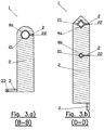
- an upright (2) consists of a vertical flat blade.
- the term "blade” means a flat elongated strip longer than wide, and possibly wider than thick.
- the uprights (2) are made of a hard material such as metal, wood, composite material, etc.
- the uprights (2) are made of light material of the aluminum or aluminum alloy type. They can be obtained by machining, molding, rolling, cutting, etc.
- the uprights (2) may have a thickness ranging from 1 cm to 3 cm, a width ranging from 5 cm to 10 cm and a length ranging from 20 cm to 120 cm. The corners and edges of the blade can be chamfered or rounded.
- the uprights (2) comprise at least one bore (21) capable of allowing the insertion of a transverse element (4a, 4b) described in more detail in paragraph 1.3 of the description.
- the uprights (2) may comprise several bores (21) evenly spaced or not along their length. In practice, two holes (21) are spaced apart by a distance of less than or equal to 18 cm.
- the bore (21) is arranged on one of the faces of the blade forming the upright (2) and opens on the other side.
- the bore (21) can have a circular profile as shown on the Figures 3.a) to 6.c) but may also have an oval, square, triangular, diamond-shaped, square-shaped, arc-shaped, or any other profile suitable for those skilled in the art.
- the profile of the piercing (21) may have a diameter or a side varying from 2 cm to 8 cm.
- the holes (21) can be obtained by machining, drilling, boring, punching, etc.
- the uprights (2) may also include a housing (22) on their wafer for receiving a temporary fixing means (5) described in more detail in point 1.4 of the description.
- this housing (22) is in the form of a tapped hole or not, made on the edge of the uprights (2) and opening into the bore (21) described above. It is usually obtained by drilling and possibly tapping.
- This housing (22) can have a diameter ranging from 0.3 cm to 1.5 cm.
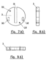
- each upright (2) is intended to be fixed on a plate (3).
- the plates (3) are in the form of a circular plate, square, rectangular, oval, or other. They are made of metal, wood, composite materials, etc.
- the plates (3) are made of light material of the aluminum or aluminum alloy type. They can be obtained by machining, molding, rolling, cutting, etc.
- the plates (3) can have a thickness ranging from 0.5 cm to 3 cm, a length and a width or a diameter ranging from 10 cm to 30 cm.
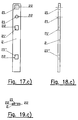
- the plates (3) schematically represented on the figures 7.a) to 9.b) have a slot (31) in which is intended to engage the lower portion of the uprights (2).
- This slot (31) has a rectangular shape complementary to the lower edge of the uprights (2) and as such can have a width ranging from 1 cm to 3 cm and a length ranging from 5 cm to 10 cm.
- the bearing surface of the plates (3) can be either horizontal ( figures 1.a), 1.c) and 1.d) ) so that they can be fixed against the ground, Figure 1.b) ), so that they can be fixed against a wall or against the edge of a balcony or terrace.
- the uprights (2) are generally fixed on these plates (3) by arc welding, torch welding, or MIG-TIG welding, but can also be fixed by forced assembly, gluing, riveting, screwing, etc.
- the plates (3) may also have oblong holes (32) for the passage of fixing means for the plating of said plates on the ground.
- the oblong holes (32) are in practice two in number, are arranged on one side of the plate (3) and open on the other side, and are arranged on either side of the slot (31). ) as schematized on the figures 7.a) and 7.b) , but they can also be more numerous and regularly distributed or not on the periphery of the platinum. They can have a rectangular, oval or other shape, and can be obtained by machining, cutting, milling, molding, etc.
- the fastening means for plating the plates (3) on the ground can be in the form of screws, studs and nuts, and washers, rivets, or any other means of attachment suitable for the man of art.
- the plates (3) may also have one or more tapped holes (33) in which a needle screw is intended to be screwed.
- the tapped holes (33) are arranged on one of the faces of the plate (3) and open on the other side and are generally obtained by drilling and tapping. They may or may not be arranged regularly on the periphery of the plates (3). They can have a diameter ranging from 0.3 cm to 1.5 cm.
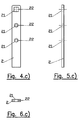
- At least one transverse element (4a, 4b) is intended to be positioned transversely to the uprights (2).
- the transverse elements (4a, 4b) are generally positioned at different heights. They can be distributed regularly or not on the height of amounts (2). In practice, two transverse elements (4a, 4b) are spaced apart by a distance of less than or equal to 18 cm.
- the transverse elements (4a, 4b) are in the form of profiles having an oval, square, triangular, diamond-shaped, square, arcuate, or any other section suitable for man art.
- the transverse elements (4a, 4b) being intended to be inserted into the bores (21) of the uprights (2) described above in point 1.1, said transverse elements and said bores preferably have a complementary shape. They can be made of metal, wood, composite material, etc.
- the transverse elements (4a, 4b) are made of lightweight material of the aluminum or aluminum alloy type. They can be obtained by profiling, extrusion, molding, rolling, folding, cutting, etc.
- the transverse elements (4a, 4b) may have a length less than or equal to 600 cm, a width and a height or a diameter ranging from 2 cm to 8 cm, and a profile thickness ranging from 1 mm to 6 mm.
- the transverse element (4a) intended to be arranged highest on the uprights (2) is a tube of diameter at least equal to 50 mm and of thickness at least equal to 2 mm, so as to meet the standards. of security in force.
- the transverse element or elements (4b) disposed below this transverse element (4a) are preferably tubes with a diameter of at least 20 mm and a thickness of at least 1.5 mm, so as to meet the safety standards in force.
- the railing (1) comprises for each transverse element (4a, 4b), at least one temporary fixing means (5).
- the latter can be in the form of a screw, a pin, a rivet, or other. It may have a diameter of at least 0.2 cm and a length of at least 0.5 cm.
- the fixing means (5) is generally arranged on the edge of each upright (2), preferably in a housing (22) such as that described previously in point 1.1.
- the fixing means (5) is intended to apply a contact force directly on the transverse element (4a, 4b) so as to constrain the latter against the inner wall of the bore (21) and to hold said transverse element in position on the amount (2). This contact force can be applied to the inner or outer surface of the transverse element (4a, 4b).
- the temporary fixing means (5) is in the form of a needle screw intended to be screwed into a housing (22) in the form of a threaded hole, made on the edge. amounts (2) and opening into the bore (21).
- the needle screw Once the needle screw is put in place in the tapped hole, its end exerts the contact force directly on the transverse element (4a, 4b). Its end can also locally deform the transverse element (4a, 4b) and / or sink into it, so as to oppose by obstacle the disinsertion of said transverse element of the upright (2).
- a lower transverse element (4 ") is positioned transversely to the uprights (2)
- the lower transverse element (4") is arranged in the lower part of the railing (1) at a distance from the ground varying from 1 cm to 11 cm according to the standards in force.
- the lower transverse element (4 ") is in the form of a profile having a horizontal bearing surface (41") for supporting the plate (6) (hereinafter described in 2.3) and a surface vertical support (42 ") for guiding said plate along said horizontal bearing surface, whereby the lower transverse element (4") may have an L, U, V, H, X, or any other section suitable for those skilled in the art.
- the lower transverse element (4 ") is intended to be inserted into lower bores (21") made on the uprights (2).
- These lower bores (21 ") are of the same type as the bores (21) described previously in point 1.1
- the lower transverse element (4") and the lower bores (21 ") preferably have a complementary shape.
- lower (4 ") can be made in similar materials, by similar production processes and in similar dimensions to the transverse elements (4a, 4b) described previously in point 1.3 of the description.
- the lower transverse element (4 ") is intended to be inserted into lower support parts (45") in the form of U-shaped profiles approximately 3 cm in length.
- These lower support pieces (45 ") are fixed on the uprights (2) by welding, gluing, screwing, etc.
- bores (21") are made in the lower part of the uprights (2) and in which are screwed the lower support parts (45 ") via a male / female screw system
- a needle screw (46") advantageously allows the lower transverse element (4 ") to be immobilized in the lower support parts (45").
- the latter may also include a rib bearing against the upright (2) so as to stiffen the assembly.
- an upper transverse element (4 ') is also positioned transversely to the uprights (2).
- the upper transverse element (4 ') is arranged above the lower transverse element (4 ")
- a distance varying from 20 cm to 100 cm can separate the upper transversal elements (4') and the lower transverse elements (4 ').
- a distance ranging from 0 mm to 180 mm may also separate the upper transverse element (4 ') from the transverse element (4a, 4b) located directly above.
- the upper transverse element (4 ') is in the form of a profile having a vertical bearing surface (42') for holding the plate (6) in a vertical position.
- the transverse element (4 ') may have a T-shaped section, I, L coated, U or inverted V, or any other section suitable for those skilled in the art.
- the upper transverse element (4 ') is intended to be inserted in upper bores (21') made on the uprights (2). These upper bores (21 ') are of the same type as the bores (21) described previously in point 1.1.
- the upper transverse element (4 ') and the bores (21') preferably have a complementary shape.
- the upper transverse element (4 ') can be made of similar materials, by similar production processes and in similar dimensions to the transverse elements (4a, 4b) described previously in point 1.3 of the description.
- the upper transverse element (4 ') is intended to bear on upper support parts (45') in the form of U-shaped profiles inverted about 3 cm in length.
- the upper transverse element (4 ') comes to cap the upper support parts (45 ').
- These are fixed on the uprights (2) by welding, gluing, screwing, etc.
- bores (21 ') are provided in the upper part of the uprights (2) and in which the upper support parts (45') are screwed by means of a male / female screw system.
- a needle screw may possibly come to immobilize the upper transverse element (4 ') in the upper support parts (45').
- attachment means (5) of the upper transversal elements (4 ') and lower (4 ") are similar to those described above in point 1.4 of the description.
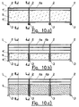
- a plate (6) is inserted between the upper transverse element (4 ') and the lower transverse element (4 ")
- the lower edge of the plate (6) guided by the vertical bearing surface (42 ") of the lower transverse element (4"), bears against the horizontal bearing surface (41 ") of said lower transverse element (4"), the upper part of the plate (6) then rests against the vertical bearing surface (42 ') of the upper transverse element (4'), in this way the plate (6) is held in a vertical position between the upper (4 ') and the lower (4 ") transverse elements ).
- Several plates (6) can be arranged side by side.
- the plate (6) can be solid, perforated, braided or cut with a pattern by laser or water jet and obtained by rolling, cutting, punching, braiding slats or rods, etc. It has in practice a length that can vary from 20 cm to 150 cm, a height that can vary from 20 cm to 100 cm, and a thickness that can vary from 0.2 cm to 2 cm. She may be made of glass, acrylic resin, metal, wood, composite material, etc.
- seals (8) can be arranged between said plate and the upper transversal element (4 ') and / or lower (4 ") so as to the caller between said transverse elements.
- the seals (8) are silicone seals applied on the one hand against the vertical bearing surfaces (42 ', 42 ") of the upper (4') or lower (4") transverse members, and on the other hand between the plate (6) and said transverse elements.
- the seals (8) may, however, be made of foam, rubber or soft synthetic polymer, or the like, and be fixed against the vertical bearing surfaces (42 ', 42 ") by gluing.
- a damper (9) of foam, rubber, flexible synthetic polymer or the like may be arranged against the horizontal bearing surface (41 ') of the lower transverse member (4 ") between the plate (6) ) and said transverse element.
- a single gasket (89) having a U-shaped section is used.
- This gasket (89) is generally made of rubber or flexible synthetic polymer. It is inserted in the upper transversal element (4 ') and / or lower (4 "), the latter also having a U-shaped section.
- the seal (89) has on its inner and / or outer edges a series of lips for resiliently engaging the plate (6) within the cross members (4 ') and / or (4 ").
- the guardrail (1) can comprise an obstacle (7) opposing the disinsertion of the plate (6) from between the two transverse elements (4 ', 4 ").
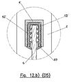
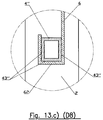
- This obstacle (7) can present itself in the form of a rod, a bead, a section, or other ( figures 12.a) and 13.a) ).
- the obstacle (7) may also consist of a part of the profile forming the upper (4 ') or lower (4 ") transverse element ( figures 12.b) and 13.b) ). It can be made of metal, composite material, etc.
- the obstacle (7) may have a width and a height varying from 1.3 cm to 8 cm and a length ranging from 2 cm to 200 cm.
- One or more obstacles (7) can be fixed on the upper transversal element (4 ') and / or lower (4 ") so as to oppose the disinsertion of the plate (6) from between said two elements
- the obstacle (7) can be removably or non-detachably secured by screwing, riveting, gluing, or otherwise
- the obstacle (7) has a vertical bearing surface (72) for gripping the plate (6) against the vertical bearing surface (42 ', 42 ") of the upper (4') and / or lower (4") transverse element.
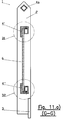
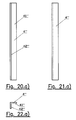
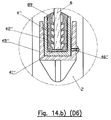
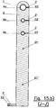
- the guardrail (1) may optionally comprise transverse elements (4a, 4b) diagrammatically shown on the figures 10.a) , 11.a) , 14.a) , 10.b) , 11.b) and 14.b ).
- Fixing means (5) for these transverse elements (4a, 4b) are schematically represented on the figures 14.a) and 14b) .
- the transverse elements (4a, 4b) and the fixing means (5) are similar to those described above in points 1.3 and 1.4 of the description.
- the lower transverse element (4 ") is arranged on the uprights (2) in the same manner as that previously described in point 2.1.2 of the description, and is also produced in similar materials by methods for obtaining similar and in similar dimensions to the transverse elements (4a, 4b) described previously in point 1.3 of the description.
- the lower cross member (4 ") is in the form of a profile having one or more lower bearing surfaces (43") receiving a lower fold (62) of the plate (6) (described in more detail in FIG. point 2.2.5 of the description).
- the lower transverse element (4 ") may have a square, circular, oval, L-shaped, U, V, or any other section suitable for those skilled in the art.
- an upper transverse element (4 ') is arranged on the uprights (2) in the same manner as described in point 2.1.3 of the description. It is also made in similar materials, by similar production processes and in similar dimensions to the transverse elements (4a, 4b) described previously in point 1.3 of the description.
- the upper transverse element (4 ') is in the form of a profile having one or more upper bearing surfaces (43') for receiving an upper fold (61) of the plate (6) (described further in detail in point 2.2.5 of the description).
- the upper transverse element (4 ') may have a square, circular, oval, T-shaped, I, L coated, inverted U or V section, or any other section suitable for those skilled in the art.
- the distance separating the lower fold (62) from the upper fold (61) is slightly smaller than the distance separating the lower bearing surfaces (43 ") from the upper bearing surfaces (43 ').
- the plate (6) can be positioned in force against the upper (4 ') and lower (4 ") transverse elements, the upper (61) and lower (62) plies against the bearing surfaces (43', 43") a contact force opposing the disassembly of said plate
- One or more plates (6) may be arranged side by side
- Each plate (6) may have a shape, dimensions and be obtained in a manner similar to the plate previously described in point 2.1.5 of the description.
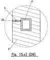
- the guardrail (1) may optionally comprise transverse elements (4a, 4b) diagrammatically shown on the Figures 10.c) , 11.c) and 14.c) .
- Fastening means (5) for these transverse elements (4a, 4b) are shown schematically on the Figure 14.c) .
- These transverse elements (4a, 4b) and these fixing means (5) are similar to those described above in points 1.3 and 1.4 of the description.
Claims (11)
- Schutzgeländer, das aus einer Einheit von montagefertigen Einzelteilen gebildet wird, folgendes umfassend:- zumindest zwei Ständer (2), von denen jeder aus einem vertikalen Flachprofil gebildet wird, das zumindest eine obere Bohrung (21') und eine untere Bohrung (21") umfasst,- zumindest zwei Querelemente (4', 4"), die dazu bestimmt sind, quer zu den Ständern (2) positioniert zu werden: ein oberes Querelement (4') und ein unteres Querelement (4"), wobei ein oberes Querelement (4') dazu bestimmt ist, in die oberen Bohrungen (21') eingeführt zu werden, die in den Ständern (2) ausgeführt sind, und ein unteres Querelement (4") dazu bestimmt ist, in die unteren Bohrungen (21") eingeführt zu werden, die in den Ständern (2) ausgeführt sind, wobei das obere, beziehungsweise das untere Querelement und die besagten oberen, beziehungsweise unteren Bohrungen eine komplementäre Form aufweisen,- zumindest ein temporäres Befestigungsmittel (5) für jedes Querelement (4', 4"), das am Rand eines jeden Ständers (2) angeordnet ist und dazu bestimmt ist, eine Kontaktkraft direkt auf das besagte Querelement auszuüben, um letzteres an die Innenwand der Bohrung (21, 21', 21") zu drücken und für dessen Positionshaltung auf dem besagten Ständer zu sorgen, dadurch gekennzeichnet, dass das besagte Schutzgeländer die folgenden Einzelteile umfasst:- für jeden Ständer (2) eine Platine (3), auf der der besagte Ständer befestigt werden soll,- zumindest eine Platte (6), die dazu bestimmt ist, sich an oder zwischen oder um das obere (4') und untere (4") Querelement anzuordnen.
- Schutzgeländer nach Anspruch 1, wobei die Platte (6) zwischen dem oberen Querelement (4') und dem unteren Querelement (4") eingeführt wird, wobei sich das besagte untere Querelement in Form eines Profils darstellt, das eine horizontale Auflagefläche (41") aufweist, die dazu bestimmt ist, die besagte Platte zu tragen, und eine vertikale Auflagefläche (42"), die dazu bestimmt ist, die besagte Platte entlang der besagten horizontalen Auflagefläche zu führen, wobei sich das besagte obere Querelement in Form eines Profils darstellt, das eine vertikale Auflagefläche (42') aufweist, die dazu bestimmt ist, die besagte Platte in der vertikalen Position zu halten.
- Schutzgeländer nach Anspruch 1, wobei die Platte (6) an den oberen (4') und unteren (4") Querelementen angeordnet ist, wobei sich das besagte untere Querelement in Form eines Profils darstellt, das eine oder mehrere untere Auflageflächen (43") aufweist, die einen unteren Knick (62) der besagten Platte aufnimmt, wobei sich das obere Querelement in Form eines Profils darstellt, das eine oder mehrere obere Auflageflächen (43') aufweist, die dazu bestimmt sind, einen oberen Knick (61) der besagten Platte aufzunehmen.
- Schutzgeländer nach einem der vorherigen Ansprüche, dadurch gekennzeichnet, dass sich das temporäre Befestigungsmittel (5) in Form einer Madenschraube darstellt, die dazu bestimmt ist, in eine Gewindebohrung geschraubt zu werden, die im Rand des Ständers (2) ausgeführt ist, wobei die besagte Gewindebohrung in die Bohrung (21, 21', 21") mündet, wobei das Ende der besagten Madenschraube dazu bestimmt ist, eine Kontaktkraft direkt auf das Querelement (4a, 4b, 4', 4") auszuüben, um letzteres an die Innenwand der Bohrung (21, 21', 21") zu drücken und für dessen Positionshaltung auf dem besagten Ständer zu sorgen.
- Schutzgeländer nach einem der vorherigen Ansprüche, wobei die Platte (6) aus Glas ist, und Dichtungen (8) dazu bestimmt sind, zwischen der besagten Platte (6) und dem oberen Querelement (4') und/ oder dem unteren Querelement (4") angeordnet zu werden, um die besagte Platte (6) zwischen den besagten Querelementen zu verkeilen.
- Schutzgeländer nach einem der vorherigen Ansprüche, wobei die Platinen (3) einen Schlitz (31) aufweisen, in den der untere Abschnitt der Ständer (2) eingeführt werden soll.
- Schutzgeländer nach einem der vorherigen Ansprüche, wobei die Platinen (3) Langlöcher (32) zum Durchführen eines Befestigungsmittels aufweisen, mit dem die besagten Platinen auf dem Boden festgedrückt werden können, wobei die besagten Platinen durch die Langlöcher (32) im Verhältnis zu den besagten Befestigungsmitteln für eine Gleitbewegung am Boden beweglich sind.
- Schutzgeländer nach einem der vorherigen Ansprüche, wobei die Platinen (3) zumindest eine Gewindebohrung (33) aufweisen, in die eine Madenschraube geschraubt werden soll, wobei das Ende der besagten Madenschraube dazu bestimmt ist, eine Kontaktkraft auf den Boden auszuüben, um der Gleitbewegung der besagten Platinen auf dem besagten Boden entgegenzuwirken.
- Schutzgeländer nach einem der vorherigen Ansprüche, wobei das besagte Schutzgeländer als Einzelteile mehrere Querelemente (4a, 4b) umfasst, die dazu bestimmt sind, auf verschiedenen Höhen quer zu den besagten Ständern (2) positioniert zu werden, wobei jedes Querelement (4a, 4b) dazu bestimmt ist, in die Bohrungen (21) eingeführt zu werden, die in den besagten Ständern ausgeführt sind, wobei die besagten Querelemente und die besagten Bohrungen eine komplementäre Form aufweisen.
- Schutzgeländer nach Anspruch 9, wobei das Querelement (4a), das dazu bestimmt ist, ganz oben auf den Ständern (2) angeordnet zu werden, ein Rohr im Durchmesser von zumindest gleich 50 mm mit einer Stärke von zumindest gleich 2 mm ist.
- Schutzgeländer nach Anspruch 10, wobei das oder die Querelemente (4b), die dazu bestimmt sind, unterhalb des obersten Querelements (4a) angeordnet zu werden, Rohre im Durchmesser von zumindest gleich 20 mm mit einer Stärke von zumindest gleich 1,5 mm sind.
Applications Claiming Priority (2)
| Application Number | Priority Date | Filing Date | Title |
|---|---|---|---|
| FR0958108A FR2952664B1 (fr) | 2009-11-17 | 2009-11-17 | Garde-corps constitue d'un ensemble de pieces detachees pretes a etre assemblees. |
| PCT/FR2010/052428 WO2011061436A1 (fr) | 2009-11-17 | 2010-11-16 | Garde-corps constitué d'un ensemble de pièces détachées prêtes à être assemblées |
Publications (2)
| Publication Number | Publication Date |
|---|---|
| EP2501876A1 EP2501876A1 (de) | 2012-09-26 |
| EP2501876B1 true EP2501876B1 (de) | 2016-02-10 |
Family
ID=42246375
Family Applications (1)
| Application Number | Title | Priority Date | Filing Date |
|---|---|---|---|
| EP10795433.1A Active EP2501876B1 (de) | 2009-11-17 | 2010-11-16 | Aus einem satz montagefertiger separater teile geformtes geländer |
Country Status (3)
| Country | Link |
|---|---|
| EP (1) | EP2501876B1 (de) |
| FR (1) | FR2952664B1 (de) |
| WO (1) | WO2011061436A1 (de) |
Families Citing this family (1)
| Publication number | Priority date | Publication date | Assignee | Title |
|---|---|---|---|---|
| DE102015219513B4 (de) | 2015-10-08 | 2022-05-05 | MTU Aero Engines AG | Reparaturverfahren für Dichtsegmente |
Family Cites Families (4)
| Publication number | Priority date | Publication date | Assignee | Title |
|---|---|---|---|---|
| FR2300868A1 (fr) * | 1975-02-13 | 1976-09-10 | Fildier Sa | Procede pour execu |
| FR2659101B1 (fr) * | 1990-03-02 | 1992-07-03 | Di Piro Andre | Poteau de garde-corps. |
| FR2725744A1 (fr) * | 1994-10-13 | 1996-04-19 | Atelier Construction Laplace | Garde-corps pour balcon a profil courbe |
| DE202005006574U1 (de) * | 2005-04-24 | 2005-09-08 | Fleck, Hans-Jürgen | Geländerholm mit in der Steigung stufenlos verstellbare Handlauf- und Knieleistenaufnahme |
-
2009
- 2009-11-17 FR FR0958108A patent/FR2952664B1/fr not_active Expired - Fee Related
-
2010
- 2010-11-16 EP EP10795433.1A patent/EP2501876B1/de active Active
- 2010-11-16 WO PCT/FR2010/052428 patent/WO2011061436A1/fr active Application Filing
Also Published As
| Publication number | Publication date |
|---|---|
| WO2011061436A4 (fr) | 2011-07-14 |
| WO2011061436A1 (fr) | 2011-05-26 |
| FR2952664B1 (fr) | 2012-05-04 |
| EP2501876A1 (de) | 2012-09-26 |
| FR2952664A1 (fr) | 2011-05-20 |
Similar Documents
| Publication | Publication Date | Title |
|---|---|---|
| EP2149648A1 (de) | Vorrichtung zur Befestigung von Dacheindeckungsplatten | |
| EP3492675B1 (de) | Vorrichtung zum befestigen von lamellen an einem starren gitterpaneel, lamellenbefestigungskit an einem starren gitterpaneel und sichtschutzzaun, der mit diesem kit ausgestattet ist | |
| FR2945064A1 (fr) | Dispositif a lames brise-vue equipe de moyens de retenue des lames et lame correspondante | |
| EP2270290A1 (de) | Befestigungsvorrichtung für Boden | |
| EP2501876B1 (de) | Aus einem satz montagefertiger separater teile geformtes geländer | |
| CA2194871A1 (fr) | Escalier a configuration variable | |
| CA2973677A1 (fr) | Dispositif de fixation de panneau solaire | |
| FR2908178A1 (fr) | Assemblage de deux profiles creux perpendiculaires | |
| FR3062865A1 (fr) | Procede de montage d'un revetement souple tendu sur un cadre de fixation et cadre de fixation pour la mise en oeuvre dudit procede | |
| FR2994902A1 (fr) | Glissiere et procede de realisation d'une glissiere pour siege de vehicule automobile | |
| EP2265829B1 (de) | Struktur mit mindestens einer an einem vertikalen pfosten befestigten horizontalen rohrförmigen querstrebe | |
| EP3810866A1 (de) | Verfahren zur herstellung einer verkleidung | |
| FR2883313A1 (fr) | Ossature de cloison demontable ou amovible a double paroi | |
| WO2015036696A1 (fr) | Systeme de fixation pour la realisation de revetements tendus | |
| BE1016764A6 (fr) | Ensemble de profiles. | |
| EP2597222B1 (de) | Blindwand umfassend gespannte Stoffe, die durch eine Trennleiste miteinander verbunden sind | |
| FR2966481A1 (fr) | Garde-corps constitue d'un ensemble de pieces detachees pretes a etre assemblees et comportant au moins une jardiniere. | |
| FR2994999A1 (fr) | Ouvrant de porte ou de fenetre | |
| FR3056626A1 (fr) | Structure de verriere equipee d'un profile d'angle | |
| FR3020649A1 (fr) | Abri de piscine a modules telescopiques comprenant un mecanisme de deplacement ameliore des modules | |
| EP2456930B1 (de) | System zur befestigung einer falschen wand mithilfe einer kleinen pfette | |
| EP3074641B1 (de) | Verbindung einer führung mit einer länglichen lippe in einem länglichen schlitz und anwendung auf eine verbindung einer luftführung mit einer düse | |
| EP2873785B1 (de) | Fuß für selbsttragendes Geländer | |
| FR2738862A1 (fr) | Barriere modulable | |
| EP2280137A1 (de) | Geländerstab, der mit einem Sicherheitsschieber ausgestattet ist, und entsprechender Sicherheitsschieber |
Legal Events
| Date | Code | Title | Description |
|---|---|---|---|
| PUAI | Public reference made under article 153(3) epc to a published international application that has entered the european phase |
Free format text: ORIGINAL CODE: 0009012 |
|
| 17P | Request for examination filed |
Effective date: 20120403 |
|
| AK | Designated contracting states |
Kind code of ref document: A1 Designated state(s): AL AT BE BG CH CY CZ DE DK EE ES FI FR GB GR HR HU IE IS IT LI LT LU LV MC MK MT NL NO PL PT RO RS SE SI SK SM TR |
|
| DAX | Request for extension of the european patent (deleted) | ||
| 111L | Licence recorded |
Designated state(s): AL AT BE BG CH CY CZ DE DK EE ES FI FR GB GR HR HU IE IS IT LT LU LV MC MK MT NL NO PL PT RO RS SE SI SK SM TR Name of requester: MOYO, FR Effective date: 20140707 |
|
| RAP1 | Party data changed (applicant data changed or rights of an application transferred) |
Owner name: DANI ALU |
|
| RIN1 | Information on inventor provided before grant (corrected) |
Inventor name: MOYO, ANDRE |
|
| GRAP | Despatch of communication of intention to grant a patent |
Free format text: ORIGINAL CODE: EPIDOSNIGR1 |
|
| INTG | Intention to grant announced |
Effective date: 20150817 |
|
| GRAS | Grant fee paid |
Free format text: ORIGINAL CODE: EPIDOSNIGR3 |
|
| GRAA | (expected) grant |
Free format text: ORIGINAL CODE: 0009210 |
|
| 111L | Licence recorded |
Designated state(s): AL AT BE BG CH CY CZ DE DK EE ES FI FR GB GR HR HU IE IS IT LT LU LV MC MK MT NL NO PL PT RO RS SE SI SK SM TR Name of requester: MOYO, FR Effective date: 20140707 |
|
| AK | Designated contracting states |
Kind code of ref document: B1 Designated state(s): AL AT BE BG CH CY CZ DE DK EE ES FI FR GB GR HR HU IE IS IT LI LT LU LV MC MK MT NL NO PL PT RO RS SE SI SK SM TR |
|
| REG | Reference to a national code |
Ref country code: GB Ref legal event code: FG4D Free format text: NOT ENGLISH |
|
| REG | Reference to a national code |
Ref country code: CH Ref legal event code: PK Free format text: COMPLETEMENT D'ENREGISTREMENT DE LICENCE: LICENCE NON-EXCLUSIVE Ref country code: AT Ref legal event code: REF Ref document number: 774732 Country of ref document: AT Kind code of ref document: T Effective date: 20160215 Ref country code: CH Ref legal event code: EP |
|
| REG | Reference to a national code |
Ref country code: IE Ref legal event code: FG4D Free format text: LANGUAGE OF EP DOCUMENT: FRENCH |
|
| REG | Reference to a national code |
Ref country code: DE Ref legal event code: R096 Ref document number: 602010030595 Country of ref document: DE |
|
| REG | Reference to a national code |
Ref country code: LT Ref legal event code: MG4D |
|
| REG | Reference to a national code |
Ref country code: NL Ref legal event code: MP Effective date: 20160210 |
|
| REG | Reference to a national code |
Ref country code: AT Ref legal event code: MK05 Ref document number: 774732 Country of ref document: AT Kind code of ref document: T Effective date: 20160210 |
|
| PG25 | Lapsed in a contracting state [announced via postgrant information from national office to epo] |
Ref country code: ES Free format text: LAPSE BECAUSE OF FAILURE TO SUBMIT A TRANSLATION OF THE DESCRIPTION OR TO PAY THE FEE WITHIN THE PRESCRIBED TIME-LIMIT Effective date: 20160210 Ref country code: NO Free format text: LAPSE BECAUSE OF FAILURE TO SUBMIT A TRANSLATION OF THE DESCRIPTION OR TO PAY THE FEE WITHIN THE PRESCRIBED TIME-LIMIT Effective date: 20160510 Ref country code: HR Free format text: LAPSE BECAUSE OF FAILURE TO SUBMIT A TRANSLATION OF THE DESCRIPTION OR TO PAY THE FEE WITHIN THE PRESCRIBED TIME-LIMIT Effective date: 20160210 Ref country code: GR Free format text: LAPSE BECAUSE OF FAILURE TO SUBMIT A TRANSLATION OF THE DESCRIPTION OR TO PAY THE FEE WITHIN THE PRESCRIBED TIME-LIMIT Effective date: 20160511 Ref country code: FI Free format text: LAPSE BECAUSE OF FAILURE TO SUBMIT A TRANSLATION OF THE DESCRIPTION OR TO PAY THE FEE WITHIN THE PRESCRIBED TIME-LIMIT Effective date: 20160210 Ref country code: IT Free format text: LAPSE BECAUSE OF FAILURE TO SUBMIT A TRANSLATION OF THE DESCRIPTION OR TO PAY THE FEE WITHIN THE PRESCRIBED TIME-LIMIT Effective date: 20160210 |
|
| REG | Reference to a national code |
Ref country code: FR Ref legal event code: PLFP Year of fee payment: 7 |
|
| PG25 | Lapsed in a contracting state [announced via postgrant information from national office to epo] |
Ref country code: SE Free format text: LAPSE BECAUSE OF FAILURE TO SUBMIT A TRANSLATION OF THE DESCRIPTION OR TO PAY THE FEE WITHIN THE PRESCRIBED TIME-LIMIT Effective date: 20160210 Ref country code: NL Free format text: LAPSE BECAUSE OF FAILURE TO SUBMIT A TRANSLATION OF THE DESCRIPTION OR TO PAY THE FEE WITHIN THE PRESCRIBED TIME-LIMIT Effective date: 20160210 Ref country code: LV Free format text: LAPSE BECAUSE OF FAILURE TO SUBMIT A TRANSLATION OF THE DESCRIPTION OR TO PAY THE FEE WITHIN THE PRESCRIBED TIME-LIMIT Effective date: 20160210 Ref country code: PT Free format text: LAPSE BECAUSE OF FAILURE TO SUBMIT A TRANSLATION OF THE DESCRIPTION OR TO PAY THE FEE WITHIN THE PRESCRIBED TIME-LIMIT Effective date: 20160613 Ref country code: IS Free format text: LAPSE BECAUSE OF FAILURE TO SUBMIT A TRANSLATION OF THE DESCRIPTION OR TO PAY THE FEE WITHIN THE PRESCRIBED TIME-LIMIT Effective date: 20160610 Ref country code: RS Free format text: LAPSE BECAUSE OF FAILURE TO SUBMIT A TRANSLATION OF THE DESCRIPTION OR TO PAY THE FEE WITHIN THE PRESCRIBED TIME-LIMIT Effective date: 20160210 Ref country code: AT Free format text: LAPSE BECAUSE OF FAILURE TO SUBMIT A TRANSLATION OF THE DESCRIPTION OR TO PAY THE FEE WITHIN THE PRESCRIBED TIME-LIMIT Effective date: 20160210 Ref country code: LT Free format text: LAPSE BECAUSE OF FAILURE TO SUBMIT A TRANSLATION OF THE DESCRIPTION OR TO PAY THE FEE WITHIN THE PRESCRIBED TIME-LIMIT Effective date: 20160210 Ref country code: PL Free format text: LAPSE BECAUSE OF FAILURE TO SUBMIT A TRANSLATION OF THE DESCRIPTION OR TO PAY THE FEE WITHIN THE PRESCRIBED TIME-LIMIT Effective date: 20160210 |
|
| PG25 | Lapsed in a contracting state [announced via postgrant information from national office to epo] |
Ref country code: DK Free format text: LAPSE BECAUSE OF FAILURE TO SUBMIT A TRANSLATION OF THE DESCRIPTION OR TO PAY THE FEE WITHIN THE PRESCRIBED TIME-LIMIT Effective date: 20160210 Ref country code: EE Free format text: LAPSE BECAUSE OF FAILURE TO SUBMIT A TRANSLATION OF THE DESCRIPTION OR TO PAY THE FEE WITHIN THE PRESCRIBED TIME-LIMIT Effective date: 20160210 |
|
| REG | Reference to a national code |
Ref country code: DE Ref legal event code: R097 Ref document number: 602010030595 Country of ref document: DE |
|
| PG25 | Lapsed in a contracting state [announced via postgrant information from national office to epo] |
Ref country code: CZ Free format text: LAPSE BECAUSE OF FAILURE TO SUBMIT A TRANSLATION OF THE DESCRIPTION OR TO PAY THE FEE WITHIN THE PRESCRIBED TIME-LIMIT Effective date: 20160210 Ref country code: SK Free format text: LAPSE BECAUSE OF FAILURE TO SUBMIT A TRANSLATION OF THE DESCRIPTION OR TO PAY THE FEE WITHIN THE PRESCRIBED TIME-LIMIT Effective date: 20160210 Ref country code: RO Free format text: LAPSE BECAUSE OF FAILURE TO SUBMIT A TRANSLATION OF THE DESCRIPTION OR TO PAY THE FEE WITHIN THE PRESCRIBED TIME-LIMIT Effective date: 20160210 Ref country code: SM Free format text: LAPSE BECAUSE OF FAILURE TO SUBMIT A TRANSLATION OF THE DESCRIPTION OR TO PAY THE FEE WITHIN THE PRESCRIBED TIME-LIMIT Effective date: 20160210 |
|
| PLBE | No opposition filed within time limit |
Free format text: ORIGINAL CODE: 0009261 |
|
| STAA | Information on the status of an ep patent application or granted ep patent |
Free format text: STATUS: NO OPPOSITION FILED WITHIN TIME LIMIT |
|
| 26N | No opposition filed |
Effective date: 20161111 |
|
| PG25 | Lapsed in a contracting state [announced via postgrant information from national office to epo] |
Ref country code: SI Free format text: LAPSE BECAUSE OF FAILURE TO SUBMIT A TRANSLATION OF THE DESCRIPTION OR TO PAY THE FEE WITHIN THE PRESCRIBED TIME-LIMIT Effective date: 20160210 Ref country code: BE Free format text: LAPSE BECAUSE OF NON-PAYMENT OF DUE FEES Effective date: 20161130 Ref country code: BG Free format text: LAPSE BECAUSE OF FAILURE TO SUBMIT A TRANSLATION OF THE DESCRIPTION OR TO PAY THE FEE WITHIN THE PRESCRIBED TIME-LIMIT Effective date: 20160510 |
|
| REG | Reference to a national code |
Ref country code: CH Ref legal event code: PL |
|
| PG25 | Lapsed in a contracting state [announced via postgrant information from national office to epo] |
Ref country code: CH Free format text: LAPSE BECAUSE OF NON-PAYMENT OF DUE FEES Effective date: 20161130 Ref country code: LI Free format text: LAPSE BECAUSE OF NON-PAYMENT OF DUE FEES Effective date: 20161130 |
|
| REG | Reference to a national code |
Ref country code: IE Ref legal event code: MM4A |
|
| REG | Reference to a national code |
Ref country code: FR Ref legal event code: PLFP Year of fee payment: 8 |
|
| PG25 | Lapsed in a contracting state [announced via postgrant information from national office to epo] |
Ref country code: LU Free format text: LAPSE BECAUSE OF NON-PAYMENT OF DUE FEES Effective date: 20161130 |
|
| PG25 | Lapsed in a contracting state [announced via postgrant information from national office to epo] |
Ref country code: IE Free format text: LAPSE BECAUSE OF NON-PAYMENT OF DUE FEES Effective date: 20161116 |
|
| REG | Reference to a national code |
Ref country code: BE Ref legal event code: MM Effective date: 20161130 |
|
| PG25 | Lapsed in a contracting state [announced via postgrant information from national office to epo] |
Ref country code: CY Free format text: LAPSE BECAUSE OF FAILURE TO SUBMIT A TRANSLATION OF THE DESCRIPTION OR TO PAY THE FEE WITHIN THE PRESCRIBED TIME-LIMIT Effective date: 20160210 Ref country code: HU Free format text: LAPSE BECAUSE OF FAILURE TO SUBMIT A TRANSLATION OF THE DESCRIPTION OR TO PAY THE FEE WITHIN THE PRESCRIBED TIME-LIMIT; INVALID AB INITIO Effective date: 20101116 |
|
| PG25 | Lapsed in a contracting state [announced via postgrant information from national office to epo] |
Ref country code: MK Free format text: LAPSE BECAUSE OF FAILURE TO SUBMIT A TRANSLATION OF THE DESCRIPTION OR TO PAY THE FEE WITHIN THE PRESCRIBED TIME-LIMIT Effective date: 20160210 Ref country code: TR Free format text: LAPSE BECAUSE OF FAILURE TO SUBMIT A TRANSLATION OF THE DESCRIPTION OR TO PAY THE FEE WITHIN THE PRESCRIBED TIME-LIMIT Effective date: 20160210 Ref country code: MC Free format text: LAPSE BECAUSE OF FAILURE TO SUBMIT A TRANSLATION OF THE DESCRIPTION OR TO PAY THE FEE WITHIN THE PRESCRIBED TIME-LIMIT Effective date: 20160210 |
|
| PG25 | Lapsed in a contracting state [announced via postgrant information from national office to epo] |
Ref country code: MT Free format text: LAPSE BECAUSE OF FAILURE TO SUBMIT A TRANSLATION OF THE DESCRIPTION OR TO PAY THE FEE WITHIN THE PRESCRIBED TIME-LIMIT Effective date: 20160210 |
|
| REG | Reference to a national code |
Ref country code: FR Ref legal event code: PLFP Year of fee payment: 9 |
|
| PG25 | Lapsed in a contracting state [announced via postgrant information from national office to epo] |
Ref country code: AL Free format text: LAPSE BECAUSE OF FAILURE TO SUBMIT A TRANSLATION OF THE DESCRIPTION OR TO PAY THE FEE WITHIN THE PRESCRIBED TIME-LIMIT Effective date: 20160210 |
|
| PGFP | Annual fee paid to national office [announced via postgrant information from national office to epo] |
Ref country code: GB Payment date: 20210915 Year of fee payment: 12 |
|
| PGFP | Annual fee paid to national office [announced via postgrant information from national office to epo] |
Ref country code: DE Payment date: 20210920 Year of fee payment: 12 |
|
| REG | Reference to a national code |
Ref country code: DE Ref legal event code: R119 Ref document number: 602010030595 Country of ref document: DE |
|
| GBPC | Gb: european patent ceased through non-payment of renewal fee |
Effective date: 20221116 |
|
| PG25 | Lapsed in a contracting state [announced via postgrant information from national office to epo] |
Ref country code: GB Free format text: LAPSE BECAUSE OF NON-PAYMENT OF DUE FEES Effective date: 20221116 Ref country code: DE Free format text: LAPSE BECAUSE OF NON-PAYMENT OF DUE FEES Effective date: 20230601 |
|
| PGFP | Annual fee paid to national office [announced via postgrant information from national office to epo] |
Ref country code: FR Payment date: 20230915 Year of fee payment: 14 |