EP2501632B1 - Guide arrangement having a transport member - Google Patents
Guide arrangement having a transport member Download PDFInfo
- Publication number
- EP2501632B1 EP2501632B1 EP10779451.3A EP10779451A EP2501632B1 EP 2501632 B1 EP2501632 B1 EP 2501632B1 EP 10779451 A EP10779451 A EP 10779451A EP 2501632 B1 EP2501632 B1 EP 2501632B1
- Authority
- EP
- European Patent Office
- Prior art keywords
- guide
- elements
- guide rail
- arrangement according
- running surface
- Prior art date
- Legal status (The legal status is an assumption and is not a legal conclusion. Google has not performed a legal analysis and makes no representation as to the accuracy of the status listed.)
- Active
Links
- 230000007704 transition Effects 0.000 claims description 6
- 230000000295 complement effect Effects 0.000 claims description 5
- 238000005096 rolling process Methods 0.000 claims description 4
- 230000008878 coupling Effects 0.000 description 38
- 238000010168 coupling process Methods 0.000 description 38
- 238000005859 coupling reaction Methods 0.000 description 38
- 238000003780 insertion Methods 0.000 description 27
- 230000037431 insertion Effects 0.000 description 27
- 210000000056 organ Anatomy 0.000 description 23
- 230000000712 assembly Effects 0.000 description 11
- 238000000429 assembly Methods 0.000 description 11
- 238000009434 installation Methods 0.000 description 8
- 238000013461 design Methods 0.000 description 6
- 239000000463 material Substances 0.000 description 6
- 239000004033 plastic Substances 0.000 description 6
- 229920003023 plastic Polymers 0.000 description 6
- 238000012545 processing Methods 0.000 description 6
- 238000004519 manufacturing process Methods 0.000 description 5
- 230000015572 biosynthetic process Effects 0.000 description 4
- 230000006872 improvement Effects 0.000 description 4
- 238000000034 method Methods 0.000 description 4
- 238000000926 separation method Methods 0.000 description 4
- 238000010276 construction Methods 0.000 description 3
- 238000005520 cutting process Methods 0.000 description 3
- 229920002430 Fibre-reinforced plastic Polymers 0.000 description 2
- 230000008901 benefit Effects 0.000 description 2
- 230000006378 damage Effects 0.000 description 2
- 238000006073 displacement reaction Methods 0.000 description 2
- 239000011151 fibre-reinforced plastic Substances 0.000 description 2
- 238000007373 indentation Methods 0.000 description 2
- 238000002347 injection Methods 0.000 description 2
- 239000007924 injection Substances 0.000 description 2
- 238000005457 optimization Methods 0.000 description 2
- 230000008569 process Effects 0.000 description 2
- 230000009467 reduction Effects 0.000 description 2
- 238000003860 storage Methods 0.000 description 2
- 241000446313 Lamella Species 0.000 description 1
- 239000004952 Polyamide Substances 0.000 description 1
- 206010038743 Restlessness Diseases 0.000 description 1
- 239000004809 Teflon Substances 0.000 description 1
- 229920006362 Teflon® Polymers 0.000 description 1
- 208000027418 Wounds and injury Diseases 0.000 description 1
- 230000001154 acute effect Effects 0.000 description 1
- 238000004026 adhesive bonding Methods 0.000 description 1
- 238000013459 approach Methods 0.000 description 1
- 230000009286 beneficial effect Effects 0.000 description 1
- 230000001427 coherent effect Effects 0.000 description 1
- 238000011109 contamination Methods 0.000 description 1
- 238000011161 development Methods 0.000 description 1
- 230000009977 dual effect Effects 0.000 description 1
- 238000005516 engineering process Methods 0.000 description 1
- 230000002349 favourable effect Effects 0.000 description 1
- 208000014674 injury Diseases 0.000 description 1
- 239000002184 metal Substances 0.000 description 1
- 239000007769 metal material Substances 0.000 description 1
- 238000003032 molecular docking Methods 0.000 description 1
- 238000000465 moulding Methods 0.000 description 1
- 229920002647 polyamide Polymers 0.000 description 1
- 230000000284 resting effect Effects 0.000 description 1
Images


Classifications
-
- B—PERFORMING OPERATIONS; TRANSPORTING
- B65—CONVEYING; PACKING; STORING; HANDLING THIN OR FILAMENTARY MATERIAL
- B65G—TRANSPORT OR STORAGE DEVICES, e.g. CONVEYORS FOR LOADING OR TIPPING, SHOP CONVEYOR SYSTEMS OR PNEUMATIC TUBE CONVEYORS
- B65G17/00—Conveyors having an endless traction element, e.g. a chain, transmitting movement to a continuous or substantially-continuous load-carrying surface or to a series of individual load-carriers; Endless-chain conveyors in which the chains form the load-carrying surface
- B65G17/20—Conveyors having an endless traction element, e.g. a chain, transmitting movement to a continuous or substantially-continuous load-carrying surface or to a series of individual load-carriers; Endless-chain conveyors in which the chains form the load-carrying surface comprising load-carriers suspended from overhead traction chains
-
- B—PERFORMING OPERATIONS; TRANSPORTING
- B65—CONVEYING; PACKING; STORING; HANDLING THIN OR FILAMENTARY MATERIAL
- B65G—TRANSPORT OR STORAGE DEVICES, e.g. CONVEYORS FOR LOADING OR TIPPING, SHOP CONVEYOR SYSTEMS OR PNEUMATIC TUBE CONVEYORS
- B65G17/00—Conveyors having an endless traction element, e.g. a chain, transmitting movement to a continuous or substantially-continuous load-carrying surface or to a series of individual load-carriers; Endless-chain conveyors in which the chains form the load-carrying surface
- B65G17/30—Details; Auxiliary devices
- B65G17/32—Individual load-carriers
-
- B—PERFORMING OPERATIONS; TRANSPORTING
- B65—CONVEYING; PACKING; STORING; HANDLING THIN OR FILAMENTARY MATERIAL
- B65G—TRANSPORT OR STORAGE DEVICES, e.g. CONVEYORS FOR LOADING OR TIPPING, SHOP CONVEYOR SYSTEMS OR PNEUMATIC TUBE CONVEYORS
- B65G21/00—Supporting or protective framework or housings for endless load-carriers or traction elements of belt or chain conveyors
- B65G21/16—Supporting or protective framework or housings for endless load-carriers or traction elements of belt or chain conveyors for conveyors having endless load-carriers movable in curved paths
- B65G21/18—Supporting or protective framework or housings for endless load-carriers or traction elements of belt or chain conveyors for conveyors having endless load-carriers movable in curved paths in three-dimensionally curved paths
-
- B—PERFORMING OPERATIONS; TRANSPORTING
- B65—CONVEYING; PACKING; STORING; HANDLING THIN OR FILAMENTARY MATERIAL
- B65G—TRANSPORT OR STORAGE DEVICES, e.g. CONVEYORS FOR LOADING OR TIPPING, SHOP CONVEYOR SYSTEMS OR PNEUMATIC TUBE CONVEYORS
- B65G23/00—Driving gear for endless conveyors; Belt- or chain-tensioning arrangements
- B65G23/02—Belt- or chain-engaging elements
- B65G23/14—Endless driving elements extending parallel to belt or chain
-
- B—PERFORMING OPERATIONS; TRANSPORTING
- B65—CONVEYING; PACKING; STORING; HANDLING THIN OR FILAMENTARY MATERIAL
- B65H—HANDLING THIN OR FILAMENTARY MATERIAL, e.g. SHEETS, WEBS, CABLES
- B65H29/00—Delivering or advancing articles from machines; Advancing articles to or into piles
- B65H29/003—Delivering or advancing articles from machines; Advancing articles to or into piles by grippers
-
- B—PERFORMING OPERATIONS; TRANSPORTING
- B65—CONVEYING; PACKING; STORING; HANDLING THIN OR FILAMENTARY MATERIAL
- B65H—HANDLING THIN OR FILAMENTARY MATERIAL, e.g. SHEETS, WEBS, CABLES
- B65H2405/00—Parts for holding the handled material
- B65H2405/50—Gripping means
- B65H2405/55—Rail guided gripping means running in closed loop, e.g. without permanent interconnecting means
- B65H2405/552—Rail guided gripping means running in closed loop, e.g. without permanent interconnecting means with permanent interconnection and determined spacing between the grippers
- B65H2405/5521—Rail guided gripping means running in closed loop, e.g. without permanent interconnecting means with permanent interconnection and determined spacing between the grippers details of interconnection, e.g. chain, link
-
- B—PERFORMING OPERATIONS; TRANSPORTING
- B65—CONVEYING; PACKING; STORING; HANDLING THIN OR FILAMENTARY MATERIAL
- B65H—HANDLING THIN OR FILAMENTARY MATERIAL, e.g. SHEETS, WEBS, CABLES
- B65H29/00—Delivering or advancing articles from machines; Advancing articles to or into piles
Definitions
- the invention relates to a guide arrangement for guiding the movement of a product for conveying products according to the preamble of claim 1.
- the DE 2 347 459 discloses such a guide arrangement.
- Conveying devices with a conveyor chain guided by means of a suitable guide arrangement along a preferably endlessly circulating conveying path are used for transporting printed products between individual processing stations, such as inserting machines, addressing devices, gluing machines, etc.
- the printed products are usually held by grippers or clamps mounted on the chain links and, if appropriate, released from the grippers at the processing stations.
- the conveyor chain is usually driven endlessly circumferentially along the conveying path defined by the guide arrangement.
- the conveyor line usually has straight and arcuate sections, wherein the arcuate sections may be arranged within a horizontal plane, a vertical plane or an obliquely upwardly or downwardly extending plane.
- the guide arrangement must also have rectilinear and arc-shaped guide elements, by means of which the arcs of the conveying path are determined.
- the conveyor line can extend over a length of 100 m or more and thereby pass through an entire production space in the horizontal and vertical directions. Therefore, the guiding arrangement serving to define the conveying path can not be manufactured in one piece, but must be composed of individual guide elements interconnected by means of suitable connecting arrangements. Corresponding guide arrangements are, for example, in the WO 99/33731 . EP 1 029 815 A1 . WO 99/33722 . WO 99/33732 . WO 99/33730 described. When mounting the known guide arrangements, the individual guide elements are usually combined on the end surface side and connected by means of engaging in the side walls of the guide elements clamping devices, which in turn od via connecting elements in the form of bolts. Like. Connected to each other, firmly connected.
- the present invention seeks to provide a guide assembly for guiding the movement of a designed for conveying printed products conveyor chain, which is easy to install while ensuring low-noise and low-wear operation, and to provide a conveyor with such a guide arrangement.
- the invention aims to remedy this situation.
- the invention as characterized in the claims, the object is to propose a guide arrangement, which is able to overcome the disadvantages of belonging to the prior art arrangements.
- the object of the invention is also to provide a guide arrangement, which can be operated without further including with belonging to the prior art transport organs.
- the inventive guide arrangement is therefore designed according to the task not only for a special tailored transport organ. Another task The invention is to ensure a low-noise and wear-minimized operation.
- connecting elements are positively fixed to the transversely, in particular approximately perpendicularly, the conveyor track extending end faces of the individual guide elements, which can then be connected in the correct position by positive engagement with each other.
- the determination of the connecting elements on the guide elements can be made at the factory, so that the components consisting of guide element and connecting elements can be prefabricated by resorting to standard components, such as linearly extending guide elements, arcuate guide elements and connecting elements. In this case, a smooth transition from guide element to connecting element can be ensured in the factory pre-assembly.
- the prefabricated assemblies in the area facing each other surface side, d.
- the positive engagement of mutually facing end-face contact surfaces of the fasteners fixed to the guide elements can be achieved if a contact surface has at least one projection and the other contact surface at least one positive fit receiving the projection complementary thereto formed recess and / or recess.
- the connecting elements usually have a substantially flat boundary surface facing the guide element and a contact surface extending approximately parallel to this flat boundary surface, wherein a projection of the contact surface extends approximately along the conveying path into that of the guide element facing boundary surface extends opposite, while the recess extends in the direction of the guide element facing the boundary surface.
- each contact surface has at least one projection and at least one recess such that a positive connection can be effected in the region of two mutually facing uniform contact surfaces .
- projection and recess of the contact surface are preferably mirror-symmetrical with respect to a straight line running perpendicular to the conveyor line.
- a projection in a sectional plane running perpendicular to the conveying direction has a cross-sectional area tapering in the direction of the adjacent contact surface or depression wherein the recess intended to receive the projection may also have a correspondingly tapering cross-sectional area.
- At least one projection and the complementary recess to have a cross-sectional surface which counteracts a rotational movement about a rotation axis extending parallel to the conveying direction in a sectional plane extending perpendicularly to the conveying direction, ie. H. if this cross-sectional area deviates from a circular disk or ring shape.
- An improvement in the mounting accuracy can be achieved if at least one contact surface has two, three or more projections which are positively received in the mounted state in correspondingly complementary recesses or recesses of the other contact surface.
- connection arrangement serving for coupling the connecting elements in the region of the contact surfaces , Preferably accessible from the outside, mounting arrangement, with which the positive connection of the connecting elements can be secured.
- Such a fastening arrangement can be realized in a particularly simple manner in the form of a fastening bolt extending in parallel to the conveying path, passing through a connecting element and inserted in a thread which is preferably inserted into the adjacent connecting element, such as a threaded nut accessible from the outside, in particular a screw bolt.
- a fastening bolt is received in a groove-shaped recess formed in an outer boundary surface of the guide element and extending along the conveying path, in which the bolt head is accessible, for example, for an Allen wrench is.
- the threaded nut can be secured against rotation in a corresponding receptacle in one of the connecting elements.
- the fastening bolts are inserted into corresponding recesses in the connecting elements, wherein the locking of the fastening bolts in the corresponding recesses of the connecting elements by means of a snap connection can be made. Thereafter, the locking element is pushed onto outside of the connecting elements exposed areas of the fastening bolts, so as to secure the positive connection of the connecting elements.
- the fastening arrangement just described is carried out on the model of a chain lock, wherein all components, including the locking element, can be recessed in an outer boundary surface of the fastening elements, so as to avoid projecting parts of the guide assembly.
- the fastening bolts can first be connected to one another via the locking element formed, for example, in the manner of a U-bracket, and then inserted into the receptacles of the connecting elements. This can be advantageous in difficult installation conditions.
- At least one projection has an angular cross-section in a sectional plane running perpendicular to the conveying path, wherein the then existing legs of the projection can enclose a right angle with each other, so as to provide a particularly high transverse rigidity in mutually perpendicular directions.
- the guide elements of the guide arrangement serve not only the leadership of the conveying member along the conveying path, but also the protection of the conveying member from contamination and mechanical loads.
- the guide elements and the connecting elements delimit a guide channel extending along the conveying path and designed to receive the conveying member and open on one side.
- Guide elements and connecting elements are designed in this embodiment of the invention in a direction perpendicular to the conveying section cutting plane substantially C-shaped, wherein the continuously along the conveying path extending opening of the guide channel serves to the passage of defined on the conveying member functional means, such as brackets or grippers to capture printed products.
- a guide assembly for guiding the movement of a designed for conveying printed products conveying member, which consists of a number of transport organs, along a preferably endless circulating conveyor line with a plurality of a Provided along the conveying path, designed for receiving the conveyor chain and open on one side guide channel limiting guide elements, which is characterized essentially in that four or more with four or more arranged on individual chain links of the transport member guide means, esp.
- each guide element within the guide channel co-operating guide surfaces are arranged, which extend along the conveying path.
- a separate guide surface is provided for each guide means so as to help avoid the tilting of the transport member with respect to the guide arrangement particularly reliable.
- the correspondingly executed guide elements with the aid of the above-described connecting elements can be positively connected to each other, so that the particularly tamper-proof guide of the transport member can be provided while avoiding excessive installation work.
- a second guide surface of the guide elements of a pivoting movement of the transport member cooperating with a second guide means of the transport member with respect to a parallel to the conveyor line and parallel to a first guide surface a pivot axis extending therefrom in a first pivoting direction counteracts, transversely, in particular approximately perpendicular, to the first guide surface in a first pivoting direction.
- the first and the second guide surface are preferably arranged at a right angle to each other enclosing planes, so that for corresponding guide means of the transport member support surfaces in two transverse, in particular approximately perpendicular, mutually extending support directions are provided.
- a further improvement in the anti-tilting of the guide arrangement can be achieved if a third guide surface extending approximately parallel to the second guide surface cooperatively counteracts a third guide device of the conveyor member with a pivoting movement relative to the pivot axis in the first pivoting direction.
- the third guide surface for providing a play-free guidance of the transport member is expediently spaced in a direction perpendicular thereto from the second guide surface, that the transport member with the voltage applied to the second guide surface second guide means and the third guide surface adjacent third guide means play-free with respect to a is guided perpendicular to the second and / or third guide surface extending direction between these guide surfaces.
- a play-free and at the same time frictionless guidance can be carried out using guide means in the form of rotatable with respect to predetermined roller axes guide rollers.
- the second guide roller may be spaced from the third guide roller in a direction perpendicular to the first guide surface direction.
- a particularly precise guidance of the transport member along the conveying path can be achieved if a fourth guide surface cooperates with a fourth guide device of the transport member abutting the pivoting movement of the transport member with respect to the pivot axis in a second opposite direction of the first pivoting direction Counteracts pivoting direction and transverse, in particular approximately perpendicular, to the second guide surface and preferably runs approximately parallel to the first guide surface. This completely counteracts any pivoting or tilting of the transport member with respect to a pivoting or tilting axis extending parallel to the conveying path.
- the fourth guide surface is spaced in a direction perpendicular thereto in such a direction from the first guide surface, that the transport member with the voltage applied to the fourth guide surface fourth guide means and the the first guide surface adjacent first guide means is guided without play with respect to a direction perpendicular to the first and / or fourth guide surface extending direction.
- the arrangement of the guide surfaces just described is particularly useful in the region of rectilinear sections of the guide track, because in this area with the four guide surfaces described a play-free and secured against tilting guidance of the transport member can be done. Care must be taken in the region of arcuate sections of the conveying path that the tracking error occurring in the bow regions of the transport member or the guide elements arranged on the transport member does not lead to excessive wear. In this context, it is expedient if the guide means of the transport organ with minor Game are guided between guide surfaces of the guide arrangement.
- Such a guide can be ensured if in the guide channel a with a distance approximately parallel to the first and preferably coplanar to the fourth guide surface extending fifth guide surface, a distance approximately parallel to the second and preferably approximately coplanar to the third guide surface extending sixth guide surface, a distance is provided approximately parallel to the third and preferably approximately coplanar with the second guide surface extending seventh guide surface and / or a distance approximately parallel to the fourth and preferably approximately coplanar to the first guide surface extending eighth guide surface.
- a first guide roller of the transport member between the first and the fifth guide surface, a second guide roller of the transport member between the second and the sixth guide surface, a third guide roller of the transport member between the third and the seventh guide surface and a fourth guide roller of the transport member between the fourth and the eighth guide surface may be arranged, wherein all guide rollers may be arranged with slight play between the guide surfaces, so as to minimize a wear caused by tracking error.
- the guide surfaces of the guide elements guide surfaces of the connecting elements are assigned, in which pass over the guide surfaces of the guide elements.
- These guide surfaces of the connecting elements are formed according to the invention by releasably fixable in recesses of the connecting elements adapter elements.
- the adapter elements can simultaneously form projections of the connecting elements, which contribute to the positive connection of the connecting elements.
- At least one guide surface is formed by a releasably fixed to a support portion of a guide element tread element. From an assembly point of view, it has proven to be expedient in this context if the carrier area is formed in the form of a section extending along the conveying path and in a section plane T-shaped extending perpendicularly thereto and the tread element is in the form of a C-shaped bridge which can be pushed onto the T-shaped web. Profile is formed.
- an adapter element fixed to a connecting element can fulfill a dual function if it forms a stop after mounting of the connecting element on the guide element after assembly of the tread element on the support area a displacement of the tread element along the conveyor line counteracting stop, wherein the pushed onto the web tread element a can overlap along the conveyor line over a portion of the length of the connecting element extending ridge-shaped carrier lug.
- the guide elements of the guide arrangement have a preferably on the extending in the conveying direction opening of the guide channel side of the guide surfaces having guide channel arranged drive channel arranged which may be open in the direction of the guide channel, so that formed between the guide channel and drive channel along the conveying path extending open recess is, by which, for example, a drive element ensures the movement.
- the guide channel and the drive channel can be delimited by mutually aligned and approximately mutually parallel side walls, which are connected on their side facing away from the opening of the guide channel side via a connecting wall.
- the connecting channel defining the conveying channel on its side facing away from the opening of the guide channel may have at least one drive opening extending along the conveying path and designed to introduce a drive element, such as a drive chain, into the drive channel.
- a device for conveying printed products has a guide arrangement according to the invention and a transport element which can be moved along the guide arrangement and is designed to convey printed products.
- the transport member may be received in a guide channel of the guide assembly.
- the chain links of the conveying member of a corresponding conveying device are usually driven endlessly circumferentially along a conveying path.
- these must be articulated generally coupled to each other about two axes independently pivotable.
- the conveyor line may have a length of 100 m or more. Accordingly complex is the assembly of the guide rail assemblies and the chain links, over the entire conveyor organ length, the articulated connection between the individual chain links must be ensured.
- the bearing housing consists of two bearing housing parts which engage over a spherical bearing body, so as to form a ball joint.
- the idea is taken up again to divide the bearing bodies in equatorial planes.
- conveyor chains that in addition to the formation of a functional arrangement rigidly coupled to each other chain links along the conveyor track successively mountable chain links to form a hinge assembly are coupled together.
- two functional arrangements which can be successively mounted along the conveying path can be articulated to one another to form a joint arrangement.
- conveyor chain sections can be prefabricated with a number of joint arrangements and / or functional arrangements and threaded into a guide rail arrangement which is also composed of prefabricated assemblies according to the invention.
- conveyor chain sections and guide elements having assemblies can be prefabricated.
- Adjacent chain links Transportorgans can then be rigidly connected together to form a functional arrangement of an endless revolving conveyor member. Overall, this results in a significant simplification of assembly, because the time required to ensure the reliability of the conveyor organ articulated connections already during the assembly of the conveying member, respectively. the transport organs are produced at the production site and during assembly at the installation site only rigid connections between individual chain links must be formed.
- the connecting regions of the individual functional members may have transversely to the conveying direction extending hook-shaped projections which engage in the positive connection.
- the connection region of one of the functional members may overlap the connection region of the other functional member in the conveying direction so as to establish a secure connection.
- the connecting member may be particularly simple in the form of a recess in one of the functional members and screwed into a recorded in the other functional member threaded bolts have, the bolt expediently rests at least indirectly on a functional member with a arranged on the thread opposite side bolt head.
- the individual functional members of a functional assembly can therefore be initially positioned by the positive engagement in the connecting region and then locked in this position with the connecting member. It has been found that the assembly of the conveying devices can be carried out particularly easily when the bolt axis of the bolt transversely, esp. Vertically, extends to the conveying direction, because this arrangement provides extra space for mounting options, in particular mounting holes, in guide rail assemblies can.
- Such slot-shaped openings extending in the conveying direction of the guide rail arrangement are already required within guide rail arrangements for the functional devices required for transporting the printed products, such as grippers or clamps, which extend from the transport element in a direction extending transversely to the conveying direction and are freely accessible outside the guide rails have to be.
- the first functional member has a coupling region designed for coupling the transport member to a drive device and the second functional element, ie chain link, has a guide device designed to guide the transport member along a guide rail arrangement.
- the second functional element ie chain link
- an improvement in the operational reliability of conveyor chains is achieved because conventional drive devices in the guide device on the conveyor chains attack, such as.
- the guide means of the guide devices are subject by the simultaneous drive function increased wear.
- the conventional drive of transport organs in the region of the guide devices requires engagement of the conveyor in the region of the guide rails or guide rail arrangement and in many cases also the wrapping of a drive element by the transport member.
- the chain drive can be realized completely independent of the guiding function and the conveying function for the printed products.
- a further functional optimization is achieved, which is still supported by the arrangement of the coupling region in the drive channel of the guide arrangement and the arrangement of the guide device in the guide channel.
- the coupling region for the drive device to that for coupling the functional device, if necessary. is arranged on a connecting device, serving bolt head opposite side of the functional assembly, so that at below the transport organ hanging functional devices, such as grippers, slats, etc., the drive means above the transport member can be arranged and with the projecting in this position upwards from the transport member Coupling areas cooperates.
- the coupling region can be realized in a structurally particularly simple manner if it is embodied in a comb-like manner with comb teeth extending transversely, in particular approximately perpendicular, to the conveying direction. In the spaces between these comb teeth, the chain pins of a drive chain can intervene for the purpose of driving the transport member. It is also no wrap of a drive wheel by transport institution required. Rather, the drive of the transport member can also take place along a rectilinear section of the conveyor line. For this purpose, however, it is expedient if the transport member is supported on the side opposite the conveyor on and / or in a guide rail arrangement.
- the guide device of the second functional member expediently at least one, preferably two, three or more with respect to corresponding roller axes rotatably mounted guide rollers, each of which preferably rests against a guide surface of the guide assembly and / or disposed between two guide surfaces of the guide assembly.
- the desired separation of functions between the drive function on the one hand and the guide function on the other hand can be brought about particularly effectively if all the guide rollers are arranged on the side of the coupling section of the coupling device for coupling the drive device, so that outside the guide roller is arranged on the side of the coupling device used for coupling a functional device, such as a gripper Guide rollers can be accessed freely on the docking area.
- the guide rollers can also be arranged along the conveying direction offset from each other on the second functional member, it has proven to be expedient in terms of a compact design of conveying devices when two guide rollers with respect to a common, transverse, esp. Perpendicular to the conveying path or conveying direction extending first roller axis are rotatably mounted, wherein two further guide rollers with respect to a transversely, esp. About perpendicular to the plane formed by the conveying direction and the first roller axis plane common second roller shaft are rotatably mounted.
- the guide rollers can be arranged on the sides of a square, along the side bisecting the roller axes.
- the roller axes are expediently each approximately parallel to two, three or more guide surfaces of the guide arrangement.
- the guide device has at least four guide rollers, wherein two guide rollers are rotatably mounted with respect to a common roller axis and the two Roller axes are arranged perpendicular to each other extending in a plane.
- certain cam guides are pivotable about two transversely, esp. About perpendicular, mutually extending pivot axes against each other.
- the chain links of the joint arrangement can be connected to one another via a ball joint arrangement having a spherical segment and a spherical shell segment.
- the spherical segment and the spherical shell segment are attached to an insertion region of one of the chain links and accommodated together with the insertion region in a receiving region of the other chain link of the joint arrangement.
- the reception area can also be between be used for the rotatable storage of guide rollers used guide pin.
- the ball segment and the spherical shell segment can be penetrated by a receiving region of the other chain link passing through connecting bolts.
- the insertion region of the one chain link of the joint arrangement carrying the ball segment and the ball shell segment is first inserted into the receiving region of the other chain link, and then the connecting bolt is guided through an opening passing through the ball segment, the ball shell segment and the receiving region
- Make connection between the chain links, in which the ball segment with respect to the receiving portion having chain links can be fixed by means of the bolt, while the spherical shell segment can be pivoted together with the insertion of the corresponding chain link to the ball segment, so a pivoting of the insertion region having chain link with respect to allow the receiving area having chain link.
- the ball segment is formed of a metallic material, wherein the spherical shell segment may be formed from a plastic with a low coefficient of friction, such as a polyamide and / or a Teflon-containing plastic, wherein it is expedient in the sense of a particularly simple production, when the insertion region is such a positive and / or material fit with the insertion, that the insertion is rotatably mounted together with the spherical shell segment with respect to the spherical segment.
- the insertion region can be formed, for example, by molding the spherical segment region with a preferably fiber-reinforced plastic.
- the spherical shell segment can be formed by prefabricated partial shells, which are placed around the spherical segment, wherein centering pins and corresponding centering openings can be provided on mutually facing end faces of the partial shells.
- the insertion area can be in the form of a circular disc segment of a circular disc revolving around the pin axis, whereby also the pin axis facing boundary surface of the receiving area can be designed as a circular disk shell segment.
- Insertable conveyor chains can be made particularly simple while avoiding an excessive number of different components and a corresponding storage, if a chain link of the hinge assembly is designed as a first functional member of the functional assembly and / or the other chain link of the joint assembly as a second functional member of the functional arrangement.
- connection of the individual chain links of the joint arrangement can be carried out safely and reliably while avoiding influencing the coupling of the drive device to the transport member in this embodiment, when the insertion region extending transversely to the functional members of the functional assembly interconnecting bolts and preferably approximately along the conveying direction Has approach of the first functional member.
- the circular disk segment-shaped insertion region can be arranged in a plane spanned by the conveying direction and the bolt axis to ensure sufficient rigidity under load by the loads attached thereto and usually below it.
- the receiving area may be penetrated by at least one roller axis, wherein the connecting pin axis extends approximately parallel, preferably approximately colinear, to the second roller axis, while the first roller axis is arranged in the plane of the circular disk segment-shaped insertion region.
- the insertion region is arranged between the guide pins of the second functional element, on which the guide rollers rotatably mounted with respect to the first roller axle and / or the second roller axle are mounted.
- An insertable transport member can be provided by successive hinge assemblies and functional arrangements, if in each case a first functional member between two second functional members arranged and on the one hand hingedly connected to one of the first functional members and the other rigidly connected to the other of the first functional members.
- guide rail assembly 600 includes substantially rectilinear along the conveyor line extending guide rail elements 700 and generally designated 800 connecting elements.
- the straightness shown here is not absolute, nor is it predetermined over the entire conveyor line. It can easily be followed by a straight stretch curvy passages that extend in the plane or in the room. In principle, there may also be twisted conveyor sections.
- the guide rail elements 700 form individual channel sections, which are connected to one another on the opposite end faces of the guide rail elements 700.
- a releasable connection is provided here, which offers the best possible flexibility.
- the guide rail elements 700 each front side connecting elements 800, which are described in more detail in the following figures.
- connecting elements 800th consist of one on the end faces of the guide rail elements 700 facing away from each other flanges, which engage via counter-equal increased and recessed contact surfaces form-fitting manner.
- Such a connecting element is in the Figures 3-5 shown closer.
- the connection between the two flanges is done via a screw, for better understanding is recommended, at the same time the FIGS. 6 and 7 to draw on, from which the opposite form-fitting contact surfaces are particularly well visible.
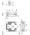
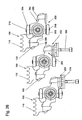
- Fig. 2 is a longitudinal view of two assembled guide rail elements 700 with the inclusion of the two flanges 910, 920, which are struck each end face. The frictional connection between the two adjacent flanges 910, 920 is then made by a screw 900, which will be discussed in more detail below.
- Fig. 3 shows the connecting element in a three-dimensional view, which is helpful for understanding the structural design. From this figure it can be seen that a projection 930 formed on a contact surface engages in a recess 940 provided on the opposite contact surface of the connected flange.
- the projection 930 has a three-dimensional vertical guide which is widened with a horizontal projecting nose.
- the yoke surface of the flange has two further centering means 931 and 941, which also behave as described above, ie they also exercise a guiding and centering function.
- Both the projection 930, 941 and the recesses 940, 931 have on all sides a tapered contour, whereby the assembly is simplified and at the same time an optimal centering function is achieved.
- the respective connecting element 910 or 920 is connected to the respective guide rail element 700 by screw 950, and this preferably by means of countersunk screws, which do not affect the abutment surface for the axial positioning.
- FIG. 4 shows the front part of the flange 910 according FIG. 3 ,
- the internal passages correspond essentially to the channel-shaped design of each guide rail element (see Fig. 1 and 10 ) over its entire length, ie connecting element 910 and 920 and guide rail element 700 have the same bushings why the following description of the flange can also be transferred to the guide rail element 700.
- the guide arrangement 600 has a guide channel 620 and a drive channel 610.
- the guide channel 620 has on its side facing away from the drive channel 610 a slot-shaped opening 630, through the functional means 350 of the drive chain 10 (see also Fig. 16 ) can be led out of the guide channel 620.
- Fig. 4 are within the flange 910, 920 the guide channel 620 limiting adapter elements 850 releasably inserted. Through these adapter elements 850, a smooth transition between the running surfaces of the flange 910, 920 and the subsequent guide rail elements 700 is ensured. This is accomplished by the fact that tread portions 852 of the adapter elements 850, which are chamfered in opposite directions or tapered in the conveying direction F, reach 850, as can be seen from FIG Fig. 5 evident.
- FIG. 6 and 7 show the structure of the connecting elements 800, which frictionally connect the flanges 910, 920 and the guide rail elements 700 firmly connected to these flanges to a guide rail arrangement 600.
- two 960 screws are used (see Fig. 7 ), which act on both sides of the flanges to be connected in the vertical direction.
- the upper and lower sides of the shaft screw 960 with two Brids 961, 962 in operative connection, wherein the screwing done from above, therefore, the lower Bride 962 a thread for tightening the shaft cover 960 on.
- the two bridges 961, 962 each have a dovetail profile 963, which also detect dovetail portions of the flanges and which act in opposite directions.
- Fig. 8 shows a profile of a guide rail element 700 of an inventive guide rail assembly 600 d.
- the guide rail member 700 defines the guide channel 620 and the drive channel 630.
- the guide channel 620 has a substantially square cross-section, wherein at the corners of the guide channel 620 each two support portions 702 to 709 for tread elements 750 (see FIG. Fig. 15 ) are provided.
- the carrier regions 702 to 709 are designed essentially in the form of T-profiles extending along the conveying path, so that the tread elements 750 of the in Fig. 15 shown type with substantially C-shaped profiles can be releasably pushed onto it.
- a recess 720 extending along the conveying path is provided, into which screw bolts serving for fastening the connecting elements 800 to the guide rail elements 700 are screwed.
- the screw bolts simultaneously stabilize the position of the carrier regions 702 to 709.
- the spatial proximity between the recesses 720 serving to receive the screw bolts and the carrier regions 702 to 709 ensures a particularly precise alignment of the carrier regions 702 to 709 with respect to carrier regions of adjacent connecting elements 800.
- outwardly open channels 740 are arranged. Within these channels can be received externally accessible and extending with its bolt axis in the conveying direction bolts that are used to Attachment of the guide rail elements 700 to each other via the flanges 910, 920. What the fasteners 800 and their attachment is to the description of 6 and 7 directed
- the connecting element according to Fig. 3-7 in conjunction with the guide rail element according to Fig. 8-10 it is merely necessary to ensure that the axial connection between the two is ensured, ie, that the screw connections 950 between the connecting element and the guide rail element are aligned with one another.
- the recesses 720 See Fig. 8
- other possible connections between the two elements come into play, for example, if instead of an axial screw a circumferential anchorage is made, in which case also take into account that the last still the guide rail elements 700 must be connected to each other via the flanges.
- tread elements 750 may be implemented with uniform T-shaped recesses 752 having different wall thicknesses so as to ensure desired guide conditions for the guide rollers of the transport member received in the guide channel 620 FIGS. 14 and 15 is explained.
- the tread segments 852 (See also Fig. 11 ) of the adapter elements 850 are releasably secured to the main body 854 of the adapter elements 850 in order to be able to obtain the desired guidance properties in the area of the adapter elements 850 as well. It can be seen that the tread elements 852 make an acute angle ⁇ (see FIG Fig. 13a ) having in the conveying direction F including treads 853, so as to in Fig. 5 to be able to achieve recognizable opposing chamfering of the running surfaces.
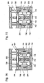
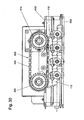
- Fig. 14 shows a sectional view of a conveying device with a received in a rectilinear portion of a guide arrangement according to the invention conveyor member 10 (see also Fig. 16 ), which is the basis here Profile according to a guide rail element Fig. 8-10 equivalent.
- the guide roller 202 of the transport member rests on a tread element 750 pushed onto the carrier region 702 of the guide rail element 700.
- the guide roller 208 of the transport member abuts against a tread element 750 pushed onto the carrier region 704.
- the guide roller 204 rests against a tread element 750 pushed onto the carrier region 708 and the guide roller 206 bears against a tread element 750 pushed onto the carrier region 706.
- the wall thicknesses of the tread elements 750 are selected such that the transport element resting against them with their guide rollers 202 to 208 is guided without play in the guide channel 620 of the guide rail element 700. As a result of the spatial arrangement of the tread elements 750, a friction-friction-free guidance of the transport element in the guide rail element 700 is ensured.
- Fig. 15 shows a sectional view of a conveyor along a plane perpendicular to the conveying direction cutting plane of an arcuate portion of the guide assembly.
- corresponding tread elements 750 are also pushed onto the carrier regions 703, 705, 707 and 709.
- the wall thicknesses of the tread elements 750 are selected in the arcuate regions so that the guide rollers 202, 204, 206 and 208 are received between the carrier regions 702 and 703 or 704 and 705 or 708 and 709 or 706 and 707 with slight play.
- FIGS. 14 and 15 For a better understanding of the guide arrangement and its operation nor a transport organ is shown in three-dimensional representation.
- This transport member which will be described in more detail below, forms an advantageous embodiment.
- an application of the guide arrangement described here with the transport element shown here offers great advantages.
- a coupling of the two is therefore not an indispensable requirement.
- gripper-like functional devices 350 can be fastened to the functional members of the conveying members belonging to the conveying member 10 via connecting devices 310 and pass through the recess 630 in the conveying channel.
- the illustrated guide rail assembly 600 in addition to the illustrated application can also fulfill other functions.
- substantially flat metal sheets are provided on the underside of the chain link 200 (see FIG Fig. 24, 25 ) can be arranged.
- the guide pin 216 (see FIG Fig. 24, 25 ) are suitable.
- These sheets can also be designed so that they are flexible and material behave like a lamellar.
- the application of this product-compliant transport surface can be achieved by pivoting the entire guide rail assembly 600 through 180 ° so that the chain drive (See Fig. 30 , Pos.
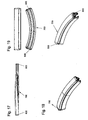
- the guide rail elements can be designed to be twisted with respect to a torsion axis running parallel to the conveying direction, wherein connecting elements 800 can be arranged on both end faces of the guide rail elements 700.
- the guide rail elements 700 may be circular arc-shaped in a vertical arc axis, with those provided by the functional device 350 (See FIG Fig. 16 ) 630 (See Fig. 8 ) may face the bow axis.
- This transport member is particularly well suited to be used in conjunction with the guide member described above.
- the transport members shown in various figures comprises functional members in the form of first chain links 100 and second chain links 200.
- Each of the first chain links 100 has a comb-shaped coupling region 110 for coupling the transport member to a drive chain 530 (cf. Fig. 30 ) on.
- each of the second chain links 200 has a total of four guide rollers 202, 204, 206, 208, wherein the guide rollers 206 and 208 are rotatably mounted with respect to a first common roller axis and the guide rollers 202, 204 are rotatably mounted with respect to a second common roller axis.
- the first and second roller axes are perpendicular to each other and arranged in a plane.
- Each of the first links 100 is disposed between two second links 200.
- each of the first chain links 100 is connected rigidly with one of the second chain links 200 on the one hand to form a functional arrangement and on the other hand with the other of the second chain links 200 to form a joint arrangement.
- a screw bolt 300 is inserted, which passes through a bore in a connecting region 250 of the second chain link 200 and is screwed into a connecting region 150 of the first chain link 100.
- a blind hole 152 is formed in the first link 100, in which a threaded insert 310 is inserted, which is penetrated by the bolt 300.
- the blind hole 152 is according to Fig.
- the bolt head 302 lies on the side of the second chain link 200 facing away from the coupling region 110 with the interposition of a connecting device 310 on.
- the connecting device 310 serves for the coupling of functional devices, such as gripper or staple elements, or lamellae to the transport member.
- the connecting portion 250 of the first chain link 100 has a projection 256 and a groove-shaped recess 252, into which a bulge 254 of the projection 256 protrudes, while the connecting portion 150 of the first chain link 100 complementary thereto with an engaging into the channel-shaped recess 252 Projection 152 and a projection 256 receiving indentation 156 is executed, wherein the projection 152 also has a recess 254 receiving indentation, so that by nesting the connecting portion 150 of the first chain link 100 in the connecting portion 250 of the second chain link 200 is a positive connection between the first chain link 100 and the second chain link 200, the bolts passing through the projection 256 and inserted into the blind hole 152 formed between the recess 156 and the coupling region 110 of the first chain link 100 (see FIG Fig. 22 ) can be locked.
- the projection 256 also has a nose-like engagement region 258, which
- the coupling region 110 is comb-like with comb teeth extending transversely to the conveying direction and approximately parallel to the axis of the bolt 300, a space is formed between the comb teeth into which the chain pins of the drive chain 530 (see FIG Fig. 30 ) intervene.
- the guide rollers 202, 204, 206, 208 are rotatably mounted on guide pins 212, 214, 216, 218, so that between the guide pins 212, 214, 216, 218 still space for producing a hinged connection between the first chain links 100 and second chain links 200 to Available.
- the joint arrangement produced by the articulated connection between the first chain links 100 and the second chain links 200 will be described with reference to FIGS Fig. 14-17 explained.
- the first chain link 100 has an insertion region 120 that extends transversely to the pin axis in the conveying direction and that engages in a receiving region 220 formed between the guide pins 212, 214, 216, 218 of the first chain link 100 is included.
- the insertion region 120 is embodied in the manner of a circular disc segment, while the receiving region 220 is designed in the form of a circular disc segment, so that a guide for pivotal movement of the first chain link 100 relative to the second chain link 200 about a pivot axis formed by the second roller axis is formed by the boundary surfaces of the insertion region 120 and the receiving region 220 is.
- the articulated connection between the first chain link 100 and the second chain link 200 has a ball segment 124 received in the insertion region 120, a spherical shell segment-shaped sliding element 122 made of a plastic material having a low coefficient of sliding friction being arranged between the ball segment 124 and the outer region of the insertion region 120. Ball segment 124 and spherical shell segment 122 pass through the insertion region 120.
- the insertion region 120 accommodating the spherical segment 124 is rotatably mounted on the spherical segment 124 via the spherical shell segment 122 so that the first chain link 100 engages with the insertion region 120 after insertion of the insertion region 120 into the receiving region 220
- Axis of the connecting bolt 126 and a perpendicular thereto and parallel to the bolt 130 extending axis 128 is pivotally mounted, wherein the pivoting movement with respect to the pivot axis 128 is determined by the width of the receiving portion 220 in the direction determined by the axis of the bolt 126 direction. If necessary, this width can be increased.
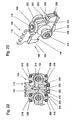
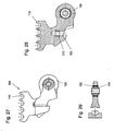
- Fig. 26 shows a mounted conveying member, which consists of a number of transport organs, each consisting of a first and a second chain link, this figure is explained in more detail below.
- the first chain link 100 is shown in detail.
- the insertion region 120 of the first chain link 100 is according to FIGS. 28 and 29 by partially sheathing the ball segment 124 with a low-friction plastic material to form a spherical shell segment 122, whereby the ball segment 124 thus formed can be overmolded with a plastic, in particular a fiber-reinforced plastic, to form the insertion region 120.
- the spherical shell segment 122 is formed in one piece, may also be two or more parts.
- the connecting region 150 and the coupling region 110 can be formed at the same time, wherein also it is thought to insert the threaded insert 310 in the blind hole 152 during the injection process.
- Fig. 26 can conveyors resp. Transport organs are mounted by first joint assemblies of first chain links 100 and second chain links 200 pre-assembled, then put together in the connecting portions 150 and 250 and then locked by means of the screw 300.
- conveyor chains 500 can be conveyed along a conveying path formed by a guide rail arrangement 600, wherein the conveying member is accommodated within the guide rail 600 and guided by means of the guide rollers 202, 204, 206, 208 on corresponding running surfaces of the guide rail 600.
- the coupling regions 110 are accommodated in a drive space 610 of the guide rails 600 and mesh in drive sections of the guide rail arrangement 600 a drive chain 530 of a drive device 500, which rotates two chain wheels 510 and 520.
- For coupling the drive device 530 only a recess in a boundary surface of the drive space 610 has to be produced, through which the drive chain 530 can reach the region of the coupling regions 110.
- the invention is not limited to the embodiment explained with reference to the drawing. Rather, od also differently configured guide rail arrangements with three or less guide rollers, guide pins. Like. Intended. Furthermore, the coupling regions of the transport organs can be configured differently. Also, the gimbal connection of individual links to the formation of joint arrangements is intended.
- the sequentially arranged functional units then have means or connecting elements for a detachable, or due to adhesion-related releasable, and / or a non-detachable connection.
- the functional units can be connected to each other differently at least to form a transport member. In most cases, one will opt for a detachable connection, such as a screw connection. However, it is also possible to provide a frictional merger, which then behaves as a releasable connection when needed.
- the individual conveyor units can be firmly connected to each other by a non-detachable connection, for example via a welded connection.
- a non-detachable connection for example via a welded connection.
- installed additional units between the individual functional units and / or chain links resp. may be arranged, which fulfill a certain functionality. This functionality is broad: it can for example improve the operation of the functional units, or it can be provided aggregates, which are related to the transport of the printed products or the conveyed goods.
Landscapes
- Engineering & Computer Science (AREA)
- Mechanical Engineering (AREA)
- Framework For Endless Conveyors (AREA)
- Chain Conveyers (AREA)
- Feeding Of Articles By Means Other Than Belts Or Rollers (AREA)
Description
Die Erfindung betrifft eine Führungsanordnung zum Führen der Bewegung eines zum Fördern von Produkten gemäss Oberbegriff des Anspruchs 1.The invention relates to a guide arrangement for guiding the movement of a product for conveying products according to the preamble of
Die
Fördervorrichtungen mit einer mit Hilfe einer geeigneten Führungsanordnung längs einer vorzugsweise endlos umlaufenden Förderstrecke geführten Förderkette werden zum Transport von Druckprodukten zwischen einzelnen Verarbeitungsstationen, wie etwa Einsteckmaschinen, Adressiervorrichtungen, Klebeapparaten, etc., benutzt. Dabei werden die Druckprodukte üblicherweise von an den Kettengliedern montierten Greifern bzw. Klammern gehalten und gegebenenfalls an den Verarbeitungsstationen aus den Greifern freigegeben. Zur Gewährleistung eines kontinuierlichen Betriebs ist die Förderkette üblicherweise endlos umlaufend längs der durch die Führungsanordnung festgelegten Förderstrecke antreibbar. Die Förderstrecke weist üblicherweise gerade und bogenförmige Abschnitte auf, wobei die bogenförmigen Abschnitte innerhalb einer Horizontalebene, einer Vertikalebene oder einer schräg nach oben oder unten verlaufenden Ebene angeordnet sein können. Entsprechend muss auch die Führungsanordnung geradlinige sowie bogenförmige Führungselemente aufweisen, durch welche die Bögen der Förderstrecke bestimmt werden.Conveying devices with a conveyor chain guided by means of a suitable guide arrangement along a preferably endlessly circulating conveying path are used for transporting printed products between individual processing stations, such as inserting machines, addressing devices, gluing machines, etc. In this case, the printed products are usually held by grippers or clamps mounted on the chain links and, if appropriate, released from the grippers at the processing stations. To ensure continuous operation, the conveyor chain is usually driven endlessly circumferentially along the conveying path defined by the guide arrangement. The conveyor line usually has straight and arcuate sections, wherein the arcuate sections may be arranged within a horizontal plane, a vertical plane or an obliquely upwardly or downwardly extending plane. Correspondingly, the guide arrangement must also have rectilinear and arc-shaped guide elements, by means of which the arcs of the conveying path are determined.
Die Förderstrecke kann sich über eine Länge von 100 m oder mehr erstrecken und dabei einen gesamten Produktionsraum in horizontaler und vertikaler Richtung durchlaufen. Daher kann die zur Festlegung der Förderstrecke dienende Führungsanordnung nicht einstückig gefertigt werden, sondern muss aus einzelnen mit Hilfe von geeigneten Verbindungsanordnungen miteinander verbundenen Führungselementen zusammengesetzt werden. Entsprechende Führungsanordnungen sind bspw. in der
Bei der Montage der Führungsanordnungen muss darauf geachtet werden, dass die zur Führung der Bewegung der Förderkette dienenden Führungsflächen der Führungselemente bündig und ohne Abstufungen ineinander übergehen, um einen geräusch- und verschleissarmen Betrieb der die Führungsanordnung und die Förderkette aufweisenden Fördervorrichtung zu gewährleisten. In vielen Fällen machen diese Anforderungen an die Übergänge zwischen den Führungselementen eine Nachbearbeitung dieser Übergänge erforderlich, wie etwa eine Schleifbearbeitung. Aber auch nach einer solchen zusätzlichen Bearbeitung wird in einigen Fällen noch ein unruhiger Lauf der Förderkette längs der Führungsanordnung beobachtet.During assembly of the guide arrangements, care must be taken that the guide surfaces of the guide elements serving to guide the movement of the conveyor chain are flush with one another and without gradations, in order to ensure low-noise and low-wear operation of the conveyor device having the guide arrangement and the conveyor chain. In many cases, these transitions between the guide elements require reworking of these transitions, such as grinding. But even after such additional processing in some cases, a restless run of the conveyor chain along the guide arrangement is observed.
Angesichts dieser Probleme im Stand der Technik liegt der Erfindung die Aufgabe zugrunde, eine Führungsanordnung zum Führen der Bewegung einer zum Fördern von Druckprodukten ausgelegten Förderkette anzugeben, welche unter Gewährleistung eines geräuschund verschleissarmen Betriebs einfach montierbar ist, sowie eine Fördervorrichtung mit einer derartigen Führungsanordnung bereitzustellen.In view of these problems in the prior art, the present invention seeks to provide a guide assembly for guiding the movement of a designed for conveying printed products conveyor chain, which is easy to install while ensuring low-noise and low-wear operation, and to provide a conveyor with such a guide arrangement.
Hier will die Erfindung Abhilfe schaffen. Der Erfindung, wie sie in den Ansprüchen gekennzeichnet ist, liegt die Aufgabe zugrunde, eine Führungsanordnung vorzuschlagen, welche die Nachteile der zum Stand der Technik gehörenden Anordnungen zu beheben vermag. Aufgabe der Erfindung ist darüber hinaus eine Führungsanordnung bereitzustellen, welche ohne Weiteres auch mit zum Stand der Technik gehörenden Transportsorganen betrieben werden kann. Die erfindungsgemässe Führungsanordnung ist demnach aufgabengemäss nicht nur für ein spezielles zugeschnittenes Transportorgan ausgelegt. Eine weitere Aufgabe der Erfindung ist es, einen geräuscharmen und verschleissminierten Betrieb zu gewährleisten.The invention aims to remedy this situation. The invention, as characterized in the claims, the object is to propose a guide arrangement, which is able to overcome the disadvantages of belonging to the prior art arrangements. The object of the invention is also to provide a guide arrangement, which can be operated without further including with belonging to the prior art transport organs. The inventive guide arrangement is therefore designed according to the task not only for a special tailored transport organ. Another task The invention is to ensure a low-noise and wear-minimized operation.
Bei der erfindungsgemässen Führungsanordnung werden demnach auf den quer, insbesondere etwa senkrecht, zur Förderstrecke verlaufenden Stirnflächen der einzelnen Führungselemente Verbindungselemente Kraftschlüssig festgelegt, welche anschliessend durch formschlüssigen Eingriff lagerichtig miteinander verbunden werden können. Dabei kann die Festlegung der Verbindungselemente an den Führungselementen werksseitig erfolgen, so dass die aus Führungselement und Verbindungselement bestehenden Baugruppen unter Rückgriff auf Standardbauelemente, wie etwa geradlinig verlaufende Führungselemente, bogenförmig verlaufende Führungselemente und Verbindungselemente vorkonfektioniert werden können. Dabei kann bei der werksseitigen Vorkonfektionierung ein glatter Übergang von Führungselement auf Verbindungselement sichergestellt werden. Am Montageort können die so vorkonfektionierten Baugruppen im Bereich einander zugewandter stimflächenseitiger, d. h., ebenfalls etwa senkrecht zur Förderstrecke verlaufender, Kontaktflächen der Verbindungselemente formschlüssig miteinander verbunden werden, wobei durch die formschlüssige Verbindung der den entsprechenden Führungselementen abgewandten Kontaktflächen eine Selbstzentrierung der vorkonfektionierten Baugruppen zueinander erfolgt, mit der ein glatter Übergang zwischen den zur Führung der Förderkette dienenden Führungsflächen der einzelnen Baugruppen sichergestellt wird. Dabei wurde im Rahmen der Erfindung im besonderen erkannt, dass der durch die Bereitstellung von Führungselementen und Verbindungselementen verursachte Mehraufwand im Hinblick auf die damit erreichte Montagevereinfachung am Montageort ohne weiteres in Kauf genommen werden kann, weil diese Montagevereinfachung eine deutliche Verkürzung der Montagezeit mit sich bringt, welche auch durch die werksseitige Vorkonfektionierung der Baugruppen nicht kompensiert wird.In the guide arrangement according to the invention, therefore, connecting elements are positively fixed to the transversely, in particular approximately perpendicularly, the conveyor track extending end faces of the individual guide elements, which can then be connected in the correct position by positive engagement with each other. In this case, the determination of the connecting elements on the guide elements can be made at the factory, so that the components consisting of guide element and connecting elements can be prefabricated by resorting to standard components, such as linearly extending guide elements, arcuate guide elements and connecting elements. In this case, a smooth transition from guide element to connecting element can be ensured in the factory pre-assembly. At the installation site, the prefabricated assemblies in the area facing each other surface side, d. h., Also approximately perpendicular to the conveyor line extending contact surfaces of the connecting elements are positively connected with each other, wherein the positive connection of the corresponding guide elements facing away from contact surfaces self-centering of the prefabricated assemblies to each other, with a smooth transition between serving to guide the conveyor chain guide surfaces the individual modules is ensured. In the context of the invention, it has been found in particular that the additional expenditure caused by the provision of guide elements and connecting elements can readily be accepted with regard to the assembly simplification achieved at the installation site because this simplification of the assembly results in a significant reduction of the assembly time. which is not compensated by the factory pre-assembly of the modules.
Der formschlüssige Eingriff einander zugewandter stirnseitiger Kontaktflächen der an den Führungselementen festgelegten Verbindungselemente kann erreicht werden, wenn eine Kontaktfläche mindestens einen Vorsprung und die andere Kontaktfläche mindestens eine den Vorsprung formschlüssig aufnehmende komplementär dazu gebildete Vertiefung und/oder Ausnehmung aufweist. Die Verbindungselemente weisen dabei üblicherweise eine dem Führungselement zugewandte im wesentlichen ebene Begrenzungsfläche sowie eine etwa parallel zu dieser ebenen Begrenzungsfläche verlaufende Kontaktfläche auf, wobei ein Vorsprung der Kontaktfläche sich längs der Förderstrecke etwa in die der dem Führungselement zugewandten Begrenzungsfläche entgegengesetzte Richtung erstreckt, während sich die Vertiefung in Richtung auf die dem Führungselement zugewandte Begrenzungsfläche erstreckt.The positive engagement of mutually facing end-face contact surfaces of the fasteners fixed to the guide elements can be achieved if a contact surface has at least one projection and the other contact surface at least one positive fit receiving the projection complementary thereto formed recess and / or recess. In this case, the connecting elements usually have a substantially flat boundary surface facing the guide element and a contact surface extending approximately parallel to this flat boundary surface, wherein a projection of the contact surface extends approximately along the conveying path into that of the guide element facing boundary surface extends opposite, while the recess extends in the direction of the guide element facing the boundary surface.
Im Hinblick auf die Verminderung der Anzahl von zur Herstellung beliebiger Führungsanordnungen benötigten Bauteilen hat es sich als zweckmässig erwiesen, wenn jede Kontaktfläche mindestens einen Vorsprung und mindestens eine Vertiefung aufweist, derart, dass eine formschlüssige Verbindung im Bereich von zwei einander zugewandten gleichförmigen Kontaktflächen bewirkt werden kann. Dabei sind Vorsprung und Vertiefung der Kontaktfläche vorzugsweise spiegelsymmetrisch bezüglich einer senkrecht zur Förderstrecke verlaufenden Geraden ausgeführt.With regard to the reduction of the number of components required for the production of any guide arrangements, it has proved to be expedient if each contact surface has at least one projection and at least one recess such that a positive connection can be effected in the region of two mutually facing uniform contact surfaces , In this case, projection and recess of the contact surface are preferably mirror-symmetrical with respect to a straight line running perpendicular to the conveyor line.
Mit Blick auf die gewünschte selbstzentrierende formschlüssige Verbindung der Verbindungselemente bzw. der unter Einsatz der Verbindungselemente hergestellten vorkonfektionierten Baugruppen hat es sich als zweckmässig erwiesen, wenn ein Vorsprung in einer senkrecht zur Förderrichtung verlaufenden Schnittebene eine sich in Richtung auf die benachbarte Kontaktfläche bzw. Vertiefung verjüngende Querschnittsfläche aufweist, wobei auch die zur Aufnahme des Vorsprungs gedachte Vertiefung eine sich entsprechend verjüngende Querschnittsfläche aufweisen kann.With a view to the desired self-centering positive connection of the connecting elements or the prefabricated assemblies produced using the connecting elements, it has proved to be expedient if a projection in a sectional plane running perpendicular to the conveying direction has a cross-sectional area tapering in the direction of the adjacent contact surface or depression wherein the recess intended to receive the projection may also have a correspondingly tapering cross-sectional area.
Durch das formschlüssige Ineinandergreifen der Verbindungselemente soll üblicherweise nicht nur ein translatorischer Versatz der daraus hergestellten Baugruppen gegeneinander in einer quer zur Förderrichtung verlaufenden Richtung, sondern auch eine Kippbewegung dieser Baugruppen bezüglich einer parallel zur Förderrichtung verlaufenden Kippachse verhindert werden. In diesem Zusammenhang ist es zweckmässig, wenn mindestens ein Vorsprung und die komplementär dazu ausgeführte Vertiefung in einer sich senkrecht zur Förderrichtung erstreckenden Schnittebene eine einer Drehbewegung um eine parallel zur Förderrichtung verlaufende Drehachse entgegenwirkende Querschnittsfläche aufweist, d. h. wenn diese Querschnittsfläche von einer Kreisscheiben- oder Ringform abweicht.By the positive engagement of the connecting elements should usually not only a translational offset of the assemblies produced therefrom against each other in a direction transverse to the conveying direction, but also a tilting movement of these assemblies are prevented with respect to a parallel to the conveying direction tilting axis. In this context, it is expedient for at least one projection and the complementary recess to have a cross-sectional surface which counteracts a rotational movement about a rotation axis extending parallel to the conveying direction in a sectional plane extending perpendicularly to the conveying direction, ie. H. if this cross-sectional area deviates from a circular disk or ring shape.
Eine Verbesserung der Montagegenauigkeit kann erreicht werden, wenn mindestens eine Kontaktfläche zwei, drei oder mehr Vorsprünge aufweist, die im montierten Zustand in entsprechend komplementär ausgebildeten Vertiefungen bzw. Ausnehmungen der anderen Kontaktfläche formschlüssig aufgenommen sind.An improvement in the mounting accuracy can be achieved if at least one contact surface has two, three or more projections which are positively received in the mounted state in correspondingly complementary recesses or recesses of the other contact surface.
Wenngleich auch vorstellbar ist, dass Führungsanordnungen hinreichender Stabilität bereits durch die formschlüssige Verbindung der Kontaktflächen der Verbindungselemente geschaffen werden können, hat es sich mit Blick auf die Betriebszuverlässigkeit erfindungsgemässer Führungsanordnungen als besonders sinnvoll erwiesen, wenn die Verbindungsanordnung eine zum Koppeln der Verbindungselemente im Bereich der Kontaktflächen dienende, vorzugsweise von aussen zugängliche, Befestigungsanordnung aufweist, mit der die formschlüssige Verbindung der Verbindungselemente gesichert werden kann.Although it is also conceivable that guide arrangements of sufficient stability can already be created by the positive connection of the contact surfaces of the connecting elements, it has proven to be particularly useful in view of the operational reliability of inventive guide arrangements when the connection arrangement serving for coupling the connecting elements in the region of the contact surfaces , Preferably accessible from the outside, mounting arrangement, with which the positive connection of the connecting elements can be secured.
- Eine derartige Befestigungsanordnung kann besonders einfach in Form eines sich parallel zur Förderstrecke erstreckenden, ein Verbindungselement durchsetzenden und in einem vorzugsweise in das benachbarte Verbindungselement eingesetzten Gewinde, wie etwa einer von aussen zugängliche Gewindemutter, aufgenommenen Befestigungsbolzens, insbes. Schraubbolzens, verwirklicht sein. Im Hinblick auf die Vermeidung vorspringender Teile im Bereich der Führungsanordnung hat es sich als zweckmässig erwiesen, wenn der Befestigungsbolzen in einer in einer äusseren Begrenzungsfläche des Führungselements gebildeten und sich längs der Förderstrecke erstreckenden nutförmigen Ausnehmung aufgenommen ist, in der der Bolzenkopf beispielsweise für einen Inbusschlüssel zugänglich ist. Die Gewindemutter kann gegen Verdrehung gesichert in einer entsprechenden Aufnahme in einem der Verbindungselemente aufgenommen sein.Such a fastening arrangement can be realized in a particularly simple manner in the form of a fastening bolt extending in parallel to the conveying path, passing through a connecting element and inserted in a thread which is preferably inserted into the adjacent connecting element, such as a threaded nut accessible from the outside, in particular a screw bolt. With regard to the avoidance of protruding parts in the region of the guide arrangement, it has proved to be expedient if the fastening bolt is received in a groove-shaped recess formed in an outer boundary surface of the guide element and extending along the conveying path, in which the bolt head is accessible, for example, for an Allen wrench is. The threaded nut can be secured against rotation in a corresponding receptacle in one of the connecting elements.
Bei der beschriebenen Befestigungsanordnung muss der Befestigungsbolzen innerhalb der nutförmigen Ausnehmung in Richtung der Förderstrecke in die Gewindemutter eingeschraubt werden. Das kann bei der Montage Probleme verursachen. In einigen Fällen hat es sich montagetechnisch als günstig erwiesen, wenn die zum Sichern der formschlüssigen Verbindung dienende Befestigungsanordnung zwei in benachbarte und im montierten Zustand mit ihren Kontaktflächen aneinander anliegende Verbindungselemente einsetzbare und darin arretierbare, sich jeweils quer, insbes. senkrecht, zur Förderstrecke und besonders bevorzugt parallel zueinander erstreckende Befestigungsbolzen mit einem ausserhalb der Verbindungselemente freiliegenden Kopplungskopf aufweist, die über ein bezüglich beiden Kopplungselementen arretierbares Arretierungselement miteinander verbunden sind. Bei dieser Befestigungsanordnung werden die Befestigungsbolzen in entsprechende Ausnehmungen in die Verbindungselemente eingesteckt, wobei die Arretierung der Befestigungsbolzen in den entsprechenden Ausnehmungen der Verbindungselemente mit Hilfe einer Schnappverbindung erfolgen kann. Danach wird das Arretierungselement auf ausserhalb der Verbindungselemente freiliegende Bereiche der Befestigungsbolzen aufgeschoben, um so die formschlüssige Verbindung der Verbindungselemente zu sichern. Insgesamt ist die gerade beschriebene Befestigungsanordnung nach dem Vorbild eines Kettenschlosses ausgeführt, wobei alle Bestandteile, einschl. dem Arretierungselement, in einer äusseren Begrenzungsfläche der Befestigungselemente versenkt angeordnet sein können, um so vorspringende Teile der Führungsanordnung zu vermeiden.In the described mounting arrangement of the fastening bolt must be screwed within the groove-shaped recess in the direction of the conveying path in the threaded nut. This can cause problems during installation. In some cases, it has proven to be mounting technology favorable when the serving to secure the positive connection fastening arrangement two in adjacent and assembled state with their contact surfaces abutting fasteners insertable and lockable, each transverse, esp. Vertically, to the conveyor line and especially Preferably, parallel to each other extending mounting bolts having a coupling head exposed outside of the connecting elements, which are connected to one another via a locking element can be locked with respect to two coupling elements. In this fastening arrangement, the fastening bolts are inserted into corresponding recesses in the connecting elements, wherein the locking of the fastening bolts in the corresponding recesses of the connecting elements by means of a snap connection can be made. Thereafter, the locking element is pushed onto outside of the connecting elements exposed areas of the fastening bolts, so as to secure the positive connection of the connecting elements. Overall, the fastening arrangement just described is carried out on the model of a chain lock, wherein all components, including the locking element, can be recessed in an outer boundary surface of the fastening elements, so as to avoid projecting parts of the guide assembly.
Bei der gerade beschriebenen Montage ist wiederum das Aufschieben des Arretierungselements in einer parallel zur Förderrichtung verlaufenden Richtung erforderlich. Bei einer alternativen Montageform können die Befestigungsbolzen zunächst über das bspw. nach Art eines U-Bügels gebildete Arretierungselement miteinander verbunden und danach in die Aufnahmen der Verbindungselemente eingesetzt werden. Das kann bei schwierigen Montagebedingungen von Vorteil sein.In the assembly just described, in turn, the sliding of the locking element in a direction parallel to the conveying direction is required. In an alternative form of installation, the fastening bolts can first be connected to one another via the locking element formed, for example, in the manner of a U-bracket, and then inserted into the receptacles of the connecting elements. This can be advantageous in difficult installation conditions.
Im Hinblick auf die Bereitstellung einer zufriedenstellenden Quersteifigkeit der formschlüssigen Verbindung der Verbindungselemente hat es sich als zweckmässig erwiesen, wenn mindestens ein Vorsprung in einer senkrecht zur Förderstrecke verlaufenden Schnittebene einen winkelförmigen Querschnitt aufweist, wobei die dann vorhandenen Schenkel des Vorsprungs einen rechten Winkel miteinander einschliessen können, um so eine besonders hohe Quersteifigkeit in senkrecht zueinander verlaufenden Richtungen bereitzustellen.With regard to the provision of a satisfactory transverse rigidity of the positive connection of the connecting elements, it has proven to be expedient if at least one projection has an angular cross-section in a sectional plane running perpendicular to the conveying path, wherein the then existing legs of the projection can enclose a right angle with each other, so as to provide a particularly high transverse rigidity in mutually perpendicular directions.
Bei einer besonders bevorzugten Ausführungsform der Erfindung dienen die Führungselemente der Führungsanordnung nicht nur der Führung des Förderorgans längs der Förderstrecke, sondern auch dem Schutz des Förderorgans vor Verschmutzungen und mechanischen Belastungen. In diesem Fall begrenzen die Führungselemente und die Verbindungselemente einen sich längs der Förderstrecke erstreckenden, zur Aufnahme des Förderorgans ausgelegten und einseitig offenen Führungskanal. Führungselemente und Verbindungselemente sind bei dieser Ausführungsform der Erfindung in einer sich senkrecht zur Förderstrecke erstreckenden Schnittebene im wesentlichen C-förmig ausgeführt, wobei die sich durchgehend längs der Förderstrecke erstreckende Öffnung des Führungskanals dazu dient, den Durchtritt von an dem Förderorgan festgelegten Funktionseinrichtungen, wie etwa Klammern bzw. Greifern zum Erfassen von Druckprodukten zu ermöglichen.In a particularly preferred embodiment of the invention, the guide elements of the guide arrangement serve not only the leadership of the conveying member along the conveying path, but also the protection of the conveying member from contamination and mechanical loads. In this case, the guide elements and the connecting elements delimit a guide channel extending along the conveying path and designed to receive the conveying member and open on one side. Guide elements and connecting elements are designed in this embodiment of the invention in a direction perpendicular to the conveying section cutting plane substantially C-shaped, wherein the continuously along the conveying path extending opening of the guide channel serves to the passage of defined on the conveying member functional means, such as brackets or grippers to capture printed products.
Im Sinne einer Vermeidung von Vorsprüngen im Bereich der Führungsanordnung, welche Schmutzablagerungen begünstigen, eine Verletzungsgefahr für Bediener und eine Beschädigungsgefahr für längs der Förderstrecke transportierte Druckprodukte bilden können, hat es sich als zweckmässig erwiesen, wenn Führungselemente und Verbindungselemente etwa gleiche Querschnittsflächen in einer senkrecht zur Förderstrecke verlaufenden Schnittebene aufweisen und die parallel zur Förderstrecke verlaufenden äusseren Begrenzungsflächen von Führungselementen und Verbindungselementen nach Verbinden der Führungselemente mit Hilfe der Verbindungselemente miteinander fluchten.In order to avoid projections in the guide arrangement, which favor dirt deposits, a risk of injury to operators and a risk of damage for along the conveyor line transported printed products can form, it has proved to be useful if guide elements and fasteners approximately the same cross-sectional areas in a direction perpendicular to the conveyor line Have extending cutting plane and aligned parallel to the conveyor line extending outer boundary surfaces of guide elements and connecting elements after connecting the guide elements by means of the connecting elements with each other.
Beim Betrieb von Fördervorrichtungen zum Fördern von Druckprodukten, die zum Fördern der Druckprodukte längs einzelner Verarbeitungsstationen dienen, muss eine genaue Positionierung der Druckprodukte sichergestellt werden, um so eine optimale Verarbeitung der Druckprodukte in den Verarbeitungsstationen sicherzustellen. Im Hinblick auf diese besonderen Anforderungen an Fördervorrichtungen für Druckprodukte wird gemäss einem weiteren Gesichtspunkt der Erfindung eine Führungsanordnung zum Führen der Bewegung eines zum Fördern von Druckprodukten ausgelegten Förderorgans, das aus einer Anzahl Transportorgane besteht, längs einer vorzugsweise endlos umlaufenden Förderstrecke mit einer Mehrzahl von einen sich längs der Förderstrecke erstreckenden, zur Aufnahme der Förderkette ausgelegten und einseitig offenen Führungskanal begrenzenden Führungselementen bereitgestellt, die im wesentlichen dadurch gekennzeichnet ist, dass an jedem Führungselement innerhalb des Führungskanals vier oder mehr mit vier oder mehr an einzelnen Kettengliedern des Transportorgans angeordneten Führungseinrichtungen, insbes. Führungsrollen, zusammenwirkende Führungsflächen angeordnet sind, die sich längs der Förderstrecke erstrecken. Gemäss diesem Gesichtspunkt der Erfindung mit einer Führungsanordnung für Förderketten, deren Kettenglieder vier oder mehr Führungseinrichtungen aufweisen, wird für jede einzelne Führungseinrichtung eine eigene Führungsfläche bereitgestellt, um so die Verkippung des Transportorgans bezüglich der Führungsanordnung besonders zuverlässig vermeiden zu helfen. Selbstverständlich können auch die entsprechend ausgeführten Führungselemente mit Hilfe der vorstehend beschriebenen Verbindungselemente formschlüssig miteinander verbunden sein, so dass die besonders verkippungssichere Führung des Transportorgans unter gleichzeitiger Vermeidung eines übermässigen Montageaufwands bereitgestellt werden kann.In the operation of conveyors for conveying printed products which serve to convey the printed products along individual processing stations, accurate positioning of the printed products must be ensured so as to ensure optimum processing of the printed products in the processing stations. In view of these particular requirements for conveyors for printed products is according to a further aspect of the invention, a guide assembly for guiding the movement of a designed for conveying printed products conveying member, which consists of a number of transport organs, along a preferably endless circulating conveyor line with a plurality of a Provided along the conveying path, designed for receiving the conveyor chain and open on one side guide channel limiting guide elements, which is characterized essentially in that four or more with four or more arranged on individual chain links of the transport member guide means, esp. Guide rollers on each guide element within the guide channel , co-operating guide surfaces are arranged, which extend along the conveying path. According to this aspect of the invention with a guide arrangement for conveyor chains whose chain links have four or more guide means, a separate guide surface is provided for each guide means so as to help avoid the tilting of the transport member with respect to the guide arrangement particularly reliable. Of course, the correspondingly executed guide elements with the aid of the above-described connecting elements can be positively connected to each other, so that the particularly tamper-proof guide of the transport member can be provided while avoiding excessive installation work.
Im Hinblick auf die Vermeidung einer Verkippung des Transportorgans bezüglich der Führungsanordnung hat es sich als sinnvoll erwiesen, wenn eine zweite Führungsfläche der Führungselemente einer Schwenkbewegung des Transportorgans zusammenwirkend mit einer daran anliegenden zweiten Führungseinrichtung des Transportorgans bezüglich einer parallel zur Förderstrecke und parallel zu einer ersten Führungsfläche mit einer daran anliegenden ersten Führungseinrichtung verlaufenden Schwenkachse in einer ersten Schwenkrichtung entgegenwirkend, quer, insbes. etwa senkrecht, zu der ersten Führungsfläche verläuft. Demnach sind die erste und die zweite Führungsfläche in vorzugsweise einen rechten Winkel miteinander einschliessenden Ebenen angeordnet, so dass für entsprechende Führungseinrichtungen des Transportorgans Abstützflächen in zwei quer, insbesondere etwa senkrecht, zueinander verlaufenden Abstützrichtungen bereitgestellt sind.With regard to avoiding a tilting of the transport member with respect to the guide arrangement, it has proven to be useful if a second guide surface of the guide elements of a pivoting movement of the transport member cooperating with a second guide means of the transport member with respect to a parallel to the conveyor line and parallel to a first guide surface a pivot axis extending therefrom in a first pivoting direction counteracts, transversely, in particular approximately perpendicular, to the first guide surface in a first pivoting direction. Accordingly, the first and the second guide surface are preferably arranged at a right angle to each other enclosing planes, so that for corresponding guide means of the transport member support surfaces in two transverse, in particular approximately perpendicular, mutually extending support directions are provided.
Eine weitere Verbesserung der Verkippungssicherung der Führungsanordnung kann erreicht werden, wenn eine vorzugsweise etwa parallel zur zweiten Führungsfläche verlaufende dritte Führungsfläche zusammenwirkend mit einer daran anliegenden dritten Führungseinrichtung des Transportorgans einer Schwenkbewegung bezüglich der Schwenkachse in der ersten Schwenkrichtung entgegenwirkt. Dabei ist die dritte Führungsfläche zur Bereitstellung einer spielfreien Führung des Transportorgans zweckmässigerweise in einer senkrecht dazu verlaufenden Richtung derart von der zweiten Führungsfläche beabstandet, dass das Transportorgan mit den an der zweiten Führungsfläche anliegenden zweiten Führungseinrichtungen und den an der dritten Führungsfläche anliegenden dritten Führungseinrichtungen spielfrei bezüglich einer senkrecht zu der zweiten und/oder dritten Führungsfläche verlaufenden Richtung zwischen diesen Führungsflächen geführt ist. Durch Bereitstellung von zwei vorzugsweise etwa parallel zueinander verlaufenden Führungsflächen kann eine spielfreie und gleichzeitig reibungsfreie Führung unter Verwendung von Führungseinrichtungen in Form von bezüglich vorgegebenen Rollenachsen drehbaren Führungsrollen erfolgen. Dabei kann die zweite Führungsrolle in einer senkrecht zur ersten Führungsfläche verlaufenden Richtung von der dritten Führungsrolle beabstandet sein. Mit den bislang beschriebenen drei Führungsflächen wird einer Verkippung des Transportorgans bezüglich der Schwenkachse in einer ersten Schwenkrichtung entgegengewirkt. Eine besonders genaue Führung des Transportorgans längs der Förderstrecke kann erreicht werden, wenn eine vierte Führungsfläche zusammenwirkend mit einer vierten daran anliegenden Führungseinrichtung des Transportorgans einer Schwenkbewegung des Transportorgans bezüglich der Schwenkachse in einer der ersten Schwenkrichtung entgegengesetzten zweiten Schwenkrichtung entgegenwirkt und quer, insbesondere etwa senkrecht, zur zweiten Führungsfläche und vorzugsweise etwa parallel zur ersten Führungsfläche verläuft. Dadurch wird einem Verschwenken bzw. Verkippen des Transportorgans bezüglich einer parallel zur Förderstrecke verlaufenden Schwenk- bzw. Kippachse vollständig entgegengewirkt.A further improvement in the anti-tilting of the guide arrangement can be achieved if a third guide surface extending approximately parallel to the second guide surface cooperatively counteracts a third guide device of the conveyor member with a pivoting movement relative to the pivot axis in the first pivoting direction. In this case, the third guide surface for providing a play-free guidance of the transport member is expediently spaced in a direction perpendicular thereto from the second guide surface, that the transport member with the voltage applied to the second guide surface second guide means and the third guide surface adjacent third guide means play-free with respect to a is guided perpendicular to the second and / or third guide surface extending direction between these guide surfaces. By providing two preferably approximately mutually parallel guide surfaces a play-free and at the same time frictionless guidance can be carried out using guide means in the form of rotatable with respect to predetermined roller axes guide rollers. In this case, the second guide roller may be spaced from the third guide roller in a direction perpendicular to the first guide surface direction. With the three guide surfaces described so far a tilting of the transport member with respect to the pivot axis in a first pivoting direction is counteracted. A particularly precise guidance of the transport member along the conveying path can be achieved if a fourth guide surface cooperates with a fourth guide device of the transport member abutting the pivoting movement of the transport member with respect to the pivot axis in a second opposite direction of the first pivoting direction Counteracts pivoting direction and transverse, in particular approximately perpendicular, to the second guide surface and preferably runs approximately parallel to the first guide surface. This completely counteracts any pivoting or tilting of the transport member with respect to a pivoting or tilting axis extending parallel to the conveying path.
Im Sinne einer spielfreien Führung des Transportorgans innerhalb der Führungsanordnung hat es sich als sinnvoll erwiesen, wenn die vierte Führungsfläche in einer senkrecht dazu verlaufenden Richtung derart von der ersten Führungsfläche beabstandet ist, dass das Transportorgan mit den an der vierten Führungsfläche anliegenden vierten Führungseinrichtungen und den an der ersten Führungsfläche anliegenden ersten Führungseinrichtungen spielfrei bezüglich einer senkrecht zu der ersten und/oder vierten Führungsfläche verlaufenden Richtung geführt ist. Mithin wird auch hier eine spielfreie Führung bezüglich Verschiebungen in einer senkrecht zu der ersten und vierten Führungsfläche verlaufenden Richtung unter Verwendung von Führungseinrichtungen in Form von Führungsrollen unter Vermeidung einer Gleitreibung von Führungsrollen an einer der Führungsflächen ermöglicht, wobei die erste Führungsfläche in einer senkrecht zur zweiten Führungsfläche verlaufenden Richtung von der vierten Führungsfläche beabstandet sein kann.In the sense of a play-free guidance of the transport member within the guide assembly, it has proven to be useful if the fourth guide surface is spaced in a direction perpendicular thereto in such a direction from the first guide surface, that the transport member with the voltage applied to the fourth guide surface fourth guide means and the the first guide surface adjacent first guide means is guided without play with respect to a direction perpendicular to the first and / or fourth guide surface extending direction. Thus, a play-free guidance with respect to displacements in a direction perpendicular to the first and fourth guide surface direction using guide means in the form of guide rollers while avoiding a sliding friction of guide rollers on one of the guide surfaces is also made possible, wherein the first guide surface in a direction perpendicular to the second guide surface extending direction may be spaced from the fourth guide surface.
Im Sinne eines besonders kompakten Aufbaus erfindungsgemässer Führungsanordnungen in einer senkrecht zur Förderstrecke verlaufenden Schnittebene hat es sich als sinnvoll erwiesen, wenn die Schnittlinien einer senkrecht zur Förderstrecke verlaufenden Schnittebene mit den Führungsflächen auf Geraden liegen, die ein in den Führungskanal eingeschriebenes Viereck, insbes. Rechteck, besonders bevorzugt Quadrat, begrenzen. Selbstverständlich können auch anders geartete Querschnitte, beispielsweise mit Wölbungen versehen, zum Einsatz gelangen.In the sense of a particularly compact construction of guide arrangements according to the invention in a sectional plane running perpendicular to the conveyor line, it has proven to be expedient if the intersection lines of a section plane running perpendicular to the conveyor section lie with the guide surfaces on straight lines which comprise a quadrangle inscribed into the guide channel, esp. particularly preferred square, limit. Of course, other types of cross sections, for example, provided with buckles, are used.
Die gerade beschriebene Anordnung der Führungsflächen ist im Bereich geradlinig verlaufender Abschnitte der Führungsstrecke besonders sinnvoll, weil in diesem Bereich mit den beschriebenen vier Führungsflächen eine spielfreie und gegen Verkippungen gesicherte Führung des Transportorgans erfolgen kann. Im Bereich von bogenförmigen Abschnitten der Förderstrecke muss darauf geachtet werden, dass der in Bogenbereichen auftretende Spurfehler des Transportorgans bzw. der an dem Transportorgan angeordneten Führungselemente nicht zu einem übermässigen Verschleiss führt. In diesem Zusammenhang ist es zweckmässig, wenn die Führungseinrichtungen des Transportorgans mit geringfügigem Spiel zwischen Führungsflächen der Führungsanordnung geführt sind. Eine solche Führung kann sichergestellt werden, wenn in dem Führungskanal eine mit Abstand etwa parallel zur ersten und vorzugsweise etwa koplanar zur vierten Führungsfläche verlaufende fünfte Führungsfläche, eine mit Abstand etwa parallel zur zweiten und vorzugsweise etwa koplanar zur dritten Führungsfläche verlaufende sechste Führungsfläche, eine mit Abstand etwa parallel zur dritten und vorzugsweise etwa koplanar zur zweiten Führungsfläche verlaufende siebte Führungsfläche und/oder eine mit Abstand etwa parallel zur vierten und vorzugsweise etwa koplanar zur ersten Führungsfläche verlaufende achte Führungsfläche bereitgestellt wird.The arrangement of the guide surfaces just described is particularly useful in the region of rectilinear sections of the guide track, because in this area with the four guide surfaces described a play-free and secured against tilting guidance of the transport member can be done. Care must be taken in the region of arcuate sections of the conveying path that the tracking error occurring in the bow regions of the transport member or the guide elements arranged on the transport member does not lead to excessive wear. In this context, it is expedient if the guide means of the transport organ with minor Game are guided between guide surfaces of the guide arrangement. Such a guide can be ensured if in the guide channel a with a distance approximately parallel to the first and preferably coplanar to the fourth guide surface extending fifth guide surface, a distance approximately parallel to the second and preferably approximately coplanar to the third guide surface extending sixth guide surface, a distance is provided approximately parallel to the third and preferably approximately coplanar with the second guide surface extending seventh guide surface and / or a distance approximately parallel to the fourth and preferably approximately coplanar to the first guide surface extending eighth guide surface.
Bei dieser Anordnung von insgesamt acht Führungsflächen innerhalb des Führungsanordnung kann eine erste Führungsrolle des Transportorgans zwischen der ersten und der fünften Führungsfläche, eine zweite Führungsrolle des Transportorgans zwischen der zweiten und der sechsten Führungsfläche, eine dritte Führungsrolle des Transportorgans zwischen der dritten und der siebten Führungsfläche und eine vierte Führungsrolle des Transportorgans zwischen der vierten und der achten Führungsfläche angeordnet sein, wobei sämtliche Führungsrollen mit geringfügigem Spiel zwischen den Führungsflächen angeordnet sein können, um so einen durch Spurfehler verursachten Verschleiss zu minimieren.In this arrangement of a total of eight guide surfaces within the guide assembly, a first guide roller of the transport member between the first and the fifth guide surface, a second guide roller of the transport member between the second and the sixth guide surface, a third guide roller of the transport member between the third and the seventh guide surface and a fourth guide roller of the transport member between the fourth and the eighth guide surface may be arranged, wherein all guide rollers may be arranged with slight play between the guide surfaces, so as to minimize a wear caused by tracking error.
Im Sinne einer geräusch- und verschleissarmen Führung des Transportorgans längs der Förderstrecke der Führungsanordnung hat es sich als sinnvoll erwiesen, wenn den Führungsflächen der Führungselemente Führungsflächen der Verbindungselemente zugeordnet sind, in die die Führungsflächen der Führungselemente übergehen. Diese Führungsflächen der Verbindungselemente sind erfindungsgemäß durch in Ausnehmungen der Verbindungselemente lösbar festlegbare Adapterelemente gebildet. Die Adapterelemente können gleichzeitig Vorsprünge der Verbindungselemente bilden, welche zur formschlüssigen Verbindung der Verbindungselemente beitragen.In terms of noise and low-wear guidance of the transport member along the conveying path of the guide arrangement, it has proven to be useful if the guide surfaces of the guide elements guide surfaces of the connecting elements are assigned, in which pass over the guide surfaces of the guide elements. These guide surfaces of the connecting elements are formed according to the invention by releasably fixable in recesses of the connecting elements adapter elements. The adapter elements can simultaneously form projections of the connecting elements, which contribute to the positive connection of the connecting elements.
In diesem Fall hat es sich als besonders vorteilhaft erwiesen, wenn die Führungsflächen von zwei in im Bereich der Kontaktflächen aneinander anliegenden Verbindungselementen eingesetzten Adapterelementen in einer parallel zu den Kontaktflächen und senkecht zur Förderstrecke verlaufenden Richtung nebeneinander angeordnet sind. Dadurch wird durch zwei aneinanderliegende Adapterelemente gemeinsam ein Führungsflächenabschnitt gebildet. In diesem Führungsflächenabschnitt kann unter Vermeidung übermässiger Anforderungen an die Herstellungstoleranzen eine geräuscharme Bewegung des Transportorgans sichergestellt werden, wenn die nebeneinander liegenden Führungsflächen der Adapter-elemente derart gegenläufig angefast bzw. in Förderrichtung abgeschrägt sind, dass sie eine Mulde in der durch die nebeneinander angeordneten Führungsflächen gebildeten Führungsflächenabschnitt bilden und einen stumpfen Winkel miteinander einschliessen. Eine auf einer angefasten Führungsfläche eines Adapterelements abrollende Führungsrolle geht reibungsarm unter Vermeidung von Absätzen auf die gegenläufig angefaste Führungsfläche des anderen Adapterelements über, um so eine sprungfreie Führung des Transportorgans sicherzustellen.In this case, it has proved to be particularly advantageous if the guide surfaces of two adapter elements inserted in the area of the contact surfaces adjoining one another are arranged next to one another in a direction parallel to the contact surfaces and perpendicular to the conveying path. As a result, a guide surface section is jointly formed by two adjoining adapter elements. In this guide surface portion, while avoiding excessive requirements to the manufacturing tolerances a low-noise movement of the transport member can be ensured if the adjacent guide surfaces of the adapter elements are chamfered in opposite directions or chamfered in the conveying direction that they form a trough in the side by side guide surfaces formed guide surface portion and enclose an obtuse angle with each other , A rolling on a chamfered guide surface of an adapter element guide roller is friction, while avoiding paragraphs on the opposite chamfered guide surface of the other adapter element, so as to ensure a jump-free guidance of the transport member.
An zur Sicherstellung einer geräusch- und/oder verschleissarmen Führung dienende Materialien werden oft andere Anforderungen gestellt als an zur Sicherstellung einer ausreichenden Gesamtstabilität der Führungsanordnung erforderliche Materialien. Daher hat es sich als sinnvoll erwiesen, wenn mindestens eine Führungsfläche durch ein lösbar an einem Trägerbereich eines Führungselements festlegbares Laufflächenelement gebildet ist. Montagetechnisch hat es sich in diesem Zusammenhang als zweckmässig erwiesen, wenn der Trägerbereich in Form eines sich längs der Förderstrecke erstreckenden und in einer senkrecht dazu verlaufenden Schnittebene T-förmigen Stegs gebildet ist und das Laufflächenelement in Form eines auf den T-förmigen Steg aufschiebbaren C-Profils gebildet ist. In diesem Fall kann ein an einem Verbindungselement festgelegtes Adapterelement eine Doppelfunktion erfüllen, wenn es nach Festlegen des Verbindungselements an dem Führungselement einen nach Montage des Laufflächenelements auf dem Trägerbereich einer Verschiebung des Laufflächenelements längs der Förderstrecke entgegenwirkenden Anschlag bildet, wobei das auf den Steg aufgeschobene Laufflächenelement einen sich längs der Förderstrecke über einen Teil der Länge des Verbindungselements erstreckenden stegförmigen Trägeransatz übergreifen kann.Materials that are used to ensure low-noise and / or low-wear guidance often have different requirements than materials required to ensure adequate overall stability of the guidance arrangement. Therefore, it has proven to be useful if at least one guide surface is formed by a releasably fixed to a support portion of a guide element tread element. From an assembly point of view, it has proven to be expedient in this context if the carrier area is formed in the form of a section extending along the conveying path and in a section plane T-shaped extending perpendicularly thereto and the tread element is in the form of a C-shaped bridge which can be pushed onto the T-shaped web. Profile is formed. In this case, an adapter element fixed to a connecting element can fulfill a dual function if it forms a stop after mounting of the connecting element on the guide element after assembly of the tread element on the support area a displacement of the tread element along the conveyor line counteracting stop, wherein the pushed onto the web tread element a can overlap along the conveyor line over a portion of the length of the connecting element extending ridge-shaped carrier lug.
Im Sinne einer Trennung von Führungsfunktion des Transportorgans einerseits und Antriebsfunktion für das Transportorgans andererseits hat es sich als zweckmässig erwiesen, wenn die Führungselemente der Führungsanordnung einen vorzugsweise auf der der sich in Förderrichtung erstreckenden Öffnung des Führungskanals abgewandten Seite des die Führungsflächen aufweisenden Führungskanals angeordneten Antriebskanal aufweisen, der in Richtung auf den Führungskanal offen sein kann, so dass zwischen Führungskanal und Antriebskanal eine sich längs der Förderstrecke erstreckende offene Ausnehmung gebildet ist, durch welche beispielweise ein Antriebselement für den Bewegungsablauf sorgt. Führungskanal und Antriebskanal können von miteinander fluchtenden und etwa parallel zueinander verlaufenden Seitenwänden begrenzt sein, welche auf ihren der Öffnung des Führungskanals abgewandten Seite über eine Verbindungswand miteinander verbunden sind. Dabei kann die den Förderkanal auf seiner der Öffnung des Führungskanals abgewandten Seite begrenzende Verbindungswand mindestens eine sich längs der Förderstrecke erstreckende und zum Einführen eines Antriebselements, wie etwa einer Antriebskette, in den Antriebskanal ausgelegte Antriebsöffnung aufweisen.In the sense of a separation of the guide function of the transport member on the one hand and drive function for the transport organ on the other hand, it has proved to be expedient if the guide elements of the guide arrangement have a preferably on the extending in the conveying direction opening of the guide channel side of the guide surfaces having guide channel arranged drive channel arranged which may be open in the direction of the guide channel, so that formed between the guide channel and drive channel along the conveying path extending open recess is, by which, for example, a drive element ensures the movement. The guide channel and the drive channel can be delimited by mutually aligned and approximately mutually parallel side walls, which are connected on their side facing away from the opening of the guide channel side via a connecting wall. In this case, the connecting channel defining the conveying channel on its side facing away from the opening of the guide channel may have at least one drive opening extending along the conveying path and designed to introduce a drive element, such as a drive chain, into the drive channel.
Eine Vorrichtung zum Fördern von Druckprodukten weist eine erfindungsgemässe Führungsanordnung und ein längs der Führungsanordnung bewegbare und zum Fördern von Druckprodukten ausgelegtes Transportorgan auf. Dabei kann das Transportorgan in einen Führungskanal der Führungsanordnung aufgenommen sein.A device for conveying printed products has a guide arrangement according to the invention and a transport element which can be moved along the guide arrangement and is designed to convey printed products. In this case, the transport member may be received in a guide channel of the guide assembly.
Wie vorstehend bereits erläutert, sind die Kettenglieder des Förderorgans einer entsprechenden Fördervorrichtung üblicherweise endlos umlaufend längs einer Förderstrecke antreibbar. Zur Sicherstellung der Bewegbarkeit der Kettenglieder längs der Förderstrecke müssen diese gelenkig im allgemeinen um zwei Achsen unabhängig voneinander verschwenkbar miteinander gekoppelt sein. Die Förderstrecke kann eine Länge von 100 m oder mehr aufweisen. Entsprechend aufwendig ist die Montage der Führungsschienenanordnungen und der Kettenglieder, wobei über die gesamte Förderorganlänge die gelenkige Verbindung zwischen den einzelnen Kettengliedern sichergestellt sein muss.As already explained above, the chain links of the conveying member of a corresponding conveying device are usually driven endlessly circumferentially along a conveying path. To ensure the mobility of the chain links along the conveyor line these must be articulated generally coupled to each other about two axes independently pivotable. The conveyor line may have a length of 100 m or more. Accordingly complex is the assembly of the guide rail assemblies and the chain links, over the entire conveyor organ length, the articulated connection between the individual chain links must be ensured.
Folgende Druckschriften sollen hier zum besseren Verständnis des Erfindungsgegenstandes noch eingehender gewürdigt werden.The following documents are to be appreciated in greater detail here for a better understanding of the subject invention.
Bei in der
Eine gewisse Vereinfachung ergibt sich bei der Montage von Förderketten gemäss der
Bei einer in der
At one in the
Endlich wird in der
Wie der vorstehenden Erläuterung bekannter Förderketten zum Fördern von Druckprodukten zu entnehmen ist, bereitet die Montage entsprechender Förderketten längs einer durch eine Führungsschienenanordnung vorgegebenen Förderstrecke unter gleichzeitiger Gewährleistung einer ausreichenden Bewegbarkeit der Förderkette längs einer kurvigen Förderstrecke beachtliche Probleme.As can be seen from the above explanation of known conveyor chains for conveying printed products, the assembly of corresponding conveyor chains prepares considerable problems along a conveyor path predetermined by a guide rail arrangement while at the same time ensuring sufficient mobility of the conveyor chain along a curved conveyor path.
Bei einem mit besonderem Vorteil einsetzbaren Transportorgan werden diese Probleme durch eine Weiterbildung der bekannten Förderketten gelöst, die im wesentlichen dadurch gekennzeichnet ist, dass mindestens zwei längs der Förderstrecke hintereinander montierbare Kettenglieder zur Bildung einer Funktionsanordnung starr, aber lösbar miteinander koppelbar sind. Die starre Kopplung einzelner Kettenglieder kann unabhängig von der ansonsten benötigen gelenkigen Verbindung zwischen einzelnen Kettengliedern ausgeführt werden und kann daher auch innerhalb von Führungsschienen noch mit einfachen Montagemitteln bewirkt werden. Dadurch wird die Montage dieser Förderketten durch die starre Verbindung einzelner in Förderrichtung hintereinander montierbarer Kettenglieder innerhalb der Führungsschiene deutlich vereinfacht.In a transport element which can be used with particular advantage, these problems are solved by a further development of the known conveyor chains, which is essentially characterized in that at least two chain links which can be mounted behind one another along the conveyor line can be rigidly but detachably coupled to form a functional arrangement. The rigid coupling of individual chain links can be carried out independently of the otherwise required articulated connection between individual chain links and can therefore be effected even within guide rails with simple mounting means. As a result, the assembly of these conveyor chains significantly simplified by the rigid connection of individual in the conveying direction one behind the other mountable chain links within the guide rail.
Die ansonsten benötigte Bewegbarkeit des Transportorgans längs einer kurvigen Förderstrecke kann bei derartigen Förderketten dadurch sichergestellt werden, dass neben den zur Bildung einer Funktionsanordnung starr miteinander koppelbaren Kettengliedern auch noch längs der Förderstrecke aufeinanderfolgend montierbare Kettenglieder zur Bildung einer Gelenkanordnung gelenkig miteinander koppelbar sind. Dabei können zwei längs der Förderstrecke aufeinanderfolgend montierbare Funktionsanordnungen unter Bildung einer Gelenkanordnung gelenkig miteinander koppelbar sein. Bei der Montage solcher Förderketten können Förderkettenabschnitte mit einer Anzahl von Gelenkanordnungen und/oder Funktionsanordnungen vorkonfektioniert und in eine erfindungsgemässe ebenfalls aus vorkonfektionierten Baugruppen zusammengesetzte Führungsschienenanordnung eingefädelt werden. Dabei können auch Förderkettenabschnitte und Führungselemente aufweisende Baugruppen vorkonfektioniert werden. Benachbarte Kettenglieder Transportorgans können dann unter Bildung einer Funktionsanordnung eines endlos umlaufenden Förderorgans starr miteinander verbunden werden. Insgesamt ergibt sich dadurch eine deutliche Montagevereinfachung, weil die für die Gewährleistung der Funktionssicherheit des Förderorgans benötigten gelenkigen Verbindungen schon bei der Konfektionierung des Förderorgans resp. der Transportorgane am Produktionsort hergestellt werden und während der Montage am Montageort nur noch starre Verbindungen zwischen einzelnen Kettengliedern gebildet werden müssen.The otherwise required mobility of the transport member along a curved conveyor line can be ensured in such conveyor chains, that in addition to the formation of a functional arrangement rigidly coupled to each other chain links along the conveyor track successively mountable chain links to form a hinge assembly are coupled together. In this case, two functional arrangements which can be successively mounted along the conveying path can be articulated to one another to form a joint arrangement. During the assembly of such conveyor chains, conveyor chain sections can be prefabricated with a number of joint arrangements and / or functional arrangements and threaded into a guide rail arrangement which is also composed of prefabricated assemblies according to the invention. In this case, conveyor chain sections and guide elements having assemblies can be prefabricated. Adjacent chain links Transportorgans can then be rigidly connected together to form a functional arrangement of an endless revolving conveyor member. Overall, this results in a significant simplification of assembly, because the time required to ensure the reliability of the conveyor organ articulated connections already during the assembly of the conveying member, respectively. the transport organs are produced at the production site and during assembly at the installation site only rigid connections between individual chain links must be formed.
Im Hinblick auf die von den Kettengliedern geforderten unterschiedlichen Funktionen, wie etwa die Antriebsfunktion und die Führungsfunktion, hat es sich als günstig erwiesen, wenn die durch die starre Verbindung zweier Kettenglieder gebildete Funktionsanordnung ein als ersten Funktionsglied ausgeführtes Kettenglied und ein davon unterscheidbares, als zweites Funktionsglied ausgeführtes Kettenglied aufweist, weil so einzelne Funktionen einzelnen Kettengliedern zugeordnet werden können, was insgesamt zu einer Funktionsverbesserung und/oder Verbesserung der Betriebszuverlässigkeit der Fördervorrichtungen führt. Zur Bildung einer starren Verbindung zwischen den einzelnen Funktionsgliedern einer Funktionsanordnung hat es sich als günstig erwiesen, wenn diese Funktionsglieder in einem Verbindungsbereich formschlüssig ineinandergreifen, insbesondere miteinander verhakt sind, wobei die formschlüssige Verbindung über ein lösbares Verbindungsglied gesichert sein kann.With regard to the required by the chain links different functions, such as the drive function and the guide function, it has proved to be beneficial if the function formed by the rigid connection of two chain links functional arrangement designed as a first functional member chain link and a distinguishable as a second functional element executed chain link, because so individual functions can be assigned to individual chain links, which leads to an overall improvement in function and / or improving the reliability of the conveyor devices. In order to form a rigid connection between the individual functional members of a functional arrangement, it has proved to be advantageous if these functional members engage in a form-locking manner in a connection region, in particular with one another are hooked, wherein the positive connection can be secured by a detachable link.
Die Verbindungsbereiche der einzelnen Funktionsglieder können quer zur Förderrichtung verlaufende hakenförmige Vorsprünge aufweisen, die bei der formschlüssigen Verbindung ineinandergreifen. Dabei kann der Verbindungsbereich eines der Funktionsglieder den Verbindungsbereich des anderen Funktionsgliedes in Förderrichtung übergreifen, um so eine sichere Verbindung herzustellen. Das Verbindungsglied kann besonders einfach in Form eines eine Ausnehmung in einem der Funktionsglieder durchsetzenden und in einem in dem anderen Funktionsglied aufgenommenen Gewinde eingeschraubten Schraubbolzen aufweisen, wobei der Schraubbolzen zweckmässigerweise mit einem an der dem Gewinde entgegengesetzten Seite angeordneten Bolzenkopf zumindest mittelbar an einem Funktionsglied anliegt.The connecting regions of the individual functional members may have transversely to the conveying direction extending hook-shaped projections which engage in the positive connection. In this case, the connection region of one of the functional members may overlap the connection region of the other functional member in the conveying direction so as to establish a secure connection. The connecting member may be particularly simple in the form of a recess in one of the functional members and screwed into a recorded in the other functional member threaded bolts have, the bolt expediently rests at least indirectly on a functional member with a arranged on the thread opposite side bolt head.
Bei der Montage der Fördervorrichtungen können die einzelnen Funktionsglieder einer Funktionsanordnung demnach zunächst durch den formschlüssigen Eingriff im Verbindungsbereich positioniert und dann in dieser Position mit dem Verbindungsglied arretiert werden. Es hat sich gezeigt, dass die Montage der Fördervorrichtungen besonders einfach durchgeführt werden kann, wenn sich die Bolzenachse des Schraubbolzens quer, insbes. senkrecht, zur Förderrichtung erstreckt, weil durch diese Anordnung besonders viel Platz für Montagemöglichkeiten, im Besonderen Montageöffnungen, in Führungsschienenanordnungen bereitgestellt werden kann. Derartige in Förderrichtung der Führungsschienenanordnung verlaufende schlitzförmige Öffnungen werden innerhalb von Führungsschienenanordnungen schon für die zum Transportieren der Druckprodukte benötigten Funktionseinrichtungen, wie etwa Greifern oder Klammern, benötigt, die sich ausgehend von dem Transportorgan in einer quer zur Förderrichtung verlaufenden Richtung erstrecken und ausserhalb der Führungsschienen frei zugänglich sein müssen.During assembly of the conveying devices, the individual functional members of a functional assembly can therefore be initially positioned by the positive engagement in the connecting region and then locked in this position with the connecting member. It has been found that the assembly of the conveying devices can be carried out particularly easily when the bolt axis of the bolt transversely, esp. Vertically, extends to the conveying direction, because this arrangement provides extra space for mounting options, in particular mounting holes, in guide rail assemblies can. Such slot-shaped openings extending in the conveying direction of the guide rail arrangement are already required within guide rail arrangements for the functional devices required for transporting the printed products, such as grippers or clamps, which extend from the transport element in a direction extending transversely to the conveying direction and are freely accessible outside the guide rails have to be.
Bei dieser Anordnung der Funktionseinrichtungen hat es sich im Hinblick auf die gewünschte einfache Montage als besonders sinnvoll erwiesen, wenn der zum Verbinden der Funktionsglieder eingesetzte Schraubbolzen auf seiner dem Gewinde abgewandten Seite eine zum Ankoppeln einer sich quer zur Förderstrecke erstreckenden Funktionseinrichtung, wie etwa eines Greifers, einer Klammer od. dgl., ausgelegte Verbindungseinrichtung durchsetzt. Dabei kann die Verbindungseinrichtung als Bestandteil der Funktionseinrichtung fest damit verbunden sein. Im Hinblick auf die oft angestrebte hohe Modularität von mit Fördervorrichtungen ausgestatteten Anlagen hat es sich als günstig erwiesen, wenn die Verbindungseinrichtung einen Adapter bildet, mit dem die Funktionseinrichtung an das Transportorgan gekoppelt werden kann, wobei zum Ankoppeln unterschiedlicher Funktionseinrichtungen unterschiedliche Verbindungseinrichtungen bzw. Adapter zum Einsatz kommen können.In this arrangement of the functional devices, it has proven to be particularly useful in terms of the desired ease of assembly, when the bolt used for connecting the functional members on its side facing away from the thread for coupling a transversely extending to the conveyor line functional device, such as a gripper, a bracket od. Like., Interspersed connection device interspersed. In this case, the connecting device as part of the functional device firmly so be connected. In view of the often desired high modularity of facilities equipped with conveyors, it has proved to be advantageous if the connecting device forms an adapter with which the functional device can be coupled to the transport member, wherein for coupling different functional devices different connection devices or adapters are used can come.
Wie vorstehend bereits angesprochen, ist der Einsatz voneinander unterscheidbarer Funktionsglieder im Hinblick auf die angestrebte Optimierung der einzelnen Funktionen des Transportorgans besonders hilfreich. In diesem Zusammenhang hat es sich als zweckmässig erwiesen, wenn das erste Funktionsglied einen zum Ankoppeln des Transportorgans an eine Antriebseinrichtung ausgelegten Ankopplungsbereich und das zweite Funktionsglied, d.h. Kettenglied, eine zum Führen des Transportorgans längs einer Führungsschienenanordnungen ausgelegte Führungsvorrichtung aufweist. Durch diese Trennung von Förderfunktion einerseits und Führungsfunktion andererseits wird eine Verbesserung der Betriebszuverlässigkeit von Förderketten erreicht, weil übliche Antriebseinrichtungen im Bereich der Führungsvorrichtung an den Förderketten angreifen, wie bspw. bei dem in der
Darüber hinaus erfordert der herkömmliche Antrieb von Transportorganen im Bereich der Führungsvorrichtungen einen Eingriff der Fördereinrichtung im Bereich der Führungsschienen bzw. Führungsschienenanordnung und in vielen Fällen auch die Umschlingung eines Antriebselements durch das Transportorgan. Bei der vorgesehenen Trennung von Ankopplungsbereich für die Fördereinrichtung einerseits und Führungsvorrichtung andererseits kann der Kettenantrieb völlig unabhängig von der Führungsfunktion und der Förderfunktion für die Druckprodukte verwirklicht werden. Dadurch wird eine weitere Funktionsoptimierung erreicht, die noch durch die Anordnung des Ankopplungsbereichs im Antriebskanal der Führungsanordnung und die Anordnung der Führungsvorrichtung in dem Führungskanal unterstützt wird.In addition, the conventional drive of transport organs in the region of the guide devices requires engagement of the conveyor in the region of the guide rails or guide rail arrangement and in many cases also the wrapping of a drive element by the transport member. In the proposed separation of coupling region for the conveyor on the one hand and guide device on the other hand, the chain drive can be realized completely independent of the guiding function and the conveying function for the printed products. As a result, a further functional optimization is achieved, which is still supported by the arrangement of the coupling region in the drive channel of the guide arrangement and the arrangement of the guide device in the guide channel.
Im Hinblick auf die Bereitstellung eines besonders grossen Bauraums für die an das Transportorgan anzukoppelnden Funktionseinrichtungen hat es sich als besonders sinnvoll erwiesen, wenn der Ankopplungsbereich für die Antriebseinrichtung an der dem zum Ankoppeln der Funktionseinrichtung, gegebenenfalls. über eine Verbindungseinrichtung, dienenden Bolzenkopf entgegengesetzten Seite der Funktionsanordnung angeordnet ist, so dass bei unterhalb des Transportorgans hängenden Funktionseinrichtungen, wie etwa Greifern, Lamellen, etc. die Antriebseinrichtung oberhalb des Transportorgans angeordnet werden kann und mit den in dieser Lage nach oben von dem Transportorgans wegragenden Ankopplungsbereichen zusammenwirkt.With regard to the provision of a particularly large installation space for the functional devices to be coupled to the transport member, it has proved to be particularly useful if the coupling region for the drive device to that for coupling the functional device, if necessary. is arranged on a connecting device, serving bolt head opposite side of the functional assembly, so that at below the transport organ hanging functional devices, such as grippers, slats, etc., the drive means above the transport member can be arranged and with the projecting in this position upwards from the transport member Coupling areas cooperates.
Der Ankopplungsbereich kann baulich besonders einfach verwirklicht werden, wenn er kammartig mit sich quer, insbes. etwa senkrecht, zur Förderrichtung erstreckenden Kammzinken ausgeführt ist. In die Zwischenräume zwischen diesen Kammzinken können die Kettenbolzen einer Antriebskette zum Zweck des Antriebs des Transportorgans eingreifen. Dabei ist auch keine Umschlingung eines Antriebsrads durch Transportorgans erforderlich. Vielmehr kann der Antrieb des Transportorgans auch längs eines geradlinig verlaufenden Abschnitts der Förderstrecke erfolgen. Dazu ist es allerdings zweckmässig, wenn das Transportorgan auf der der Fördereinrichtung entgegengesetzten Seite auf und/oder in einer Führungsschienenanordnung abgestützt ist. Zu diesem Zweck weist die Führungsvorrichtung des zweiten Funktionsglieds zweckmässigerweise mindestens eine, vorzugsweise zwei, drei oder mehr bezüglich entsprechender Rollenachsen drehbar gelagerte Führungsrollen auf, von denen vorzugsweise jede an einer Führungsfläche der Führungsanordnung anliegt und/oder zwischen zwei Führungsflächen der Führungsanordnung angeordnet ist. Dabei kann die angestrebte Funktionstrennung zwischen Antriebsfunktion einerseits und Führungsfunktion andererseits besonders wirkungsvoll herbeigeführt werden, wenn alle Führungsrollen auf der der zum Ankoppeln einer Funktionseinrichtung, wie etwa eines Greifers, verwendeten Verbindungseinrichtung zugewandten Seite des zum Ankoppeln der Antriebseinrichtung ausgelegten Ankopplungsbereich angeordnet sind, so dass ausserhalb der Führungsrollen frei auf den Ankopplungsbereich zugegriffen werden kann.The coupling region can be realized in a structurally particularly simple manner if it is embodied in a comb-like manner with comb teeth extending transversely, in particular approximately perpendicular, to the conveying direction. In the spaces between these comb teeth, the chain pins of a drive chain can intervene for the purpose of driving the transport member. It is also no wrap of a drive wheel by transport institution required. Rather, the drive of the transport member can also take place along a rectilinear section of the conveyor line. For this purpose, however, it is expedient if the transport member is supported on the side opposite the conveyor on and / or in a guide rail arrangement. For this purpose, the guide device of the second functional member expediently at least one, preferably two, three or more with respect to corresponding roller axes rotatably mounted guide rollers, each of which preferably rests against a guide surface of the guide assembly and / or disposed between two guide surfaces of the guide assembly. On the other hand, the desired separation of functions between the drive function on the one hand and the guide function on the other hand can be brought about particularly effectively if all the guide rollers are arranged on the side of the coupling section of the coupling device for coupling the drive device, so that outside the guide roller is arranged on the side of the coupling device used for coupling a functional device, such as a gripper Guide rollers can be accessed freely on the docking area.
Wenngleich die Führungsrollen auch längs der Förderrichtung gegeneinander versetzt an dem zweiten Funktionsglied angeordnet sein können, hat es sich im Hinblick auf eine möglichst kompakte Bauweise von Fördervorrichtungen als zweckmässig erwiesen, wenn zwei Führungsrollen bezüglich einer gemeinsamen, quer, insbes. senkrecht zur Förderstrecke bzw. Förderrichtung verlaufenden ersten Rollenachse drehbar gelagert sind, wobei zwei weitere Führungsrollen bezüglich einer quer, insbes. etwa senkrecht, zu der durch die Förderrichtung und die erste Rollenachse aufgespannten Ebene gemeinsamen zweiten Rollenachse drehbar gelagert sind. Zum Erhalt eines symmetrischen Aufbaus können die Führungsrollen auf den Seiten eines Quadrats angeordnet sein, längs dessen Seitenhalbierenden die Rollenachsen verlaufen. Die Rollenachsen verlaufen zweckmässigerweise jeweils etwa parallel zu zwei, drei oder mehr Führungsflächen der Führungsanordnung.Although the guide rollers can also be arranged along the conveying direction offset from each other on the second functional member, it has proven to be expedient in terms of a compact design of conveying devices when two guide rollers with respect to a common, transverse, esp. Perpendicular to the conveying path or conveying direction extending first roller axis are rotatably mounted, wherein two further guide rollers with respect to a transversely, esp. About perpendicular to the plane formed by the conveying direction and the first roller axis plane common second roller shaft are rotatably mounted. To obtain a symmetrical structure, the guide rollers can be arranged on the sides of a square, along the side bisecting the roller axes. The roller axes are expediently each approximately parallel to two, three or more guide surfaces of the guide arrangement.
Es hat sich im Hinblick auf die Bereitstellung einer besonders zuverlässigen Führungsfunktion bei Führungsanordnungen, welche Kurvenbereiche in alle Raumrichtungen aufweisen können, als besonders vorteilhaft erwiesen, wenn die Führungsvorrichtung mindestens vier Führungsrollen aufweist, wobei jeweils zwei Führungsrollen bezüglich einer gemeinsamen Rollenachse drehbar gelagert sind und die beiden Rollenachsen senkrecht zueinander verlaufend in einer Ebene angeordnet sind. Dabei hat es sich wiederum im Sinne einer kompakten Bauweise als besonders zweckmässig erwiesen, wenn mindestens eine Führungsrolle auf einem Führungszapfen des zweiten Funktionsglieds drehbar gelagert ist, weil so die gewünschte Führungsfunktion ohne durchgehende körperliche Rollenachsen verwirklicht werden kann, wobei die drehbare Lagerung bezüglich einer gemeinsamen geometrischen Rollenachse auch dann noch gewährleistet werden kann, wenn zwischen einzelnen zur drehbaren Lagerung der Führungsrollen dienenden Bereichen des zweiten Funktionsglieds, wie etwa Führungszapfen, weitere funktionale Bereiche des Kettenglieds angeordnet sind.It has proved to be particularly advantageous with regard to the provision of a particularly reliable guiding function in guide arrangements, which may have curved areas in all spatial directions, if the guide device has at least four guide rollers, wherein two guide rollers are rotatably mounted with respect to a common roller axis and the two Roller axes are arranged perpendicular to each other extending in a plane. It has again proven to be particularly useful in terms of a compact design, if at least one guide roller is rotatably mounted on a guide pin of the second functional member, because so the desired leadership function can be realized without continuous physical roller axes, the rotatable mounting with respect to a common geometric Roller axis even then can still be guaranteed if between more individual serving for the rotatable mounting of the guide rollers areas of the second functional member, such as guide pins, more functional areas of the chain link are arranged.
Ebenso wie bei herkömmlichen Förderketten sind auch die Kettenglieder der Gelenkanordnung von Förderketten von Fördervorrichtungen zur Bereitstellung der Bewegbarkeit längs durch ihren Krümmungsradius bestimmte Kurvenführungen um zwei quer, insbes. etwa senkrecht, zueinander verlaufende Schwenkachsen gegeneinander verschwenkbar. Dazu können die Kettenglieder der Gelenkanordnung über eine ein Kugelsegment und ein Kugelschalensegment aufweisende Kugelgelenkanordnung miteinander verbunden sein. Im Sinne eines besonders kompakten Aufbaus von Fördervorrichtungen hat es sich als zweckmässig erwiesen, wenn das Kugelsegment und das Kugelschalensegment an einem Einsteckbereich eines der Kettenglieder angebracht und zusammen mit dem Einsteckbereich in einem Aufnahmebereich des anderen Kettenglieds der Gelenkanordnung aufgenommen sind. Dabei kann der Aufnahmebereich auch zwischen den zur drehbaren Lagerung von Führungsrollen eingesetzten Führungszapfen angeordnet sein.As with conventional conveyor chains and the chain links of the joint assembly of conveyor chains of conveyors to provide mobility along their curved radius certain cam guides are pivotable about two transversely, esp. About perpendicular, mutually extending pivot axes against each other. For this purpose, the chain links of the joint arrangement can be connected to one another via a ball joint arrangement having a spherical segment and a spherical shell segment. In terms of a particularly compact construction of conveying devices, it has proved to be expedient if the spherical segment and the spherical shell segment are attached to an insertion region of one of the chain links and accommodated together with the insertion region in a receiving region of the other chain link of the joint arrangement. The reception area can also be between be used for the rotatable storage of guide rollers used guide pin.
Zur sicheren Verbindung der Kettenglieder der Gelenkanordnung können das Kugelsegment und das Kugelschalensegment von einem den Aufnahmebereich des anderen Kettenglieds durchsetzenden Verbindungsbolzen durchsetzt werden. In diesem Fall wird bei der Montage also zunächst der das Kugelsegment und das Kugelschalensegment tragende Einsteckbereich des einen Kettenglieds der Gelenkanordnung in den Aufnahmebereich des anderen Kettenglieds eingesetzt und dann der Verbindungsbolzen durch eine das Kugelsegment, das Kugelschalensegment und den Aufnahmebereich durchsetzende Öffnung geführt, um so eine Verbindung zwischen den Kettengliedern herzustellen, bei der das Kugelsegment bezüglich der den Aufnahmebereich aufweisenden Kettenglieder mit Hilfe des Bolzens fixiert sein kann, während das Kugelschalensegment zusammen mit dem Einsteckbereich des entsprechenden Kettenglieds um das Kugelsegment verschwenkt werden kann, um so eine Verschwenkbarkeit des den Einsteckbereich aufweisenden Kettenglieds bezüglich dem den Aufnahmebereich aufweisenden Kettenglied zu ermöglichen.For secure connection of the chain links of the joint arrangement, the ball segment and the spherical shell segment can be penetrated by a receiving region of the other chain link passing through connecting bolts. In this case, during assembly, the insertion region of the one chain link of the joint arrangement carrying the ball segment and the ball shell segment is first inserted into the receiving region of the other chain link, and then the connecting bolt is guided through an opening passing through the ball segment, the ball shell segment and the receiving region Make connection between the chain links, in which the ball segment with respect to the receiving portion having chain links can be fixed by means of the bolt, while the spherical shell segment can be pivoted together with the insertion of the corresponding chain link to the ball segment, so a pivoting of the insertion region having chain link with respect to allow the receiving area having chain link.
Im Sinne einer besonders hohen Verschleissfestigkeit einsetzbarer Förderketten hat es sich als zweckmässig erwiesen, wenn das Kugelsegment aus einem metallischen Werkstoff gebildet ist, wobei das Kugelschalensegment aus einem Kunststoff mit geringem Reibungskoeffizienten, wie etwa einem Polyamid und/oder einem teflonhaltigen Kunststoff, gebildet sein kann, wobei es im Sinne einer besonders einfachen Herstellung zweckmässig ist, wenn der Einsteckbereich derart form- und/oder stoffschlüssig mit dem Einsteckbereich ausgeführt ist, dass der Einsteckbereich zusammen mit dem Kugelschalensegment bezüglich dem Kugelsegment drehbar gelagert ist. Der Einsteckbereich kann bspw. durch Umspritzen des Kugelsegmentbereichs mit einem vorzugsweise faserverstärkten Kunststoff gebildet sein. Das Kugelschalensegment kann durch vorgefertigte Teilschalen gebildet werden, die um das Kugelsegment gelegt werden, wobei an einander zugewandten Stirnflächen der Teilschalen Zentrierzapfen und entsprechende Zentrieröffnungen vorgesehen sein können. Im Sinne einer Führung der Verschwenkbewegung der Kettenglieder bezüglich der Bolzenachse des den Einsteckbereich mit dem Aufnahmebereich verbindenden Verbindungsbolzens kann der Einsteckbereich als Kreisscheibensegment einer die Bolzenachse umlaufenden Kreisscheibe ausgeführt sein, wobei auch die der Bolzenachse zugewandte Begrenzungsfläche des Aufnahmebereichs als Kreisscheibenschalensegment ausgeführt sein kann.In terms of a particularly high wear resistance deployable conveyor chains, it has proved to be expedient if the ball segment is formed of a metallic material, wherein the spherical shell segment may be formed from a plastic with a low coefficient of friction, such as a polyamide and / or a Teflon-containing plastic, wherein it is expedient in the sense of a particularly simple production, when the insertion region is such a positive and / or material fit with the insertion, that the insertion is rotatably mounted together with the spherical shell segment with respect to the spherical segment. The insertion region can be formed, for example, by molding the spherical segment region with a preferably fiber-reinforced plastic. The spherical shell segment can be formed by prefabricated partial shells, which are placed around the spherical segment, wherein centering pins and corresponding centering openings can be provided on mutually facing end faces of the partial shells. In the sense of guiding the pivoting movement of the chain links with respect to the pin axis of the connecting pin connecting the insertion area with the receiving area, the insertion area can be in the form of a circular disc segment of a circular disc revolving around the pin axis, whereby also the pin axis facing boundary surface of the receiving area can be designed as a circular disk shell segment.
Einsetzbare Förderketten können unter Vermeidung einer übermässigen Anzahl unterschiedlicher Bauelemente und einer entsprechenden Lagerhaltung besonders einfach hergestellt werden, wenn ein Kettenglied der Gelenkanordnung als erstes Funktionsglied der Funktionsanordnung und/oder das andere Kettenglied der Gelenkanordnung als zweites Funktionsglied der Funktionsanordnung ausgeführt ist.Insertable conveyor chains can be made particularly simple while avoiding an excessive number of different components and a corresponding storage, if a chain link of the hinge assembly is designed as a first functional member of the functional assembly and / or the other chain link of the joint assembly as a second functional member of the functional arrangement.
Die Verbindung der einzelnen Kettenglieder der Gelenkanordnung kann bei dieser-Ausführungsform unter Vermeidung einer Beeinflussung der Ankopplung der Antriebseinrichtung an das Transportorgan sicher und zuverlässig ausgeführt werden, wenn der Einsteckbereich einen sich quer zur die Funktionsglieder der Funktionsanordnung miteinander verbindende Bolzen und vorzugsweise etwa längs der Förderrichtung erstreckenden Ansatz des ersten Funktionsglieds aufweist. Der kreisscheibensegmentförmige Einsteckbereich kann zur Sicherstellung einer genügenden Steifigkeit bei Belastung durch die daran und üblicherweise unterhalb davon angebrachten Lasten in einer durch die Förderrichtung und die Schraubbolzenachse aufgespannten Ebene angeordnet sein. Dabei kann der Aufnahmebereich von mindestens einer Rollenachse durchsetzt sein, wobei sich die Verbindungsbolzenachse etwa parallel, vorzugsweise etwa kolinear, zur zweiten Rollenachse erstreckt, während die erste Rollenachse in der Ebene des kreisscheibensegmentförmigen Einsteckbereichs angeordnet ist. In diesem Fall ist der Einsteckbereich zwischen den Führungszapfen des zweiten Funktionselements angeordnet, auf denen die sich bezüglich der ersten Rollenachse und/oder zweiten Rollenachse drehbar gelagerten Führungsrollen angebracht sind.The connection of the individual chain links of the joint arrangement can be carried out safely and reliably while avoiding influencing the coupling of the drive device to the transport member in this embodiment, when the insertion region extending transversely to the functional members of the functional assembly interconnecting bolts and preferably approximately along the conveying direction Has approach of the first functional member. The circular disk segment-shaped insertion region can be arranged in a plane spanned by the conveying direction and the bolt axis to ensure sufficient rigidity under load by the loads attached thereto and usually below it. In this case, the receiving area may be penetrated by at least one roller axis, wherein the connecting pin axis extends approximately parallel, preferably approximately colinear, to the second roller axis, while the first roller axis is arranged in the plane of the circular disk segment-shaped insertion region. In this case, the insertion region is arranged between the guide pins of the second functional element, on which the guide rollers rotatably mounted with respect to the first roller axle and / or the second roller axle are mounted.
Ein einsetzbares Transportorgan kann durch aufeinanderfolgende Gelenkanordnungen und Funktionsanordnungen bereitgestellt werden, wenn jeweils ein erstes Funktionsglied zwischen zwei zweiten Funktionsgliedern angeordnet und einerseits gelenkig mit einem der ersten Funktionsglieder und andererseits starr mit dem anderen der ersten Funktionsglieder verbunden ist.An insertable transport member can be provided by successive hinge assemblies and functional arrangements, if in each case a first functional member between two second functional members arranged and on the one hand hingedly connected to one of the first functional members and the other rigidly connected to the other of the first functional members.
Nachstehend wird die Erfindung unter Bezugnahme auf die Zeichnung, auf die hinsichtlich aller erfindungswesentlichen und in der Beschreibung nicht näher herausgestellten Einzelheiten ausdrücklich Bezug genommen wird, erläutert. Alle für das unmittelbare Verständnis der Erfindung nicht wesentlichen Elemente sind fortgelassen worden, Gleiche Elemente sind in den verschiedenen Figuren mit den gleichen Bezugszeichen versehen. In der Zeichnung zeigt:
- Fig. 1
- eine aus Führungsschienenelementen zusammengesetzte Führungsanordnung,
- Fig. 2
- eine Ansicht der Führungsanordnung gemäss
Fig. 1 , - Fig. 3
- ein Verbindungselement in einer dreidimensionalen Ansicht,
- Fig. 4
- eine Darstellung des Flansches gemäss
Fig. 3 im Aufriss, - Fig. 5
- eine zweidimensionale Darstellung eines Adapterelementes mit Anfasung,
- Fig. 6
- eine Darstellung im Aufriss über die Technik bei der Kopplung zweier Flansche
- Fig. 7
- ,eine Darstellung im Grundriss über die Technik bei der Kopplung zweier Flansche,
- Fig. 8
- eine Darstellung des Führungsschienenelementes,
- Fig. 9
- eine Darstellung der Trägerbereiche für die Führungsschienenelemente;
- Fig. 10
- eine dreidimensionale Darstellung der Führungsschienenelemente im Führungskanal,
- Fig. 11
- eine Detaildarstellung eines Laufflächenelementes,
- Fig. 12
- eine Darstellung der Laufflächensegmente des Adapterelementes,
- Fig. 13
- eine dreidimensionale Darstellung des Adapterelementes,
- Fig. 13a
- eine weitere Ansicht des Adapterelementes mit einer Winkelanfasung,
- Fig. 14
- eine Führungsanordnung im Schnitt mit einem Transportorgan im Einsatz,
- Fig. 15
- eine weitere Führungsanordnung im Schnitt mit demselben Transportorgan im Einsatz, wobei die rollende Führung hier anders gegenüber
Fig. 14 konzipiert ist, - Fig. 16
- eine Darstellung der Führungsanordnung mit einem Transportorgan, an dessen Unterseite Greifer für den Transport eines Druckproduktes angebracht sind,
- Fig. 17
- eine Darstellung einer Führungsanordnung mit tordiertem Verlauf,
- Fig. 18
- eine Darstellung einer Führungsanordnung längs einem eine horizontal verlaufende Bogenachse umlaufenden Bogensegment
- Fig. 19
- eine Darstellung eines eine vertikale Bogenachse umlaufenden bogenförmigen Führungselements einer erfindungsgemässen Führungsanordnung
- Fig. 20
- eine Seitenansicht Förderorgans, weiche aus einer Anzahl Transportorgane gebildet ist,
- Fig. 21
- eine andere Sicht des Förderorgans gemäss
Fig. 20 , - Fig. 22
- eine Schnittdarstellung eines Transportorgans, dass aus einem ersten und einem zweiten Kettenglied besteht
- Fig. 23
- eine perspektivische Darstellung des Transportorgans gemäss
Fig. 22 , - Fig. 24
- eine weitere Längsschnittdarstellung eines Transportorgans
- Fig. 25
- eine weitere Schnittdarstellung eines Transportorgans,
- Fig. 26
- eine Darstellung über die Art und Weise wie die Transportorgane miteinander zusammen gekoppelt werden,
- Fig. 27
- eine Seitenansicht des ersten Kettengliedes eines Transportorgans,
- Fig. 28
- eine Schnittdarstellung des ersten Kettengliedes gemäss
Fig. 27 , - Fig. 29
- eine Darstellung eines Kugelschalensegmentes,
- Fig. 30
- eine Darstellung über die Betriebsweise und Interdependenz von Antriebskette, Transportorgan und Führungsanordnung.
- Fig. 1
- a guide assembly composed of guide rail elements,
- Fig. 2
- a view of the guide according to
Fig. 1 . - Fig. 3
- a fastener in a three-dimensional view,
- Fig. 4
- a representation of the flange according to
Fig. 3 in the elevation, - Fig. 5
- a two-dimensional representation of an adapter element with chamfer,
- Fig. 6
- a representation in the elevation of the technique in the coupling of two flanges
- Fig. 7
- , a plan view of the technique in the coupling of two flanges,
- Fig. 8
- a representation of the guide rail element,
- Fig. 9
- an illustration of the support areas for the guide rail elements;
- Fig. 10
- a three-dimensional representation of the guide rail elements in the guide channel,
- Fig. 11
- a detailed representation of a tread element,
- Fig. 12
- a representation of the tread segments of the adapter element,
- Fig. 13
- a three-dimensional representation of the adapter element,
- Fig. 13a
- a further view of the adapter element with an angular chamfering,
- Fig. 14
- a guide arrangement in section with a transport member in use,
- Fig. 15
- another guide assembly in section with the same transport member in use, the rolling guide opposite here
Fig. 14 is designed - Fig. 16
- a representation of the guide assembly with a transport member, on the underside grippers are mounted for the transport of a printed product,
- Fig. 17
- a representation of a guide arrangement with twisted course,
- Fig. 18
- an illustration of a guide assembly along a horizontal arc axis extending arc segment
- Fig. 19
- a representation of a vertical arc axis encircling arcuate guide element of a guide arrangement according to the invention
- Fig. 20
- a side view conveyor organ, which is formed from a number of transport organs,
- Fig. 21
- a different view of the conveyor according to
Fig. 20 . - Fig. 22
- a sectional view of a transport member that consists of a first and a second chain link
- Fig. 23
- a perspective view of the transport organ according to
Fig. 22 . - Fig. 24
- a further longitudinal sectional view of a transport member
- Fig. 25
- a further sectional view of a transport organ,
- Fig. 26
- a representation of the way in which the transporting organs are coupled together,
- Fig. 27
- a side view of the first chain link of a transport organ,
- Fig. 28
- a sectional view of the first chain link according to
Fig. 27 . - Fig. 29
- a representation of a spherical shell segment,
- Fig. 30
- a representation of the operation and interdependence of drive chain, transport member and guide assembly.
Die in
Die
Sonach weist die erfindungsgemässe Führungsanordnung 600 einen Führungskanal 620 und einen Antriebskanal 610 auf. Der Führungskanal 620 weist auf seiner dem Antriebskanal 610 abgewandten Seite eine schlitzförmige Durchbrechung 630 auf, durch die Funktionseinrichtungen 350 der Antriebkette 10 (Siehe auch
In
Es sei hier hervorgehoben, dass hier nur ein Beispiel eines solchen Profils gezeigt wird, und dass Veränderungen sowohl in der äusseren Geometrie als auch in der Ausgestaltung der inwendigen Durchführungen fallweise Veränderungen erfahren können, welche die Grundphilosophie der Führungsanordnung aber nicht tangieren.It should be emphasized that here only one example of such a profile is shown, and that changes in both the outer geometry and in the configuration of the internal bushings can occasionally undergo changes that do not affect the basic philosophy of the guide arrangement.
Selbstverständlich ist es aber so, dass grundsätzlich Konkordanz zwischen der inneren Ausgestaltung des Flansches und demjenigen des Führungsschienenelementes vorhanden sein muss, soll die Führungsanordnung ihrer bestimmungsgemässen Funktion erfüllen. Wenn also im Folgenden verschiedene Profile hinsichtlich des Flansches und des Führungsschienenelementes gezeigt werden, so hat dies damit zu tun, dass damit aufgezeigt werden soll, dass die Geometrien über einen grossen Spektrum variieren können. Das Führungsschienenelement 700 begrenzt den Führungskanal 620 und den Antriebskanal 630.Of course, it is so that in principle concordance between the inner configuration of the flange and that of the guide rail element must be present, the guide assembly should fulfill its intended function. Thus, if different profiles are shown below with respect to the flange and the guide rail element, this has to do with the fact that it should be shown that the geometries can vary over a wide range. The
Wie in
Wie in
In den seitlichen Begrenzungswänden des Antriebskanals 630 sind aussen offene Kanäle 740 angeordnet. Innerhalb dieser Kanäle können von aussen zugängliche und sich mit ihrer Bolzenachse in Förderrichtung erstreckende Schraubbolzen aufgenommen sein, die zur Befestigung der Führungsschienenelemente 700 aneinander über die Flansche 910, 920. Was die Verbindungselemente 800 und deren Befestigungsart wird auf die Beschreibung der
Wird also beispielsweise das Verbindungselement gemäss
Im Hinblick auf die in
In
In beiden
Im Zusammenhang mit dieser
Gemäss
Gemäss
Endlich können die Führungsschienenelemente 700 gemäss
Im Folgenden wird ein Ausführungsbeispiel eines Transportsorgans näher erläutert. Dieses Transportorgan eignet sich besonders gut in Verbindung mit dem oben beschriebenen Führungsorgan eingesetzt zu werden.In the following, an embodiment of a transport member will be explained in more detail. This transport member is particularly well suited to be used in conjunction with the guide member described above.
Die in verschiedenen Figuren dargestellten Transportorgane umfasst Funktionsglieder in Form von ersten Kettengliedern 100 und zweiten Kettengliedern 200. Jedes der ersten Kettenglieder 100 weist einen kammförmig ausgeführten Ankopplungsbereich 110 zum Ankoppeln des Transportorgans an eine Antriebskette 530 (Vgl.
Die zur Bildung der Funktionsanordnung führende starre Verbindung zwischen ersten Kettengliedern 100 und zweiten Kettengliedern 200 ist in
Wie besonders deutlich in
Gemäss
Gemäss
Gemäss
In
Gemäss
Die Erfindung ist nicht auf das anhand der Zeichnung erläuterte Ausführungsbeispiel beschränkt. Vielmehr ist auch an anders ausgestaltete Führungsschienenanordnungen mit drei oder weniger Führungsrollen, Führungszapfen od. dgl. gedacht. Ferner können die Ankopplungsbereiche der Transportorgane anders ausgestaltet sein. Auch ist an die kardanische Verbindung einzelner Kettenglieder zur Bildung von Gelenkanordnungen gedacht.The invention is not limited to the embodiment explained with reference to the drawing. Rather, od also differently configured guide rail arrangements with three or less guide rollers, guide pins. Like. Intended. Furthermore, the coupling regions of the transport organs can be configured differently. Also, the gimbal connection of individual links to the formation of joint arrangements is intended.
Insbesondere wird hier auf Ausführungsvarianten hingewiesen, soweit sie in der weiteren Beschreibung nicht bereits erläutert worden sind, so auf die Möglichkeiten, dass die Funktionseinheiten, welche jeweils wie erwähnt aus einem ersten Kettenglied und einem zweiten Kettenglied bestehen, wobei diese in Wirkverbindung zueinander stehen, in ihrer Sequenz zur Bildung eines Transportorgans oder Förderorgans kongruent oder quasi-kongruent oder ähnlich oder gemäss ihrer Funktionalität unterschiedlich aufgebaut sein können, wobei die unterschiedlichen Funktionen der beiden Kettenglieder sowie die Kopplungsmöglichkeiten zueinander natürlich erhalten bleiben. Indessen ist es auch möglich, nach einem ersten Kettenglied nicht unmittelbar nur ein zweites Kettenglied folgen zu lassen, sondern nach Bedarf beispielweise nach einem ersten Kettenglied zwei oder mehrere zweite Kettenglieder folgen zu lassen, oder umgekehrt, nämlich zwei oder mehrere erste Kettenglieder hintereinander zu koppeln. Die sequentiell angeordneten Funktionseinheiten weisen dann Mittel oder Verbindungselemente für eine lösbare, oder eine durch Kraftschluss bedingte lösbare, und/oder eine nicht lösbare Verbindung auf. Dies bedeutet zum einen, dass die geometrische und funktionale Ausgestaltung der einzelnen Führungseinheiten über die ganze Bildung eines Förderorgans nicht eine Einheitliche sein muss. Intermediäre betriebsbedingte Variationen sind also möglich. Zum anderen wird hervorgehoben, dass die Funktionseinheiten zueinander mindestens zur Bildung eines Transportorgans unterschiedlich miteinander verbunden sein können. In den meisten Fällen wird man hier für eine lösbare Verbindung, beispielsweise eine Schraubverbindung, optieren. Indessen ist es auch möglich, ein durch Kraftschluss bedingter Zusammenschluss vorzusehen, welche sich bei Bedarf dann wie eine lösbare Verbindung verhält. Schliesslich soll auch nicht ausgeschlossen bleiben, dass die einzelnen Fördereinheiten durch eine nicht lösbare Verbindung, beispielsweise über eine Schweissverbindung, fest miteinander verbunden werden können. Diese Ausführungsmöglichkeiten sind in den verschiedenen Figuren nicht detailliert darstellt, da sie jedem Fachmann geläufig sind. Ferner wird noch hervorgehoben, dass zwischen den einzelnen Funktionseinheiten und/oder Kettengliedern zusätzliche Aggregate eingebaut resp. angeordnet sein können, welche eine bestimmte Funktionalität erfüllen. Diese Funktionalität ist breit gefächert: Sie kann beispielsweise den Betrieb der Funktionseinheiten verbessern, oder es können Aggregate vorgesehen werden, welche mit dem Transport der Druckprodukte oder des Fördergutes im Zusammenhang stehen.In particular, reference is made here to design variants, as far as they have not already been explained in the further description, so on the possibilities that the functional units, each of which, as mentioned, consist of a first chain link and a second chain link, wherein these are in operative connection with each other, in their sequence to form a transport organ or conveyor organ congruent or quasi-congruent or similar or may be constructed differently according to their functionality, the different functions of the two chain links and the possibility of coupling to each other remain natural. However, it is also possible after a first link not immediately follow only a second link, but to follow, for example, after a first link two or more second links, or vice versa, namely to couple two or more first links in a row. The sequentially arranged functional units then have means or connecting elements for a detachable, or due to adhesion-related releasable, and / or a non-detachable connection. This means, on the one hand, that the geometric and functional design of the individual guide units does not have to be uniform over the entire formation of a conveying element. Intermediate operational variations are possible. On the other hand, it is emphasized that the functional units can be connected to each other differently at least to form a transport member. In most cases, one will opt for a detachable connection, such as a screw connection. However, it is also possible to provide a frictional merger, which then behaves as a releasable connection when needed. Finally, it should not be excluded that the individual conveyor units can be firmly connected to each other by a non-detachable connection, for example via a welded connection. These embodiments are not detailed in the various figures, since they are familiar to any person skilled in the art. Furthermore, it is emphasized that installed additional units between the individual functional units and / or chain links resp. may be arranged, which fulfill a certain functionality. This functionality is broad: it can for example improve the operation of the functional units, or it can be provided aggregates, which are related to the transport of the printed products or the conveyed goods.
Claims (14)
- Guide arrangement for guiding the motion of a transporter element designed to convey products in a conveying direction along a preferably endlessly-circulating conveyor path determined by the guide arrangement, wherein the transporter element essentially consists of a number of actively connected functional units, the guide arrangement (600) consists of a number of successive guide rail elements (700) which form a tunnel-like guide channel (620) along the conveyor path, and means for guiding a transporter element (100, 200) designed for rolling motion are present on at least the internal-wall side of the guide channel, characterized in that each guide rail element (700) is equipped at its end with a non-positively coupled connecting element (910, 920), in that a given connecting element has positioning means (930, 940; 931, 941) diametrically opposed to the adjacent connecting element of the next guide rail element which realize a congruent continuation of the tunnel-like guide channel (620), and in that the guide arrangement has releasably fixable adapter elements (850) in recesses of the connecting elements that form guide surfaces of the connecting elements faying with guide surfaces of the guide rail elements.
- Guide arrangement according to Claim 1, characterized in that the means for guiding the transporter element along the successive guide rail elements (700) are formed by running surface elements (750) which form a connected system in the conveying direction along the guide rail elements (700) forming the conveyor path, and in that the guide rail elements (700) are at least non-positively interconnected.
- Guide arrangement according to Claim 1, characterized in that the positioning means are formed on a given flange (910) by at least one projection (930, 941) and at least one recess (940, 931) which marry up with complementary geometries on the opposing connecting element (920).
- Guide arrangement according to Claim 3, characterized in that the projection (930, 941) and the recess (940, 931) have a diametrically opposed tapering contour.
- Guide arrangement according to one or more of Claims 1-4, characterized in that the guide rail elements (700) are led, at least along a rolling plane of the transporter element, parallel and opposite and/or parallel and mirror-reversed, and set apart at a distance corresponding to the diameter of a guide roller (202, 204, 206, 208) forming part of the transporter element, with a running fit.
- Guide arrangement according to Claim 5, characterized in that the running surface elements (750) are led parallel and mirror-reversed only along a plane of contact with the guide roller (202, 204, 206, 208).
- Guide arrangement according to one or more of Claims 1-6, characterized in that the coupled guide rail elements (700) describe straights, curves, or twisting transitions.
- Guide arrangement according to one or more of Claims 1-7, characterized in that the transporter element is rail-guided along the conveyor path and moves along an imaginary centreline of the guide channel (620).
- Guide arrangement according to one or more of Claims 1-8, characterized in that the guide channel (620) has a continuous lead-through (630) for the passage of a chain drive (530) forming part of the transporter element (100, 200).
- Guide arrangement according to one or more of Claims 1-9, characterized in that the guide rail element (700) has a polygonal-to-round cross-section.
- Guide arrangement according to one or more of Claims 1-10, characterized in that the guide channel (620) has a number of fixed carrier regions (702, 706; 703, 705; 704, 708; 707, 709) within its interior, each arranged at least on a wall side, and in that the carrier regions support the running surface elements (750) at least in a non-positive manner.
- Guide arrangement according to one or more of Claims 1-11, characterized in that two opposing, spaced-apart carrier regions (702, 703) for a first and a second running surface element are arranged on a wall side on a first wall, in that two likewise opposing, spaced-apart carrier regions (708, 709) for a third and a fourth running surface element are present on the opposite wall, in that further carrier regions for a fifth (706) and an opposite sixth (707), and a seventh (704) and an eighth (705), running surface element are each arranged adjacently to each wall-side carrier region, with each of their running surfaces arranged at right angles to an adjacent running surface element, and in that the first and second running surface element, the third and fourth running surface element, the fifth and sixth running surface element, and the seventh and eighth running surface element, are arranged in pairs, opposite one another, and spaced apart.
- Guide arrangement according to Claims 1 and 12, characterized in that the running surfaces of the first running surface element vis-à-vis the second, the third vis-à-vis the fourth, the fifth vis-à-vis the sixth, and the seventh vis-à-vis the eighth, are arranged opposite and spaced apart at a distance which approximately corresponds to the diameter of the guide rollers (202, 204, 206, 208) forming part of the transport element.
- Guide arrangement according to one or more of Claims 11-13, characterized in that at least the first (702), third (708), fifth (706), and seventh (704) carrier regions carry running surface elements (750).
Applications Claiming Priority (2)
| Application Number | Priority Date | Filing Date | Title |
|---|---|---|---|
| CH01781/09A CH702278A1 (en) | 2009-11-18 | 2009-11-18 | Guide arrangement with a transport element. |
| PCT/CH2010/000281 WO2011060560A2 (en) | 2009-11-18 | 2010-11-09 | Guide arrangement having a transport member |
Publications (2)
| Publication Number | Publication Date |
|---|---|
| EP2501632A2 EP2501632A2 (en) | 2012-09-26 |
| EP2501632B1 true EP2501632B1 (en) | 2014-07-16 |
Family
ID=42062064
Family Applications (1)
| Application Number | Title | Priority Date | Filing Date |
|---|---|---|---|
| EP10779451.3A Active EP2501632B1 (en) | 2009-11-18 | 2010-11-09 | Guide arrangement having a transport member |
Country Status (7)
| Country | Link |
|---|---|
| US (1) | US8627943B2 (en) |
| EP (1) | EP2501632B1 (en) |
| JP (1) | JP5937010B2 (en) |
| CN (1) | CN102596764B (en) |
| CH (1) | CH702278A1 (en) |
| ES (1) | ES2516868T3 (en) |
| WO (1) | WO2011060560A2 (en) |
Families Citing this family (11)
| Publication number | Priority date | Publication date | Assignee | Title |
|---|---|---|---|---|
| DE102012103130B4 (en) * | 2012-04-12 | 2016-07-07 | Ws Beteiligungs Gmbh | Device for carrying and transporting goods, a carrier element therefor and conveyor system with a plurality of such devices |
| BR102014011463A2 (en) | 2013-05-31 | 2015-01-06 | Mueller Martini Holding Ag | CARRYING ASSEMBLY FOR USE OF A CARRYING ORGAN |
| CN103818681A (en) * | 2013-09-04 | 2014-05-28 | 江南嘉捷电梯股份有限公司 | Combined roller guide rail and a conveying system with same |
| EP3163725A1 (en) * | 2015-11-02 | 2017-05-03 | Siemens Aktiengesellschaft | Machine unit, section and intermediate element and method for connecting and/or loosening a connection line |
| CH711921A1 (en) * | 2015-12-16 | 2017-06-30 | Ferag Ag | Roller-guided conveying member and conveyor system with such conveying members. |
| IT201800004175A1 (en) * | 2018-04-03 | 2019-10-03 | Return guide for guiding the return leg of a chain of a chain conveyor, in particular curved return guide. | |
| JP6853221B2 (en) * | 2018-07-23 | 2021-03-31 | 株式会社オーイズミ | Chain conveyor device |
| USD975954S1 (en) * | 2019-12-02 | 2023-01-17 | Daifuku Co., Ltd. | Rail for conveyor machine |
| JP7221321B2 (en) * | 2021-03-09 | 2023-02-13 | 株式会社オーイズミ | chain conveyor equipment |
| CN113734701B (en) * | 2021-09-23 | 2022-10-04 | 江苏泗阳协力轻工机械有限公司 | Conveying equipment |
| DE102022103810A1 (en) | 2022-02-17 | 2023-08-17 | Dematic Gmbh | Profile connector for overhead conveyor system |
Family Cites Families (21)
| Publication number | Priority date | Publication date | Assignee | Title |
|---|---|---|---|---|
| DE2201400A1 (en) * | 1972-01-13 | 1973-07-26 | Halbach & Braun | CHANNEL FOR IN PARTICULAR. SCRAPER CONVEYOR |
| DE2347459A1 (en) * | 1973-09-20 | 1975-04-10 | Michel Baud | Endless hanger roller conveyor - has load carriers inclined to run inside inverted C-section track |
| JPS572389Y2 (en) * | 1977-02-28 | 1982-01-14 | ||
| JPS6077011A (en) * | 1983-09-30 | 1985-05-01 | Trinity Ind Corp | Conveying device |
| RU2027648C1 (en) * | 1988-10-20 | 1995-01-27 | Радуцкий Григорий Аврамович | Spatial conveyor |
| EP0540866B1 (en) * | 1991-11-06 | 1996-08-14 | Ferag AG | Chain propulsion |
| US5400717A (en) * | 1993-09-17 | 1995-03-28 | Hoehn; Robert A. | Modular conveyor track connection |
| US5598784A (en) * | 1994-11-22 | 1997-02-04 | Jervis B. Webb Company | Extruded aluminum conveyor with track offset |
| DE19758468A1 (en) * | 1997-05-02 | 1998-11-12 | Koenig & Bauer Albert Ag | Variable-length guide rail piece |
| US5960938A (en) * | 1997-06-19 | 1999-10-05 | Tekno, Inc. | Conveyor for cantilevered loads |
| DE29722233U1 (en) * | 1997-12-17 | 1998-02-12 | PEP Fördertechnik GmbH, 33609 Bielefeld | Circular conveyor |
| WO1999033732A1 (en) | 1997-12-23 | 1999-07-08 | Ferag Ag | Conveyor device |
| CA2310405C (en) | 1997-12-23 | 2007-10-30 | Ferag Ag | Conveying apparatus and corresponding transporting means |
| CA2310833C (en) | 1997-12-23 | 2007-04-17 | Ferag Ag | Conveying system |
| DE59807341D1 (en) | 1997-12-23 | 2003-04-03 | Ferag Ag | RAIL-DRIVE CONVEYOR AND GUIDE RAIL FOR GUIDING THE CONVEYOR |
| US6269944B1 (en) * | 1999-01-29 | 2001-08-07 | Gorbel, Inc. | Channeled beam extruded of aluminum alloy for crane or conveyor |
| EP1029815B1 (en) | 1999-02-16 | 2004-04-07 | Ferag AG | Transport or power transmission device |
| FI106113B (en) * | 1999-02-22 | 2000-11-30 | Kci Kone Cranes Int Oy | Profile rail connection |
| JP3498179B2 (en) * | 2000-04-13 | 2004-02-16 | 山久チヱイン株式会社 | Frame material for transport conveyor and traveling frame device using this frame material |
| ATE366704T1 (en) * | 2004-01-21 | 2007-08-15 | Mueller Martini Holding Ag | TRANSPORT UNIT WITH A LINK CHAIN AND BRACKETS |
| DE202008007100U1 (en) * | 2008-05-27 | 2009-10-08 | Psb Intralogistics Gmbh | Suspension conveyor system |
-
2009
- 2009-11-18 CH CH01781/09A patent/CH702278A1/en not_active Application Discontinuation
-
2010
- 2010-11-09 EP EP10779451.3A patent/EP2501632B1/en active Active
- 2010-11-09 CN CN201080052329.2A patent/CN102596764B/en not_active Expired - Fee Related
- 2010-11-09 WO PCT/CH2010/000281 patent/WO2011060560A2/en active Application Filing
- 2010-11-09 JP JP2012539155A patent/JP5937010B2/en not_active Expired - Fee Related
- 2010-11-09 ES ES10779451.3T patent/ES2516868T3/en active Active
-
2012
- 2012-05-16 US US13/473,055 patent/US8627943B2/en active Active
Also Published As
| Publication number | Publication date |
|---|---|
| CH702278A1 (en) | 2011-05-31 |
| JP5937010B2 (en) | 2016-06-22 |
| JP2013511449A (en) | 2013-04-04 |
| CN102596764A (en) | 2012-07-18 |
| WO2011060560A3 (en) | 2011-07-14 |
| US8627943B2 (en) | 2014-01-14 |
| CN102596764B (en) | 2017-02-15 |
| EP2501632A2 (en) | 2012-09-26 |
| US20130001051A1 (en) | 2013-01-03 |
| ES2516868T3 (en) | 2014-10-31 |
| WO2011060560A2 (en) | 2011-05-26 |
Similar Documents
| Publication | Publication Date | Title |
|---|---|---|
| EP2501632B1 (en) | Guide arrangement having a transport member | |
| EP2218661B1 (en) | Sorting conveyor | |
| DE10321736B3 (en) | Modular system for a conveyor for longitudinal or transverse conveying of general cargo carriers | |
| EP1931580B1 (en) | Roller conveyor | |
| EP2163495B1 (en) | Roller transporter with drive shafts module | |
| EP0752968B1 (en) | Suspension conveyor system | |
| EP2368817B1 (en) | Guiding arrangement | |
| EP2325113B1 (en) | Transport body for transporting printed products | |
| EP1935782A1 (en) | Mounting layer for mounting loading devices on the loading deck of an aircraft | |
| EP0607957B1 (en) | Construction set for standardizing and forming a modular structure for chain conveyors, accumulation chain conveyors and/or toothed belt conveyors | |
| EP2876062B1 (en) | Conveying device for the use of a transport device | |
| EP1925499A2 (en) | Access and/or entry assistance for vehicle transporting persons | |
| EP2314529B1 (en) | Transport unit with accumulation roll chain | |
| DE3302266C2 (en) | Switch for an overhead monorail | |
| DE7320344U (en) | Transport chain for woodworking machines | |
| EP3763639B1 (en) | Transport system and treatment machine with such a transport system | |
| DE69204775T2 (en) | Conveyor trough with pegged bottom. | |
| DE102013107866B4 (en) | Fork link chain | |
| EP1084070A1 (en) | Conveyor chain | |
| EP1249406A1 (en) | Return device for a conveyor system | |
| DE102006053913A1 (en) | Conveyer device for load carrier, has chain including upper run supported at supporting unit approximately provided over entire length of chain, and attached to profile, where lower run of chain is formed in support-free manner | |
| EP0367755B1 (en) | Drag arrangement | |
| EP2163497A2 (en) | Roller conveyor | |
| CH701855A1 (en) | Conveyor device for use in food industry, has guiding section with external flanges connected with external flange of another guiding section by centering unit, and contact surfaces arranged at preset location with respect to centering unit | |
| EP3721100B1 (en) | Connection assembly |
Legal Events
| Date | Code | Title | Description |
|---|---|---|---|
| PUAI | Public reference made under article 153(3) epc to a published international application that has entered the european phase |
Free format text: ORIGINAL CODE: 0009012 |
|
| 17P | Request for examination filed |
Effective date: 20120416 |
|
| AK | Designated contracting states |
Kind code of ref document: A2 Designated state(s): AL AT BE BG CH CY CZ DE DK EE ES FI FR GB GR HR HU IE IS IT LI LT LU LV MC MK MT NL NO PL PT RO RS SE SI SK SM TR |
|
| DAX | Request for extension of the european patent (deleted) | ||
| 17Q | First examination report despatched |
Effective date: 20130318 |
|
| GRAP | Despatch of communication of intention to grant a patent |
Free format text: ORIGINAL CODE: EPIDOSNIGR1 |
|
| INTG | Intention to grant announced |
Effective date: 20140129 |
|
| GRAP | Despatch of communication of intention to grant a patent |
Free format text: ORIGINAL CODE: EPIDOSNIGR1 |
|
| INTG | Intention to grant announced |
Effective date: 20140424 |
|
| GRAS | Grant fee paid |
Free format text: ORIGINAL CODE: EPIDOSNIGR3 |
|
| GRAA | (expected) grant |
Free format text: ORIGINAL CODE: 0009210 |
|
| AK | Designated contracting states |
Kind code of ref document: B1 Designated state(s): AL AT BE BG CH CY CZ DE DK EE ES FI FR GB GR HR HU IE IS IT LI LT LU LV MC MK MT NL NO PL PT RO RS SE SI SK SM TR |
|
| REG | Reference to a national code |
Ref country code: GB Ref legal event code: FG4D Free format text: NOT ENGLISH |
|
| REG | Reference to a national code |
Ref country code: CH Ref legal event code: EP |
|
| REG | Reference to a national code |
Ref country code: IE Ref legal event code: FG4D Free format text: LANGUAGE OF EP DOCUMENT: GERMAN |
|
| REG | Reference to a national code |
Ref country code: AT Ref legal event code: REF Ref document number: 677473 Country of ref document: AT Kind code of ref document: T Effective date: 20140815 |
|
| REG | Reference to a national code |
Ref country code: DE Ref legal event code: R096 Ref document number: 502010007473 Country of ref document: DE Effective date: 20140828 |
|
| REG | Reference to a national code |
Ref country code: ES Ref legal event code: FG2A Ref document number: 2516868 Country of ref document: ES Kind code of ref document: T3 Effective date: 20141031 |
|
| REG | Reference to a national code |
Ref country code: SE Ref legal event code: TRGR |
|
| REG | Reference to a national code |
Ref country code: NL Ref legal event code: VDEP Effective date: 20140716 |
|
| REG | Reference to a national code |
Ref country code: LT Ref legal event code: MG4D |
|
| PG25 | Lapsed in a contracting state [announced via postgrant information from national office to epo] |
Ref country code: LT Free format text: LAPSE BECAUSE OF FAILURE TO SUBMIT A TRANSLATION OF THE DESCRIPTION OR TO PAY THE FEE WITHIN THE PRESCRIBED TIME-LIMIT Effective date: 20140716 Ref country code: GR Free format text: LAPSE BECAUSE OF FAILURE TO SUBMIT A TRANSLATION OF THE DESCRIPTION OR TO PAY THE FEE WITHIN THE PRESCRIBED TIME-LIMIT Effective date: 20141017 Ref country code: BG Free format text: LAPSE BECAUSE OF FAILURE TO SUBMIT A TRANSLATION OF THE DESCRIPTION OR TO PAY THE FEE WITHIN THE PRESCRIBED TIME-LIMIT Effective date: 20141016 Ref country code: FI Free format text: LAPSE BECAUSE OF FAILURE TO SUBMIT A TRANSLATION OF THE DESCRIPTION OR TO PAY THE FEE WITHIN THE PRESCRIBED TIME-LIMIT Effective date: 20140716 Ref country code: PT Free format text: LAPSE BECAUSE OF FAILURE TO SUBMIT A TRANSLATION OF THE DESCRIPTION OR TO PAY THE FEE WITHIN THE PRESCRIBED TIME-LIMIT Effective date: 20141117 Ref country code: NO Free format text: LAPSE BECAUSE OF FAILURE TO SUBMIT A TRANSLATION OF THE DESCRIPTION OR TO PAY THE FEE WITHIN THE PRESCRIBED TIME-LIMIT Effective date: 20141016 |
|
| PG25 | Lapsed in a contracting state [announced via postgrant information from national office to epo] |
Ref country code: LV Free format text: LAPSE BECAUSE OF FAILURE TO SUBMIT A TRANSLATION OF THE DESCRIPTION OR TO PAY THE FEE WITHIN THE PRESCRIBED TIME-LIMIT Effective date: 20140716 Ref country code: RS Free format text: LAPSE BECAUSE OF FAILURE TO SUBMIT A TRANSLATION OF THE DESCRIPTION OR TO PAY THE FEE WITHIN THE PRESCRIBED TIME-LIMIT Effective date: 20140716 Ref country code: CY Free format text: LAPSE BECAUSE OF FAILURE TO SUBMIT A TRANSLATION OF THE DESCRIPTION OR TO PAY THE FEE WITHIN THE PRESCRIBED TIME-LIMIT Effective date: 20140716 Ref country code: IS Free format text: LAPSE BECAUSE OF FAILURE TO SUBMIT A TRANSLATION OF THE DESCRIPTION OR TO PAY THE FEE WITHIN THE PRESCRIBED TIME-LIMIT Effective date: 20141116 Ref country code: NL Free format text: LAPSE BECAUSE OF FAILURE TO SUBMIT A TRANSLATION OF THE DESCRIPTION OR TO PAY THE FEE WITHIN THE PRESCRIBED TIME-LIMIT Effective date: 20140716 Ref country code: PL Free format text: LAPSE BECAUSE OF FAILURE TO SUBMIT A TRANSLATION OF THE DESCRIPTION OR TO PAY THE FEE WITHIN THE PRESCRIBED TIME-LIMIT Effective date: 20140716 |
|
| REG | Reference to a national code |
Ref country code: DE Ref legal event code: R097 Ref document number: 502010007473 Country of ref document: DE |
|
| PG25 | Lapsed in a contracting state [announced via postgrant information from national office to epo] |
Ref country code: CZ Free format text: LAPSE BECAUSE OF FAILURE TO SUBMIT A TRANSLATION OF THE DESCRIPTION OR TO PAY THE FEE WITHIN THE PRESCRIBED TIME-LIMIT Effective date: 20140716 Ref country code: DK Free format text: LAPSE BECAUSE OF FAILURE TO SUBMIT A TRANSLATION OF THE DESCRIPTION OR TO PAY THE FEE WITHIN THE PRESCRIBED TIME-LIMIT Effective date: 20140716 Ref country code: RO Free format text: LAPSE BECAUSE OF FAILURE TO SUBMIT A TRANSLATION OF THE DESCRIPTION OR TO PAY THE FEE WITHIN THE PRESCRIBED TIME-LIMIT Effective date: 20140716 Ref country code: EE Free format text: LAPSE BECAUSE OF FAILURE TO SUBMIT A TRANSLATION OF THE DESCRIPTION OR TO PAY THE FEE WITHIN THE PRESCRIBED TIME-LIMIT Effective date: 20140716 Ref country code: SK Free format text: LAPSE BECAUSE OF FAILURE TO SUBMIT A TRANSLATION OF THE DESCRIPTION OR TO PAY THE FEE WITHIN THE PRESCRIBED TIME-LIMIT Effective date: 20140716 |
|
| PLBE | No opposition filed within time limit |
Free format text: ORIGINAL CODE: 0009261 |
|
| STAA | Information on the status of an ep patent application or granted ep patent |
Free format text: STATUS: NO OPPOSITION FILED WITHIN TIME LIMIT |
|
| 26N | No opposition filed |
Effective date: 20150417 |
|
| PG25 | Lapsed in a contracting state [announced via postgrant information from national office to epo] |
Ref country code: BE Free format text: LAPSE BECAUSE OF NON-PAYMENT OF DUE FEES Effective date: 20141130 Ref country code: MC Free format text: LAPSE BECAUSE OF FAILURE TO SUBMIT A TRANSLATION OF THE DESCRIPTION OR TO PAY THE FEE WITHIN THE PRESCRIBED TIME-LIMIT Effective date: 20140716 Ref country code: LU Free format text: LAPSE BECAUSE OF FAILURE TO SUBMIT A TRANSLATION OF THE DESCRIPTION OR TO PAY THE FEE WITHIN THE PRESCRIBED TIME-LIMIT Effective date: 20141109 |
|
| REG | Reference to a national code |
Ref country code: IE Ref legal event code: MM4A |
|
| PG25 | Lapsed in a contracting state [announced via postgrant information from national office to epo] |
Ref country code: IE Free format text: LAPSE BECAUSE OF NON-PAYMENT OF DUE FEES Effective date: 20141109 |
|
| REG | Reference to a national code |
Ref country code: FR Ref legal event code: PLFP Year of fee payment: 6 |
|
| PG25 | Lapsed in a contracting state [announced via postgrant information from national office to epo] |
Ref country code: SI Free format text: LAPSE BECAUSE OF FAILURE TO SUBMIT A TRANSLATION OF THE DESCRIPTION OR TO PAY THE FEE WITHIN THE PRESCRIBED TIME-LIMIT Effective date: 20140716 |
|
| PG25 | Lapsed in a contracting state [announced via postgrant information from national office to epo] |
Ref country code: SM Free format text: LAPSE BECAUSE OF FAILURE TO SUBMIT A TRANSLATION OF THE DESCRIPTION OR TO PAY THE FEE WITHIN THE PRESCRIBED TIME-LIMIT Effective date: 20140716 |
|
| PG25 | Lapsed in a contracting state [announced via postgrant information from national office to epo] |
Ref country code: TR Free format text: LAPSE BECAUSE OF FAILURE TO SUBMIT A TRANSLATION OF THE DESCRIPTION OR TO PAY THE FEE WITHIN THE PRESCRIBED TIME-LIMIT Effective date: 20140716 Ref country code: MT Free format text: LAPSE BECAUSE OF FAILURE TO SUBMIT A TRANSLATION OF THE DESCRIPTION OR TO PAY THE FEE WITHIN THE PRESCRIBED TIME-LIMIT Effective date: 20140716 Ref country code: HR Free format text: LAPSE BECAUSE OF FAILURE TO SUBMIT A TRANSLATION OF THE DESCRIPTION OR TO PAY THE FEE WITHIN THE PRESCRIBED TIME-LIMIT Effective date: 20140716 Ref country code: HU Free format text: LAPSE BECAUSE OF FAILURE TO SUBMIT A TRANSLATION OF THE DESCRIPTION OR TO PAY THE FEE WITHIN THE PRESCRIBED TIME-LIMIT; INVALID AB INITIO Effective date: 20101109 |
|
| REG | Reference to a national code |
Ref country code: FR Ref legal event code: PLFP Year of fee payment: 7 |
|
| REG | Reference to a national code |
Ref country code: AT Ref legal event code: MM01 Ref document number: 677473 Country of ref document: AT Kind code of ref document: T Effective date: 20151109 |
|
| PGFP | Annual fee paid to national office [announced via postgrant information from national office to epo] |
Ref country code: FR Payment date: 20161127 Year of fee payment: 7 |
|
| PG25 | Lapsed in a contracting state [announced via postgrant information from national office to epo] |
Ref country code: AT Free format text: LAPSE BECAUSE OF NON-PAYMENT OF DUE FEES Effective date: 20151109 |
|
| PGFP | Annual fee paid to national office [announced via postgrant information from national office to epo] |
Ref country code: IT Payment date: 20161130 Year of fee payment: 7 |
|
| PG25 | Lapsed in a contracting state [announced via postgrant information from national office to epo] |
Ref country code: MK Free format text: LAPSE BECAUSE OF FAILURE TO SUBMIT A TRANSLATION OF THE DESCRIPTION OR TO PAY THE FEE WITHIN THE PRESCRIBED TIME-LIMIT Effective date: 20140716 |
|
| REG | Reference to a national code |
Ref country code: FR Ref legal event code: ST Effective date: 20180731 |
|
| PG25 | Lapsed in a contracting state [announced via postgrant information from national office to epo] |
Ref country code: FR Free format text: LAPSE BECAUSE OF NON-PAYMENT OF DUE FEES Effective date: 20171130 Ref country code: IT Free format text: LAPSE BECAUSE OF NON-PAYMENT OF DUE FEES Effective date: 20171109 Ref country code: AL Free format text: LAPSE BECAUSE OF FAILURE TO SUBMIT A TRANSLATION OF THE DESCRIPTION OR TO PAY THE FEE WITHIN THE PRESCRIBED TIME-LIMIT Effective date: 20140716 |
|
| PGFP | Annual fee paid to national office [announced via postgrant information from national office to epo] |
Ref country code: SE Payment date: 20181025 Year of fee payment: 14 |
|
| REG | Reference to a national code |
Ref country code: SE Ref legal event code: EUG |
|
| PG25 | Lapsed in a contracting state [announced via postgrant information from national office to epo] |
Ref country code: SE Free format text: LAPSE BECAUSE OF NON-PAYMENT OF DUE FEES Effective date: 20191110 |
|
| REG | Reference to a national code |
Ref country code: ES Ref legal event code: FD2A Effective date: 20210528 |
|
| PG25 | Lapsed in a contracting state [announced via postgrant information from national office to epo] |
Ref country code: ES Free format text: LAPSE BECAUSE OF NON-PAYMENT OF DUE FEES Effective date: 20191110 |
|
| PGFP | Annual fee paid to national office [announced via postgrant information from national office to epo] |
Ref country code: GB Payment date: 20221124 Year of fee payment: 13 |
|
| PGFP | Annual fee paid to national office [announced via postgrant information from national office to epo] |
Ref country code: DE Payment date: 20231121 Year of fee payment: 14 Ref country code: CH Payment date: 20231201 Year of fee payment: 14 |
|
| GBPC | Gb: european patent ceased through non-payment of renewal fee |
Effective date: 20231109 |