EP2500610A1 - Vorrichtung zur Durchflussregelung eines flüssigen oder gasförmigen Mediums - Google Patents
Vorrichtung zur Durchflussregelung eines flüssigen oder gasförmigen Mediums Download PDFInfo
- Publication number
- EP2500610A1 EP2500610A1 EP11002067A EP11002067A EP2500610A1 EP 2500610 A1 EP2500610 A1 EP 2500610A1 EP 11002067 A EP11002067 A EP 11002067A EP 11002067 A EP11002067 A EP 11002067A EP 2500610 A1 EP2500610 A1 EP 2500610A1
- Authority
- EP
- European Patent Office
- Prior art keywords
- seal
- valve
- magnetic
- magnet
- coil
- Prior art date
- Legal status (The legal status is an assumption and is not a legal conclusion. Google has not performed a legal analysis and makes no representation as to the accuracy of the status listed.)
- Granted
Links
Images


Classifications
-
- F—MECHANICAL ENGINEERING; LIGHTING; HEATING; WEAPONS; BLASTING
- F16—ENGINEERING ELEMENTS AND UNITS; GENERAL MEASURES FOR PRODUCING AND MAINTAINING EFFECTIVE FUNCTIONING OF MACHINES OR INSTALLATIONS; THERMAL INSULATION IN GENERAL
- F16K—VALVES; TAPS; COCKS; ACTUATING-FLOATS; DEVICES FOR VENTING OR AERATING
- F16K31/00—Actuating devices; Operating means; Releasing devices
- F16K31/02—Actuating devices; Operating means; Releasing devices electric; magnetic
- F16K31/06—Actuating devices; Operating means; Releasing devices electric; magnetic using a magnet, e.g. diaphragm valves, cutting off by means of a liquid
- F16K31/0644—One-way valve
- F16K31/0655—Lift valves
- F16K31/0658—Armature and valve member being one single element
-
- F—MECHANICAL ENGINEERING; LIGHTING; HEATING; WEAPONS; BLASTING
- F01—MACHINES OR ENGINES IN GENERAL; ENGINE PLANTS IN GENERAL; STEAM ENGINES
- F01N—GAS-FLOW SILENCERS OR EXHAUST APPARATUS FOR MACHINES OR ENGINES IN GENERAL; GAS-FLOW SILENCERS OR EXHAUST APPARATUS FOR INTERNAL COMBUSTION ENGINES
- F01N3/00—Exhaust or silencing apparatus having means for purifying, rendering innocuous, or otherwise treating exhaust
- F01N3/08—Exhaust or silencing apparatus having means for purifying, rendering innocuous, or otherwise treating exhaust for rendering innocuous
- F01N3/10—Exhaust or silencing apparatus having means for purifying, rendering innocuous, or otherwise treating exhaust for rendering innocuous by thermal or catalytic conversion of noxious components of exhaust
- F01N3/18—Exhaust or silencing apparatus having means for purifying, rendering innocuous, or otherwise treating exhaust for rendering innocuous by thermal or catalytic conversion of noxious components of exhaust characterised by methods of operation; Control
- F01N3/20—Exhaust or silencing apparatus having means for purifying, rendering innocuous, or otherwise treating exhaust for rendering innocuous by thermal or catalytic conversion of noxious components of exhaust characterised by methods of operation; Control specially adapted for catalytic conversion ; Methods of operation or control of catalytic converters
- F01N3/2066—Selective catalytic reduction [SCR]
-
- F—MECHANICAL ENGINEERING; LIGHTING; HEATING; WEAPONS; BLASTING
- F01—MACHINES OR ENGINES IN GENERAL; ENGINE PLANTS IN GENERAL; STEAM ENGINES
- F01N—GAS-FLOW SILENCERS OR EXHAUST APPARATUS FOR MACHINES OR ENGINES IN GENERAL; GAS-FLOW SILENCERS OR EXHAUST APPARATUS FOR INTERNAL COMBUSTION ENGINES
- F01N2610/00—Adding substances to exhaust gases
- F01N2610/02—Adding substances to exhaust gases the substance being ammonia or urea
-
- F—MECHANICAL ENGINEERING; LIGHTING; HEATING; WEAPONS; BLASTING
- F01—MACHINES OR ENGINES IN GENERAL; ENGINE PLANTS IN GENERAL; STEAM ENGINES
- F01N—GAS-FLOW SILENCERS OR EXHAUST APPARATUS FOR MACHINES OR ENGINES IN GENERAL; GAS-FLOW SILENCERS OR EXHAUST APPARATUS FOR INTERNAL COMBUSTION ENGINES
- F01N2610/00—Adding substances to exhaust gases
- F01N2610/14—Arrangements for the supply of substances, e.g. conduits
- F01N2610/1453—Sprayers or atomisers; Arrangement thereof in the exhaust apparatus
-
- Y—GENERAL TAGGING OF NEW TECHNOLOGICAL DEVELOPMENTS; GENERAL TAGGING OF CROSS-SECTIONAL TECHNOLOGIES SPANNING OVER SEVERAL SECTIONS OF THE IPC; TECHNICAL SUBJECTS COVERED BY FORMER USPC CROSS-REFERENCE ART COLLECTIONS [XRACs] AND DIGESTS
- Y02—TECHNOLOGIES OR APPLICATIONS FOR MITIGATION OR ADAPTATION AGAINST CLIMATE CHANGE
- Y02T—CLIMATE CHANGE MITIGATION TECHNOLOGIES RELATED TO TRANSPORTATION
- Y02T10/00—Road transport of goods or passengers
- Y02T10/10—Internal combustion engine [ICE] based vehicles
- Y02T10/12—Improving ICE efficiencies
Definitions
- the invention relates to a device for flow control of a liquid or gaseous medium, in particular for metering a zuzumischenden fluid in an exhaust gas cleaning system, with an electromagnet having a magnet coil with magnetic core and end side magnetic disk in a magnet housing and a valve member in a valve chamber of a valve body for Control of a local valve seat actuated.
- valve members of this type are known ( DE 10 2004 025 062 B4 ), wherein the valve member consists of a long plunger in the form of a magnetic core within a magnetic coil.
- a metering valve should be suitable for freezing if it is to be used for an SCR exhaust aftertreatment device, wherein a reducing agent, in particular a urea-water solution, is used as the medium to be controlled. Due to the high water content in the solution, the pressurized solution in operation freezes even at relatively low negative degrees Celsius, z. B. at about minus 11 degrees Celsius. This is a volume increase to z. B. about 10%. This allows the Device, both the solenoid and the metering, damage or even destroyed.
- the invention has for its object to provide a device of the type mentioned, which is freezing and will not be damaged or even destroyed at negative temperature levels with concomitant volume expansion of a corresponding solution containing water. In all, the device should be simple and inexpensive.
- the object is achieved in a device of the type mentioned according to the invention in that the magnetic coil is protected against deformation with respect to the valve chamber. As a result, the magnetic coil is protected from deformation due to an increase in volume of the medium at freezing temperatures. The risk of any damage to the soft solenoid or even destruction is turned off.
- the magnetic coil is sealed relative to the valve chamber by means of a sealing device. This avoids that the medium can get from the valve chamber to the solenoid.
- the sealing device may comprise a seal arranged between the magnetic coil and the magnetic core and / or the magnetic plate, which is designed as a circumferential seal around the magnetic core.
- This sealing device may have two seals, at least one first seal between the magnetic coil and the magnetic core, which is designed as a radial seal, and at least one second seal between the magnetic coil and the magnetic plate, which is formed as an axial seal.
- the sealing device advantageously comprises a metallic seal holder which is arranged between the magnetic coil and the magnetic core and the magnetic plate and which receives at least one seal located between the magnetic coil and the magnetic plate and / or the magnetic core.
- the metallic hard seal retainer acts as a protective plate with respect to the solenoid. At the same time the seals are held.
- the seal holder may comprise a ring member which comprises the magnetic core and adjoins the solenoid coil and which includes a radial seal which bears against the magnetic core, wherein the ring member z. B. may be formed as a cylinder sleeve.
- the seal retainer may include an axial ring member extending axially between the solenoid and the magnetic disk, which includes the axial seal which abuts the magnetic disk.
- the axial ring part closes with advantage to the cylinder sleeve and is integral with this.
- the cylinder sleeve receives the radial seal, which bears against the armature, and the axial ring member on the axial seal, which bears against the magnetic plate.
- the magnetic coil is reliably sealed against the valve space by means of two seals, namely a radial and an axial seal.
- the seal holder may be formed as a cross-sectionally approximately U-shaped ring, wherein the U-base rests against the magnetic coil, the inner U-leg forming the magnet armature surrounding the cylinder sleeve and the outer U-leg extends axially between the magnetic coil and the magnetic disk ,
- valve space is provided between the magnetic plate and a valve body containing the valve seat and is sealed to the outside by means of a seal between the two.
- inlet opening of at least one inlet channel and the outlet opening of at least one preferably central outlet channel open into the valve chamber.
- valve member has a flat armature low mass in the valve space between the magnetic plate and the valve body.
- the flat armature may have a central, movably connected via resilient leg armature disc as an actuatable valve member.
- the resilient legs may be formed in an advantageous manner as return springs. Due to this design, the metering valve can switch quickly, z. B. in less than 5 msec open and close. This ensures a clean injection with a downstream injection nozzle without pre-dripping and dripping.
- the armature disk on the side facing the valve seat, a sealing plate and on the opposite side at least one attenuator.
- the at least one attenuator may be part of the seal plate made of elastic material, for. As an elastomer is formed.
- the valve seat can be designed as a protruding, approximately cutting-like ring seat.
- the z. B. is added in the magnetic core.
- This spring may be supported and centered on the one hand on the magnetic core and on the other hand on the valve member, said spring being designed as a closing spring and for securing a predetermined back pressure. As a result, the downshifting speed of the metering valve is further increased.
- a further advantageous embodiment provides that the opening into the opening of the valve seat outlet channel at the end of the valve body with respect to a receptacle in a housing which contains a subsequent fluid outlet is sealed by means of an axial seal.
- the at least one inlet channel of the valve body may be connected to the at least one supply channel in the valve body which communicates with a fluid inlet of the housing.
- valve body axially on both sides of the feed channel in a respective annular groove a peripheral seal, for. B. a sealing ring, for sealing the valve body relative to the receptacle of the housing, in which the valve body is inserted.
- seals provide a reliable seal to the outside and between the fluid inlet and the fluid outlet.
- the valve body may be stepped and have a larger diameter on the axial region extending above the feed channel than on the axial region extending below the feed channel.
- the device is particularly suitable for the metering of reducing agents, in particular a urea-water solution, for an SCR exhaust aftertreatment device.
- reducing agents in particular a urea-water solution
- injectors are used in exhaust systems.
- the device according to the invention is well suited for such an application without risk of damage.
- the metering valve is not damaged during freezing of the solution with a concomitant 10 percent volume increase. It also ensures good injection / spraying in the non-frozen state as well as reliable sealing to the outside. Due to the low mass of the valve member, the metering valve is able to open and close in less than 5 msec, and thus very quickly to switch. This ensures a clean injection through the injectors.
- the solenoid of the electromagnet as a relatively soft component is protected against damage.
- the metallic seal holder serves as mechanical protection.
- the at least one radial seal that the medium located in the valve chamber and controlled medium can not get into the range of the magnetic coil and when freezing with volume increase, the solenoid could apply a corresponding damaging force.
- a device 10 for flow control of a liquid or gaseous medium is shown, said device 10 in particular for metering a zuzumischenden fluid in a Emission control system is formed.
- the device 10 has an electromagnet 11, to which an electrical connector 12 is connected.
- the electromagnet 11 has, in a magnet housing 13, a magnet coil 14 with magnetic core 15 and end-side magnet plate 16.
- the electromagnet 11 is designed for actuating a freeze-capable metering valve 17, which has a valve member 18 in a valve space 19 of a valve body 20 for controlling a valve seat 21 there.
- the valve body 20 is inserted into a receptacle 22 of a housing 23 containing a fluid inlet 24 and a fluid outlet 25.
- a spring 26, indicated only schematically, generates a spring force with which the metering valve 17 is held pressed by the electromagnet 11 in the receptacle 22 of the housing 23 with a predetermined force.
- the metering valve 17 is to be aligned in particular to Gefriertaugixie; because due to the high water content in a urea-water solution, the pressurized solution in operation freezes even at low negative ° Celsius, z. B. at -11 ° C, this solution z. B. expanded by about 10%. Because of this behavior, the metering valve 17 is designed so that this one hand is not damaged and on the other hand has a good injection / spray behavior and a reliable seal is ensured to the outside.
- the fluid controlled by means of the valve member 18 can also reach the region of the magnetic coil 14.
- the magnetic coil 14 When controlling a fluid described above, the magnetic coil 14 would be deformed as a relatively soft component during freezing and volume increase by about 10% and thereby damaged. To counteract this, the magnetic coil 14 is protected against deformation with respect to the valve space 19.
- the magnet coil 14 is sealed off from the valve space 19 by means of a sealing device 30, which prevents the fluid from ever reaching the area of the magnet coil 14.
- the Sealing device 30 has a seal 31 arranged between the magnetic coil 14 and the magnetic core 15 and / or the magnetic plate 16, which is designed as a peripheral seal around the magnetic core 15.
- the seal 31 is a first seal provided between the solenoid 14 and the magnetic core 15 and formed as a radial seal disposed in an annular groove 32 of the magnetic core 15.
- the sealing device 30 according to the first embodiment Fig. 1 to 3 Furthermore, at least one second seal 33, which is arranged between the magnetic coil 14 and the magnetic plate 16 and formed as an axial seal.
- the valve space 19 formed between the magnetic plate 16 and the valve body 20 is sealed to the outside by means of a gasket 34 disposed between the magnetic plate 16 and the valve body 20.
- the seals 31, 33 and 34 each consist of O-rings.
- the sealing device 30 has a metallic seal holder 35 which is arranged between the magnetic coil 14 and the magnetic core 15 and the magnetic plate 16, wherein the seal holder 35 at least one of the seals 31, 33, in the first embodiment, both seals 31, 33, receives.
- the seal holder 35 has a ring member 36 which includes the magnetic core 15 and adjoins the solenoid 14 and which includes a radial seal 31 which abuts the magnetic core 15. This ring member 36 is formed as a cylinder sleeve.
- the seal holder 35 further includes an axial ring member 37 which extends axially between the solenoid 14 and the magnetic plate 16 and includes the axial seal 33 which abuts against the magnetic plate 16.
- This axial ring member 37 connects to the ring member 36 in the form of the cylinder sleeve and is integral therewith.
- the seal holder 35 is formed as a cross-sectionally U-shaped ring, wherein the U-base rests against the magnetic coil 14, the inner U-leg which forms the armature 15 surrounding cylindrical sleeve and the outer U-leg 38 axially between the magnetic coil 14 and the magnetic plate 16 extends.
- the relatively soft magnetic coil 14 is covered and protected by means of the metallic seal holder 35 and by means of the seals 31 and 33 reliably sealed with respect to the fluid-carrying valve chamber 19 so that any freezing at low ambient temperatures and volume expansion of the fluid is intercepted by the seal holder 35 and kept away by the seals 31, 33, the fluid from the solenoid 14 is and an application and possible deformation of the solenoid 14 is prevented.
- valve chamber 19 open the inlet ports 39 of z. B. three inlet channels 40, which are connected to at least one supply channel 41 in the valve body 20, z. B. via an annular channel 42.
- the supply channel 41 communicates with the fluid inlet 24 in connection.
- valve chamber 19 further opens at least one outlet opening 43 at least one preferably central outlet channel 44, which is in communication with the fluid outlet 25.
- the valve seat 21 is formed as a projecting, approximately cutting-like annular seat 27, wherein the outlet opening 43 opens into the opening of this annular seat 27.
- the outlet passage 44 is sealed at the lower end of the valve body 20 with respect to the housing 23 by means of an axial seal 45.
- the valve body 20 is stepped. It has a larger diameter on the axial region which extends above the feed channel 41 than on the axial region which extends below the feed channel 41.
- the valve body 20 in a respective annular groove 46, 47 includes a peripheral seal 48, 49, z. B. a sealing ring, for sealing the valve body 20 relative to the receptacle 22 in the housing 23rd
- the valve member 18 has a flat armature 51 of low mass in the valve space 19 between the magnetic plate and the valve body 20.
- the flat armature 51 is part of the magnetic circuit of the electromagnet 11 and is in excitation of the solenoid 14 in Fig. 1 and 2 tightened and moved upward, whereby the valve member 18 lifts from the valve seat 21 and the passage of the fluid from the inlet ports 40 via the respective inlet port 39 and the valve chamber 19 in the outlet opening 43 and the outlet channel 44 releases.
- the flat armature 51 has an outer ring 52 which is held between the magnetic plate 16 and the valve body 20, wherein a radially projecting nose 53 causes a rotation.
- the flat armature 51 has a central armature disk 54, which is connected via bent resilient legs 55 with the ring 52 and this opposite movable.
- This armature disk 54 represents the movable, the valve passage-controlling element of the valve member 18.
- the armature disk 54 is pierced by means of holes 56 for fluid compensation.
- the resilient legs 55 generate a resilient restoring force in the closing direction and closing position according to Fig. 2 , They act as return springs during valve actuation.
- At the lower end of the magnetic core 15 at least one spring 57 is contained in this, the z. B. is formed as a cylindrical coil spring. The spring 57 is held in a bore 58 of the magnetic core 15 and centered therein.
- the spring 57 is supported on the valve member 18 and received there in a recess 59 and centered.
- the spring 57 is designed as a closing spring and to secure a predetermined back pressure. It contributes in addition to the resilient legs 55 of the armature disk 54 to increase the downshift speed of the metering valve 17 at.
- the armature disk 54 has on the side facing the valve seat 21 a sealing plate 60, which is seated in the closed position on the ring seat 27 under sealing.
- the seal plate 60 rests against the underside of the armature disk 54.
- the sealing plate 60 is integral with the posts 61 and is made of elastic material, for. B. an elastomer.
- the metering valve 17 is located in Fig. 1 and 2 in the closed position. If the solenoid 14 is energized and generates a magnetic circuit, this is the armature disk 54 against the action of the spring 57 and the resilient leg 55 in Fig. 1 and 2 moved upwards. In this case, the posts 61 and sections 62 act as attenuators 63, which attenuate any impact on the magnetic core 15 during this movement. The spring 57 is compressed. When de-energizing the solenoid 14 is effected abruptly and preferably within less than 5 msec closing of the valve member 18 due to the restoring force of the spring 57 and the resilient leg 55 of the armature disc 54.
- the device 10 has the advantage that the metering valve 17 in a short time of z , B. can open and close less than 5 msec, while a clean, reproducible injection of under pressure, z. B. of 8 bar, supplied fluids without pre- and dripping. It is ensured that no air pockets in the fluid, in particular reducing agent occur at the outlet of the outlet port 44, which would otherwise lead to dripping.
- the magnetic coil 14 is covered by the metallic seal holder 35 and the rest of the magnetic disk 16 and protected against deformation.
- the solenoid coil 14 via the sealing device 30, consisting of the seal holder 35 with the first radial seal 31 and the second axial seal 33, freezing sealed with respect to the valve chamber 19 so that no fluid from the valve chamber 19, starting from the solenoid 14 can pass and could otherwise deform the magnetic coil 14 during freezing and volume expansion.
- the magnetic coil 14 is therefore protected against freezing.
- the peripheral seal 48 causes a freeze-proof seal to the outside.
- the peripheral seal 49 provides a freeze-proof seal between the fluid inlet 24 with supply channel 41 and the fluid outlet 25 with outlet channel 44, wherein the axial seal 45 at the lower end of the valve body 20 serves as an axial seal to avoid trapped air.
- the axial seal 45 ensures a free of air inclusions connection between the outlet channel 44 and the fluid outlet 25.
- the device 10 is therefore particularly suitable for the control of a medium in the form of a reducing agent, in particular a urea-water solution, for an SCR exhaust aftertreatment device.
- valve member 18 in the form of the flat armature 51 has a very small mass, the metering valve 17 allows rapid switching, that is, a quick change between opening and closing, the opening and closing can be done, for example, in less than 5 sec and thereby on a Injector a clean injection of the fluid is possible.
- the second embodiment according to Fig. 4 differs from the first embodiment in that only one seal 31 between the magnetic coil 14 and the magnetic core 15 and the magnetic plate 16 is provided, which is designed as a radial seal.
- the seal holder 35 has only the axial ring member 37 which is formed as an annular disc 70 with adjoining outer leg 38 which extends approximately axially parallel between the magnetic coil 14 and the magnetic disk 16.
- the magnetic disk 16 has a central opening 71 and contains an approximately in the region of this Truncated cone-shaped recess 72 as a contact surface for the radial seal 31. Even with this simplified design of the sealing device 30, a reliable seal of the solenoid 14 is ensured with respect to the valve chamber 19.
Abstract
Description
- Die Erfindung bezieht sich auf eine Vorrichtung zur Durchflussregelung eines flüssigen oder gasförmigen Mediums, insbesondere zur Dosierung eines zuzumischenden Fluids in ein Abgasreinigungssystem, mit einem Elektromagneten, der in einem Magnetgehäuse eine Magnetspule mit Magnetkern und endseitiger Magnetplatte aufweist und ein Ventilglied in einem Ventilraum eines Ventilkörpers zur Steuerung eines dortigen Ventilsitzes betätigt.
- Es sind Vorrichtungen dieser Art bekannt (
DE 10 2004 025 062 B4 ), bei denen das Ventilglied aus einem langen Stößel in Form eines Magnetkerns innerhalb einer Magnetspule besteht. Ein derartiges Dosierventil sollte gefriertauglich sein, wenn es für eine SCR-Abgasnachbehandlungseinrichtung zum Einsatz kommen soll, wobei als zu steuerndes Medium ein Reduktionsmittel, insbesondere eine Harnstoff-Wasser-Lösung, verwendet wird. Aufgrund des hohen Wasseranteils in der Lösung gefriert die in Betrieb unter Druck stehende Lösung schon bei relativ niedrigen negativen Celsiusgraden, z. B. bei etwa minus 11° Celsius. Damit geht eine Volumenzunahme um z. B. etwa 10 % einher. Dadurch kann die Vorrichtung, und zwar sowohl der Elektromagnet als auch das Dosierventil, Schaden nehmen oder gar zerstört werden. - Der Erfindung liegt die Aufgabe zugrunde, eine Vorrichtung der eingangs genannten Art zu schaffen, die gefriersicher ist und auch bei negativen Temperaturgraden mit einhergehender Volumenexpansion einer entsprechenden Wasser enthaltenden Lösung nicht beschädigt oder gar zerstört wird. Bei allem soll die Vorrichtung einfach und kostengünstig sein.
- Die Aufgabe ist bei einer Vorrichtung der eingangs genannten Art gemäß der Erfindung dadurch gelöst, dass die Magnetspule gegenüber dem Ventilraum deformationsgeschützt ist. Dadurch ist die Magnetspule vor Verformungen aufgrund einer Volumenzunahme des Mediums bei Frosttemperaturen geschützt. Die Gefahr etwaiger Beschädigungen der weichen Magnetspule oder gar Zerstörungen ist ausgeschaltet.
- Besonders vorteilhaft kann es sein, wenn die Magnetspule gegenüber dem Ventilraum mittels einer Dichtungseinrichtung abgedichtet ist. Dadurch ist vermieden, dass das Medium vom Ventilraum her zur Magnetspule gelangen kann.
- Die Dichtungseinrichtung kann eine zwischen der Magnetspule und dem Magnetkern und/oder der Magnetplatte angeordnete Dichtung aufweisen, die als Umfangsdichtung um den Magnetkern ausgebildet ist.
- Diese Dichtungseinrichtung kann zwei Dichtungen aufweisen, und zwar mindestens eine erste Dichtung zwischen der Magnetspule und dem Magnetkern, die als radiale Dichtung ausgebildet ist, und mindestens eine zweite Dichtung zwischen der Magnetspule und der Magnetplatte, die als axiale Dichtung ausgebildet ist.
- Die Dichtungseinrichtung weist in vorteilhafter Weise einen metallischen Dichtungshalter auf, der zwischen der Magnetspule und dem Magnetkern und der Magnetplatte angeordnet ist und die mindestens eine zwischen der Magnetspule und der Magnetplatte und/oder dem Magnetkern befindliche Dichtung aufnimmt. Der metallische harte Dichtungshalter wirkt als Schutzplatte in Bezug auf die Magnetspule. Zugleich sind dadurch die Dichtungen gehalten.
- Der Dichtungshalter kann einen Ringteil aufweisen, der den Magnetkern umfasst und sich an die Magnetspule anschließt und die eine radiale Dichtung enthält, die am Magnetkern anliegt, wobei der Ringteil z. B. als Zylinderhülse ausgebildet sein kann. Der Dichtungshalter kann einen sich axial zwischen der Magnetspule und der Magnetplatte erstreckenden axialen Ringteil aufweisen, der die axiale Dichtung enthält, die an der Magnetplatte anliegt.
- Der axiale Ringteil schließt sich mit Vorteil an die Zylinderhülse an und ist mit dieser einstückig. Dabei nimmt die Zylinderhülse die radiale Dichtung, die am Magnetanker anliegt, und der axiale Ringteil die axiale Dichtung auf, die an der Magnetplatte anliegt. Die Magnetspule ist hierbei also mittels zweier Dichtungen, nämlich einer radialen sowie einer axialen Dichtung, gegenüber dem Ventilraum zuverlässig abgedichtet.
- Der Dichtungshalter kann als im Querschnitt etwa U-förmiger Ring ausgebildet sein, wobei die U-Basis an der Magnetspule anliegt, der innere U-Schenkel die den Magnetanker umgebende Zylinderhülse bildet und der äußere U-Schenkel sich axial zwischen der Magnetspule und der Magnetplatte erstreckt.
- Von Vorteil kann es sein, wenn der Ventilraum zwischen der Magnetplatte und einem den Ventilsitz enthaltenden Ventilkörper vorgesehen ist und mittels einer Dichtung zwischen beiden nach außen abgedichtet ist. In vorteilhafter Weise münden in den Ventilraum die Einlaßöffnung mindestens eines Einlaßkanals und die Auslaßöffnung mindestens eines vorzugsweise zentralen Auslaßkanals.
- Von Vorteil kann es sein, wenn das Ventilglied einen Flachanker geringer Masse im Ventilraum zwischen der Magnetplatte und dem Ventilkörper aufweist. Der Flachanker kann eine mittlere, über federnde Schenkel beweglich verbundene Ankerscheibe als betätigbares Ventilglied aufweisen. Die federnden Schenkel können in vorteilhafter Weise als Rückstellfedern ausgebildet sein. Aufgrund dieser Gestaltung kann das Dosierventil schnell schalten, z. B. in weniger als 5 msec öffnen und schließen. Dies gewährleistet bei einer nachgeschalteten Einspritzdüse ein sauberes Einspritzen ohne Vor- und Nachtropfen.
- In vorteilhafter Weise kann die Ankerscheibe auf der Seite, die dem Ventilsitz zugewandt ist, eine Dichtungsplatte und auf der gegenüberliegenden Seite mindestens ein Dämpfungsglied aufweisen. Das mindestens eine Dämpfungsglied kann Teil der Dichtungsplatte sein, die aus elastischem Material, z. B. einem Elastomer, gebildet ist.
- Der Ventilsitz kann als überstehender, etwa schneidenartiger Ringsitz ausgebildet sein.
- Von Vorteil kann es ferner sein, wenn am Magnetkern mindestens eine Feder, z. B. eine zylindrische Schraubenfeder, angreift, die z. B. im Magnetkern aufgenommen ist. Diese Feder kann einerseits am Magnetkern und andererseits am Ventilglied abgestützt und zentriert sein, wobei diese Feder als Schließfeder und zur Sicherung eines vorgegebenen Gegendruckes ausgebildet ist. Dadurch wird die Rückschaltgeschwindigkeit des Dosierventils noch weiter gesteigert.
- Eine weitere vorteilhafte Ausführungsform sieht vor, dass der in die Öffnung des Ventilsitzes mündende Auslaßkanal am Ende des Ventilkörpers in Bezug auf eine Aufnahme in einem Gehäuse, das einen anschließenden Fluidauslaß enthält, mittels einer axialen Dichtung abgedichtet ist.
- Der mindestens eine Einlaßkanal des Ventilkörpers kann mit dem mindestens einen Zufuhrkanal im Ventilkörper verbunden sein, der mit einem Fluideinlaß des Gehäuses in Verbindung steht.
- Von Vorteil kann es sein, wenn der Ventilkörper axial beidseitig des Zufuhrkanals in einer jeweiligen Ringnut eine Umfangsdichtung, z. B. einen Dichtungsring, zur Abdichtung des Ventilkörpers gegenüber der Aufnahme des Gehäuses enthält, in die der Ventilkörper eingesteckt ist. Durch diese Dichtungen ist eine zuverlässige Abdichtung nach außen und zwischen dem Fluideinlaß und dem Fluidauslaß erreicht.
- Der Ventilkörper kann stufenförmig sein und auf dem Axialbereich der sich oberhalb des Zufuhrkanals erstreckt, einen größeren Durchmesser aufweisen als auf dem sich unterhalb des Zufuhrkanals erstreckenden Axialbereich. Dadurch ist für den Fall einer Eisbildung mit Volumenzunahme erreicht, dass eine sich daraus ergebende, in Ausschieberichtung der Vorrichtung aus dem Gehäuse wirkende Kraft auf relativ großer Fläche wirken kann und die Vorrichtung gegen die Wirkung einer Gegenfeder aus dem Gehäuse herausschieben kann. Eine etwaige Beschädigung des Ventils wird dadurch verhindert.
- Die Vorrichtung eignet sich mit besonderem Vorteil zur Dosierung von Reduktionsmitteln, insbesondere einer Harnstoff-Wasser-Lösung, für eine SCR-Abgasnachbehandlungseinrichtung. Zur Dosierung solcher Reduktionsmittel werden mit Dosierventilen kombinierte Einspritzdüsen in Abgassystemen eingesetzt. Die Vorrichtung gemäß der Erfindung ist für einen solchen Einsatzzweck ohne Beschädigungsgefahr gut geeignet. Das Dosierventil wird beim Gefrieren der Lösung mit einhergehender zehnprozentiger Volumenzunahme nicht beschädigt. Es gewährleistet ferner im nicht gefrorenen Zustand ein gutes Einspritzen/Sprühen sowie zuverlässiges Abdichten nach außen. Aufgrund der geringen Masse des Ventilgliedes ist das Dosierventil in der Lage, in weniger als 5 msec zu öffnen und zu schließen und somit sehr schnell zu schalten. Dadurch wird ein sauberes Einspritzen über die Einspritzdüsen gewährleistet. Aufgrund der axialen Abdichtung am Ende des Ventilkörpers in Bezug auf das Gehäuse ist eine von Lufteinschlüssen freie Verbindung zwischen der Vorrichtung und dem Fluidauslaß des Gehäuses gewährleistet. Die Magnetspule des Elektromagneten als relativ weiches Bauteil ist gegen Beschädigung geschützt. Zum einen dient der metallische Dichtungshalter als mechanischer Schutz. Zum anderen ist durch die mindestens eine radiale Dichtung erreicht, dass das im Ventilraum befindliche und gesteuerte Medium nicht in den Bereich der Magnetspule gelangen kann und beim Einfrieren mit Volumenzunahme die Magnetspule mit einer entsprechenden beschädigenden Kraft beaufschlagen könnte.
- Weitere Einzelheiten und Vorteile der Erfindung ergeben sich aus der nachfolgenden Beschreibung.
- Die Erfindung ist nachfolgend anhand von in den Zeichnungen gezeigten Ausführungsbeispielen näher erläutert. Es zeigen:
- Fig. 1
- einen schematischen und vereinfachten Längsschnitt einer Vorrichtung zur Durchflussregelung eines flüssigen oder gasförmigen Mediums, gemäß einem ersten Ausführungsbeispiel,
- Fig. 2
- einen Schnitt einer Einzelheit der Vorrichtung in
Fig. 1 in größerem Maßstab, - Fig. 3
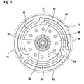
- eine Draufsicht einer Einzelheit der Vorrichtung in
Fig. 1 , - Fig. 4
- einen schematischen Schnitt entsprechend demjenigen in
Fig. 2 einer Einzelheit einer Vorrichtung gemäß einem zweiten Ausführungsbeispiel. - In den Zeichnungen ist eine Vorrichtung 10 zur Durchflussregelung eines flüssigen oder gasförmigen Mediums gezeigt, wobei diese Vorrichtung 10 insbesondere zur Dosierung eines zuzumischenden Fluids in ein Abgasreinigungssystem ausgebildet ist. Die Vorrichtung 10 weist einen Elektromagneten 11 auf, an den ein elektrischer Steckverbinder 12 angeschlossen ist. Der Elektromagnet 11 weist in einem Magnetgehäuse 13 eine Magnetspule 14 mit Magnetkern 15 und endseitiger Magnetplatte 16 auf. Der Elektromagnet 11 ist zur Betätigung eines gefriertauglichen Dosierventils 17 ausgebildet, das ein Ventilglied 18 in einem Ventilraum 19 eines Ventilkörpers 20 zur Steuerung eines dortigen Ventilsitzes 21 aufweist. Der Ventilkörper 20 ist in eine Aufnahme 22 eines Gehäuses 23 eingesteckt, das einen Fluideinlaß 24 und einen Fluidauslaß 25 enthält. Eine nur schematisch angedeutete Feder 26 erzeugt eine Federkraft, mit der das Dosierventil 17 über den Elektromagneten 11 in der Aufnahme 22 des Gehäuses 23 mit vorgegebener Kraft eingedrückt gehalten wird.
- Insbesondere dann, wenn derartige Vorrichtungen 10 zur Dosierung von Reduktionsmitteln, insbesondere Harnstoff-Wasser-Lösungen, eingesetzt werden, z. B. für SCR-Abgasnachbehandlungseinrichtungen, ist das Dosierventil 17 insbesondere auf Gefriertauglichkeit auszurichten; denn aufgrund des hohen Wasseranteils in einer Harnstoff-Wasser-Lösung gefriert die in Betrieb unter Druck stehende Lösung schon bei geringen negativen °Celsius, z. B. bei minus 11° Celsius, wobei diese Lösung z. B. um etwa 10 % expandiert. Aufgrund dieses Verhaltens ist das Dosierventil 17 so auszulegen, dass dieses einerseits nicht beschädigt wird und anderseits ein gutes Einspritz-/Sprühverhalten hat sowie eine zuverlässige Abdichtung nach außen gewährleistet ist. Bei üblichen Ventilen kann das mittels des Ventilgliedes 18 gesteuerte Fluid auch in den Bereich der Magnetspule 14 gelangen. Bei der Steuerung eines zuvor beschriebenen Fluids würde die Magnetspule 14 als relativ weiches Bauteil beim Einfrieren und bei der Volumenzunahme um ca. 10 % deformiert und dadurch beschädigt. Um dem entgegenzuwirken, ist die Magnetspule 14 gegenüber dem Ventilraum 19 deformationsgeschützt. Die Magnetspule 14 ist gegenüber dem Ventilraum 19 mittels einer Dichtungseinrichtung 30 abgedichtet, wodurch verhindert ist, dass das Fluid überhaupt in den Bereich der Magnetspule 14 gelangt. Die Dichtungseinrichtung 30 weist eine zwischen der Magnetspule 14 und dem Magnetkern 15 und/oder der Magnetplatte 16 angeordnete Dichtung 31 auf, die als Umfangsdichtung um den Magnetkern 15 ausgebildet ist. Beim ersten Ausführungsbeispiel gemäß
Fig. 1 bis 3 stellt die Dichtung 31 eine erste Dichtung dar, die zwischen der Magnetspule 14 und dem Magnetkern 15 vorgesehen und als radiale Dichtung ausgebildet ist, die in einer Ringnut 32 des Magnetkerns 15 liegt. Die Dichtungseinrichtung 30 weist beim ersten Ausführungsbeispiel gemäßFig. 1 bis 3 ferner mindestens eine zweite Dichtung 33 auf, die zwischen der Magnetspule 14 und der Magnetplatte 16 angeordnet und als axiale Dichtung ausgebildet ist. Der zwischen der Magnetplatte 16 und Ventilkörper 20 ausgebildete Ventilraum 19 ist mittels einer Dichtung 34 nach außen abgedichtet, die zwischen der Magnetplatte 16 und dem Ventilkörper 20 angeordnet ist. Die Dichtungen 31, 33 und 34 bestehen jeweils aus O-Ringen. - Die Dichtungseinrichtung 30 weist einen metallischen Dichtungshalter 35 auf, der zwischen der Magnetspule 14 und dem Magnetkern 15 und der Magnetplatte 16 angeordnet ist, wobei der Dichtungshalter 35 mindestens eine der Dichtungen 31, 33, beim ersten Ausführungsbeispiel beide Dichtungen 31, 33, aufnimmt. Der Dichtungshalter 35 weist einen Ringteil 36 auf, der den Magnetkern 15 umfasst und sich an die Magnetspule 14 anschließt und die eine radiale Dichtung 31 enthält, die am Magnetkern 15 anliegt. Dieser Ringteil 36 ist als Zylinderhülse ausgebildet. Der Dichtungshalter 35 weist ferner einen axialen Ringteil 37 auf, der sich axial zwischen der Magnetspule 14 und der Magnetplatte 16 erstreckt und die axiale Dichtung 33 enthält, die an der Magnetplatte 16 anliegt. Dieser axiale Ringteil 37 schließt sich an den Ringteil 36 in Form der Zylinderhülse an und ist mit diesem einstückig. Der Dichtungshalter 35 ist als im Querschnitt U-förmiger Ring ausgebildet, wobei die U-Basis an der Magnetspule 14 anliegt, der innere U-Schenkel die den Magnetanker 15 umgebende Zylinderhülse bildet und der äußere U-Schenkel 38 sich axial zwischen der Magnetspule 14 und der Magnetplatte 16 erstreckt. Auf diese Weise ist die relativ weiche Magnetspule 14 mittels des metallischen Dichtungshalters 35 abgedeckt und geschützt und mittels der Dichtungen 31 und 33 zuverlässig in Bezug auf den das Fluid führenden Ventilraum 19 abgedichtet, so dass bei etwaigem Einfrieren bei tiefen Außentemperaturen und Volumenexpansion des Fluids diese vom Dichtungshalter 35 abgefangen wird und durch die Dichtungen 31, 33 das Fluid von der Magnetspule 14 ferngehalten wird und eine Beaufschlagung und etwaige Deformation der Magnetspule 14 verhindert ist.
- In den Ventilraum 19 münden die Einlaßöffnungen 39 von z. B. drei Einlaßkanälen 40, die mit mindestens einem Zufuhrkanal 41 im Ventilkörper 20 verbunden sind, z. B. über einen Ringkanal 42. Der Zufuhrkanal 41 steht mit dem Fluideinlaß 24 in Verbindung. In den Ventilraum 19 mündet ferner mindestens eine Auslaßöffnung 43 mindestens eines vorzugsweise zentralen Auslaßkanals 44, der mit dem Fluidauslaß 25 in Verbindung steht.
- Der Ventilsitz 21 ist als überstehender, etwa schneidenartiger Ringsitz 27 ausgebildet, wobei die Auslaßöffnung 43 in die Öffnung dieses Ringsitzes 27 ausmündet. Der Auslaßkanal 44 ist am unteren Ende des Ventilkörpers 20 in Bezug auf das Gehäuse 23 mittels einer axialen Dichtung 45 abgedichtet. Der Ventilkörper 20 ist stufenförmig. Er weist auf dem Axialbereich, der sich oberhalb des Zufuhrkanals 41 erstreckt, einen größeren Durchmesser auf als auf dem Axialbereich, der sich unterhalb des Zufuhrkanals 41 erstreckt. Auf beiden Axialseiten des Zufuhrkanals 41 enthält der Ventilkörper 20 in einer jeweiligen Ringnut 46, 47 eine Umfangsdichtung 48, 49, z. B. einen Dichtungsring, zur Abdichtung des Ventilkörpers 20 gegenüber der Aufnahme 22 im Gehäuse 23.
- Das Ventilglied 18 weist einen Flachanker 51 geringer Masse im Ventilraum 19 zwischen der Magnetplatte und dem Ventilkörper 20 auf. Der Flachanker 51 ist Teil des Magnetkreises des Elektromagneten 11 und wird bei Erregung der Magnetspule 14 in
Fig. 1 und2 angezogen und nach oben bewegt, wodurch das Ventilglied 18 vom Ventilsitz 21 abhebt und den Durchlass des Fluids von den Einlaßkanälen 40 über die jeweilige Einlaßöffnung 39 und den Ventilraum 19 in die Auslaßöffnung 43 und zum Auslaßkanal 44 freigibt. Der Flachanker 51 weist einen äußeren Ring 52 auf, der zwischen der Magnetplatte 16 und dem Ventilkörper 20 gehalten ist, wobei eine radial vorspringende Nase 53 eine Verdrehsicherung bewirkt. Ferner weist der Flachanker 51 eine mittlere Ankerscheibe 54 auf, die über gebogene federnde Schenkel 55 mit dem Ring 52 verbunden und diesem gegenüber beweglich ist. Diese Ankerscheibe 54 stellt das bewegliche, den Ventildurchgang steuernde Element des Ventilgliedes 18 dar. Die Ankerscheibe 54 ist mittels Löchern 56 zum Fluidausgleich durchbrochen. Die federnden Schenkel 55 erzeugen eine federnde Rückstellkraft in Schließrichtung und Schließstellung gemäßFig. 2 . Sie wirken bei der Ventilbetätigung als Rückstellfedern. Am unteren Ende des Magnetkerns 15 ist in diesem mindestens eine Feder 57 enthalten, die z. B. als zylindrische Schraubenfeder ausgebildet ist. Die Feder 57 ist in einer Bohrung 58 des Magnetkerns 15 gehalten und darin zentriert. Mit dem anderen Ende ist die Feder 57 am Ventilglied 18 abgestützt und dort in einer Vertiefung 59 aufgenommen und zentriert. Die Feder 57 ist als Schließfeder und zur Sicherung eines vorgegebenen Gegendruckes ausgebildet. Sie trägt zusätzlich zu den federnden Schenkeln 55 der Ankerscheibe 54 zur Steigerung der RückschaltGeschwindigkeit des Dosierventil 17 bei. - Die Ankerscheibe 54 weist auf der dem Ventilsitz 21 zugewandten Seite eine Dichtungsplatte 60 auf, die in der Schließstellung auf dem Ringsitz 27 unter Abdichtung aufsitzt. Die Dichtungsplatte 60 liegt an der Unterseite der Ankerscheibe 54 auf. Über z. B. drei mit der Dichtungsplatte 60 einstückige Pfosten 61, die die Ankerscheibe 64 durchsetzen, ist die Dichtungsplatte 60 mit der Ankerscheibe 54 verbunden, wobei die Pfosten 61 über die Oberseite der Ankerscheibe 54 mit bogenförmigen Abschnitten 62 überstehen und jeweilige Dämpfungsglieder 63 bilden. Die Dichtungsplatte 60 ist mit den Pfosten 61 einstückig und besteht aus elastischem Material, z. B. einem Elastomer.
- Das Dosierventil 17 befindet sich in
Fig. 1 und2 in der geschlossenen Stellung. Wird die Magnetspule 14 erregt und ein Magnetkreis erzeugt, wird durch diesen die Ankerscheibe 54 gegen die Wirkung der Feder 57 und der federnden Schenkel 55 inFig. 1 und2 nach oben bewegt. Dabei wirken die Pfosten 61 und Abschnitte 62 als Dämpfungsglieder 63, die bei dieser Bewegung ein etwaiges Anschlagen am Magnetkern 15 dämpfen. Die Feder 57 wird dabei zusammengedrückt. Bei Entregung der Magnetspule 14 erfolgt schlagartig und vorzugsweise innerhalb weniger als 5 msec ein Schließen des Ventilgliedes 18 aufgrund der Rückstellkraft der Feder 57 und der federnden Schenkel 55 der Ankerscheibe 54. Die Vorrichtung 10 hat den Vorteil, dass das Dosierventil 17 in kurzer Zeit von z. B. weniger als 5 msec öffnen und schließen kann und dabei ein sauberes, reproduzierbares Einspritzen des unter Druck, z. B. von 8 bar, zugeführten Fluids ohne Vor- und Nachtropfen bewirkt. Dabei ist sichergestellt, dass am Ventilausgang beim Auslaßkanal 44 keine Lufteinschlüsse im Fluid, insbesondere Reduktionsmittel, vorkommen, die sonst zum Nachtropfen führen würden. Die Magnetspule 14 ist mittels des metallischen Dichtungshalters 35 und im übrigen der Magnetplatte 16 abgedeckt und deformationsgeschützt. Ferner ist die Magnetspule 14 über die Dichtungseinrichtung 30, bestehend aus dem Dichtungshalter 35 mit der ersten radialen Dichtung 31 und der zweiten axialen Dichtung 33, in Bezug auf den Ventilraum 19 einfriersicher abgedichtet, so dass kein Fluid vom Ventilraum 19 ausgehend zur Magnetspule 14 gelangen kann und beim Gefrieren und bei der Volumenexpansion sonst die Magnetspule 14 deformieren könnte. Die Magnetspule 14 ist also einfriersicher geschützt. Die Umfangsdichtung 48 bewirkt eine einfriersichere Abdichtung nach außen. Die Umfangsdichtung 49 bewirkt eine einfriersichere Abdichtung zwischen dem Fluideinlaß 24 mit Zufuhrkanal 41 und dem Fluidauslaß 25 mit Auslaßkanal 44, wobei die axiale Dichtung 45 am unteren Ende des Ventilkörpers 20 als axiale Abdichtung zur Vermeidung von Lufteinschlüssen dient. Die axiale Dichtung 45 sorgt für eine von Lufteinschlüssen freie Verbindung zwischen dem Auslaßkanal 44 und dem Fluidauslaß 25. Eine solche ist nur im nicht gefrorenen Zustand erforderlich, da nur in diesem Zustand eine Dosierung mittels des Dosierventiles 17 geschieht. Sollte sich ein als Reduktionsmittel gesteuertes Fluid im Bereich zwischen der Aufnahme 22 und dem Ventilkörper 20 ansammeln und aufgrund dessen bei Minustemperaturen gefrieren und sich eine Volumenzunahme ergeben, kann die Einheit aus Elektromagnet 11 und Dosierventil 17 axial gegen die Wirkung der Feder 26 aus dem Gehäuse 23 herausgeschoben werden und auf diese Weise ausweichen, ohne dass eine Beschädigung oder gar Zerstörung des Dosierventils 17 geschieht. Die Vorrichtung 10 ist daher mit besonderem Vorteil für die Steuerung eines Mediums in Form eines Reduktionsmittels, insbesondere einer Harnstoff-Wasser-Lösung, für eine SCR-Abgasnachbehandlungseinrichtung geeignet. Dabei ist gewährleistet, dass selbst beim Gefrieren keine Beschädigung erfolgt und andererseits ein gutes Einspritzen/Sprühen erfolgen kann sowie ein zuverlässiges Abdichten nach außen gegeben ist. Da das Ventilglied 18 in Gestalt des Flachankers 51 eine sehr kleine Masse hat, ermöglicht das Dosierventil 17 ein schnelles Schalten, das heißt einen schnellen Wechsel zwischen Öffnen und Schließen, wobei das Öffnen und Schließen z.B. in weniger als 5 sec erfolgen kann und dadurch über eine Einspritzdüse ein sauberes Einspritzen des Fluids ermöglicht ist. - Bei dem in
Fig. 4 gezeigten zweiten Ausführungsbeispiel sind für die Teile, die dem ersten Ausführungsbeispiel entsprechen, gleiche Bezugszeichen verwendet, so dass dadurch zur Vermeidung von Wiederholungen auf die Beschreibung des ersten Ausführungsbeispieles Bezug genommen ist. - Das zweite Ausführungsbeispiel gemäß
Fig. 4 unterscheidet sich vom ersten Ausführungsbeispiel dadurch, dass nur eine Dichtung 31 zwischen der Magnetspule 14 und dem Magnetkern 15 und der Magnetplatte 16 vorgesehen ist, die als radiale Dichtung ausgebildet ist. Der Dichtungshalter 35 weist nur den axialen Ringteil 37 auf, der als Ringscheibe 70 mit daran anschließendem äußeren Schenkel 38 ausgebildet ist, der sich etwa achsparallel zwischen der Magnetspule 14 und der Magnetplatte 16 erstreckt. Die Magnetplatte 16 weist eine zentrale Öffnung 71 auf und enthält im Bereich dieser eine etwa kegelstumpfförmige Einsenkung 72 als Anlagefläche für die radiale Dichtung 31. Auch bei dieser vereinfachten Gestaltung der Dichtungseinrichtung 30 ist eine zuverlässige Abdichtung der Magnetspule 14 gegenüber dem Ventilraum 19 gewährleistet.
Claims (15)
- Vorrichtung zur. Durchflussregelung eines flüssigen oder gasförmigen Mediums, insbesondere zur Dosierung eines zuzumischenden Fluids in ein Abgasreinigungssystem, mit einem Elektromagneten (11), der in einem Magnetgehäuse (13) eine Magnetspule (14) mit Magnetkern (15) und endseitiger Magnetplatte (16) aufweist und ein Ventilglied (18) in einem Ventilraum (19) eines Ventilkörpers (20) zur Steuerung eines dortigen Ventilsitzes (21) betätigt,
dadurch gekennzeichnet,
dass die Magnetspule (14) gegenüber dem Ventilraum (19) deformationsgeschützt ist. - Vorrichtung nach Anspruch 1,
dadurch gekennzeichnet,
dass die Magnetspule (14) gegenüber dem Ventilraum (19) mittels einer Dichtungseinrichtung (30) abgedichtet ist. - Vorrichtung nach Anspruch 2,
dadurch gekennzeichnet,
dass die Dichtungseinrichtung (30) eine zwischen der Magnetspule (14) und dem Magnetkern (15) und /oder der Magnetplatte (16) angeordnete Dichtung (31) aufweist, die als Umfangsdichtung um den Magnetkern (15) ausgebildet ist. - Vorrichtung nach Anspruch 2,
dadurch gekennzeichnet,
dass die Dichtungseinrichtung mindestens eine zwischen der Magnetspule (14) und dem Magnetkern (15) angeordnete erste Dichtung (31), die als radiale Dichtung ausgebildet ist, und mindestens eine zwischen der Magnetspule (14) und der Magnetplatte (16) angeordnete zweite Dichtung (33) aufweist, die als axiale Dichtung ausgebildet ist. - Vorrichtung nach einem der Ansprüche 1 bis 4,
dadurch gekennzeichnet,
dass die Dichtungseinrichtung (30) einen metallischen Dichtungshalter (35) aufweist, der zwischen der Magnetspule (14) und dem Magnetkern (15) und der Magnetplatte (16) angeordnet ist und die mindestens eine zwischen der Magnetspule (14) und der Magnetplatte (16) und/oder dem Magnetkern (15) befindliche Dichtung (31) aufnimmt und der vorzugsweise einen Ringteil (36) aufweist, der den Magnetkern (15) umfasst und sich an die Magnetspule (14) anschließt und die eine radiale Dichtung (31) enthält, die am Magnetkern (15) anliegt, wobei der Ringteil (36) z. B. als Zylinderhülse ausgebildet ist. - Vorrichtung nach Anspruch 5,
dadurch gekennzeichnet,
dass der Dichtungshalter (35) einen sich axial zwischen der Magnetspule (14) und der Magnetplatte (16) erstreckenden axialen Ringteil (37) aufweist, der die axiale Dichtung (33) enthält, die an der Magnetplatte (16) anliegt, und vorzugsweise, dass der axiale Ringteil (37) an den Ringteil (36), z. B. die Zylinderhülse, anschließt und mit diesem einstückig ist, wobei der Ringteil (36), z. B. die Zylinderhülse, die radiale Dichtung (31), die am Magnetanker (15) anliegt, und der axiale Ringteil (37) die axiale Dichtung (33) aufnimmt, die an der Magnetplatte (16) anliegt. - Vorrichtung nach einem der Ansprüche 5 oder 6,
dadurch gekennzeichnet,
dass der Dichtungshalter (35) als im Querschnitt etwa U-förmiger Ring ausgebildet ist, wobei die U-Basis an der Magnetspule (14) anliegt, der innere U-Schenkel die den Magnetanker (15) umgebende Zylinderhülse (36) bildet und der äußere U-Schenkel (38) sich axial zwischen der Magnetspule (14) und der Magnetplatte (16) erstreckt. - Vorrichtung nach einem der Ansprüche 1 bis 7,
dadurch gekennzeichnet,
dass der Ventilraum (19) zwischen der Magnetplatte (16) und einem den Ventilsitz (21) enthaltenden Ventilkörper (20) vorgesehen ist und mittels einer Dichtung (34) zwischen beiden nach außen abgedichtet ist, wobei in den Ventilraum (19) die Einlaßöffnung (39) mindestens eines Einlaßkanals (40) und die Auslaßöffnung (43) mindestens eines vorzugsweise zentralen Auslaßkanals (44) münden. - Vorrichtung nach einem der Ansprüche 1 bis 8,
dadurch gekennzeichnet,
dass das Ventilglied (18) einen Flachanker (51) geringer Masse im Ventilraum (19) zwischen der Magnetplatte (16) und dem Ventilkörper (20) aufweist. - Vorrichtung nach Anspruch 9,
dadurch gekennzeichnet,
dass der Flachanker (51) eine mittlere, über federnde Schenkel (55) beweglich verbundene Ankerscheibe (54) als betätigbares Ventilglied (18) aufweist und die federnden Schenkel (55) als Rückstellfedern ausgebildet sind. - Vorrichtung nach einem der Ansprüche 1 bis 10,
dadurch gekennzeichnet,
dass die Ankerscheibe (54) auf der Seite, die dem Ventilsitz (21) zugewandt ist, eine Dichtungsplatte (60) und auf der gegenüberliegenden Seite mindestens ein Dämpfungsglied (63) aufweist. - Vorrichtung nach Anspruch 11,
dadurch gekennzeichnet,
dass das mindestens eine Dämpfungsglied (63) Teil der Dichtungsplatte (60) ist und diese aus elastischem Material, z. B. einem Elastomer, gebildet ist. - Vorrichtung nach einem der Ansprüche 1 bis 12,
dadurch gekennzeichnet,
dass der Ventilsitz (21) als überstehender, etwa schneidenartiger Ringsitz (27) ausgebildet ist. - Vorrichtung nach einem der Ansprüche 1 bis 13,
dadurch gekennzeichnet,
dass im Magnetkern (15) mindestens eine Feder (57), z. B. zylindrische Schraubenfeder, enthalten ist, die einerseits am Magnetkern (15) und andererseits am Ventilglied (18) abgestützt und zentriert ist und als Schließfeder und zur Sicherung eines Gegendruckes ausgebildet ist. - Vorrichtung nach einem der Ansprüche 8 bis 14,
dadurch gekennzeichnet,
dass der in die Öffnung des Ventilsitzes (21) ausmündende Auslaßkanal (44) am Ende des Ventilkörpers (20) in Bezug auf eine Aufnahme (22) eines Gehäuses (23), das einen anschließenden Fluidauslaß (25) enthält, mittels einer axialen Dichtung (45) abgedichtet ist, und vorzugsweise, dass der mindestens eine Einlaßkanal (40) des Ventilkörpers (20) mit mindestens einem Zufuhrkanal (41) im Ventilkörper (20) verbunden ist, der mit einem Fluideinlaß (24) des Gehäuses (23) in Verbindung steht, und vorzugsweise, dass der Ventilkörper (20) axial beidseitig des Zufuhrkanals (41) in einer jeweiligen Ringnut (46, 47) eine Umfangsdichtung (48, 49), z. B. einen Dichtungsring, zur Abdichtung des Ventilkörpers (20) gegenüber der Aufnahme (22) des Gehäuses (23) enthält, in die der Ventilkörper (20) eingesteckt ist.
Priority Applications (2)
| Application Number | Priority Date | Filing Date | Title |
|---|---|---|---|
| EP11002067.4A EP2500610B1 (de) | 2011-03-12 | 2011-03-12 | Vorrichtung zur Durchflussregelung eines flüssigen oder gasförmigen Mediums |
| US13/108,581 US20120228533A1 (en) | 2011-03-12 | 2011-05-16 | Device for the flow control of a liquid or gaseous medium |
Applications Claiming Priority (1)
| Application Number | Priority Date | Filing Date | Title |
|---|---|---|---|
| EP11002067.4A EP2500610B1 (de) | 2011-03-12 | 2011-03-12 | Vorrichtung zur Durchflussregelung eines flüssigen oder gasförmigen Mediums |
Publications (2)
| Publication Number | Publication Date |
|---|---|
| EP2500610A1 true EP2500610A1 (de) | 2012-09-19 |
| EP2500610B1 EP2500610B1 (de) | 2016-11-30 |
Family
ID=44343066
Family Applications (1)
| Application Number | Title | Priority Date | Filing Date |
|---|---|---|---|
| EP11002067.4A Active EP2500610B1 (de) | 2011-03-12 | 2011-03-12 | Vorrichtung zur Durchflussregelung eines flüssigen oder gasförmigen Mediums |
Country Status (2)
| Country | Link |
|---|---|
| US (1) | US20120228533A1 (de) |
| EP (1) | EP2500610B1 (de) |
Cited By (4)
| Publication number | Priority date | Publication date | Assignee | Title |
|---|---|---|---|---|
| DE102012021664A1 (de) * | 2012-11-07 | 2014-05-08 | L'orange Gmbh | Injektor für Reduktionsmittel |
| DE102016014432A1 (de) * | 2016-12-05 | 2018-06-07 | Thomas Magnete Gmbh | Schaltend betätigtes Ventil |
| EP3339700A1 (de) * | 2016-12-23 | 2018-06-27 | Andreas Stihl AG & Co. KG | Elektromagnetisches ventil |
| WO2021148167A1 (de) * | 2020-01-22 | 2021-07-29 | Robert Bosch Gmbh | Ventileinrichtung, pumpenmodul, abgasnachbehandlungssystem |
Families Citing this family (5)
| Publication number | Priority date | Publication date | Assignee | Title |
|---|---|---|---|---|
| US10054243B1 (en) * | 2015-03-04 | 2018-08-21 | Edmund F. Kelly | Dual spring flow control valve |
| CN107532744B (zh) * | 2015-04-28 | 2019-11-05 | 派克汉尼芬公司 | 低剖面微型螺线管比例阀 |
| DE102018102758B4 (de) * | 2018-02-07 | 2020-01-16 | Kendrion (Villingen) Gmbh | Feder für ein Rückschlagventil, Rückschlagventil mit einer derartigen Feder, regelbarer Schwingungsdämpfer mit einem solchen Rückschlagventil sowie Kraftfahrzeug mit einem derartigen regelbaren Schwingungsdämpfer |
| US10704444B2 (en) | 2018-08-21 | 2020-07-07 | Tenneco Automotive Operating Company Inc. | Injector fluid filter with upper and lower lip seal |
| DE102020123249A1 (de) | 2020-09-07 | 2022-03-10 | Knorr-Bremse Systeme für Nutzfahrzeuge GmbH | Plattenanker-Dämpfungseinrichtung für ein Kippankerventil, Plattenanker sowie Kippankerventil mit einer Plattenanker-Dämpfungseinrichtung |
Citations (6)
| Publication number | Priority date | Publication date | Assignee | Title |
|---|---|---|---|---|
| GB2189010A (en) * | 1986-03-07 | 1987-10-14 | Alexander Controls Ltd | Apparatus for controlling the flow of gas |
| DE3801035A1 (de) * | 1987-03-30 | 1988-10-20 | Koganei Ltd | Solenoidventil |
| DE10112661A1 (de) * | 2001-03-16 | 2002-09-19 | Bosch Gmbh Robert | Magnetventil |
| US20060017034A1 (en) * | 2004-07-23 | 2006-01-26 | Smc Kabushiki Kaisha | Solenoid-operated valve |
| DE102004025062B4 (de) | 2004-05-18 | 2006-09-14 | Hydraulik-Ring Gmbh | Gefriertaugliches Dosierventil |
| DE102008023182A1 (de) * | 2008-05-10 | 2009-11-12 | Staiger Gmbh & Co. Kg | Ventil |
Family Cites Families (5)
| Publication number | Priority date | Publication date | Assignee | Title |
|---|---|---|---|---|
| DE4244113A1 (de) * | 1992-12-24 | 1994-06-30 | Bosch Gmbh Robert | Ventil zum dosierten Einleiten von verflüchtigtem Brennstoff in einen Ansaugkanal einer Brennkraftmaschine |
| DE4329760A1 (de) * | 1993-09-03 | 1995-03-09 | Bosch Gmbh Robert | Elektromagnetisch betätigbares Proportionalventil |
| US6220569B1 (en) * | 2000-01-07 | 2001-04-24 | Clippard Instrument Laboratory, Inc. | Electrically controlled proportional valve |
| JP2006153218A (ja) * | 2004-11-30 | 2006-06-15 | Keihin Corp | 燃料電池用電磁弁 |
| EP2400193B1 (de) * | 2010-06-23 | 2019-08-28 | Asco Numatics GmbH | Vorrichtung zur Durchflussregelung eines flüssigen oder gasförmigen Mediums |
-
2011
- 2011-03-12 EP EP11002067.4A patent/EP2500610B1/de active Active
- 2011-05-16 US US13/108,581 patent/US20120228533A1/en not_active Abandoned
Patent Citations (6)
| Publication number | Priority date | Publication date | Assignee | Title |
|---|---|---|---|---|
| GB2189010A (en) * | 1986-03-07 | 1987-10-14 | Alexander Controls Ltd | Apparatus for controlling the flow of gas |
| DE3801035A1 (de) * | 1987-03-30 | 1988-10-20 | Koganei Ltd | Solenoidventil |
| DE10112661A1 (de) * | 2001-03-16 | 2002-09-19 | Bosch Gmbh Robert | Magnetventil |
| DE102004025062B4 (de) | 2004-05-18 | 2006-09-14 | Hydraulik-Ring Gmbh | Gefriertaugliches Dosierventil |
| US20060017034A1 (en) * | 2004-07-23 | 2006-01-26 | Smc Kabushiki Kaisha | Solenoid-operated valve |
| DE102008023182A1 (de) * | 2008-05-10 | 2009-11-12 | Staiger Gmbh & Co. Kg | Ventil |
Cited By (7)
| Publication number | Priority date | Publication date | Assignee | Title |
|---|---|---|---|---|
| DE102012021664A1 (de) * | 2012-11-07 | 2014-05-08 | L'orange Gmbh | Injektor für Reduktionsmittel |
| DE102012021664B4 (de) * | 2012-11-07 | 2017-02-16 | L'orange Gmbh | Injektor für Reduktionsmittel |
| DE102016014432A1 (de) * | 2016-12-05 | 2018-06-07 | Thomas Magnete Gmbh | Schaltend betätigtes Ventil |
| EP3339700A1 (de) * | 2016-12-23 | 2018-06-27 | Andreas Stihl AG & Co. KG | Elektromagnetisches ventil |
| CN108240500A (zh) * | 2016-12-23 | 2018-07-03 | 安德烈·斯蒂尔股份两合公司 | 电磁阀 |
| CN108240500B (zh) * | 2016-12-23 | 2021-09-07 | 安德烈·斯蒂尔股份两合公司 | 电磁阀 |
| WO2021148167A1 (de) * | 2020-01-22 | 2021-07-29 | Robert Bosch Gmbh | Ventileinrichtung, pumpenmodul, abgasnachbehandlungssystem |
Also Published As
| Publication number | Publication date |
|---|---|
| EP2500610B1 (de) | 2016-11-30 |
| US20120228533A1 (en) | 2012-09-13 |
Similar Documents
| Publication | Publication Date | Title |
|---|---|---|
| EP2500610B1 (de) | Vorrichtung zur Durchflussregelung eines flüssigen oder gasförmigen Mediums | |
| DE4414242A1 (de) | Kraftstoffeinspritzeinrichtung für Brennkraftmaschinen | |
| EP3161299B1 (de) | Gasventil | |
| EP3478957B1 (de) | Ventil zum eindüsen von gasförmigem kraftstoff | |
| EP1315900A1 (de) | Brennstoffeinspritzventil | |
| EP1309789B1 (de) | Brennstoffeinspritzventil | |
| EP2021616B1 (de) | Magnetventil mit geflutetem ankerraum | |
| WO2018228740A1 (de) | Gas-druckbegrenzungsventil mit ringspaltsitz zum steuern und ablassen von einem gasförmigen medium | |
| DE102017209901A1 (de) | Gas-Druckbegrenzungsventil zum Steuern und Ablassen von einem gasförmigen Medium | |
| WO2004051072A1 (de) | Brennstoffeinspritzventil | |
| DE102009002484A1 (de) | Einspritzventil für eine Abgasnachbehandlungseinrichtung | |
| WO2012019879A1 (de) | Einspritzvorrichtung zum einbringen einer harnstofflösung in den abgasstrang einer brennkraftmaschine | |
| WO2015052005A1 (de) | Steuerventil | |
| EP2818689B1 (de) | Kraftstoffeinspritzventil | |
| DE60318526T2 (de) | Kraftstoffeinspritzvorrichtung für eine verbrennungskraftmaschine mit hydraulischer stiftbetätigung | |
| DE102008042531A1 (de) | Ventilanordnung zur Kraftstoffhochdruckeinspritzung | |
| DE102013220775B4 (de) | Ventileinrichtung für ein Fluidsystem | |
| DE10308914A1 (de) | Brennstoffeinspritzventil | |
| DE102014101664A1 (de) | Druckregelventil | |
| EP2469140A1 (de) | Ventil | |
| DE102016209022A1 (de) | Steuerventil für ein Kraftstoffeinspritzventil | |
| WO2014202473A1 (de) | Druckregelventil | |
| DE102013224960A1 (de) | Kraftstoffinjektor | |
| WO2019170301A1 (de) | Ventil für das einspritzen von wasser in ein kraftstofffördermodul eines verbrennungsmotors, ventilmodul, dosiermodul und verbrennungsmotor | |
| WO2013050078A1 (de) | Einspritzventil |
Legal Events
| Date | Code | Title | Description |
|---|---|---|---|
| PUAI | Public reference made under article 153(3) epc to a published international application that has entered the european phase |
Free format text: ORIGINAL CODE: 0009012 |
|
| AK | Designated contracting states |
Kind code of ref document: A1 Designated state(s): AL AT BE BG CH CY CZ DE DK EE ES FI FR GB GR HR HU IE IS IT LI LT LU LV MC MK MT NL NO PL PT RO RS SE SI SK SM TR |
|
| AX | Request for extension of the european patent |
Extension state: BA ME |
|
| 17P | Request for examination filed |
Effective date: 20130225 |
|
| 17Q | First examination report despatched |
Effective date: 20151022 |
|
| REG | Reference to a national code |
Ref country code: DE Ref legal event code: R079 Ref document number: 502011011215 Country of ref document: DE Free format text: PREVIOUS MAIN CLASS: F16K0031060000 Ipc: F01N0003200000 |
|
| RIC1 | Information provided on ipc code assigned before grant |
Ipc: F01N 3/20 20060101AFI20160503BHEP Ipc: F16K 31/06 20060101ALI20160503BHEP |
|
| GRAP | Despatch of communication of intention to grant a patent |
Free format text: ORIGINAL CODE: EPIDOSNIGR1 |
|
| INTG | Intention to grant announced |
Effective date: 20160613 |
|
| GRAS | Grant fee paid |
Free format text: ORIGINAL CODE: EPIDOSNIGR3 |
|
| GRAJ | Information related to disapproval of communication of intention to grant by the applicant or resumption of examination proceedings by the epo deleted |
Free format text: ORIGINAL CODE: EPIDOSDIGR1 |
|
| GRAL | Information related to payment of fee for publishing/printing deleted |
Free format text: ORIGINAL CODE: EPIDOSDIGR3 |
|
| GRAP | Despatch of communication of intention to grant a patent |
Free format text: ORIGINAL CODE: EPIDOSNIGR1 |
|
| INTC | Intention to grant announced (deleted) | ||
| GRAA | (expected) grant |
Free format text: ORIGINAL CODE: 0009210 |
|
| INTG | Intention to grant announced |
Effective date: 20161004 |
|
| AK | Designated contracting states |
Kind code of ref document: B1 Designated state(s): AL AT BE BG CH CY CZ DE DK EE ES FI FR GB GR HR HU IE IS IT LI LT LU LV MC MK MT NL NO PL PT RO RS SE SI SK SM TR |
|
| REG | Reference to a national code |
Ref country code: CH Ref legal event code: EP Ref country code: GB Ref legal event code: FG4D Free format text: NOT ENGLISH |
|
| REG | Reference to a national code |
Ref country code: AT Ref legal event code: REF Ref document number: 850013 Country of ref document: AT Kind code of ref document: T Effective date: 20161215 |
|
| REG | Reference to a national code |
Ref country code: IE Ref legal event code: FG4D Free format text: LANGUAGE OF EP DOCUMENT: GERMAN |
|
| REG | Reference to a national code |
Ref country code: DE Ref legal event code: R096 Ref document number: 502011011215 Country of ref document: DE |
|
| PG25 | Lapsed in a contracting state [announced via postgrant information from national office to epo] |
Ref country code: LV Free format text: LAPSE BECAUSE OF FAILURE TO SUBMIT A TRANSLATION OF THE DESCRIPTION OR TO PAY THE FEE WITHIN THE PRESCRIBED TIME-LIMIT Effective date: 20161130 |
|
| REG | Reference to a national code |
Ref country code: FR Ref legal event code: PLFP Year of fee payment: 7 |
|
| REG | Reference to a national code |
Ref country code: LT Ref legal event code: MG4D |
|
| REG | Reference to a national code |
Ref country code: NL Ref legal event code: MP Effective date: 20161130 |
|
| PG25 | Lapsed in a contracting state [announced via postgrant information from national office to epo] |
Ref country code: SE Free format text: LAPSE BECAUSE OF FAILURE TO SUBMIT A TRANSLATION OF THE DESCRIPTION OR TO PAY THE FEE WITHIN THE PRESCRIBED TIME-LIMIT Effective date: 20161130 Ref country code: GR Free format text: LAPSE BECAUSE OF FAILURE TO SUBMIT A TRANSLATION OF THE DESCRIPTION OR TO PAY THE FEE WITHIN THE PRESCRIBED TIME-LIMIT Effective date: 20170301 Ref country code: LT Free format text: LAPSE BECAUSE OF FAILURE TO SUBMIT A TRANSLATION OF THE DESCRIPTION OR TO PAY THE FEE WITHIN THE PRESCRIBED TIME-LIMIT Effective date: 20161130 Ref country code: NO Free format text: LAPSE BECAUSE OF FAILURE TO SUBMIT A TRANSLATION OF THE DESCRIPTION OR TO PAY THE FEE WITHIN THE PRESCRIBED TIME-LIMIT Effective date: 20170228 |
|
| PG25 | Lapsed in a contracting state [announced via postgrant information from national office to epo] |
Ref country code: HR Free format text: LAPSE BECAUSE OF FAILURE TO SUBMIT A TRANSLATION OF THE DESCRIPTION OR TO PAY THE FEE WITHIN THE PRESCRIBED TIME-LIMIT Effective date: 20161130 Ref country code: ES Free format text: LAPSE BECAUSE OF FAILURE TO SUBMIT A TRANSLATION OF THE DESCRIPTION OR TO PAY THE FEE WITHIN THE PRESCRIBED TIME-LIMIT Effective date: 20161130 Ref country code: RS Free format text: LAPSE BECAUSE OF FAILURE TO SUBMIT A TRANSLATION OF THE DESCRIPTION OR TO PAY THE FEE WITHIN THE PRESCRIBED TIME-LIMIT Effective date: 20161130 Ref country code: PT Free format text: LAPSE BECAUSE OF FAILURE TO SUBMIT A TRANSLATION OF THE DESCRIPTION OR TO PAY THE FEE WITHIN THE PRESCRIBED TIME-LIMIT Effective date: 20170330 Ref country code: FI Free format text: LAPSE BECAUSE OF FAILURE TO SUBMIT A TRANSLATION OF THE DESCRIPTION OR TO PAY THE FEE WITHIN THE PRESCRIBED TIME-LIMIT Effective date: 20161130 Ref country code: PL Free format text: LAPSE BECAUSE OF FAILURE TO SUBMIT A TRANSLATION OF THE DESCRIPTION OR TO PAY THE FEE WITHIN THE PRESCRIBED TIME-LIMIT Effective date: 20161130 |
|
| PG25 | Lapsed in a contracting state [announced via postgrant information from national office to epo] |
Ref country code: NL Free format text: LAPSE BECAUSE OF FAILURE TO SUBMIT A TRANSLATION OF THE DESCRIPTION OR TO PAY THE FEE WITHIN THE PRESCRIBED TIME-LIMIT Effective date: 20161130 |
|
| PG25 | Lapsed in a contracting state [announced via postgrant information from national office to epo] |
Ref country code: RO Free format text: LAPSE BECAUSE OF FAILURE TO SUBMIT A TRANSLATION OF THE DESCRIPTION OR TO PAY THE FEE WITHIN THE PRESCRIBED TIME-LIMIT Effective date: 20161130 Ref country code: SK Free format text: LAPSE BECAUSE OF FAILURE TO SUBMIT A TRANSLATION OF THE DESCRIPTION OR TO PAY THE FEE WITHIN THE PRESCRIBED TIME-LIMIT Effective date: 20161130 Ref country code: EE Free format text: LAPSE BECAUSE OF FAILURE TO SUBMIT A TRANSLATION OF THE DESCRIPTION OR TO PAY THE FEE WITHIN THE PRESCRIBED TIME-LIMIT Effective date: 20161130 Ref country code: DK Free format text: LAPSE BECAUSE OF FAILURE TO SUBMIT A TRANSLATION OF THE DESCRIPTION OR TO PAY THE FEE WITHIN THE PRESCRIBED TIME-LIMIT Effective date: 20161130 Ref country code: CZ Free format text: LAPSE BECAUSE OF FAILURE TO SUBMIT A TRANSLATION OF THE DESCRIPTION OR TO PAY THE FEE WITHIN THE PRESCRIBED TIME-LIMIT Effective date: 20161130 |
|
| PG25 | Lapsed in a contracting state [announced via postgrant information from national office to epo] |
Ref country code: IT Free format text: LAPSE BECAUSE OF FAILURE TO SUBMIT A TRANSLATION OF THE DESCRIPTION OR TO PAY THE FEE WITHIN THE PRESCRIBED TIME-LIMIT Effective date: 20161130 Ref country code: BG Free format text: LAPSE BECAUSE OF FAILURE TO SUBMIT A TRANSLATION OF THE DESCRIPTION OR TO PAY THE FEE WITHIN THE PRESCRIBED TIME-LIMIT Effective date: 20170228 Ref country code: SM Free format text: LAPSE BECAUSE OF FAILURE TO SUBMIT A TRANSLATION OF THE DESCRIPTION OR TO PAY THE FEE WITHIN THE PRESCRIBED TIME-LIMIT Effective date: 20161130 |
|
| REG | Reference to a national code |
Ref country code: DE Ref legal event code: R097 Ref document number: 502011011215 Country of ref document: DE |
|
| PLBE | No opposition filed within time limit |
Free format text: ORIGINAL CODE: 0009261 |
|
| STAA | Information on the status of an ep patent application or granted ep patent |
Free format text: STATUS: NO OPPOSITION FILED WITHIN TIME LIMIT |
|
| REG | Reference to a national code |
Ref country code: CH Ref legal event code: PL |
|
| 26N | No opposition filed |
Effective date: 20170831 |
|
| PG25 | Lapsed in a contracting state [announced via postgrant information from national office to epo] |
Ref country code: MC Free format text: LAPSE BECAUSE OF FAILURE TO SUBMIT A TRANSLATION OF THE DESCRIPTION OR TO PAY THE FEE WITHIN THE PRESCRIBED TIME-LIMIT Effective date: 20161130 Ref country code: SI Free format text: LAPSE BECAUSE OF FAILURE TO SUBMIT A TRANSLATION OF THE DESCRIPTION OR TO PAY THE FEE WITHIN THE PRESCRIBED TIME-LIMIT Effective date: 20161130 |
|
| REG | Reference to a national code |
Ref country code: IE Ref legal event code: MM4A |
|
| PG25 | Lapsed in a contracting state [announced via postgrant information from national office to epo] |
Ref country code: LU Free format text: LAPSE BECAUSE OF NON-PAYMENT OF DUE FEES Effective date: 20170312 |
|
| PG25 | Lapsed in a contracting state [announced via postgrant information from national office to epo] |
Ref country code: IE Free format text: LAPSE BECAUSE OF NON-PAYMENT OF DUE FEES Effective date: 20170312 Ref country code: LI Free format text: LAPSE BECAUSE OF NON-PAYMENT OF DUE FEES Effective date: 20170331 Ref country code: CH Free format text: LAPSE BECAUSE OF NON-PAYMENT OF DUE FEES Effective date: 20170331 |
|
| REG | Reference to a national code |
Ref country code: BE Ref legal event code: MM Effective date: 20170331 |
|
| REG | Reference to a national code |
Ref country code: FR Ref legal event code: PLFP Year of fee payment: 8 |
|
| REG | Reference to a national code |
Ref country code: AT Ref legal event code: MM01 Ref document number: 850013 Country of ref document: AT Kind code of ref document: T Effective date: 20170312 |
|
| PG25 | Lapsed in a contracting state [announced via postgrant information from national office to epo] |
Ref country code: BE Free format text: LAPSE BECAUSE OF NON-PAYMENT OF DUE FEES Effective date: 20170331 |
|
| PG25 | Lapsed in a contracting state [announced via postgrant information from national office to epo] |
Ref country code: AT Free format text: LAPSE BECAUSE OF NON-PAYMENT OF DUE FEES Effective date: 20170312 |
|
| PG25 | Lapsed in a contracting state [announced via postgrant information from national office to epo] |
Ref country code: MT Free format text: LAPSE BECAUSE OF FAILURE TO SUBMIT A TRANSLATION OF THE DESCRIPTION OR TO PAY THE FEE WITHIN THE PRESCRIBED TIME-LIMIT Effective date: 20161130 |
|
| PG25 | Lapsed in a contracting state [announced via postgrant information from national office to epo] |
Ref country code: HU Free format text: LAPSE BECAUSE OF FAILURE TO SUBMIT A TRANSLATION OF THE DESCRIPTION OR TO PAY THE FEE WITHIN THE PRESCRIBED TIME-LIMIT; INVALID AB INITIO Effective date: 20110312 |
|
| PG25 | Lapsed in a contracting state [announced via postgrant information from national office to epo] |
Ref country code: CY Free format text: LAPSE BECAUSE OF NON-PAYMENT OF DUE FEES Effective date: 20161130 |
|
| PG25 | Lapsed in a contracting state [announced via postgrant information from national office to epo] |
Ref country code: MK Free format text: LAPSE BECAUSE OF FAILURE TO SUBMIT A TRANSLATION OF THE DESCRIPTION OR TO PAY THE FEE WITHIN THE PRESCRIBED TIME-LIMIT Effective date: 20161130 |
|
| PG25 | Lapsed in a contracting state [announced via postgrant information from national office to epo] |
Ref country code: TR Free format text: LAPSE BECAUSE OF FAILURE TO SUBMIT A TRANSLATION OF THE DESCRIPTION OR TO PAY THE FEE WITHIN THE PRESCRIBED TIME-LIMIT Effective date: 20161130 |
|
| PG25 | Lapsed in a contracting state [announced via postgrant information from national office to epo] |
Ref country code: AL Free format text: LAPSE BECAUSE OF FAILURE TO SUBMIT A TRANSLATION OF THE DESCRIPTION OR TO PAY THE FEE WITHIN THE PRESCRIBED TIME-LIMIT Effective date: 20161130 Ref country code: IS Free format text: LAPSE BECAUSE OF FAILURE TO SUBMIT A TRANSLATION OF THE DESCRIPTION OR TO PAY THE FEE WITHIN THE PRESCRIBED TIME-LIMIT Effective date: 20170330 |
|
| PGFP | Annual fee paid to national office [announced via postgrant information from national office to epo] |
Ref country code: FR Payment date: 20230222 Year of fee payment: 13 |
|
| PGFP | Annual fee paid to national office [announced via postgrant information from national office to epo] |
Ref country code: GB Payment date: 20230222 Year of fee payment: 13 Ref country code: DE Payment date: 20230221 Year of fee payment: 13 |