EP2500575B2 - Heizungsumwälzpumpe - Google Patents
Heizungsumwälzpumpe Download PDFInfo
- Publication number
- EP2500575B2 EP2500575B2 EP11002071.6A EP11002071A EP2500575B2 EP 2500575 B2 EP2500575 B2 EP 2500575B2 EP 11002071 A EP11002071 A EP 11002071A EP 2500575 B2 EP2500575 B2 EP 2500575B2
- Authority
- EP
- European Patent Office
- Prior art keywords
- plug
- terminal box
- socket
- housing
- motor housing
- Prior art date
- Legal status (The legal status is an assumption and is not a legal conclusion. Google has not performed a legal analysis and makes no representation as to the accuracy of the status listed.)
- Active
Links
Images


Classifications
-
- F—MECHANICAL ENGINEERING; LIGHTING; HEATING; WEAPONS; BLASTING
- F04—POSITIVE - DISPLACEMENT MACHINES FOR LIQUIDS; PUMPS FOR LIQUIDS OR ELASTIC FLUIDS
- F04D—NON-POSITIVE-DISPLACEMENT PUMPS
- F04D13/00—Pumping installations or systems
- F04D13/02—Units comprising pumps and their driving means
- F04D13/06—Units comprising pumps and their driving means the pump being electrically driven
- F04D13/0693—Details or arrangements of the wiring
-
- F—MECHANICAL ENGINEERING; LIGHTING; HEATING; WEAPONS; BLASTING
- F04—POSITIVE - DISPLACEMENT MACHINES FOR LIQUIDS; PUMPS FOR LIQUIDS OR ELASTIC FLUIDS
- F04D—NON-POSITIVE-DISPLACEMENT PUMPS
- F04D13/00—Pumping installations or systems
- F04D13/02—Units comprising pumps and their driving means
- F04D13/06—Units comprising pumps and their driving means the pump being electrically driven
- F04D13/0606—Canned motor pumps
- F04D13/0626—Details of the can
-
- F—MECHANICAL ENGINEERING; LIGHTING; HEATING; WEAPONS; BLASTING
- F04—POSITIVE - DISPLACEMENT MACHINES FOR LIQUIDS; PUMPS FOR LIQUIDS OR ELASTIC FLUIDS
- F04D—NON-POSITIVE-DISPLACEMENT PUMPS
- F04D13/00—Pumping installations or systems
- F04D13/02—Units comprising pumps and their driving means
- F04D13/06—Units comprising pumps and their driving means the pump being electrically driven
- F04D13/0686—Mechanical details of the pump control unit
-
- F—MECHANICAL ENGINEERING; LIGHTING; HEATING; WEAPONS; BLASTING
- F04—POSITIVE - DISPLACEMENT MACHINES FOR LIQUIDS; PUMPS FOR LIQUIDS OR ELASTIC FLUIDS
- F04D—NON-POSITIVE-DISPLACEMENT PUMPS
- F04D29/00—Details, component parts, or accessories
- F04D29/02—Selection of particular materials
- F04D29/026—Selection of particular materials especially adapted for liquid pumps
-
- F—MECHANICAL ENGINEERING; LIGHTING; HEATING; WEAPONS; BLASTING
- F04—POSITIVE - DISPLACEMENT MACHINES FOR LIQUIDS; PUMPS FOR LIQUIDS OR ELASTIC FLUIDS
- F04D—NON-POSITIVE-DISPLACEMENT PUMPS
- F04D29/00—Details, component parts, or accessories
- F04D29/40—Casings; Connections of working fluid
- F04D29/42—Casings; Connections of working fluid for radial or helico-centrifugal pumps
- F04D29/426—Casings; Connections of working fluid for radial or helico-centrifugal pumps especially adapted for liquid pumps
-
- H—ELECTRICITY
- H02—GENERATION; CONVERSION OR DISTRIBUTION OF ELECTRIC POWER
- H02K—DYNAMO-ELECTRIC MACHINES
- H02K11/00—Structural association of dynamo-electric machines with electric components or with devices for shielding, monitoring or protection
- H02K11/30—Structural association with control circuits or drive circuits
- H02K11/33—Drive circuits, e.g. power electronics
-
- H—ELECTRICITY
- H02—GENERATION; CONVERSION OR DISTRIBUTION OF ELECTRIC POWER
- H02K—DYNAMO-ELECTRIC MACHINES
- H02K5/00—Casings; Enclosures; Supports
- H02K5/04—Casings or enclosures characterised by the shape, form or construction thereof
- H02K5/12—Casings or enclosures characterised by the shape, form or construction thereof specially adapted for operating in liquid or gas
- H02K5/128—Casings or enclosures characterised by the shape, form or construction thereof specially adapted for operating in liquid or gas using air-gap sleeves or air-gap discs
-
- H—ELECTRICITY
- H02—GENERATION; CONVERSION OR DISTRIBUTION OF ELECTRIC POWER
- H02K—DYNAMO-ELECTRIC MACHINES
- H02K5/00—Casings; Enclosures; Supports
- H02K5/04—Casings or enclosures characterised by the shape, form or construction thereof
- H02K5/22—Auxiliary parts of casings not covered by groups H02K5/06-H02K5/20, e.g. shaped to form connection boxes or terminal boxes
- H02K5/225—Terminal boxes or connection arrangements
-
- H—ELECTRICITY
- H02—GENERATION; CONVERSION OR DISTRIBUTION OF ELECTRIC POWER
- H02K—DYNAMO-ELECTRIC MACHINES
- H02K7/00—Arrangements for handling mechanical energy structurally associated with dynamo-electric machines, e.g. structural association with mechanical driving motors or auxiliary dynamo-electric machines
- H02K7/14—Structural association with mechanical loads, e.g. with hand-held machine tools or fans
-
- F—MECHANICAL ENGINEERING; LIGHTING; HEATING; WEAPONS; BLASTING
- F05—INDEXING SCHEMES RELATING TO ENGINES OR PUMPS IN VARIOUS SUBCLASSES OF CLASSES F01-F04
- F05D—INDEXING SCHEME FOR ASPECTS RELATING TO NON-POSITIVE-DISPLACEMENT MACHINES OR ENGINES, GAS-TURBINES OR JET-PROPULSION PLANTS
- F05D2230/00—Manufacture
- F05D2230/20—Manufacture essentially without removing material
-
- F—MECHANICAL ENGINEERING; LIGHTING; HEATING; WEAPONS; BLASTING
- F05—INDEXING SCHEMES RELATING TO ENGINES OR PUMPS IN VARIOUS SUBCLASSES OF CLASSES F01-F04
- F05D—INDEXING SCHEME FOR ASPECTS RELATING TO NON-POSITIVE-DISPLACEMENT MACHINES OR ENGINES, GAS-TURBINES OR JET-PROPULSION PLANTS
- F05D2300/00—Materials; Properties thereof
- F05D2300/40—Organic materials
- F05D2300/43—Synthetic polymers, e.g. plastics; Rubber
Definitions
- the invention relates to a heating circulating pump having the features specified in the preamble of claim 1.
- Such heating circulating pumps are part of the prior art. They typically have a pump housing with a suction and a pressure connection and a pump impeller arranged therein.
- An electric motor is provided to drive the pump impeller, the shaft of which carries the pump impeller.
- the stator surrounding the rotor is arranged in a housing which, on its side facing the pump housing, has a flange or similar connection element, via which the motor housing, in particular the stator housing, is connected to the pump housing.
- a terminal box is provided for the electrical connection of the motor, which is arranged on the axial side of the stator housing facing away from the pump housing.
- the terminal box typically also includes the motor electronics, for example a frequency converter.
- a heating pump of the aforementioned type is off, for example DE 10 2004 030 721 B3 known.
- a heating circulating pump of this type is off EP 1 437 819 A1 known.
- the terminal box is arranged there in the axial extension of the motor and protrudes radially beyond it on one side.
- a plug is provided there, which can be contacted by means of a mating plug that can be plugged on quasi from behind, that is to say from the pump housing.
- the heating circulating pump has a pump housing with a pump impeller arranged therein, which is driven by an electric motor which is arranged in a motor housing which is axially adjacent to the pump housing.
- a terminal box for accommodating electrical and/or electronic components of the motor control is connected axially to the motor housing and is provided on the outside with a plug or a socket of an electrical plug connection, which is used for the electrical connection.
- the plug or socket is arranged axially offset from the terminal box and adjacent to the motor housing.
- the basic idea of the solution according to the invention is to arrange the plug or the sleeve for the electrical connection of the motor not in the area of the terminal box, but offset axially thereto and adjacent to the motor housing.
- This arrangement has the advantage that the electrical plug connection is arranged in a typically unused area next to the motor and therefore does not protrude axially beyond the terminal box.
- This area on the side of the motor is typically not usable anyway, since in this area the pump housing protrudes radially beyond the motor housing in modern long-construction permanent magnet motors and thus creates free space that is unused and therefore available.
- the plug or the sleeve is arranged in such a way that the counterpart of the plug connection can be pushed on in the axial direction toward the pump housing.
- the fact that it can be plugged on in the axial direction does not require any additional free space, since this area must remain accessible anyway in order to be able to separate the motor head from the pump housing in the event of a defect.
- the axial push-on direction also has the advantage that the plug connection lies flat on the radial outside of the heating circulating pump and is not arranged laterally, ie transversely to the impeller axis and protrudes radially, as is usual with radial plug connections. With this arrangement, the plug-in connection can lie practically completely within the outer contour of the pump housing (seen in the axial direction), next to the motor housing, which is slimmer in this respect.
- the motor housing has a substantially circular cross-section at least in the area of the stator and is provided with a substantially rectangular but rounded flange towards the pump housing.
- the motor housing connects to the pump housing with this flange, with screws being passed through in the corner areas of the flange, which connect the motor housing and pump housing.
- the plug or the sleeve is arranged in a radial area which is between an imaginary axial extension of adjacent screws or radially offset thereto.
- the plug or the socket in an area which lies essentially parallel to the flow direction of the pump between the suction connection and the pressure protection and not transversely to.
- the terminal box is designed to protrude radially in some areas between imaginary axial extensions of adjacent screws, possibly even projecting beyond the outer contour of the pump housing. Then these protruding areas of the terminal box are seen in the axial direction of the impeller in the area of the suction connection or pressure connection, i.e. free spaces that are otherwise unusable or difficult to use anyway.
- a further plug or a further sleeve via which a sensor or an external speed controller can be connected, is arranged next to the plug or the sleeve which is provided for the electrical connection.
- This additional plug or this additional socket is then advantageously also arranged in such a way that its plug-in connection runs in the axial direction, i.e. the counterpart can be plugged on from an area next to the terminal box in the direction of the pump housing.
- an external pressure sensor, an external temperature sensor or a flow meter can be connected as a sensor.
- An external control can be, for example, the boiler control of the heating system, which specifies, for example, the pulse width for the motor control in the case of a pulse width control.
- plug or plugs or the sleeve or sockets are formed integrally with at least part of the terminal box as a plastic injection molded part and have cast-in contacts which preferably end in or on a circuit board in the terminal box within the terminal box.
- plugs or sleeves are advantageously formed onto the base body of the terminal box, which comprises the base adjacent to the motor and at least part of the side walls. The encapsulation of the contacts ensures a tight contact feedthrough from the inside of the terminal box to the outside, creates a stable plug or sleeve and at the same time fixes the circuit board arranged inside the terminal box, in which the contacts end.
- plug or socket for the electrical connection is typically larger and more protruding than that for the sensor or the control connection, it is advisable to place the plug or socket for the electrical connection closer to the pump, i.e. in the area of the motor housing and beyond To arrange plug or the other sleeve in the area of the terminal box. This arrangement also has the advantage that the plug connections do not interfere with each other during handling.
- plug-in connections are connected by means of a snap connection, i.e. at least one snap connection is provided between plug and socket or between socket and plug, so that the two components are electrically and mechanically connected to one another after they have been plugged in.
- the snap connection is designed in such a way that it automatically locks in the direction of attachment.
- connection between plug and sleeve i.e. the electrical plug connection
- connection between terminal box and motor housing and/or pump housing is designed as a snap connection
- terminal box and motor housing or terminal box and pump housing can be connected to each other in the same way by plugging them in without tools be connected, as is the case with the electrical plug connection.
- the snap connection is advantageously in the same direction, ie when the terminal box is placed in the axial direction on the motor.
- the plug or the socket for the electrical connection is designed as a flat plug or flat socket, that is to say in such a way that the contacts lie side by side essentially in one plane, specifically preferably in a plane essentially parallel to the motor housing.
- This arrangement achieves a very compact design, in particular the plug-in connection on the side of the motor housing is therefore not very bulky in the radial direction.
- the plug or the sleeve which is used for the electrical connection of the heating circulating pump, is designed as a flat plug or flat sleeve, but also any other plugs or sleeves, in particular such an additional plug or such an additional sleeve for a sensor or an external engine control.
- These expediently also have contacts which lie next to one another in a plane which is arranged parallel to the motor housing or essentially parallel thereto, that is to say is not very prominent in the radial direction.
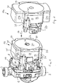
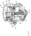
- the heating circulating pump shown has a centrifugal pump with a pump housing 1 with a suction connection 2 and a pressure connection 3 with a channel guide formed in between, which feeds the liquid coming from the suction connection 2 to a suction mouth 4 of a pump impeller 5 mounted within the pump housing 1, whose output side is connected to a pressure connection 3 leading channel connects.
- the heating circulating pump also has a motor, here a wet-running motor, the rotor 6 of which runs in a can 7 that is filled with liquid.
- the can 7 is surrounded by a stator, i. H. from the motor windings arranged circumferentially around the can 7, and a motor housing 8, which accommodates the stator.
- the rotor 6 has a central shaft 9 which extends into the pump housing 1 and carries the pump impeller 5 so that the rotational movement of the rotor 6 is transmitted to the pump impeller 5 .
- the motor housing 8 has on its side facing the pump housing 1 a flange 10 with which it is connected to the pump housing 1 and is tightly and firmly connected to the pump housing 1 via four screws 11 in the corner regions of the flange.
- the pump housing 1 and motor housing 8 are made of metal and are manufactured as cast parts.
- the motor housing 8 is designed as a metallic cast housing.
- the housing can also be formed by a cast stator, as is the case when the stator winding is cast in plastic.
- the motor housing can also be designed as a plastic injection molded part. It goes without saying that the grounding contact, which is described in detail further below, is then incorporated separately within the plastic and is electrically conductively connected to the laminated stator core and the then metallic can of the motor.
- the heating circulating pump also has a terminal box 12 which is made of plastic and is attached to the axial side of the motor housing 8 facing away from the pump housing 1 and the motor housing 8 is completely and radially, d. H. peripherally, partially overlapping.
- the space designations axial and radial listed above and below refer to the axis of rotation 13 of the rotor 6 or the pump impeller 5.
- the axial sides are the sides that run essentially perpendicular to the axis of rotation 13, whereas radial surfaces are the surfaces that are parallel to the extend axis of rotation.
- the motor housing 8 has a rounded, essentially square cross section in the flange area, whereas the remaining part of the motor housing 8, i.e. the part adjoining the terminal box 12, has an essentially circular cross section and therefore has a cylindrical peripheral surface.
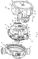
- the terminal box 12 made of plastic is fastened to the motor housing 1 by snap connections.
- the terminal box 12 has four tongues 15 extending from the side walls 14 of the terminal box towards the pump housing 1, at the end of which snap-in projections 16 are arranged laterally, which engage behind the snap-in recesses 17 in the motor housing 8, which are formed on the motor housing 8 in the region of the flange 10 .
- These snap-in recesses 17 are each formed by a step in a tubular guide 18 on the motor housing 8 pointing from the flange 10 to the terminal box 12 (see FIG 8 ).
- the tongues 15 reach the guides 18 arranged in alignment therewith, with the snap-in projections 16 moving laterally inwards by the transverse deflection of the tongues past the steps forming the snap-in recesses 17 and after Snap over the same by elastically restoring the tongues 15 outwards and thus hold the terminal box 12 on the motor housing 8.
- the terminal box 12 Seen in the direction of the axis of rotation 13, the terminal box 12 has a substantially rectangular outer contour and is recessed in the corner areas, i.e. in the area of imaginary axial extensions of the screws 11, so that the screws 11 are accessible for a tool placed on from the axial direction even when the terminal box 12 is in place are.
- corner recesses are marked 20.
- the vertical edge regions 22 are used to lead out electrical contacts, whereas the horizontal ones Edge area 21 are used for the arrangement of electronic components within the terminal box. Since pumps of the same construction can be equipped with electric motors with different motor electronics, as shown in the comparison according to the illustration 1 and 2 it becomes clear that when using different terminal boxes, which only differ in the radial extent of the horizontal edge regions 21, the internal volume of the terminal box can be varied without the electrical connections having to be changed here, neither on the motor side nor on the terminal box side.
- the extended horizontal margins in 2 are marked with 21a, the terminal box with 12a.
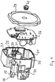
- the electrical contacts are arranged in the vertical edge areas 22, viewed in the axial direction from the terminal box 12 in the direction of the pump housing 1, the contacts 23 leading to the motor winding are in the right-hand vertical edge area 22 and those to a plug-in connection from the electrical connection are in the left-hand vertical edge area 22 contacts 24 brought out of the motor are arranged.
- These contacts 23 and 24 are shown in the sectional view according to FIG 6 to recognize. They are each made of sheet metal, ie formed as stamped parts, and are of the same design in groups, ie all contacts 23 are structurally identical to one another and all contacts 24 are structurally identical to one another.
- the contacts 23, 24 and 25 are cast tightly into the terminal box 12 made of thermoplastic material, namely the contacts 23 in the base 27 of the terminal box 12 and the contacts 24 and 25 in the base 27 or the side wall 14 adjoining it.
- the bottom 27 of the terminal box 12 is designed to be completely closed and spaced apart from the axial wall 28 of the motor housing 8 (see FIG 6 ).
- the base 27 merges into the side walls 14, which are also closed, the axial end of the side walls 14 is closed off by a cover 29, which is also closed (closed relative to the inside of the terminal box).
- the cover 29 is connected to the base body of the terminal box 12 , which consists of the base 27 and walls 14 , by means of a circumferential weld seam 30 . In this way, the interior of the terminal box is not only tight, but hermetically sealed, ie the sensitive electronics inside are reliably protected against the ingress of dust, water and gases.
- the weld 30 is formed by laser welding from the lid side.
- the cover 29 is made of a material that is permeable to the laser beam
- the base body, ie the base 27 and the side walls 14, are made of a material that is essentially impermeable to the laser beam.
- the welding takes place in such a way that the laser beam is directed from the cover side onto the end faces of the side walls 14 pointing towards the cover.
- the laser beam passes through the cover 29, which is permeable to the laser beam, to the end faces of the side walls 14, where it melts the material that also fuses with the cover material due to the effect of heat and in this way creates a hermetic welded connection between the side walls 14 and the cover 29 forms, whereby the terminal box 12 is hermetically sealed to the outside.
- the welding takes place not only in the area of the outer walls 14 but also in the area of the central recess 31, ie at a point that is otherwise extremely difficult to access for welding.
- the terminal box 12 is penetrated by a central recess 31 which runs in the axial direction, is closed by a plug 42 and is not connected to the interior of the terminal box.
- This recess 31 leads to an opening in the axial wall 28 of the motor housing 8, also closed by means of a screw, via which the free end of the shaft 9 is accessible in order to be able to turn the rotor 6 freely by hand if it is blocked.
- the screw closing this opening is designed as a type of grub screw with a hexagon socket, the hexagon socket socket being designed in such a way that the screw remains on the tool when it is removed, so that when the plug 42 is removed using a wrench, this screw is removed and then the shaft using another tool 9 can be rotated manually.
- the openings are then closed again in the reverse order.
- the recess 31 thus penetrates the terminal box 12 in the axial direction, resulting in a hermetically sealed annular space in the terminal box 12 .
- contacts 23 provided for connection to the motor winding are formed in the manner of a sleeve 32 in the base of the terminal box 12, specifically in the right-hand vertical edge region 22.
- a plug 33 is formed on the motor housing 8 and protrudes axially towards the terminal box 12 on the axial wall 28.
- the contacts 24 are led out to a socket 34 and the contacts 25 to a socket 35 with one leg.
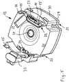
- One of the contacts 24, namely the in 7 represented, is a ground contact and is used to connect the metallic motor housing 8 to the corresponding ground connection of the sleeve 34 or to the corresponding ground connection on the circuit board 26 inside the terminal box 12 .
- the contact 24 has a plug-in part 36 on one leg, which has a slightly convex shape in the sheet metal plane, and a central longitudinal recess 37 in the plug-in direction of the plug-in part 36.
- a socket-like recess 38 Aligned with the plug-in part 36 of the grounding contact is a socket-like recess 38 in an axial elevation 39 provided on the axial wall 28 of the motor housing 8 .
- the transverse dimension of the recess 38 is slightly smaller than the transverse extent of the plug-in part 36 in the crowned area, so that when the plug-in part 36 is inserted into the recess 38, the plug-in part is deformed at least elastically, possibly also plastically, as a result of which there is intimate contact between the plug-in part 36 and the recess 38 in the motor housing 8 and thus reliable grounding is ensured.
- the recess 37 is provided so that the plug-in part 36 can also deform plastically if necessary.
- the contacts 24 and thus in particular also the grounding contact, which is intimately connected to the motor housing 8, is formed in the base 27 or in the side wall 14 in a manner that branches off into two legs (see FIG 7 ) and runs obliquely out of the terminal box towards the pump housing 1, parallel to the outer circumference of the motor housing 8, but ends at a distance in front of the flange 10 of the motor and is angled by 180° where the contacts 24 together form the sleeve 34, which serves to accommodate a connector plug at the end of a cable of an electrical supply line.
- the housing of the sleeve 34 is designed in one piece with the terminal box 12 .
- the sleeve 34 is offset from the terminal box 12 next to the motor housing 8 on the outer periphery thereof.
- a plug engaging in this sleeve 34 can be inserted in the axial direction, namely in the direction of the pump housing 1 and is then located next to the terminal box 12, namely next to the left vertical edge area 22.
- the sleeve 34 has a snap-on projection 40 which is part of a snap-on connection , the other part of which is provided on the counterpart, ie the plug.
- the sleeve 35 which receives the contacts 25, is brought out of the terminal box in a similar way, but through the side wall 14.
- the sleeve 35 formed there is shown in FIG 3 on the left vertical edge area 22 on the outer circumference of the terminal box 12, but unlike the sleeve 34 is not offset towards the motor housing 8, but is located directly next to the terminal box 12.
- the sleeve 35 has a snap-in projection 41, which in this Sleeve engaging connector against loosening secures.
- the sleeves 34 and 35 are manufactured in one piece with the terminal box 12 using the plastic injection molding process, ie by overmolding the contacts 23, 24, 25 during the manufacture of the terminal box body.
- the sleeves 34 and 35 are designed as flat sleeves in such a way that their contacts 24 and 25 are each located next to one another in a plane arranged essentially parallel to the motor housing 8 .
- This arrangement means that the radial installation space next to the motor housing 8 or terminal box 12 is comparatively small.
- the motor housing is not designed as a metallic cast housing but as a plastic housing or as a casting compound surrounding the stator, then the recess 38 in the elevation of the motor housing is provided with a contact, for example formed by a hollow-cylindrical metallic sleeve that is electrically conductive with the stator core and the metallic can 7 is connected to ensure the electrical safety of the heating circulating pump in the event that one of these components is live due to a stator defect.
Landscapes
- Engineering & Computer Science (AREA)
- Mechanical Engineering (AREA)
- General Engineering & Computer Science (AREA)
- Power Engineering (AREA)
- Microelectronics & Electronic Packaging (AREA)
- Structures Of Non-Positive Displacement Pumps (AREA)
Priority Applications (5)
| Application Number | Priority Date | Filing Date | Title |
|---|---|---|---|
| PL11002071.6T PL2500575T5 (pl) | 2011-03-12 | 2011-03-12 | Pompa obiegowa do instalacji grzewczej |
| EP11002071.6A EP2500575B2 (de) | 2011-03-12 | 2011-03-12 | Heizungsumwälzpumpe |
| PCT/EP2012/053222 WO2012123237A1 (de) | 2011-03-12 | 2012-02-24 | Heizungsumwälzpumpe |
| US14/004,547 US9546663B2 (en) | 2011-03-12 | 2012-02-24 | Heat circulation pump |
| CN201280013099.8A CN103443469B (zh) | 2011-03-12 | 2012-02-24 | 供热循环泵 |
Applications Claiming Priority (1)
| Application Number | Priority Date | Filing Date | Title |
|---|---|---|---|
| EP11002071.6A EP2500575B2 (de) | 2011-03-12 | 2011-03-12 | Heizungsumwälzpumpe |
Publications (3)
| Publication Number | Publication Date |
|---|---|
| EP2500575A1 EP2500575A1 (de) | 2012-09-19 |
| EP2500575B1 EP2500575B1 (de) | 2016-07-13 |
| EP2500575B2 true EP2500575B2 (de) | 2022-05-25 |
Family
ID=44352316
Family Applications (1)
| Application Number | Title | Priority Date | Filing Date |
|---|---|---|---|
| EP11002071.6A Active EP2500575B2 (de) | 2011-03-12 | 2011-03-12 | Heizungsumwälzpumpe |
Country Status (5)
| Country | Link |
|---|---|
| US (1) | US9546663B2 (pl) |
| EP (1) | EP2500575B2 (pl) |
| CN (1) | CN103443469B (pl) |
| PL (1) | PL2500575T5 (pl) |
| WO (1) | WO2012123237A1 (pl) |
Families Citing this family (30)
| Publication number | Priority date | Publication date | Assignee | Title |
|---|---|---|---|---|
| EP2750268B1 (de) * | 2012-12-27 | 2015-10-14 | Grundfos Holding A/S | Pumpenaggregat |
| FR3015586B1 (fr) | 2013-12-24 | 2018-04-20 | Wilo Salmson France | Procede de depannage d'une installation hydraulique domestique |
| EP4033107A1 (en) | 2014-04-24 | 2022-07-27 | Foshan Shunde Midea Washing Appliances Manufacturing Co., Ltd. | Heat pump and dishwasher comprising the same |
| US10230290B2 (en) * | 2014-09-08 | 2019-03-12 | Regal Beloit America, Inc. | Electrical machine and methods of assembling the same |
| US9985494B2 (en) | 2014-09-08 | 2018-05-29 | Regal Beloit America, Inc. | Electrical machine and controller and methods of assembling the same |
| US9982674B2 (en) | 2014-09-08 | 2018-05-29 | Regal Beloit America, Inc. | Electrical machine and methods of assembling the same |
| DE102015100502B4 (de) * | 2015-01-14 | 2023-11-30 | Cayago Tec Gmbh | Unterwasser-Antriebs-Einheit |
| DE102015213865A1 (de) * | 2015-07-22 | 2017-01-26 | Brose Fahrzeugteile GmbH & Co. Kommanditgesellschaft, Würzburg | Elektronikgehäuse |
| CN107725413B (zh) * | 2016-08-12 | 2021-07-13 | 德昌电机(深圳)有限公司 | 风机 |
| JP6518275B2 (ja) * | 2017-02-24 | 2019-05-22 | シナノケンシ株式会社 | 電動ポンプ |
| DE202017101204U1 (de) * | 2017-03-02 | 2017-03-21 | Grundfos Holding A/S | Heizungsumwälzpumpe |
| IT201700045778A1 (it) * | 2017-04-27 | 2018-10-27 | Taco Italia S R L | Circolatore di fluido con display |
| IT201700069793A1 (it) * | 2017-06-22 | 2018-12-22 | Taco Italia S R L | Circolatore di fluido con dissipatore di calore |
| IT201700103805A1 (it) * | 2017-09-18 | 2019-03-18 | Dab Pumps Spa | Assemblato di pompa con zona umida accessibile all'utente |
| JP7040093B2 (ja) * | 2018-02-13 | 2022-03-23 | 株式会社デンソー | 電動ポンプ |
| DE112019001150B4 (de) * | 2018-03-05 | 2024-10-10 | Denso Corporation | Elektrische Pumpe |
| IT201800003390A1 (it) * | 2018-03-09 | 2019-09-09 | Dab Pumps Spa | Assemblato di elettropompa centrifuga con tenuta perfezionata |
| FR3079887B1 (fr) * | 2018-04-06 | 2021-09-10 | Ksb Sas | Groupe motopompe integre |
| DE102018207356A1 (de) * | 2018-05-11 | 2019-11-14 | Brose Fahrzeugteile GmbH & Co. Kommanditgesellschaft, Würzburg | Elektromotorisches Nebenaggregat |
| DE102018207437A1 (de) * | 2018-05-14 | 2019-11-14 | Hawig Maschinenfabrik Gesellschaft mit beschränkter Haftung | Nassreinigungsvorrichtung zur Nassreinigung einer Bodenfläche |
| EP3667087B1 (en) * | 2018-12-13 | 2022-12-07 | Grundfos Holding A/S | Pump assembly |
| US12057754B2 (en) * | 2019-09-30 | 2024-08-06 | Jiangsu Leili Motor Co., Ltd. | Motor with flame-resistant terminal connecting device and lead portion |
| DE112021001825A5 (de) | 2020-03-25 | 2023-01-05 | Magna powertrain gmbh & co kg | Resolver für eine elektrische Maschine |
| CN111608896B (zh) * | 2020-05-28 | 2025-07-25 | 合肥新沪屏蔽泵有限公司 | 一种泵用控制盒 |
| US12264669B2 (en) | 2021-03-24 | 2025-04-01 | Farmchem Corp | Self-priming transfer pump with quick pump attachment/detachment |
| CN113349804A (zh) * | 2021-06-28 | 2021-09-07 | 上海大学 | 一种柔性可扩展的导电膏快速自动注射装置 |
| CN115898938A (zh) * | 2022-11-10 | 2023-04-04 | 佛山市威灵洗涤电机制造有限公司 | 转子组件、循环泵及空调器 |
| CN115540314A (zh) * | 2022-11-10 | 2022-12-30 | 佛山市威灵洗涤电机制造有限公司 | 电控总成、循环泵及空调器 |
| EP4582698A4 (en) * | 2022-11-10 | 2025-12-24 | Foshan Welling Washer Motor Mfg Co Ltd | ROTOR ASSEMBLY, CIRCULATION PUMP AND AIR CONDITIONER |
| CN115898892A (zh) * | 2022-11-10 | 2023-04-04 | 佛山市威灵洗涤电机制造有限公司 | 循环泵及空调器 |
Citations (2)
| Publication number | Priority date | Publication date | Assignee | Title |
|---|---|---|---|---|
| EP1239152A2 (en) † | 2001-03-08 | 2002-09-11 | Lucas Industries Limited | Electric motor driven hydraulic pump |
| EP2151897A1 (en) † | 2008-08-06 | 2010-02-10 | Askoll Holding S.r.l. | Connection device for a circulator for a boiler apparatus, connector for a circulator, connection socket for a circulator and circulator |
Family Cites Families (13)
| Publication number | Priority date | Publication date | Assignee | Title |
|---|---|---|---|---|
| JP2598130B2 (ja) | 1989-05-24 | 1997-04-09 | ファナック株式会社 | 一体成形コネクタを有したモータの構造 |
| US5861689A (en) | 1996-05-29 | 1999-01-19 | Emerson Electric Co. | Leadless motor construction |
| AT414064B (de) * | 2001-05-11 | 2006-08-15 | Tcg Unitech Ag | Pumpe für flüssige medien |
| DE10130117A1 (de) | 2001-06-22 | 2003-01-30 | Minebea Co Ltd | Gehäusedeckel für einen Elektromotor, insbesondere für einen elektronisch kommutierten Gleichstrommotor |
| EP1437819B1 (en) | 2003-01-10 | 2008-11-05 | Askoll Holding S.r.l. | Permanent magnet synchronous electric motor for circulation pumps of heating and conditioning systems |
| DE602004023556D1 (de) * | 2003-05-28 | 2009-11-26 | Aisin Seiki | Elektrisch angetriebene Pumpe |
| DE102004030721B3 (de) | 2004-06-25 | 2005-10-13 | Richard Halm | Elektrische Maschine, insbesondere Spaltrohrmotor für eine Umwälzpumpe |
| GB2418072B (en) | 2004-09-14 | 2008-05-07 | Dana Automotive Ltd | Pump assembly |
| CN100543294C (zh) * | 2005-03-28 | 2009-09-23 | 于佳衣 | 一种单腔永磁转子泵循环预热器及其装配方法 |
| JP2008128076A (ja) * | 2006-11-20 | 2008-06-05 | Aisan Ind Co Ltd | 流体ポンプ |
| ATE505651T1 (de) * | 2007-01-18 | 2011-04-15 | Grundfos Management As | Pumpenaggregat |
| DE102007022070A1 (de) * | 2007-05-08 | 2008-11-13 | Wilo Ag | Elektromotor |
| EP2072828B1 (de) | 2007-12-17 | 2018-03-28 | Grundfos Management A/S | Nasslaufkreiselpumpe |
-
2011
- 2011-03-12 EP EP11002071.6A patent/EP2500575B2/de active Active
- 2011-03-12 PL PL11002071.6T patent/PL2500575T5/pl unknown
-
2012
- 2012-02-24 US US14/004,547 patent/US9546663B2/en active Active
- 2012-02-24 CN CN201280013099.8A patent/CN103443469B/zh active Active
- 2012-02-24 WO PCT/EP2012/053222 patent/WO2012123237A1/de not_active Ceased
Patent Citations (2)
| Publication number | Priority date | Publication date | Assignee | Title |
|---|---|---|---|---|
| EP1239152A2 (en) † | 2001-03-08 | 2002-09-11 | Lucas Industries Limited | Electric motor driven hydraulic pump |
| EP2151897A1 (en) † | 2008-08-06 | 2010-02-10 | Askoll Holding S.r.l. | Connection device for a circulator for a boiler apparatus, connector for a circulator, connection socket for a circulator and circulator |
Also Published As
| Publication number | Publication date |
|---|---|
| WO2012123237A1 (de) | 2012-09-20 |
| PL2500575T5 (pl) | 2022-10-17 |
| EP2500575B1 (de) | 2016-07-13 |
| EP2500575A1 (de) | 2012-09-19 |
| CN103443469B (zh) | 2016-08-24 |
| US20130343935A1 (en) | 2013-12-26 |
| US9546663B2 (en) | 2017-01-17 |
| PL2500575T3 (pl) | 2017-08-31 |
| CN103443469A (zh) | 2013-12-11 |
Similar Documents
| Publication | Publication Date | Title |
|---|---|---|
| EP2500575B2 (de) | Heizungsumwälzpumpe | |
| EP2500576B1 (de) | Heizungsumwälzpumpe | |
| EP2500574B1 (de) | Heizungsumwälzpumpe | |
| EP2500577B1 (de) | Heizungsumwälzpumpe | |
| EP2043234B1 (de) | Elektromotor | |
| EP2320092B1 (de) | Pumpenaggregat | |
| EP2500578B1 (de) | Heizungsumwälzpumpe | |
| EP2607707B2 (de) | Elektromotor | |
| EP1404008A2 (de) | Elektromotor mit schraubenloser Steckmontage | |
| WO2017102630A1 (de) | Elektrische antriebseinheit mit einem gehäuse | |
| EP2750266A1 (de) | Pumpenaggregat | |
| DE102016204954A1 (de) | Elektrische Maschine sowie Verfahren zum Herstellen einer elektrischen Maschine | |
| EP2607709A1 (de) | Elektromotor | |
| DE102019005171A1 (de) | Elektromotor, insbesondere Außenläufermotor | |
| EP2607708B1 (de) | Elektromotor | |
| DE202013012219U1 (de) | Elektromotor, insbesondere Kühlerlüftermotor | |
| EP2750268A1 (de) | Pumpenaggregat | |
| EP3940242A1 (de) | Strömungsmaschine mit in einer vergussmasse eingebetteten anschlussleitungen | |
| DE102005012620A1 (de) | Elektrischer Antrieb | |
| EP3369933A1 (de) | Heizungsumwälzpumpe | |
| EP3391509A1 (de) | Elektromotor | |
| WO2020089011A1 (de) | Gehäusedeckel für eine elektrische maschine und verfahren zum herstellen eines gehäusedeckels | |
| DE202005004435U1 (de) | Elektrischer Antrieb |
Legal Events
| Date | Code | Title | Description |
|---|---|---|---|
| PUAI | Public reference made under article 153(3) epc to a published international application that has entered the european phase |
Free format text: ORIGINAL CODE: 0009012 |
|
| AK | Designated contracting states |
Kind code of ref document: A1 Designated state(s): AL AT BE BG CH CY CZ DE DK EE ES FI FR GB GR HR HU IE IS IT LI LT LU LV MC MK MT NL NO PL PT RO RS SE SI SK SM TR |
|
| AX | Request for extension of the european patent |
Extension state: BA ME |
|
| 17P | Request for examination filed |
Effective date: 20130318 |
|
| GRAP | Despatch of communication of intention to grant a patent |
Free format text: ORIGINAL CODE: EPIDOSNIGR1 |
|
| INTG | Intention to grant announced |
Effective date: 20160210 |
|
| GRAS | Grant fee paid |
Free format text: ORIGINAL CODE: EPIDOSNIGR3 |
|
| GRAA | (expected) grant |
Free format text: ORIGINAL CODE: 0009210 |
|
| AK | Designated contracting states |
Kind code of ref document: B1 Designated state(s): AL AT BE BG CH CY CZ DE DK EE ES FI FR GB GR HR HU IE IS IT LI LT LU LV MC MK MT NL NO PL PT RO RS SE SI SK SM TR |
|
| REG | Reference to a national code |
Ref country code: GB Ref legal event code: FG4D Free format text: NOT ENGLISH |
|
| REG | Reference to a national code |
Ref country code: AT Ref legal event code: REF Ref document number: 812582 Country of ref document: AT Kind code of ref document: T Effective date: 20160715 Ref country code: CH Ref legal event code: EP |
|
| REG | Reference to a national code |
Ref country code: IE Ref legal event code: FG4D Free format text: LANGUAGE OF EP DOCUMENT: GERMAN |
|
| REG | Reference to a national code |
Ref country code: DE Ref legal event code: R096 Ref document number: 502011010131 Country of ref document: DE |
|
| REG | Reference to a national code |
Ref country code: LT Ref legal event code: MG4D |
|
| REG | Reference to a national code |
Ref country code: NL Ref legal event code: MP Effective date: 20160713 |
|
| REG | Reference to a national code |
Ref country code: FR Ref legal event code: PLFP Year of fee payment: 7 |
|
| PG25 | Lapsed in a contracting state [announced via postgrant information from national office to epo] |
Ref country code: NO Free format text: LAPSE BECAUSE OF FAILURE TO SUBMIT A TRANSLATION OF THE DESCRIPTION OR TO PAY THE FEE WITHIN THE PRESCRIBED TIME-LIMIT Effective date: 20161013 Ref country code: LT Free format text: LAPSE BECAUSE OF FAILURE TO SUBMIT A TRANSLATION OF THE DESCRIPTION OR TO PAY THE FEE WITHIN THE PRESCRIBED TIME-LIMIT Effective date: 20160713 Ref country code: HR Free format text: LAPSE BECAUSE OF FAILURE TO SUBMIT A TRANSLATION OF THE DESCRIPTION OR TO PAY THE FEE WITHIN THE PRESCRIBED TIME-LIMIT Effective date: 20160713 Ref country code: NL Free format text: LAPSE BECAUSE OF FAILURE TO SUBMIT A TRANSLATION OF THE DESCRIPTION OR TO PAY THE FEE WITHIN THE PRESCRIBED TIME-LIMIT Effective date: 20160713 Ref country code: FI Free format text: LAPSE BECAUSE OF FAILURE TO SUBMIT A TRANSLATION OF THE DESCRIPTION OR TO PAY THE FEE WITHIN THE PRESCRIBED TIME-LIMIT Effective date: 20160713 Ref country code: IS Free format text: LAPSE BECAUSE OF FAILURE TO SUBMIT A TRANSLATION OF THE DESCRIPTION OR TO PAY THE FEE WITHIN THE PRESCRIBED TIME-LIMIT Effective date: 20161113 Ref country code: RS Free format text: LAPSE BECAUSE OF FAILURE TO SUBMIT A TRANSLATION OF THE DESCRIPTION OR TO PAY THE FEE WITHIN THE PRESCRIBED TIME-LIMIT Effective date: 20160713 |
|
| PG25 | Lapsed in a contracting state [announced via postgrant information from national office to epo] |
Ref country code: ES Free format text: LAPSE BECAUSE OF FAILURE TO SUBMIT A TRANSLATION OF THE DESCRIPTION OR TO PAY THE FEE WITHIN THE PRESCRIBED TIME-LIMIT Effective date: 20160713 Ref country code: PT Free format text: LAPSE BECAUSE OF FAILURE TO SUBMIT A TRANSLATION OF THE DESCRIPTION OR TO PAY THE FEE WITHIN THE PRESCRIBED TIME-LIMIT Effective date: 20161114 Ref country code: LV Free format text: LAPSE BECAUSE OF FAILURE TO SUBMIT A TRANSLATION OF THE DESCRIPTION OR TO PAY THE FEE WITHIN THE PRESCRIBED TIME-LIMIT Effective date: 20160713 Ref country code: SE Free format text: LAPSE BECAUSE OF FAILURE TO SUBMIT A TRANSLATION OF THE DESCRIPTION OR TO PAY THE FEE WITHIN THE PRESCRIBED TIME-LIMIT Effective date: 20160713 Ref country code: GR Free format text: LAPSE BECAUSE OF FAILURE TO SUBMIT A TRANSLATION OF THE DESCRIPTION OR TO PAY THE FEE WITHIN THE PRESCRIBED TIME-LIMIT Effective date: 20161014 |
|
| REG | Reference to a national code |
Ref country code: DE Ref legal event code: R026 Ref document number: 502011010131 Country of ref document: DE |
|
| PLBI | Opposition filed |
Free format text: ORIGINAL CODE: 0009260 |
|
| 26 | Opposition filed |
Opponent name: TACO ITALIA S.R.L. Effective date: 20170309 |
|
| PG25 | Lapsed in a contracting state [announced via postgrant information from national office to epo] |
Ref country code: RO Free format text: LAPSE BECAUSE OF FAILURE TO SUBMIT A TRANSLATION OF THE DESCRIPTION OR TO PAY THE FEE WITHIN THE PRESCRIBED TIME-LIMIT Effective date: 20160713 Ref country code: EE Free format text: LAPSE BECAUSE OF FAILURE TO SUBMIT A TRANSLATION OF THE DESCRIPTION OR TO PAY THE FEE WITHIN THE PRESCRIBED TIME-LIMIT Effective date: 20160713 |
|
| PLAX | Notice of opposition and request to file observation + time limit sent |
Free format text: ORIGINAL CODE: EPIDOSNOBS2 |
|
| PG25 | Lapsed in a contracting state [announced via postgrant information from national office to epo] |
Ref country code: BG Free format text: LAPSE BECAUSE OF FAILURE TO SUBMIT A TRANSLATION OF THE DESCRIPTION OR TO PAY THE FEE WITHIN THE PRESCRIBED TIME-LIMIT Effective date: 20161013 Ref country code: CZ Free format text: LAPSE BECAUSE OF FAILURE TO SUBMIT A TRANSLATION OF THE DESCRIPTION OR TO PAY THE FEE WITHIN THE PRESCRIBED TIME-LIMIT Effective date: 20160713 Ref country code: SK Free format text: LAPSE BECAUSE OF FAILURE TO SUBMIT A TRANSLATION OF THE DESCRIPTION OR TO PAY THE FEE WITHIN THE PRESCRIBED TIME-LIMIT Effective date: 20160713 Ref country code: DK Free format text: LAPSE BECAUSE OF FAILURE TO SUBMIT A TRANSLATION OF THE DESCRIPTION OR TO PAY THE FEE WITHIN THE PRESCRIBED TIME-LIMIT Effective date: 20160713 Ref country code: SM Free format text: LAPSE BECAUSE OF FAILURE TO SUBMIT A TRANSLATION OF THE DESCRIPTION OR TO PAY THE FEE WITHIN THE PRESCRIBED TIME-LIMIT Effective date: 20160713 |
|
| PG25 | Lapsed in a contracting state [announced via postgrant information from national office to epo] |
Ref country code: SI Free format text: LAPSE BECAUSE OF FAILURE TO SUBMIT A TRANSLATION OF THE DESCRIPTION OR TO PAY THE FEE WITHIN THE PRESCRIBED TIME-LIMIT Effective date: 20160713 |
|
| PLBB | Reply of patent proprietor to notice(s) of opposition received |
Free format text: ORIGINAL CODE: EPIDOSNOBS3 |
|
| REG | Reference to a national code |
Ref country code: CH Ref legal event code: PL |
|
| PG25 | Lapsed in a contracting state [announced via postgrant information from national office to epo] |
Ref country code: MC Free format text: LAPSE BECAUSE OF FAILURE TO SUBMIT A TRANSLATION OF THE DESCRIPTION OR TO PAY THE FEE WITHIN THE PRESCRIBED TIME-LIMIT Effective date: 20160713 |
|
| REG | Reference to a national code |
Ref country code: IE Ref legal event code: MM4A |
|
| REG | Reference to a national code |
Ref country code: FR Ref legal event code: PLFP Year of fee payment: 8 |
|
| PG25 | Lapsed in a contracting state [announced via postgrant information from national office to epo] |
Ref country code: LU Free format text: LAPSE BECAUSE OF NON-PAYMENT OF DUE FEES Effective date: 20170312 |
|
| PG25 | Lapsed in a contracting state [announced via postgrant information from national office to epo] |
Ref country code: IE Free format text: LAPSE BECAUSE OF NON-PAYMENT OF DUE FEES Effective date: 20170312 Ref country code: CH Free format text: LAPSE BECAUSE OF NON-PAYMENT OF DUE FEES Effective date: 20170331 Ref country code: LI Free format text: LAPSE BECAUSE OF NON-PAYMENT OF DUE FEES Effective date: 20170331 |
|
| REG | Reference to a national code |
Ref country code: BE Ref legal event code: MM Effective date: 20170331 |
|
| REG | Reference to a national code |
Ref country code: AT Ref legal event code: MM01 Ref document number: 812582 Country of ref document: AT Kind code of ref document: T Effective date: 20170312 |
|
| PG25 | Lapsed in a contracting state [announced via postgrant information from national office to epo] |
Ref country code: BE Free format text: LAPSE BECAUSE OF NON-PAYMENT OF DUE FEES Effective date: 20170331 |
|
| PLCK | Communication despatched that opposition was rejected |
Free format text: ORIGINAL CODE: EPIDOSNREJ1 |
|
| STAA | Information on the status of an ep patent application or granted ep patent |
Free format text: STATUS: THE PATENT HAS BEEN GRANTED |
|
| PG25 | Lapsed in a contracting state [announced via postgrant information from national office to epo] |
Ref country code: AT Free format text: LAPSE BECAUSE OF NON-PAYMENT OF DUE FEES Effective date: 20170312 |
|
| PG25 | Lapsed in a contracting state [announced via postgrant information from national office to epo] |
Ref country code: MT Free format text: LAPSE BECAUSE OF FAILURE TO SUBMIT A TRANSLATION OF THE DESCRIPTION OR TO PAY THE FEE WITHIN THE PRESCRIBED TIME-LIMIT Effective date: 20160713 |
|
| APBM | Appeal reference recorded |
Free format text: ORIGINAL CODE: EPIDOSNREFNO |
|
| APBP | Date of receipt of notice of appeal recorded |
Free format text: ORIGINAL CODE: EPIDOSNNOA2O |
|
| APAH | Appeal reference modified |
Free format text: ORIGINAL CODE: EPIDOSCREFNO |
|
| PG25 | Lapsed in a contracting state [announced via postgrant information from national office to epo] |
Ref country code: AL Free format text: LAPSE BECAUSE OF FAILURE TO SUBMIT A TRANSLATION OF THE DESCRIPTION OR TO PAY THE FEE WITHIN THE PRESCRIBED TIME-LIMIT Effective date: 20160713 |
|
| APBQ | Date of receipt of statement of grounds of appeal recorded |
Free format text: ORIGINAL CODE: EPIDOSNNOA3O |
|
| PG25 | Lapsed in a contracting state [announced via postgrant information from national office to epo] |
Ref country code: HU Free format text: LAPSE BECAUSE OF FAILURE TO SUBMIT A TRANSLATION OF THE DESCRIPTION OR TO PAY THE FEE WITHIN THE PRESCRIBED TIME-LIMIT; INVALID AB INITIO Effective date: 20110312 |
|
| PG25 | Lapsed in a contracting state [announced via postgrant information from national office to epo] |
Ref country code: CY Free format text: LAPSE BECAUSE OF NON-PAYMENT OF DUE FEES Effective date: 20160713 |
|
| PG25 | Lapsed in a contracting state [announced via postgrant information from national office to epo] |
Ref country code: MK Free format text: LAPSE BECAUSE OF FAILURE TO SUBMIT A TRANSLATION OF THE DESCRIPTION OR TO PAY THE FEE WITHIN THE PRESCRIBED TIME-LIMIT Effective date: 20160713 |
|
| PLAB | Opposition data, opponent's data or that of the opponent's representative modified |
Free format text: ORIGINAL CODE: 0009299OPPO |
|
| R26 | Opposition filed (corrected) |
Opponent name: TACO ITALIA S.R.L. Effective date: 20170309 |
|
| APBU | Appeal procedure closed |
Free format text: ORIGINAL CODE: EPIDOSNNOA9O |
|
| PUAH | Patent maintained in amended form |
Free format text: ORIGINAL CODE: 0009272 |
|
| STAA | Information on the status of an ep patent application or granted ep patent |
Free format text: STATUS: PATENT MAINTAINED AS AMENDED |
|
| 27A | Patent maintained in amended form |
Effective date: 20220525 |
|
| AK | Designated contracting states |
Kind code of ref document: B2 Designated state(s): AL AT BE BG CH CY CZ DE DK EE ES FI FR GB GR HR HU IE IS IT LI LT LU LV MC MK MT NL NO PL PT RO RS SE SI SK SM TR |
|
| REG | Reference to a national code |
Ref country code: DE Ref legal event code: R102 Ref document number: 502011010131 Country of ref document: DE |
|
| REG | Reference to a national code |
Ref country code: DE Ref legal event code: R082 Ref document number: 502011010131 Country of ref document: DE Ref country code: DE Ref legal event code: R082 Ref document number: 502011010131 Country of ref document: DE Representative=s name: MITSCHERLICH, PATENT- UND RECHTSANWAELTE PARTM, DE Ref country code: DE Ref legal event code: R082 Ref document number: 502011010131 Country of ref document: DE Representative=s name: MITSCHERLICH PARTMBB, DE |
|
| REG | Reference to a national code |
Ref country code: DE Ref legal event code: R082 Ref document number: 502011010131 Country of ref document: DE Representative=s name: MITSCHERLICH, PATENT- UND RECHTSANWAELTE PARTM, DE Ref country code: DE Ref legal event code: R082 Ref document number: 502011010131 Country of ref document: DE Representative=s name: MITSCHERLICH PARTMBB, DE |
|
| REG | Reference to a national code |
Ref country code: DE Ref legal event code: R039 Ref document number: 502011010131 Country of ref document: DE Ref country code: DE Ref legal event code: R008 Ref document number: 502011010131 Country of ref document: DE |
|
| REG | Reference to a national code |
Ref country code: DE Ref legal event code: R040 Ref document number: 502011010131 Country of ref document: DE |
|
| PGFP | Annual fee paid to national office [announced via postgrant information from national office to epo] |
Ref country code: GB Payment date: 20260324 Year of fee payment: 16 |
|
| PGFP | Annual fee paid to national office [announced via postgrant information from national office to epo] |
Ref country code: DE Payment date: 20260319 Year of fee payment: 16 |
|
| PGFP | Annual fee paid to national office [announced via postgrant information from national office to epo] |
Ref country code: IT Payment date: 20260324 Year of fee payment: 16 |
|
| PGFP | Annual fee paid to national office [announced via postgrant information from national office to epo] |
Ref country code: FR Payment date: 20260320 Year of fee payment: 16 |
|
| PGFP | Annual fee paid to national office [announced via postgrant information from national office to epo] |
Ref country code: TR Payment date: 20260304 Year of fee payment: 16 |
|
| PGFP | Annual fee paid to national office [announced via postgrant information from national office to epo] |
Ref country code: PL Payment date: 20260226 Year of fee payment: 16 |