EP2500478B1 - Verbindungsmittel mit einem Verbindungskopf - Google Patents
Verbindungsmittel mit einem Verbindungskopf Download PDFInfo
- Publication number
- EP2500478B1 EP2500478B1 EP12159664.7A EP12159664A EP2500478B1 EP 2500478 B1 EP2500478 B1 EP 2500478B1 EP 12159664 A EP12159664 A EP 12159664A EP 2500478 B1 EP2500478 B1 EP 2500478B1
- Authority
- EP
- European Patent Office
- Prior art keywords
- fastening
- head
- insulating body
- fastening means
- auxiliary connecting
- Prior art date
- Legal status (The legal status is an assumption and is not a legal conclusion. Google has not performed a legal analysis and makes no representation as to the accuracy of the status listed.)
- Not-in-force
Links
- 239000000463 material Substances 0.000 claims description 15
- 229920005830 Polyurethane Foam Polymers 0.000 claims description 4
- 230000003213 activating effect Effects 0.000 claims description 4
- 238000004873 anchoring Methods 0.000 claims description 4
- 230000005540 biological transmission Effects 0.000 claims description 4
- 238000005553 drilling Methods 0.000 claims description 4
- 239000011496 polyurethane foam Substances 0.000 claims description 4
- 238000004026 adhesive bonding Methods 0.000 claims description 2
- 239000007769 metal material Substances 0.000 claims description 2
- 238000010079 rubber tapping Methods 0.000 claims description 2
- 238000003466 welding Methods 0.000 claims description 2
- 239000004033 plastic Substances 0.000 description 6
- 229920003023 plastic Polymers 0.000 description 6
- 230000000087 stabilizing effect Effects 0.000 description 5
- 239000002991 molded plastic Substances 0.000 description 4
- 230000000694 effects Effects 0.000 description 3
- 239000011810 insulating material Substances 0.000 description 3
- 238000009413 insulation Methods 0.000 description 3
- 239000007787 solid Substances 0.000 description 3
- 229920000049 Carbon (fiber) Polymers 0.000 description 2
- 230000004913 activation Effects 0.000 description 2
- 239000004917 carbon fiber Substances 0.000 description 2
- 239000000919 ceramic Substances 0.000 description 2
- 230000007613 environmental effect Effects 0.000 description 2
- 239000011152 fibreglass Substances 0.000 description 2
- 239000006260 foam Substances 0.000 description 2
- 239000011521 glass Substances 0.000 description 2
- VNWKTOKETHGBQD-UHFFFAOYSA-N methane Chemical compound C VNWKTOKETHGBQD-UHFFFAOYSA-N 0.000 description 2
- 239000012811 non-conductive material Substances 0.000 description 2
- 229920001296 polysiloxane Polymers 0.000 description 2
- 230000002787 reinforcement Effects 0.000 description 2
- OKTJSMMVPCPJKN-UHFFFAOYSA-N Carbon Chemical compound [C] OKTJSMMVPCPJKN-UHFFFAOYSA-N 0.000 description 1
- 230000032683 aging Effects 0.000 description 1
- 239000002131 composite material Substances 0.000 description 1
- 238000010276 construction Methods 0.000 description 1
- 238000001746 injection moulding Methods 0.000 description 1
- 238000004519 manufacturing process Methods 0.000 description 1
- 239000002184 metal Substances 0.000 description 1
Images


Classifications
-
- E—FIXED CONSTRUCTIONS
- E04—BUILDING
- E04B—GENERAL BUILDING CONSTRUCTIONS; WALLS, e.g. PARTITIONS; ROOFS; FLOORS; CEILINGS; INSULATION OR OTHER PROTECTION OF BUILDINGS
- E04B1/00—Constructions in general; Structures which are not restricted either to walls, e.g. partitions, or floors or ceilings or roofs
- E04B1/62—Insulation or other protection; Elements or use of specified material therefor
- E04B1/74—Heat, sound or noise insulation, absorption, or reflection; Other building methods affording favourable thermal or acoustical conditions, e.g. accumulating of heat within walls
- E04B1/76—Heat, sound or noise insulation, absorption, or reflection; Other building methods affording favourable thermal or acoustical conditions, e.g. accumulating of heat within walls specifically with respect to heat only
- E04B1/762—Exterior insulation of exterior walls
- E04B1/7629—Details of the mechanical connection of the insulation to the wall
Definitions
- the invention relates to a connecting means with a connecting head according to the type specified in the preamble of claim 1.
- connecting means are known in different designs and serve to connect a component to another component or to attach a component to a fixed structure.
- the connecting means on a connection head, which is provided with a support surface. This bearing surface is in the assembled state directly or indirectly to the component.
- the force for the activation of the connecting means in particular by means of a tool introduced.
- the connecting means is designed in the form of a screw, the tool is attached to the connecting head and the screw is screwed into a solid structure for connecting a component in, for example, a threaded bore.
- the screw in this case has an external thread, but are also conceivable other connecting body having other radially applied projections or other applied projection than the external thread.
- connection head and the connection body are formed integrally with the same material.
- the screw usually passes through the component to be fastened to the support structure and the screw head presses this component indirectly, e.g. using a washer, or directly against the support structure.
- connecting means comes in the assembled state to heat / cold bridges, in particular when the connecting means passes through a thermal insulation and a body is to be arranged on the thermal insulation. This is the case for example in houses, which are thermally insulated and on the outer facade canopies, awning fastenings, railings and the like are fastened with connecting means, which then engage in the solid support structure of the house in the form of masonry.
- a connecting means is introduced in the form of a screw in an injection-molded plastic from one side and from the other side a connecting means in the form of a threaded rod. Both connecting means are thermally decoupled from each other by the injection molding plastic.
- a detachable sleeve presses the injection-molded plastic in each case onto the part of the connecting body of the connecting means introduced into the injection-molded plastic.
- a detachable unit of two connecting means is provided, which can also be disassembled again and is fixed by the sleeve in an assembled state.
- This embodiment has the disadvantage that it is very expensive to manufacture and in the assembly. Many parts need to be connected together to make a connection. Moreover, it is possible that in the event of a failure of the sleeve and a breakage of the injection-molded plastic, the one connecting means can no longer be deactivated, ie dismantled, without further ado. The stability of the connection is no longer given.
- connection head emerges, which has a contact surface for direct or indirect contact with a first body.
- a force for activating the connection means in particular with a tool, is introduced via the connection head.
- a connecting body is formed with projecting from this connecting body radially projection or projections for anchoring in at least one second body.
- the connection head is fixedly connected to the connecting body via an insulating body and thermally decoupled from each other by the insulating body.
- the insulating body is firmly connected to the connecting head and the connecting body, whereby a power transmission for activating the connecting means between the connecting head and connecting body is made possible.
- From the DE 201 07 906 U1 is a façade anchor for fastening and anchoring loads on facades of thermal composite systems, which has an insulating material made of rigid polyurethane foam.
- the invention has the object of providing a connecting means according to the type specified in the preamble of claim 1 further such that while avoiding the disadvantages mentioned a simple assembly and disassembly is possible. In particular, this should also be possible with damage to the element, which ensures the thermal decoupling.
- the invention is based on the finding that a thermally decoupled connection means is provided from the outset, in which the connecting head facing a body on one side and the connecting body engaging in another body are thermally decoupled from each other and form an insoluble structural unit.
- the thermal decoupling takes place by an insulating body, wherein stop means are provided which allow assembly, disassembly and maintain the connection when the insulating body is damaged.
- a problem for the strength of the connecting means according to the invention may be the insulating body in certain applications, because this usually has lower strength values than the connecting head or the connecting body. In addition, this is more susceptible to environmental influences.
- auxiliary stop means are provided in the insulating body, which are spaced from each other, wherein in each case an auxiliary stop means with the connecting head and another auxiliary stop means is connected to the connecting body and only upon damage of the insulating body and to move towards each other due to an applied force the Auxiliary stop means to each other to the plant come and take effect.
- the insulating body is in the connecting means is a weak point, which can come due to overuse but also by environmental influences, such as sunlight and the resulting aging of the material to damage the insulating body.
- the auxiliary stop means are provided. In a simple way can be maintained by the auxiliary stop means and damage to the insulating body, the connection function and carried out an assembly and disassembly.
- first auxiliary stop means are provided in Dämmêtrajis which are spaced from each other, wherein in each case a first auxiliary stop means with the connecting head and a further first auxiliary stop means is connected to the connecting body and only when damaging the insulating body and move towards each other due to an applied force, the first auxiliary stop means to each other to the plant and take effect.
- the connecting means as such remains werkisam remains.
- force can be transmitted from the connection head to the connection body at least in a longitudinal direction.
- the first auxiliary stop means are effective in both longitudinal directions of the connection means so as to be able to transmit force in both directions.
- the axis of rotation is formed by the longitudinal axis of the connecting body and / or connecting means.
- the stop means in the body are designed so that the largest possible surface is given for mutual contact.
- a coiled, stepped and / or meandering design of the auxiliary stop means is advantageous.
- the insulating body may be a foam, which is provided with gas inclusions in each case a cavity, in particular polyurethane foam include, preferably, this may be formed as a highly insulating DämmMech.
- connection head is connected to other components or is connectable, for example a plate.
- the connecting means is designed so that an activation by screwing, wrapping, gluing, locking, riveting, friction welding, jamming and / or the like is made possible.
- the connecting body and the connecting head made of metallic material, in particular, both parts may be formed of the same material or of different materials.
- the material of the insulating body can come in terms of the desired load to its limits. According to one embodiment of the invention, therefore, at least thermally or thermally and electrically inferior or thermally or thermally and electrically nonconductive materials may be introduced in areas where in use spikes occur, such as carbon fiber posts, fiberglass profiles, ceramics, glass, silicone and the like ,
- the insulating body thus comprises such insulating reinforcements as well as an insulating material.
- this is designed as a screw, wherein the connecting head is formed by a screw head and the connecting body by a threaded body.
- the threaded body may have a self-tapping thread and / or be provided with a self-drilling tip.
- the threaded body can be provided with a, in particular centric, bore with internal thread and / or with an external thread.
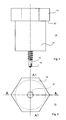
- a first embodiment of a connecting means in the form of a screw 10 is shown.
- the screw 10 consists of a threaded body 12 and a screw head 14.
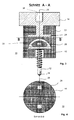
- the threaded body 12 and the screw head 14 are connected via an insulating body 16 with each other.
- the screw head 14 is formed as a hexagon.
- the screw 10 is rotated by means of a wrench into a correspondingly stepped bore in and out.
- the threaded body 12 engages with its self-drilling tip 18 in a support structure, such as a house wall or the like.
- a second bore which is arranged concentrically to the first bore in the support structure, engages the insulating body 16 of the screw 10 a.
- the underside of the screw head 14 has a support surface 20.
- a component to be fixed is pressed against the support structure and thus fixed.
- the screw 10 engages with the insulating body 16 and the threaded body 12, the component and engages in the support structure.
- the screw head 14 is provided with a cylindrical pin 22 to which a first transverse plate 24 is attached.
- the cylindrical pin 22 projects into the insulating body 16, extends concentrically to the longitudinal axis 26 of the screw 10.
- the first transverse plate 24 extends transversely to the longitudinal axis 26 of the screw 10.
- This first stop ring 28 passes through a second stop ring 30, which is fixedly connected to a second transverse plate 32.
- the second transverse plate 32 is fixedly connected to the threaded body 12.
- the first and second stop ring 28, 30 pass through each other so that they do not touch.
- the screw 10 may continue to be actuated, namely the screw 10 in a supporting structure in or out to be rotated. This is ensured by the interlocking first and second stop rings 28, 30.
- the intermediate spaces are all filled with the material of the insulating body. This consists for example of rigid polyurethane foam. But it can also consist of other foams with gas inclusions. Even have the quality "high insulation”.
- Fig. 7 to 9 is shown a further embodiment of the invention, however, for the same parts, the same reference numerals as in the first embodiment are used.
- the screw head 14 of the screw 10 according to the Fig. 7 to 9 In the present case, not the screw head 14 acts directly on the other component, but the insulating body 16.
- the screw head 14 acts on the insulating body 16 on the other, not shown here component.
- the threaded body 12 passes through the further component and is anchored in a solid support structure.
- the insulating body 16 presses against the surface of the further component and above against the support structure via the screw head 14.
- the screw head 14 is octagonal, so that the screw 10 can be actuated via a correspondingly formed wrench.
- a plastic ring 36 is introduced below the second transverse plate 32.
- the plastic ring 36 is formed correspondingly engages spaced around the threaded body 12 and has a lateral extent corresponding to the second transverse plate 32 and is arranged concentrically to the longitudinal side 26.
- the plastic ring 36 terminates at its tip 18 of the threaded body 12 facing side flush with the insulating body 16.
- the screw 10 is formed as a rotationally symmetrical part in the region of the insulating body 16 with the exception of the two stop rings 28, 30.
- the stop rings 28, 30 have a rectangular cross-sectional shape and are fixedly connected to the respective associated transverse plate 24, 32. Between the stop rings 28, 30 and the transverse plates 24, 32 stabilizing elements 34 are introduced, which are not directly connected to the stop ring 24, 32 or the transverse plate 24, 32, but are held by the material of the insulating body 16 in position. Depending on the design and arrangement, the stabilizing elements 34 increase the compressive strength and / or tensile strength of the insulating body 16.
- the stabilizing element 34 consists at least of thermally or thermally and electrically minder advicedem or thermally or thermally and electrically non-conductive material, such as carbon fiber pencils, fiberglass profiles, ceramics, glass, silicone and the like.
- the insulating body 16 thus includes such insulating reinforcements in the form of stabilizing elements 34 as well as an insulating material. From a corresponding material and the plastic ring may be formed.
- the screw head 14, the cylindrical pin 22, the first transverse plate 24 and the first stop ring 28 are integrally formed of the same material.
- the same materials, in particular metal have been used for both parts. It is also possible to use different materials, in particular with regard to the strength, thermal conductivity u. ä.
- the screw head 14 of both embodiments has a threaded bore 38.
- About the threaded bore 38 of the screw head 14 can be connected to other elements and components.
- the stop ring 28 and 30 serve both as a stop in the direction of the longitudinal axis 26 and as a stop in a rotational movement towards each other. This is important to maintain the function of the screw 10 even with such damage to the insulating body 16 when the insulating body can no longer transmit forces in the longitudinal direction and / or in the direction of rotation.
Landscapes
- Physics & Mathematics (AREA)
- Engineering & Computer Science (AREA)
- Architecture (AREA)
- Acoustics & Sound (AREA)
- Electromagnetism (AREA)
- Civil Engineering (AREA)
- Structural Engineering (AREA)
- Connection Of Plates (AREA)
Priority Applications (1)
| Application Number | Priority Date | Filing Date | Title |
|---|---|---|---|
| PL12159664T PL2500478T3 (pl) | 2011-03-17 | 2012-03-15 | Środek złączny z głowicą złączną |
Applications Claiming Priority (1)
| Application Number | Priority Date | Filing Date | Title |
|---|---|---|---|
| DE102011001376A DE102011001376A1 (de) | 2011-03-17 | 2011-03-17 | Verbindungsmittel mit einem Verbindungskopf |
Publications (2)
| Publication Number | Publication Date |
|---|---|
| EP2500478A1 EP2500478A1 (de) | 2012-09-19 |
| EP2500478B1 true EP2500478B1 (de) | 2014-07-09 |
Family
ID=45894216
Family Applications (1)
| Application Number | Title | Priority Date | Filing Date |
|---|---|---|---|
| EP12159664.7A Not-in-force EP2500478B1 (de) | 2011-03-17 | 2012-03-15 | Verbindungsmittel mit einem Verbindungskopf |
Country Status (3)
| Country | Link |
|---|---|
| EP (1) | EP2500478B1 (pl) |
| DE (1) | DE102011001376A1 (pl) |
| PL (1) | PL2500478T3 (pl) |
Family Cites Families (5)
| Publication number | Priority date | Publication date | Assignee | Title |
|---|---|---|---|---|
| DE3132201A1 (de) * | 1981-08-14 | 1983-03-03 | Hansdieter 6141 Einhausen Eberle | Verfahren und vorrichtung zur anbringung von eine vorsatzschalung bildenden platten an waenden |
| DE20107906U1 (de) * | 2001-05-10 | 2001-09-06 | Puren-Schaumstoff GmbH, 88662 Überlingen | Fassadenanker |
| DE20203278U1 (de) * | 2002-02-28 | 2002-05-23 | Mage Ag, Courtaman | Befestigungselement |
| DE20320600U1 (de) * | 2003-12-10 | 2004-11-04 | Friedr. Trurnit Gmbh | Befestigungselement zur Fixierung einer Wärmedämmplatte o.dgl. an einer Unterlage |
| EP1882787A2 (de) * | 2006-07-25 | 2008-01-30 | MAAG, Ulrich | Distanzelement, Konsole mit einem solchen Distanzelement |
-
2011
- 2011-03-17 DE DE102011001376A patent/DE102011001376A1/de not_active Withdrawn
-
2012
- 2012-03-15 PL PL12159664T patent/PL2500478T3/pl unknown
- 2012-03-15 EP EP12159664.7A patent/EP2500478B1/de not_active Not-in-force
Also Published As
| Publication number | Publication date |
|---|---|
| DE102011001376A1 (de) | 2012-09-20 |
| PL2500478T3 (pl) | 2014-12-31 |
| EP2500478A1 (de) | 2012-09-19 |
Similar Documents
| Publication | Publication Date | Title |
|---|---|---|
| EP1978177B1 (de) | Abstandshalter zur Befestigung eines Halteelementes in einer Wandung | |
| EP2228504B1 (de) | Befestigungselement | |
| EP2130722B1 (de) | Toleranzausgleichselement | |
| DE102010036305A1 (de) | Vorrichtung zur Befestigung einer Tragkonstruktion auf einem Flachdach | |
| EP2572111A1 (de) | Abstandshalter zur befestigung eines gegenstandes | |
| EP2500480A2 (de) | Thermisch entkoppelte Konsole mit einem eine Auflagefläche aufweisenden Auflagenanker | |
| DE202009004831U1 (de) | Bauwerkanker sowie Bauwerkankersystem | |
| WO2009103391A1 (de) | Befestigungselement für holzfaserdämmplatten | |
| EP2525107B1 (de) | Gerüstverankerungsvorrichtung | |
| EP2540924A2 (de) | Distanzstück für gedämmte Tragstrukturen | |
| AT510315B1 (de) | Anordnung zur, insbesondere distanzierten, befestigung zumindest einer dämmstoffplatte an einem gebäude | |
| EP2500478B1 (de) | Verbindungsmittel mit einem Verbindungskopf | |
| EP2236693B1 (de) | Wärmegedämmte Halterung für Verkleidungselemente | |
| EP1882787A2 (de) | Distanzelement, Konsole mit einem solchen Distanzelement | |
| EP1680559A1 (de) | Vorrichtung mit einem stab aus faserverstärktem kunststoff zur übertragung einer last durch eine wärmedämmschicht hindurch | |
| EP3348743B1 (de) | Verbindungssystem zur verbindung von bauelementen | |
| WO2014048989A1 (de) | Montageschraube zur befestigung von beschlagteilen an hohlkammerprofilen, bausatz einer montageschraube und anordnung eines mehrkammerprofils und einer montagschraube | |
| EP2400092A1 (de) | Befestigungsanker für Halteelement | |
| DE202016102730U1 (de) | Befestigungselement sowie System aus dem Befestigungselement und einem Befestigungskopf | |
| EP2531671A1 (de) | Befestigungsanordnung, baugerüst und befestigungsanker hierfür | |
| EP2455562A1 (de) | Schraube zum Befestigen eines Wärmedämmpaneels und Wärmedämmpaneelverkleidung | |
| EP2712972A2 (de) | Abstandshalter für die Befestigung eines Gegenstandes an einer mit Dämmung versehenen Wand | |
| EP3348723B1 (de) | Überbrückungselement zur verbindung von bauelementen | |
| EP2708760B1 (de) | Dämmelement einer Wandankeranordnung | |
| AT510059B1 (de) | Verbindungsvorrichtung zum verbinden von miteinander zu verbindenden gegenständen sowie konstruktionselement und verwendung |
Legal Events
| Date | Code | Title | Description |
|---|---|---|---|
| PUAI | Public reference made under article 153(3) epc to a published international application that has entered the european phase |
Free format text: ORIGINAL CODE: 0009012 |
|
| AK | Designated contracting states |
Kind code of ref document: A1 Designated state(s): AL AT BE BG CH CY CZ DE DK EE ES FI FR GB GR HR HU IE IS IT LI LT LU LV MC MK MT NL NO PL PT RO RS SE SI SK SM TR |
|
| AX | Request for extension of the european patent |
Extension state: BA ME |
|
| 17P | Request for examination filed |
Effective date: 20121102 |
|
| GRAP | Despatch of communication of intention to grant a patent |
Free format text: ORIGINAL CODE: EPIDOSNIGR1 |
|
| INTG | Intention to grant announced |
Effective date: 20140217 |
|
| GRAS | Grant fee paid |
Free format text: ORIGINAL CODE: EPIDOSNIGR3 |
|
| GRAA | (expected) grant |
Free format text: ORIGINAL CODE: 0009210 |
|
| AK | Designated contracting states |
Kind code of ref document: B1 Designated state(s): AL AT BE BG CH CY CZ DE DK EE ES FI FR GB GR HR HU IE IS IT LI LT LU LV MC MK MT NL NO PL PT RO RS SE SI SK SM TR |
|
| REG | Reference to a national code |
Ref country code: GB Ref legal event code: FG4D Free format text: NOT ENGLISH |
|
| REG | Reference to a national code |
Ref country code: CH Ref legal event code: EP Ref country code: AT Ref legal event code: REF Ref document number: 676650 Country of ref document: AT Kind code of ref document: T Effective date: 20140715 |
|
| REG | Reference to a national code |
Ref country code: IE Ref legal event code: FG4D Free format text: LANGUAGE OF EP DOCUMENT: GERMAN |
|
| REG | Reference to a national code |
Ref country code: DE Ref legal event code: R096 Ref document number: 502012000970 Country of ref document: DE Effective date: 20140821 |
|
| REG | Reference to a national code |
Ref country code: CH Ref legal event code: NV Representative=s name: AMMANN PATENTANWAELTE AG BERN, CH |
|
| REG | Reference to a national code |
Ref country code: NL Ref legal event code: VDEP Effective date: 20140709 |
|
| REG | Reference to a national code |
Ref country code: LT Ref legal event code: MG4D |
|
| REG | Reference to a national code |
Ref country code: PL Ref legal event code: T3 |
|
| PG25 | Lapsed in a contracting state [announced via postgrant information from national office to epo] |
Ref country code: GR Free format text: LAPSE BECAUSE OF FAILURE TO SUBMIT A TRANSLATION OF THE DESCRIPTION OR TO PAY THE FEE WITHIN THE PRESCRIBED TIME-LIMIT Effective date: 20141010 Ref country code: NO Free format text: LAPSE BECAUSE OF FAILURE TO SUBMIT A TRANSLATION OF THE DESCRIPTION OR TO PAY THE FEE WITHIN THE PRESCRIBED TIME-LIMIT Effective date: 20141009 Ref country code: FI Free format text: LAPSE BECAUSE OF FAILURE TO SUBMIT A TRANSLATION OF THE DESCRIPTION OR TO PAY THE FEE WITHIN THE PRESCRIBED TIME-LIMIT Effective date: 20140709 Ref country code: BG Free format text: LAPSE BECAUSE OF FAILURE TO SUBMIT A TRANSLATION OF THE DESCRIPTION OR TO PAY THE FEE WITHIN THE PRESCRIBED TIME-LIMIT Effective date: 20141009 Ref country code: LT Free format text: LAPSE BECAUSE OF FAILURE TO SUBMIT A TRANSLATION OF THE DESCRIPTION OR TO PAY THE FEE WITHIN THE PRESCRIBED TIME-LIMIT Effective date: 20140709 Ref country code: ES Free format text: LAPSE BECAUSE OF FAILURE TO SUBMIT A TRANSLATION OF THE DESCRIPTION OR TO PAY THE FEE WITHIN THE PRESCRIBED TIME-LIMIT Effective date: 20140709 Ref country code: SE Free format text: LAPSE BECAUSE OF FAILURE TO SUBMIT A TRANSLATION OF THE DESCRIPTION OR TO PAY THE FEE WITHIN THE PRESCRIBED TIME-LIMIT Effective date: 20140709 Ref country code: PT Free format text: LAPSE BECAUSE OF FAILURE TO SUBMIT A TRANSLATION OF THE DESCRIPTION OR TO PAY THE FEE WITHIN THE PRESCRIBED TIME-LIMIT Effective date: 20141110 |
|
| PG25 | Lapsed in a contracting state [announced via postgrant information from national office to epo] |
Ref country code: CY Free format text: LAPSE BECAUSE OF FAILURE TO SUBMIT A TRANSLATION OF THE DESCRIPTION OR TO PAY THE FEE WITHIN THE PRESCRIBED TIME-LIMIT Effective date: 20140709 Ref country code: IS Free format text: LAPSE BECAUSE OF FAILURE TO SUBMIT A TRANSLATION OF THE DESCRIPTION OR TO PAY THE FEE WITHIN THE PRESCRIBED TIME-LIMIT Effective date: 20141109 Ref country code: HR Free format text: LAPSE BECAUSE OF FAILURE TO SUBMIT A TRANSLATION OF THE DESCRIPTION OR TO PAY THE FEE WITHIN THE PRESCRIBED TIME-LIMIT Effective date: 20140709 Ref country code: LV Free format text: LAPSE BECAUSE OF FAILURE TO SUBMIT A TRANSLATION OF THE DESCRIPTION OR TO PAY THE FEE WITHIN THE PRESCRIBED TIME-LIMIT Effective date: 20140709 Ref country code: RS Free format text: LAPSE BECAUSE OF FAILURE TO SUBMIT A TRANSLATION OF THE DESCRIPTION OR TO PAY THE FEE WITHIN THE PRESCRIBED TIME-LIMIT Effective date: 20140709 Ref country code: NL Free format text: LAPSE BECAUSE OF FAILURE TO SUBMIT A TRANSLATION OF THE DESCRIPTION OR TO PAY THE FEE WITHIN THE PRESCRIBED TIME-LIMIT Effective date: 20140709 |
|
| REG | Reference to a national code |
Ref country code: DE Ref legal event code: R097 Ref document number: 502012000970 Country of ref document: DE |
|
| PG25 | Lapsed in a contracting state [announced via postgrant information from national office to epo] |
Ref country code: SK Free format text: LAPSE BECAUSE OF FAILURE TO SUBMIT A TRANSLATION OF THE DESCRIPTION OR TO PAY THE FEE WITHIN THE PRESCRIBED TIME-LIMIT Effective date: 20140709 Ref country code: EE Free format text: LAPSE BECAUSE OF FAILURE TO SUBMIT A TRANSLATION OF THE DESCRIPTION OR TO PAY THE FEE WITHIN THE PRESCRIBED TIME-LIMIT Effective date: 20140709 Ref country code: CZ Free format text: LAPSE BECAUSE OF FAILURE TO SUBMIT A TRANSLATION OF THE DESCRIPTION OR TO PAY THE FEE WITHIN THE PRESCRIBED TIME-LIMIT Effective date: 20140709 Ref country code: IT Free format text: LAPSE BECAUSE OF FAILURE TO SUBMIT A TRANSLATION OF THE DESCRIPTION OR TO PAY THE FEE WITHIN THE PRESCRIBED TIME-LIMIT Effective date: 20140709 Ref country code: DK Free format text: LAPSE BECAUSE OF FAILURE TO SUBMIT A TRANSLATION OF THE DESCRIPTION OR TO PAY THE FEE WITHIN THE PRESCRIBED TIME-LIMIT Effective date: 20140709 |
|
| PLBE | No opposition filed within time limit |
Free format text: ORIGINAL CODE: 0009261 |
|
| STAA | Information on the status of an ep patent application or granted ep patent |
Free format text: STATUS: NO OPPOSITION FILED WITHIN TIME LIMIT |
|
| 26N | No opposition filed |
Effective date: 20150410 |
|
| PG25 | Lapsed in a contracting state [announced via postgrant information from national office to epo] |
Ref country code: LU Free format text: LAPSE BECAUSE OF FAILURE TO SUBMIT A TRANSLATION OF THE DESCRIPTION OR TO PAY THE FEE WITHIN THE PRESCRIBED TIME-LIMIT Effective date: 20150315 Ref country code: MC Free format text: LAPSE BECAUSE OF FAILURE TO SUBMIT A TRANSLATION OF THE DESCRIPTION OR TO PAY THE FEE WITHIN THE PRESCRIBED TIME-LIMIT Effective date: 20140709 |
|
| PG25 | Lapsed in a contracting state [announced via postgrant information from national office to epo] |
Ref country code: SI Free format text: LAPSE BECAUSE OF FAILURE TO SUBMIT A TRANSLATION OF THE DESCRIPTION OR TO PAY THE FEE WITHIN THE PRESCRIBED TIME-LIMIT Effective date: 20140709 |
|
| REG | Reference to a national code |
Ref country code: FR Ref legal event code: ST Effective date: 20151130 |
|
| REG | Reference to a national code |
Ref country code: IE Ref legal event code: MM4A |
|
| PG25 | Lapsed in a contracting state [announced via postgrant information from national office to epo] |
Ref country code: IE Free format text: LAPSE BECAUSE OF NON-PAYMENT OF DUE FEES Effective date: 20150315 |
|
| PG25 | Lapsed in a contracting state [announced via postgrant information from national office to epo] |
Ref country code: FR Free format text: LAPSE BECAUSE OF NON-PAYMENT OF DUE FEES Effective date: 20150331 |
|
| REG | Reference to a national code |
Ref country code: DE Ref legal event code: R082 Ref document number: 502012000970 Country of ref document: DE Representative=s name: PUSCHMANN BORCHERT BARDEHLE PATENTANWAELTE PAR, DE Ref country code: DE Ref legal event code: R081 Ref document number: 502012000970 Country of ref document: DE Owner name: KORFF ISOLMATIC SP. Z O.O., PL Free format text: FORMER OWNER: KORFF, MICHAEL, WROCLAW, PL |
|
| GBPC | Gb: european patent ceased through non-payment of renewal fee |
Effective date: 20160315 |
|
| PG25 | Lapsed in a contracting state [announced via postgrant information from national office to epo] |
Ref country code: MT Free format text: LAPSE BECAUSE OF FAILURE TO SUBMIT A TRANSLATION OF THE DESCRIPTION OR TO PAY THE FEE WITHIN THE PRESCRIBED TIME-LIMIT Effective date: 20140709 |
|
| PG25 | Lapsed in a contracting state [announced via postgrant information from national office to epo] |
Ref country code: GB Free format text: LAPSE BECAUSE OF NON-PAYMENT OF DUE FEES Effective date: 20160315 |
|
| REG | Reference to a national code |
Ref country code: CH Ref legal event code: PUE Owner name: KORFF ISOLMATIC SP. Z O.O., PL Free format text: FORMER OWNER: KORFF, MICHAEL, PL |
|
| PGFP | Annual fee paid to national office [announced via postgrant information from national office to epo] |
Ref country code: DE Payment date: 20170324 Year of fee payment: 6 Ref country code: CH Payment date: 20170327 Year of fee payment: 6 |
|
| PG25 | Lapsed in a contracting state [announced via postgrant information from national office to epo] |
Ref country code: SM Free format text: LAPSE BECAUSE OF FAILURE TO SUBMIT A TRANSLATION OF THE DESCRIPTION OR TO PAY THE FEE WITHIN THE PRESCRIBED TIME-LIMIT Effective date: 20140709 Ref country code: HU Free format text: LAPSE BECAUSE OF FAILURE TO SUBMIT A TRANSLATION OF THE DESCRIPTION OR TO PAY THE FEE WITHIN THE PRESCRIBED TIME-LIMIT; INVALID AB INITIO Effective date: 20120315 Ref country code: RO Free format text: LAPSE BECAUSE OF FAILURE TO SUBMIT A TRANSLATION OF THE DESCRIPTION OR TO PAY THE FEE WITHIN THE PRESCRIBED TIME-LIMIT Effective date: 20140709 |
|
| PG25 | Lapsed in a contracting state [announced via postgrant information from national office to epo] |
Ref country code: BE Free format text: LAPSE BECAUSE OF NON-PAYMENT OF DUE FEES Effective date: 20150331 |
|
| PG25 | Lapsed in a contracting state [announced via postgrant information from national office to epo] |
Ref country code: TR Free format text: LAPSE BECAUSE OF FAILURE TO SUBMIT A TRANSLATION OF THE DESCRIPTION OR TO PAY THE FEE WITHIN THE PRESCRIBED TIME-LIMIT Effective date: 20140709 |
|
| REG | Reference to a national code |
Ref country code: AT Ref legal event code: MM01 Ref document number: 676650 Country of ref document: AT Kind code of ref document: T Effective date: 20170315 |
|
| PG25 | Lapsed in a contracting state [announced via postgrant information from national office to epo] |
Ref country code: MK Free format text: LAPSE BECAUSE OF FAILURE TO SUBMIT A TRANSLATION OF THE DESCRIPTION OR TO PAY THE FEE WITHIN THE PRESCRIBED TIME-LIMIT Effective date: 20140709 |
|
| PG25 | Lapsed in a contracting state [announced via postgrant information from national office to epo] |
Ref country code: AT Free format text: LAPSE BECAUSE OF NON-PAYMENT OF DUE FEES Effective date: 20170315 |
|
| REG | Reference to a national code |
Ref country code: DE Ref legal event code: R119 Ref document number: 502012000970 Country of ref document: DE |
|
| PG25 | Lapsed in a contracting state [announced via postgrant information from national office to epo] |
Ref country code: AL Free format text: LAPSE BECAUSE OF FAILURE TO SUBMIT A TRANSLATION OF THE DESCRIPTION OR TO PAY THE FEE WITHIN THE PRESCRIBED TIME-LIMIT Effective date: 20140709 |
|
| REG | Reference to a national code |
Ref country code: CH Ref legal event code: PL |
|
| PG25 | Lapsed in a contracting state [announced via postgrant information from national office to epo] |
Ref country code: DE Free format text: LAPSE BECAUSE OF NON-PAYMENT OF DUE FEES Effective date: 20181002 |
|
| PG25 | Lapsed in a contracting state [announced via postgrant information from national office to epo] |
Ref country code: CH Free format text: LAPSE BECAUSE OF NON-PAYMENT OF DUE FEES Effective date: 20180331 Ref country code: LI Free format text: LAPSE BECAUSE OF NON-PAYMENT OF DUE FEES Effective date: 20180331 |
|
| PGFP | Annual fee paid to national office [announced via postgrant information from national office to epo] |
Ref country code: PL Payment date: 20190306 Year of fee payment: 8 |
|
| PG25 | Lapsed in a contracting state [announced via postgrant information from national office to epo] |
Ref country code: PL Free format text: LAPSE BECAUSE OF NON-PAYMENT OF DUE FEES Effective date: 20200315 |