EP2500194A2 - Impact energy absorber for vehicle and method for forming the same - Google Patents
Impact energy absorber for vehicle and method for forming the same Download PDFInfo
- Publication number
- EP2500194A2 EP2500194A2 EP20120159689 EP12159689A EP2500194A2 EP 2500194 A2 EP2500194 A2 EP 2500194A2 EP 20120159689 EP20120159689 EP 20120159689 EP 12159689 A EP12159689 A EP 12159689A EP 2500194 A2 EP2500194 A2 EP 2500194A2
- Authority
- EP
- European Patent Office
- Prior art keywords
- protrusion
- energy absorber
- impact energy
- protrusions
- pair
- Prior art date
- Legal status (The legal status is an assumption and is not a legal conclusion. Google has not performed a legal analysis and makes no representation as to the accuracy of the status listed.)
- Granted
Links
Images


Classifications
-
- B—PERFORMING OPERATIONS; TRANSPORTING
- B60—VEHICLES IN GENERAL
- B60R—VEHICLES, VEHICLE FITTINGS, OR VEHICLE PARTS, NOT OTHERWISE PROVIDED FOR
- B60R21/00—Arrangements or fittings on vehicles for protecting or preventing injuries to occupants or pedestrians in case of accidents or other traffic risks
- B60R21/02—Occupant safety arrangements or fittings, e.g. crash pads
- B60R21/04—Padded linings for the vehicle interior ; Energy absorbing structures associated with padded or non-padded linings
-
- B—PERFORMING OPERATIONS; TRANSPORTING
- B60—VEHICLES IN GENERAL
- B60J—WINDOWS, WINDSCREENS, NON-FIXED ROOFS, DOORS, OR SIMILAR DEVICES FOR VEHICLES; REMOVABLE EXTERNAL PROTECTIVE COVERINGS SPECIALLY ADAPTED FOR VEHICLES
- B60J5/00—Doors
- B60J5/04—Doors arranged at the vehicle sides
- B60J5/042—Reinforcement elements
- B60J5/0451—Block or short strip-type elements
-
- B—PERFORMING OPERATIONS; TRANSPORTING
- B60—VEHICLES IN GENERAL
- B60R—VEHICLES, VEHICLE FITTINGS, OR VEHICLE PARTS, NOT OTHERWISE PROVIDED FOR
- B60R21/00—Arrangements or fittings on vehicles for protecting or preventing injuries to occupants or pedestrians in case of accidents or other traffic risks
- B60R2021/003—Arrangements or fittings on vehicles for protecting or preventing injuries to occupants or pedestrians in case of accidents or other traffic risks characterised by occupant or pedestian
- B60R2021/0039—Body parts of the occupant or pedestrian affected by the accident
- B60R2021/0048—Head
-
- B—PERFORMING OPERATIONS; TRANSPORTING
- B60—VEHICLES IN GENERAL
- B60R—VEHICLES, VEHICLE FITTINGS, OR VEHICLE PARTS, NOT OTHERWISE PROVIDED FOR
- B60R21/00—Arrangements or fittings on vehicles for protecting or preventing injuries to occupants or pedestrians in case of accidents or other traffic risks
- B60R21/02—Occupant safety arrangements or fittings, e.g. crash pads
- B60R21/04—Padded linings for the vehicle interior ; Energy absorbing structures associated with padded or non-padded linings
- B60R2021/0442—Padded linings for the vehicle interior ; Energy absorbing structures associated with padded or non-padded linings associated with the roof panel
Landscapes
- Engineering & Computer Science (AREA)
- Mechanical Engineering (AREA)
- Vibration Dampers (AREA)
- Blow-Moulding Or Thermoforming Of Plastics Or The Like (AREA)
- Casting Or Compression Moulding Of Plastics Or The Like (AREA)
Abstract
Description
- This application claims priority from Japanese Patent Application No.
2011-057101 - The present disclosure relates to a resin energy absorber and a method for forming the resin energy absorber. In particular, the disclosure relates to a resin energy absorber that ensures sufficient deformation stroke not only in the case where a uniform impact load is applied to the whole energy absorber but also in the case where an impact load is applied from an oblique direction. This resin energy absorber reduces local variation in energy-absorbing property. In particular, the disclosure also relates to a method for forming the resin energy absorber that has: a low-cost, lightweight, and simplified structure; and a satisfactory energy-absorbing property. This method forms the resin energy absorber with satisfactory formability.
- An impact energy absorber for vehicle protects an occupant inside the vehicle by absorbing impact energy caused by external impact load due to vehicle crash. The impact energy absorber for vehicle is installed, for example, inside a door panel or a ceiling panel.
An impact load by an unexpected vehicle crash makes it difficult to predict a position and a direction of the impact applied to the impact energy absorber for vehicle. Enlarging a surface for receiving this impact load in the impact energy absorber for vehicle to deal with the unpredictable impact load makes it difficult to reduce the weight of the vehicle. - The impact energy absorber for vehicle includes one of structures that are classified broadly into a grid-shaped rib type, a truncated-cone-shaped rib type, and a long-groove-shaped rib type.
- Japanese Patent No.
2775146
Further, the grid-shaped rib type is formed by injection forming. The injection forming requires the grid-shaped rib disposed upright relative to a top panel. In view of this, in the case where an impact load is obliquely applied to the load receiving surface of the impact energy absorber for vehicle, the grid-shaped rib tends to fall down. This makes it difficult to ensure a sufficient deformation stroke. Due to the grid-shaped rib, on the other hand, there is a limit to thinning the impact energy absorber for vehicle. This increases the repulsion force of the impact energy absorber for vehicle. This makes it difficult to sufficiently deform the impact energy absorber for vehicle under the impact load. - Japanese Patent No.
31876563 2775146
However, the grid-shaped ribs are formed by injection forming similarly to Japanese Patent No.2775146 - Japanese Patent No.
4597832 - More specifically, the truncated-cone-shaped rib type has a plurality of slits around the truncated-cone-shaped ribs. The truncated-cone-shaped ribs tend to cause circular apical surfaces of the truncated-cone-shaped ribs to bottom out in the case where the impact load is squarely applied to the load receiving surface of the impact energy absorber for vehicle. This makes it difficult to ensure the sufficient deformation stroke of the impact energy absorber for vehicle. On the other hand, the truncated-cone-shaped ribs tend to fall down in the case where the impact load is obliquely applied to the load receiving surface of the impact energy absorber for vehicle. This makes it difficult to ensure the sufficient deformation stroke of the impact energy absorber for vehicle.
-
WO 2008/105517 A discloses the long-groove-shaped rib type. The long-groove-shaped rib type includes a first wall on the impact-receiving side, a second wall facing the first wall through a hollow portion at a distance, a deep groove portion, and a plurality of impact absorbing ribs. The deep groove portion includes a melt-bonding surface that is formed by hollowing each of the first wall and the second wall to make long groove shapes and integrally bonding respective apical surfaces of the long groove shapes. The plurality of impact absorbing ribs includes a shallow groove portion that faces the apical surface of the deep groove portion at a distance. The long-groove-shaped rib type is different from a configuration disclosed in Japanese Patent No.4597832
This configuration ensures reduced local variation in absorbing property of the plurality of impact absorbing ribs in a long groove shape, compared with the independent truncated-cone-shaped rib disclosed in Japanese Patent No.4597832 - Additionally, the long-groove-shaped rib type increases air pressure in a hermetic hollow portion in the case where the impact load is squarely applied to the load receiving surface of the impact energy absorber for vehicle. This increase in the air pressure increases a repulsion force, which makes it difficult to ensure the sufficient deformation stroke of the impact energy absorber for vehicle under the impact load. This makes it difficult for the impact energy absorber for vehicle to have a desired energy-absorbing property. This requires an extra process such as providing an opening on the load receiving surface.
- A resin impact energy absorber for vehicle according to one aspect of this disclosure has a single wall solid plate structure. The resin impact energy absorber includes a peripheral wall, a planar portion surrounded by the peripheral wall, and a plurality of first protrusions. The first protrusions are parallel to one another at a predetermined interval in the planar portion. The first protrusion includes a pair of inclined vertical walls and a top wall. The pair of inclined vertical walls projects from the planar portion. The inclined vertical walls face one another. The top wall couples tops of the pair of inclined vertical walls with one another at approximately the same height as the peripheral wall. The pair of inclined vertical walls is inclined at a predetermined inclination angle such that the pair of inclined vertical walls comes close to one another as approaching from the planar portion to the top wall. The planar portion includes one plate surface and another plate surface. At least one of the one plate surface and the other plate surface includes an impact load receiving surface.
-
-
FIG. 1 is a perspective view of an impact energy absorber according to an embodiment; -
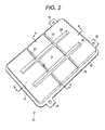
FIG. 2 is a perspective view of the impact energy absorber according to the embodiment as viewed from the opposite direction to that inFIG. 1 ; -
FIG. 3 is a cross-sectional view of the impact energy absorber taken along the line A-A ofFIG. 2 ; -
FIG. 4 is a cross-sectional view of the impact energy absorber taken along the line B-B ofFIG. 2 ; -
FIG. 5 is a schematic cross-sectional view illustrating the impact energy absorber according to the embodiment installed inside a door panel; -
FIG. 6 is a schematic cross-sectional view illustrating the impact energy absorber according to the embodiment installed inside a ceiling panel; -
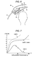
FIG. 7 is a graph illustrating a result of an impact loading test using the impact energy absorber according to the embodiment where displacement percentage is on the horizontal axis, and load is on the vertical axis; -
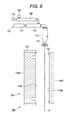
FIG. 8 is a schematic diagram illustrating split mold blocks opened in a forming process to form the impact energy absorber according to the embodiment; -
FIG. 9 is a schematic diagram illustrating a hermetic space formed between a cavity and a thermoplastic resin sheet in the forming process to form the impact energy absorber according to the embodiment; -
FIG. 10 is a schematic diagram illustrating the thermoplastic resin sheet formed by reducing pressure in the forming process to form the impact energy absorber according to the embodiment; -
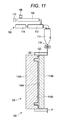
FIG. 11 is a schematic diagram illustrating the split mold blocks clamped in the forming process to form the impact energy absorber according to the embodiment; -
FIG. 12 is a schematic diagram illustrating the impact energy absorber taken out by opening the split mold blocks in the forming process to form the impact energy absorber according to the embodiment; -
FIG. 13 is a schematic lateral sectional view illustrating the cavity of the split mold blocks to form the impact energy absorber according to the embodiment; -
FIGS. 14A, 14B, and 14C are schematic cross-sectional views illustrating the impact energy absorber according to the embodiment before and after the deformation:FIG. 14A is a cross-sectional view of the impact energy absorber before the deformation,FIG. 14B is a cross-sectional view of the impact energy absorber when a impact load is applied to a long groove side, andFIG. 14C is a cross-sectional view of the impact energy absorber when the impact load is applied from the opposite direction to that inFIG. 14B ; and -
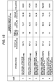
FIG. 15 is a table of test conditions and test results of the impact energy absorber according to the embodiment. - In the following detailed description, for purpose of explanation, numerous specific details are set forth in order to provide a thorough understanding of the disclosed embodiments. It will be apparent, however, that one or more embodiments may be practiced without these specific details. In other instances, well-known structures and devices are schematically shown in order to simplify the drawing.
- It is an object of this disclosure to provide a resin impact energy absorber that ensures a sufficient deformation stroke not only in the case where a uniform impact load is applied to the whole energy absorber but also in the case where an impact load is obliquely applied. The resin impact energy absorber also reduces local variation in energy-absorbing property.
It is another object of this disclosure to provide a method for forming a low-cost and lightweight resin energy absorber with a simple structure. The lightweight resin energy absorber has a good energy-absorbing property with a good formability. - A resin impact energy absorber for vehicle according to one aspect of this disclosure has a single wall solid plate structure. The resin impact energy absorber includes a peripheral wall, a planar portion surrounded by the peripheral wall, and a plurality of first protrusions. The first protrusions are parallel to one another at a predetermined interval in the planar portion. The first protrusion includes a pair of inclined vertical walls and a top wall. The pair of inclined vertical walls projects from the planar portion. The inclined vertical walls face one another. The top wall couples tops of the pair of inclined vertical walls with one another at approximately the same height as the peripheral wall. The pair of inclined vertical walls is inclined at a predetermined inclination angle such that the pair of inclined vertical walls comes close to one another as approaching from the planar portion to the top wall. The planar portion includes one plate surface and another plate surface. At least one of the one plate surface and the other plate surface includes an impact load receiving surface.
- With the resin impact energy absorber for vehicle thus configured, the first protrusions independently deform when the impact load is applied to the one plate surface or the other plate surface of the planar portion. This reduces increase in repulsion force in response to the impact load. The first protrusion may be formed by forming the first long deep groove from the one plate surface to the other plate surface. The first protrusion includes the pair of inclined vertical walls facing one another, and the top wall that couples tops of the pair of inclined vertical walls with one another at approximately the same height as the peripheral wall.
In the resin impact energy absorber for vehicle, the pair of inclined vertical walls is inclined at a predetermined inclination angle such that the pair of inclined vertical walls comes close to one another as approaching from the planar portion to the top wall. This inclination causes the top walls and the respective inclined vertical walls of the plurality of first protrusions to receive the impact load in the case where the impact load is applied in a direction approximately perpendicular to the planar portion. This reduces bottoming of the top wall against the planar portion. This ensures a sufficient absorption stroke of the impact energy. The resin impact energy absorber for vehicle may include the second protrusion. The second protrusion couples the inclined vertical walls of the adjacent first protrusion with one another, and also couples the peripheral wall with the inclined vertical walls of the adjacent first protrusion. This prevents the inclined vertical wall from falling down and ensures a sufficient absorption stroke of the impact energy even in the case where the impact load is obliquely applied. The resin impact energy absorber for vehicle ensures a sufficient absorption stroke not only in the case where a uniform impact load is applied to the whole energy absorber but also in the case where the impact is obliquely applied. Additionally, the resin impact energy absorber for vehicle reduces local variation in energy-absorbing property. - The first protrusion may have a cross-sectional surface with a trapezoidal shape perpendicular to an extending direction of the first protrusion. The top wall may have a rectangular shape.
The first protrusions may be arranged such that the predetermined interval between the adjacent first protrusions is equal to or larger than a protrusion height of the first protrusions.
Further, the first protrusion may have the top wall with a width of 8 to 25 mm and the protrusion height of 10 to 90 mm.
The planar portion has a rectangular shape with one pair of opposing sides and the other pair of opposing sides. The first protrusion extends parallel to the one pair of opposing sides. The second protrusion may extend in a straight line parallel to the other pair of opposing sides so as to couple the one pair of opposing sides with one another.
Further, the first protrusions may extend over the whole one pair of opposing sides of the rectangle planar portion. - The plurality of first protrusions may be formed by forming a plurality of long grooves along a mold cavity. The plurality of long grooves is formed by at least one of vacuuming and pressing. The vacuuming includes vacuuming the molten thermoplastic resin sheet from the mold cavity side. The pressing includes pressing the molten thermoplastic resin sheet from the opposite side of the mold cavity.
- The predetermined inclination angle may be 3 to 10 degrees.
Additionally, the peripheral wall may include a projecting flange at the outer peripheral edge of the peripheral wall. The projecting flange projects outward from the planar portion. The projecting flange may include an installation portion to be coupled with a vehicle. - A method for forming a resin impact energy absorber for vehicle according to one aspect of this disclosure includes: locating a molten thermoplastic resin sheet to face a mold cavity such that the molten thermoplastic resin sheet has an outer border outside the mold cavity, wherein the mold cavity has a long groove to form a protrusion of the resin impact energy absorber for vehicle on a surface of the mold cavity; forming a hermetic space between the mold cavity and a surface of the thermoplastic resin sheet that faces the mold cavity; and forming by vacuuming the thermoplastic resin sheet through the hermetic space so as to press the thermoplastic resin sheet against the mold cavity. The method forms a protrusion having a complementary shape to the long groove by projecting the thermoplastic resin sheet from a surface facing the mold cavity to a surface at the mold cavity side.
- The method for forming a resin impact energy absorber for vehicle forms the following resin impact energy absorber for vehicle different from a conventional configuration that absorbs impact energy through grid-shaped ribs formed by the injection forming method. The resin impact energy absorber for vehicle receives the impact load with simplified protrusions in a long groove shape disposed in the planar portion. This prevents the protrusions from falling down while keeping thin protrusions themselves even in the case where the impact load is obliquely applied. This results in ensuring a deformation stroke. On the other hand, in the case where the impact load is locally applied, decreasing the grid width of the grid-shaped ribs causes bottoming of the ribs. In contrast to this, this resin impact energy absorber for vehicle reduces a possibility of such bottoming out and ensures a deformation stroke. The method for forming a resin energy absorber has a low-cost, lightweight, and simplified structure and forms a resin energy absorber having a good energy-absorbing property with a good formability.
- The cavity may include a planar portion including: a plurality of first slender protrusions disposed at first predetermined intervals; and a plurality of second slender protrusions that extends perpendicularly intersecting with the plurality of first slender protrusion. The plurality of second slender protrusions is disposed at second predetermined intervals. The plurality of first slender protrusions may have a protrusion height from the planar portion lower than a protrusion height of the plurality of second slender protrusions from the planar portion.
- A method for forming a resin impact energy absorber for vehicle according to another aspect of this disclosure includes: supplying a molten thermoplastic resin sheet in a vertically downward direction from an extrusion die, wherein the extrusion die is vertically located above a pair of split mold blocks, wherein the pair of split mold blocks includes a mold cavity with a protrusion on a surface of the mold cavity and a pinch-off portion formed in a circular pattern around the mold cavity; locating the thermoplastic resin sheet between the pair of split mold blocks such that the molten thermoplastic resin sheet has an outer border outside the mold cavity; forming a hermetic space between the mold cavity and a surface of the thermoplastic resin sheet that faces the mold cavity; forming by vacuuming the thermoplastic resin sheet through the hermetic space so as to press the thermoplastic resin sheet against the mold cavity; forming a protrusion having a complementary shape to the long groove by projecting the thermoplastic resin sheet from a surface facing the mold cavity to a surface at the mold cavity side; and forming the thermoplastic resin sheet by clamping the pair of split mold blocks by bringing the pinch-off portion in contact.
The method may further include forming the thermoplastic resin sheet in the hermetic space by at least one of pressing and vacuuming. The pressing includes pressing a hermetic space in the pair of split mold blocks. The hermetic space is formed by clamping the pair of split mold blocks. The vacuuming includes vacuuming inside the hermetic space though the clamped pair of split mold blocks. - A resin impact energy absorber for
vehicle 10 according to the embodiment will be specifically described below by referring to the accompanying drawings.
As illustrated inFIGS. 1 and2 , the impact energy absorber forvehicle 10 has a single wall structure that is made of resin and has a rectangular sheet shape. The impact energy absorber forvehicle 10 is integrally formed by a forming method described later. The impact energy absorber forvehicle 10 includes aperipheral wall 12 and a rectangular-shapedplanar portion 14, which is surrounded by theperipheral wall 12. A height of theperipheral wall 12 and a size of the rectangular-shapedplanar portion 14 may be determined in accordance with an installation position of the impact energy absorber forvehicle 10 in a vehicle and an assumed impact load.
Theperipheral wall 12 includes an outer peripheral edge with a projectingflange 16 that projects outward from the rectangularplanar portion 14. The projectingflange 16 includes aninstallation portion 18 that installs the impact energy absorber forvehicle 10 to the vehicle.
As material of the impact energy absorber forvehicle 10, olefin-based resin such as polyethylene and polypropylene, or thermoplastic resin such as amorphous resin is available. More specifically, olefin homopolymer such as ethylene, propylene, butene, isoprene pentene, and methyl pentene, and copolymer such as polyolefin (for example, polypropylene, high density polyethylene) are available. - As illustrated in
FIG. 1 , the rectangularplanar portion 14 has twofirst protrusions 20 arranged in two rows and twosecond protrusions 22 arranged in two rows on its plane.
Thefirst protrusion 20 extends parallel to opposingsides 15, each of which is disposed on one side of the rectangularplanar portion 14, over approximately the wholeone opposing side 15. Thefirst protrusion 20 is separated from the adjacentone opposing side 15 at a predetermined interval.
As illustrated inFIGS. 2 and3 , thefirst protrusion 20 is configured by forming longdeep grooves 24 from oneplate surface 17 to theother plate surface 19 of the rectangularplanar portion 14. Thefirst protrusion 20 includes a pair of inclinedvertical walls 26 facing one another and atop wall 28, which couples tops of the respective inclinedvertical walls 26 at approximately the same height of theperipheral wall 12. - The pair of inclined
vertical walls 26 facing one another is inclined at a predetermined inclination angle α (seeFIG. 14 ) such that the pair of inclinedvertical walls 26 comes close to one another as approaching from the rectangularplanar portion 14 to thetop wall 28. Thefirst protrusion 20 has a cross-sectional surface with a trapezoidal shape perpendicular to the extending direction of thefirst protrusion 20. Thetop wall 28 has a rectangular shape.
A thickness of a single rectangular thin plate is determined, as described later, such that the impact energy absorber forvehicle 10 has a desired energy-absorbing property and ensures lightweight. The thickness of a single rectangular thin plate is determined in accordance with a protrusion height H of thefirst protrusion 20, a width W of thetop wall 28 of thefirst protrusion 20, an inclination angle α of the inclined vertical wall, and a distance D between the adjacent first protrusions 20 (seeFIG. 14 ).
In particular, the predetermined inclination angle α may be determined in the following respects, as described later. This requires preventing the inclinedvertical walls 26 from falling down in the case where an impact load is obliquely applied to the rectangularplanar portion 14. This also requires preventing thetop wall 28 from depressing (bottoming) against the rectangularplanar portion 14 in the case where an impact is perpendicularly (squarely) applied to the rectangularplanar portion 14. The predetermined inclination angle α is preferred to be 3 to 10 degrees. If the predetermined inclination angle α is smaller than 3 degrees, it is effective to prevent thetop wall 28 from bottoming while the inclinedvertical walls 26 tend to fall down. On the other hand, if the predetermined inclination angle α is larger than 10 degrees, it is effective to prevent the inclinedvertical walls 26 from falling down while thetop wall 28 tends to bottom out. - The
top wall 28 includes a top surface that has the same height as the top surface of the projectingflange 16. This allows not only thefirst protrusions 20 but also theperipheral wall 12 to receive an impact load when the impact load is applied to the impact energy absorber forvehicle 10. This ensures sufficient deformation stroke of the impact energy absorber forvehicle 10, thus absorbing the impact energy by elastic deformation or plastic deformation.
In this respect, in order to obtain a desired energy-absorbing property, thetop wall 28 may have a width W of 8 to 25 mm, thefirst protrusions 20 may have a protrusion height H of 10 to 90 mm, and a distance D between thefirst protrusions 20 may be equal to or more than the protrusion height H of thefirst protrusions 20. - In contrast, as illustrated in
FIG. 1 , thesecond protrusion 22 extends in a straight line similarly to thefirst protrusion 20. Thesecond protrusion 22 extends parallel to other opposingsides 21, which are disposed on the other sides of the rectangularplanar portion 14, over the whole other opposingsides 21. Thesecond protrusion 22 is separated from the adjacent other opposingside 21 at a predetermined interval. Thesecond protrusion 22 intersects with thefirst protrusions 20. More specifically, thesecond protrusions 22 couple theperipheral wall 12 with the adjacent inclinedvertical wall 26 of thefirst protrusions 20 and couple the adjacent two inclinedvertical walls 26 of the twofirst protrusions 20 with one another. As illustrated inFIG. 2 , thesecond protrusion 22 is configured by forming a longshallow groove 23 extending from the oneplate surface 17 to theother plate surface 19 of the rectangularplanar portion 14 similarly to thefirst protrusions 20. As illustrated inFIG. 4 , thesecond protrusions 22 include a pair of inclinedvertical walls 25 facing one another and atop wall 27, which couples tops of the inclinedvertical walls 25 with one another. The pair of inclinedvertical walls 25 facing one another is inclined at a predetermined inclination angle such that the pair of inclinedvertical walls 25 comes close to one another as approaching from the rectangularplanar portion 14 to thetop wall 27. Thesecond protrusion 22 has a cross-sectional surface with a trapezoidal shape perpendicular to the extending direction of thesecond protrusions 22. Thetop wall 27 has a rectangular shape. - The
top wall 27 has a top surface that has a lower height than that of the top surface of the projectingflange 16. Thetop wall 27 is coupled at a root portion of thefirst protrusion 20. This prevents the inclinedvertical wall 26 of thefirst protrusion 20 from falling down especially in the case where an impact load is obliquely applied to the rectangularplanar portion 14. This ensures a sufficient deformation stroke of the inclinedvertical wall 26. - As illustrated in
FIG. 5 , the impact energy absorber forvehicle 10 is installed at adoor panel 30. More specifically, the impact energy absorber forvehicle 10 is secured to adoor trim 34 in a hollow portion between aninner panel 32 and thedoor trim 34. The impact energy absorber forvehicle 10 is secured to the door trim 34 with a clip (not shown) via theinstallation portion 18 of the projectingflange 16. This allows a shoulder portion or a waist portion of a vehicle occupant to be brought into contact with a plate surface side (backside surface side) of the impact energy absorber forvehicle 10 via the door trim 34 when vehicle side collision occurs. This crushes the impact energy absorber forvehicle 10, thus reducing stress applied to the vehicle occupant.
FIG. 6 illustrates a modification of the impact energy absorber forvehicle 10. As illustrated inFIG. 6 , an impact energy absorber forvehicle 10a according to the modification is installed at aceiling panel 38. The impact energy absorber forvehicle 10a is secured to aroof trim 42 in a hollow portion between aninner panel 40 and theroof trim 42. The impact energy absorber forvehicle 10a is secured to aninner surface 44 of the roof trim 42 at atop surface 46 of thetop wall 28 of the impact energy absorber forvehicle 10a by bonding with hot melt adhesive. This allows the head of a vehicle occupant to be brought into contact with a plate surface side (front surface side) of the impact energy absorber forvehicle 10a via the roof trim 42 when vehicle side collision occurs, thus protecting the head of the vehicle occupant. - Next, by referring to
FIGS. 8 to 12 , the method for forming the impact energy absorber forvehicle 10 will be described.
As illustrated inFIG. 8 , a formingapparatus 100 for the impact energy absorber forvehicle 10 includes an extrudingmachine 102 for molten resin and a clampingmachine 104 ofmolds machine 102. The formingapparatus 100 introduces molten thermoplastic resin, which is extruded from the extrudingmachine 102, to the clampingmachine 104, thus forming the molten thermoplastic resin at the clampingmachine 104. - The extruding
machine 102 includes acylinder 108 with ahopper 106, a screw (not shown) inside thecylinder 108, ahydraulic motor 110 coupled to the screw, anaccumulator 112, which is coupled to thecylinder 108 inside, and aplunger 114 inside theaccumulator 112. Resin pellets charged from thehopper 106 are melted and mixed inside thecylinder 108 by rotation of the screw by thehydraulic motor 110. The molten resin is introduced to an accumulator chamber and then accumulated in a certain amount. The molten resin is introduced to a T-die 113 by drive of theplunger 114. The molten resin is extruded through an extrusion slit (not shown) as a continuous thermoplastic resin sheet P. The thermoplastic resin sheet P is introduced downward while being pressed with a pair ofrollers 115 disposed at a predetermined distance. The thermoplastic resin sheet P is suspended between thesplit mold blocks split mold blocks - The extrusion slit (not shown) is disposed below the T-die 113 facing a vertically downward direction. The thermoplastic resin sheet P, which is extruded from the extrusion slit, is introduced to the vertically downward direction while being suspended from the extrusion slit. The extrusion slit may have a changeable slit width. This allows setting a thickness of the thermoplastic resin sheet P to a desired one. In view of this, the extrusion slit locates the thermoplastic resin sheet P with a desired thickness between the
split mold blocks - On the other hand, the clamping
machine 104 includes two splitmold blocks split mold blocks
The two splitmold blocks cavities cavities cavities
Thecavities vehicle 10, which is formed from the molten thermoplastic resin sheet P. - The
mold 116B includes a pinch-off portion 122 around thecavity 118B. The pinch-off portion 122 is formed around thecavity 118B in a circular pattern and projected toward themold 116A, which faces themold 116B. This brings a distal end portion of the pinch-off portion 122 at themold 116B into contact with themold 116A when the two splitmold blocks - The mold driving device drives each of the two split
mold blocks mold blocks mold blocks mold blocks off portion 122 of thesplit mold block 116B is brought into contact with themold 116A so as to form a hermetic space between the two splitmold blocks - A
frame 120 slidably fits an outer periphery portion of thesplit mold block 116A from the outer side of thesplit mold block 116A. A frame moving device (not shown) moves theframe 120 relative to thesplit mold block 116A. More specifically, theframe 120 projects from themold 116A toward themold 116B. This brings theframe 120 into contact with one side face of the thermoplastic resin sheet P, which is located between themolds
Thesplit mold block 116A includes a vacuum suction chamber (not shown) inside. The vacuum suction chamber communicates with thecavity 118A through a suction hole (not shown). Suction of the vacuum suction chamber through the suction hole sucks the thermoplastic resin sheet P to thecavity 118A, thus forming a shape along the outer surface of thecavity 118A.
FIG. 13 is a schematic lateral sectional view illustrating thecavity 118A of the two splitmold blocks FIG. 13 , thecavity 118A includes, on its outer surface, a plurality of firstslender protrusions slender protrusions 132. The firstslender protrusions slender protrusions 132 extend perpendicularly intersecting with the plurality of firstslender protrusions slender protrusions cavity 118A, which height is higher than heights of the plurality of secondslender protrusions 132 from the outer surface of thecavity 118A.
Thesplit mold blocks molds molds - A method for forming the impact energy absorber for
vehicle 10 using the formingapparatus 100 for the impact energy absorber forvehicle 10 thus configured will be described.
First, as illustrated inFIG. 8 , the extrusion slit (not shown) of the T-die 113 intermittently extrudes the accumulated thermoplastic resin at a predetermined rate of extrusion amount per unit time. The molten thermoplastic resin swells, and is extruded with a predetermined thickness at a predetermined extrusion rate. The thermoplastic resin is suspended downward as the molten thermoplastic resin sheet P. The thermoplastic resin sheet P is then located between thesplit mold blocks rollers 115 before forming and after extruding. This flattens out the cylindrical parison into a sheet shape.
In this case, it is possible to set the thickness of the thermoplastic resin sheet P at a desired thickness. This thickness can be independently set by adjusting a slit width of the extrusion slit opening or by adjusting a distance between the pair ofrollers 115. - Next, as illustrated in
FIG. 9 , the frame moving device (not shown) moves theframe 120 of thesplit mold block 116A from thesplit mold block 116A toward the thermoplastic resin sheet P, thus bringing theframe 120 into contact with a side face of the thermoplastic resin sheet P. This forms ahermetic space 140 with the side face of the thermoplastic resin sheet P, an inner circumferential surface of theframe 120, and thecavity 118A. - Next, as illustrated in
FIG. 10 , air in thehermetic space 140 is sucked through the suction hole by the vacuum suction chamber. Accordingly, the thermoplastic resin sheet P is sucked to thecavity 118A and formed in a shape along the surface of thecavity 118A. More specifically, thefirst protrusions second protrusion 132 of thecavity 118A (seeFIG. 13 ) form long grooves from a surface of the thermoplastic resin sheet P facing thecavity 118A toward a surface of thecavity 118A side. The long grooves have a shape complementary to thefirst protrusions second protrusion 132. This forms thefirst protrusions 20, thesecond protrusions 22, and the peripheral wall 12 (seeFIG. 1 ) on the surface of thecavity 118A.
Next, as illustrated inFIG. 11 , thesplit mold blocks off portion 122 of thesplit mold block 116B defines a frame of a peripheral edge portion of the thermoplastic resin sheet P. - Next, as illustrated in
FIG. 12 , thesplit mold blocks impact energy absorber 10 is completed.
As described above, these processes are repeated each time the molten thermoplastic resin is extruded intermittently. This ensures an effective production of theimpact energy absorber 10 one after another. That is, the extrusion forming ensures extruding the molten thermoplastic resin sheet intermittently, and forming the extruded thermoplastic resin sheet in a predetermined shape using themolds
The above-described method for forming a resin impact energy absorber for vehicle allows forming the following resin impact energy absorber for vehicle different from a conventional configuration that absorbs impact energy with grid-shaped ribs formed by the injection forming method. This resin impact energy absorber for vehicle receives an impact load using long-groove-shaped simple protrusions on the planar portion. This prevents the protrusions from falling down while keeping thin protrusions even in the case where the impact load is obliquely applied. This results in ensuring a deformation stroke. On the other hand, in the case where an impact load is locally applied, decreasing the grid width of the grid-shaped ribs causes a bottoming of the ribs. In contrast to this, this resin impact energy absorber for vehicle reduces a possibility of such bottoming and ensures a deformation stroke. The forming method forms a resin energy absorber that has: a low-cost, lightweight, and simplified structure; and a good energy-absorbing property, with a good formability.
A double-wall structure, which is formed by blow forming, has a thin thickness of vertical walls (impact absorbing ribs) as a whole. This makes it difficult to ensure an impact absorbing amount by crushing while reducing weight of the impact absorber. In contrast, the resin impact energy absorber according to the embodiment has a single wall structure that ensures a thickness of a vertical wall. This ensures an impact absorbing stroke when compressing the whole surface even in the case where the whole resin amount is reduced. - A forming procedure is not limited to the above-described procedure for forming resin material by forming the hermetic space between the
cavity 118A and the resin material before clamping thesplit mold blocks cavity 118A side. For example, resin material may be formed by clamping thesplit mold blocks split mold blocks split mold blocks cavity 118A side. This method applies blow pressure while removing air accumulated in a recess of thecavity 118A by sucking, thus ensuring good formability. - The inventor has tested the impact energy absorber according to the embodiment to evaluate its impact energy-absorbing property in the following manner.
-
- (i) The test was carried out using an impact-testing machine made by Hodogaya Giken Corporation. The impact-testing machine includes, on its distal portion, a load acting surface with a diameter of 60 mm. In the test, an impact probe with a weight of 20 kg collided with the impact energy absorber at a speed of 20 km per hour, for calculating impact energy at a compressive strain of 70%.
- (ii) Testing parameter
The testing parameter includes, firstly, types of structure of the impact energy absorber, secondly, types of rib that receives impact load, thirdly, a top wall width of a slit-shaped rib (long deep groove formed with the first protrusion), and fourthly, existence of the long shallow groove (long shallow groove formed with the second protrusion) in the slit-shaped rib (long deep groove formed with the first protrusions). The types of the structure of the impact energy absorber include the single wall structure and the hollow wall structure with opposed walls. The types of rib that receives impact load include the truncated-cone-shaped rib and the slit-shaped rib (long deep groove formed with the first protrusion). In view of this,Case 1 toCase 5 are set as illustrated inFIG. 15 .
Case 5 corresponds to the impact energy absorber according to the embodiment. - (iii) As illustrated in
FIG. 15 ,Case 1 toCase 5 were each tested for: a wholly uniform impact load; a local impact load; and an oblique impact load as loading methods of the impact load with the impact probe. The oblique impact load is applied from an inclined direction at 30 degrees with respect to almost the whole inner side of the peripheral wall. -
- 1. Specifications of the impact energy absorber in
Cases 3 to 5 are follows. Specifications other than the top wall width and the second protrusion are common inCases 3 to 5.- (A) Material: polypropylene
- (B) Thickness: 1.9 mm
- (C) Size: 310 mm Height × 210 mm Width
-
Number: 2 Protrusion height: 40 mm Distance between adjacent protrusions: 60 mm Width of top wall: 5 mm (Case 3) or 10 mm (Case 4) Length of top wall: 290 mm Inclination angle of the inclined vertical wall: 3 degrees -
Number: 2 (Case 5) Protrusion height: 10 mm Distance between adjacent protrusions: 85 mm Width of top wall: 3 mm Length of top wall: 210 mm as a whole Length of top wall between the peripheral wall and the adjacent inclined vertical wall of the first protrusion: 70 mm Length of top wall between the adjacent inclined vertical walls of the first protrusions: 50 mm Inclination angle of the inclined vertical wall: 3 degrees - An impact load was applied to a front surface side (one plate surface side) that has an opening side of the long groove formed with the first protrusions and the second protrusion of the impact energy absorber.
-
FIGS. 7 and15 show test results.FIG. 15 illustrates absorbed energies when respective impact energy absorbers are crushed to a compressive strain of 70% within a range where the impact load does not exceed 6 kN. - (i) As illustrated in
FIG. 7 ,Case 4 andCase 5, which are different fromCase 3, restrict a rapid increase in the impact load until displacement percentage reaches 70%. On the other hand,Case 4 andCase 5, which are different fromCase 2, also restrict a rapid decrease in the impact load until displacement percentage reaches 70%. - (ii) As illustrated in
FIG. 15 ,Case 2 toCase 5 where weight and thickness are approximately the same do not have a significant difference in the impact energy-absorbing property at compressing the whole surface. There is no significant difference in the impact energy-absorbing property between the hollow wall structure ofCase 1 and each of the single wall structures ofCase 2 toCase 5 when compressing the whole surface. - (iii) Among
Case 2 toCase 5, Case 5 (the slit rib in the long deep groove shape) has the best impact energy-absorbing property for a local impact load, Case 2 (the truncated-cone-shaped rib) has the worst impact energy-absorbing property, andCases 4 and 5 (the slit rib in the long deep groove shape) do not have a significant difference from one another. This is because the slit rib in the long deep groove shape has better integrity of the ribs than the truncated-cone-shaped rib, which leads to smaller local variation in impact energy-absorbing property. Further, the comparison ofCase 3 withCase 4 has demonstrated that the top wall width affects the impact energy-absorbing property for the local impact load. - (iv) The comparison of
Case 4 withCase 5 has demonstrated that the impact energy-absorbing property for the impact load from an oblique direction is better inCase 5. The inventor assumed as follows. The second protrusion in the long shallow groove shape couples the inclined vertical walls of the adjacent first protrusions with one another. This prevents the inclined vertical wall falling down when the impact load is obliquely applied. This ensures a deformation stroke that absorbs impact energy. - (v) The comparison of
Case 1 withCase 5 has demonstrated that there is no significant local variation in impact energy-absorbing property among respective cases of applying a wholly uniform impact load, a local impact load, and an oblique impact load. This shows that the single wall structure has an advantage in ensuring a lightweight impact energy absorber compared with the hollow wall structure. - As illustrated in
FIG. 14 (in the case of local load), in the resin impact energy absorber forvehicle 10 configured as described above, thefirst protrusions 20 independently deform when the impact load is applied to one plate surface or the other plate surface of theplanar portion 14. This reduces an increase in a repulsion force in response to the impact load. Thefirst protrusion 20 forms the longdeep groove 24 from the one plate surface to the other plate surface. The longdeep groove 24 includes the pair of inclinedvertical walls 26 facing one another, and atop wall 28 that couples tops of the respective inclinedvertical walls 26 at approximately the same height as theperipheral wall 12. The inclinedvertical walls 26 are inclined at a predetermined inclination angle α such that the inclinedvertical walls 26 come close one another as approaching from theplanar portion 14 to thetop wall 28. The inclination reduces the impact load received by thetop wall 28 and the respective inclinedvertical walls 26 of the plurality offirst protrusions 20 in the case where the impact load is applied in a direction approximately perpendicular to theplanar portion 14. This reduces bottoming of thetop wall 28 against theplanar portion 14 and ensures a sufficient absorption stroke of the impact energy. Thesecond protrusion 22 couples the inclinedvertical walls 26 of the adjacentfirst protrusions 20 with one another and couples theperipheral wall 12 with the inclinedvertical wall 26. This prevents the inclinedvertical wall 26 from falling down even in the case where the impact load is obliquely applied. This ensures the sufficient absorption stroke of the impact energy. The resin impact energy absorber forvehicle 10 ensures a sufficient deformation stroke not only in the case where a uniform impact load is applied to the whole energy absorber but also in the case where the impact is obliquely applied. Further, this reduces local variation in energy-absorbing property. - It will be appreciated that the present disclosure will not be limited to the embodiment described above, but various modifications and changes are possible by one of ordinary skill in the art without departing from the technical scope of the present disclosure.
For example, while in the embodiment, thesecond protrusion 22, which couples the inclinedvertical walls 26 of the adjacentfirst protrusions 20 with one another, is described as a member disposed in a straight line perpendicular to the extending direction of thefirst protrusion 20 and intersecting with all thefirst protrusions 20 for convenience in forming. This, however, should not be construed in a limiting sense. Specifically, thesecond protrusion 22 of the present disclosure is not necessarily disposed in a straight line to intersect with all thefirst protrusions 20 insofar as thesecond protrusion 22 is coupled at a root portion of the inclinedvertical walls 26 and prevents the inclinedvertical walls 26 from falling down in the case where the impact load is obliquely applied. For example, onesecond protrusion 22 that couples the inclinedvertical walls 26 of the adjacentfirst protrusions 20 in a line with one another, and the othersecond protrusion 22 that couples the inclinedvertical walls 26 of the adjacentfirst protrusions 20 in the next line with one another may be disposed while shifted in the extending direction of thefirst protrusion 20.
In the embodiment, the thermoplastic resin sheet is extruded downward in a molten state and located between the pair ofsplit mold blocks split mold blocks - The resin impact energy absorber for vehicle according to the present disclosure may be configured as follows. For example, the resin impact energy absorber having a single wall solid plate structure includes a peripheral wall, a planar portion surrounded by the peripheral wall, a plurality of first protrusions, and a second protrusion. The first protrusion is formed by forming a plurality of first long grooves parallel to one another at the predetermined interval in the planar portion. The second protrusion extends in a direction intersecting with the plurality of first protrusions in the planar portion. The second protrusion is formed by forming a second long groove in the planar portion. The first protrusion includes a pair of inclined vertical walls and a top wall. The pair of inclined vertical walls projects from the planar portion. The inclined vertical walls face one another. The top wall couples tops of the pair of inclined vertical walls with one another at approximately the same height as the peripheral wall. The pair of inclined vertical walls is inclined at a predetermined inclination angle such that the pair of inclined vertical walls comes close to one another as approaching from the planar portion to the top wall. The second protrusion couples the peripheral wall with the inclined vertical wall of the first protrusion closest to the peripheral wall, and couples the inclined vertical walls of the adjacent first protrusions with one another. The second protrusion has a protrusion height lower than a protrusion height of the plurality of first protrusions. The second protrusion is coupled with the first protrusions at root portions. The planar portion includes one plate surface and another plate surface. At least one of the one plate surface and the other plate surface includes an impact load receiving surface.
- The resin impact energy absorber having a single wall solid plate structure may include a peripheral wall, a planar portion surrounded by the peripheral wall, and a plurality of first protrusions. The first protrusions are parallel to one another at a predetermined interval in the planar portion. The plurality of first protrusions is formed by forming a plurality of long grooves along a mold cavity from one surface to the other surface. The plurality of long grooves is formed by at least one of vacuuming and pressing. The vacuuming includes vacuuming the molten thermoplastic resin sheet from the one surface. The pressing includes pressing the molten thermoplastic resin sheet from the other surface. The first protrusion includes a pair of inclined vertical walls and a top wall. The pair of inclined vertical walls projects from the planar portion. The inclined vertical walls face one another. The top wall couples tops of the pair of inclined vertical walls with one another at approximately the same height as the peripheral wall. The pair of inclined vertical walls is inclined at a predetermined inclination angle such that the pair of inclined vertical walls comes close to one another as approaching from the planar portion to the top wall. The first protrusion has the top wall with a width of 8 to 25 mm. The planar portion includes one plate surface and another plate surface. At least one of the one plate surface and the other plate surface includes an impact load receiving surface.
The foregoing detailed description has been presented for the purposes of illustration and description. Many modifications and variations are possible in light of the above teaching. It is not intended to be exhaustive or to limit the subject matter described herein to the precise form disclosed. Although the subject matter has been described in language specific to structural features and/or methodological acts, it is to be understood that the subject matter defined in the appended claims is not necessarily limited to the specific features or acts described above. Rather, the specific features and acts described above are disclosed as example forms of implementing the claims appended hereto.
Claims (17)
- A resin impact energy absorber for vehicle having a single wall solid plate structure, the resin impact energy absorber comprising:a peripheral wall;a planar portion surrounded by the peripheral wall; anda plurality of first protrusions, the first protrusions being parallel to one another at a predetermined interval in the planar portion, whereinthe first protrusion includes:a pair of inclined vertical walls that projects from the planar portion, the inclined vertical walls facing one another; anda top wall that couples tops of the pair of inclined vertical walls with one another at approximately the same height as the peripheral wall,the pair of inclined vertical walls is inclined at a predetermined inclination angle such that the pair of inclined vertical walls comes close to one another as approaching from the planar portion to the top wall, andthe planar portion includes one plate surface and another plate surface, at least one of the one plate surface and the other plate surface including an impact load receiving surface.
- The resin impact energy absorber for vehicle according to claim 1, further comprising:a second protrusion that extends in a direction intersecting with the plurality of first protrusions in the planar portion, whereinthe second protrusion couples the peripheral wall with the inclined vertical wall of the first protrusion closest to the peripheral wall, and couples the inclined vertical walls of the adjacent first protrusions with one another,the second protrusion has a protrusion height lower than a protrusion height of the plurality of first protrusions, andthe second protrusion is coupled with the first protrusions at root portions.
- The resin impact energy absorber for vehicle according to claim 2, wherein
the plurality of first protrusions is formed by forming a plurality of first long grooves parallel to one another at the predetermined interval in the planar portion, and
the second protrusion is formed by forming a second long groove that extends in the direction intersecting with the plurality of first protrusions in the planar portion. - The resin impact energy absorber for vehicle according to claim 1, wherein
the first protrusion has a cross-sectional surface with a trapezoidal shape perpendicular to an extending direction of the first protrusion, and
the top wall has a rectangular shape. - The resin impact energy absorber for vehicle according to claim 1, wherein
the first protrusions are arranged such that the predetermined interval between the adjacent first protrusions is equal to or larger than a protrusion height of the first protrusions. - The resin impact energy absorber for vehicle according to claim 1, wherein
the first protrusion has the top wall with a width of 8 to 25 mm, and
the first protrusion has a protrusion height of 10 to 90 mm. - The resin impact energy absorber for vehicle according to claim 1, wherein
the planar portion has a rectangular shape with one pair of opposing sides and another pair of opposing sides,
the first protrusion extends parallel to the one pair of opposing sides, and
the second protrusion extends in a straight line parallel to the other pair of opposing sides so as to couple the one pair of opposing sides with one another. - The resin impact energy absorber for vehicle according to claim 7, wherein
the first protrusions extend over the whole one opposing sides of the planar portion. - The resin impact energy absorber for vehicle according to claim 1, wherein
the plurality of first protrusions is formed by forming a plurality of first long grooves along a mold cavity, the plurality of first long grooves being formed by at least one of vacuuming and pressing, the vacuuming including vacuuming the molten thermoplastic resin sheet from the mold cavity side, the pressing including pressing the molten thermoplastic resin sheet from an opposite side of the mold cavity. - The resin impact energy absorber for vehicle according to claim 9, wherein
the first protrusion has the top wall with a width of 8 to 25 mm. - The resin impact energy absorber for vehicle according to claim 10, wherein
the first protrusion has the protrusion height of 10 to 90 mm. - The resin impact energy absorber for vehicle according to claim 1, wherein
the predetermined inclination angle is 3 to 10 degrees. - The resin impact energy absorber for vehicle according to claim 1, wherein
the peripheral wall includes a projecting flange at an outer peripheral edge of the peripheral wall, the projecting flange projecting outward from the planar portion, and
the projecting flange includes an installation portion to be coupled with a vehicle. - A method for forming a resin impact energy absorber for vehicle, the method comprising:locating a molten thermoplastic resin sheet to face a mold cavity such that the molten thermoplastic resin sheet has an outer border outside the mold cavity, the mold cavity having a long groove to form a protrusion of the resin impact energy absorber for vehicle on a surface of the mold cavity;forming a hermetic space between the mold cavity and a surface of the thermoplastic resin sheet that faces the mold cavity; andforming by vacuuming the thermoplastic resin sheet through the hermetic space so as to press the thermoplastic resin sheet against the mold cavity, whereinthe method forms a protrusion having a complementary shape to the long groove by projecting the thermoplastic resin sheet from a surface facing the mold cavity to a surface at the mold cavity side.
- The method for forming a resin impact energy absorber for vehicle according to claim 14, wherein
the mold cavity includes a planar portion including:a plurality of first slender protrusions disposed at a first predetermined interval; anda plurality of second slender protrusions that extends perpendicularly intersecting with the plurality of first slender protrusions, the plurality of second slender protrusions being disposed at a second predetermined interval, andthe plurality of first slender protrusions has a protrusion height from the planar portion lower than a protrusion height of the plurality of second slender protrusions from the planar portion. - A method for forming a resin impact energy absorber for vehicle, the method comprising:supplying a molten thermoplastic resin sheet in a vertically downward direction from an extrusion die, the extrusion die being vertically located above a pair of split mold blocks, the pair of split mold blocks including a mold cavity with a protrusion on a surface of the mold cavity and a pinch-off portion formed in a circular pattern around the mold cavity;locating the thermoplastic resin sheet between the pair of split mold blocks such that the molten thermoplastic resin sheet has an outer border outside the mold cavity;forming a hermetic space between the mold cavity and a surface of the thermoplastic resin sheet that faces the mold cavity;forming by vacuuming the thermoplastic resin sheet through the hermetic space so as to press the thermoplastic resin sheet against the mold cavity;forming a protrusion having a complementary shape to the long groove by projecting the thermoplastic resin sheet from a surface facing the mold cavity to a surface at the mold cavity side; andforming the thermoplastic resin sheet by clamping the pair of split mold blocks by bringing the pinch-off portion in contact.
- The method for forming a resin impact energy absorber for vehicle according to claim 16, further comprising:forming the thermoplastic resin sheet in the hermetic space by at least one of pressing and vacuuming, whereinthe pressing includes pressing a hermetic space in the pair of split mold blocks, the hermetic space being formed by clamping the pair of split mold blocks, andthe vacuuming includes vacuuming inside the hermetic space through the clamped pair of split mold blocks.
Applications Claiming Priority (1)
| Application Number | Priority Date | Filing Date | Title |
|---|---|---|---|
| JP2011057101A JP5700210B2 (en) | 2011-03-15 | 2011-03-15 | Impact energy absorber for vehicle and molding method thereof |
Publications (3)
| Publication Number | Publication Date |
|---|---|
| EP2500194A2 true EP2500194A2 (en) | 2012-09-19 |
| EP2500194A3 EP2500194A3 (en) | 2015-06-10 |
| EP2500194B1 EP2500194B1 (en) | 2019-07-03 |
Family
ID=45894223
Family Applications (1)
| Application Number | Title | Priority Date | Filing Date |
|---|---|---|---|
| EP12159689.4A Active EP2500194B1 (en) | 2011-03-15 | 2012-03-15 | Impact energy absorber for vehicle and method for forming the same |
Country Status (3)
| Country | Link |
|---|---|
| US (2) | US9079476B2 (en) |
| EP (1) | EP2500194B1 (en) |
| JP (1) | JP5700210B2 (en) |
Cited By (1)
| Publication number | Priority date | Publication date | Assignee | Title |
|---|---|---|---|---|
| EP3109124A1 (en) * | 2015-06-23 | 2016-12-28 | ALSTOM Transport Technologies | A railway bogie with a winterproof piping and wiring protecting impact guard |
Families Citing this family (9)
| Publication number | Priority date | Publication date | Assignee | Title |
|---|---|---|---|---|
| WO2011149049A1 (en) * | 2010-05-28 | 2011-12-01 | キョーラク株式会社 | Impact absorber and process for producing impact absorber |
| JP5966666B2 (en) * | 2012-06-26 | 2016-08-10 | キョーラク株式会社 | Impact energy absorber |
| US10006515B2 (en) | 2013-09-26 | 2018-06-26 | Kyoraku Co., Ltd. | Impact energy absorber |
| JP6388430B2 (en) * | 2014-04-15 | 2018-09-12 | トヨタ紡織株式会社 | Impact energy absorber |
| JP6292013B2 (en) * | 2014-05-09 | 2018-03-14 | キョーラク株式会社 | Method for forming shock absorber |
| JP6540529B2 (en) * | 2016-02-04 | 2019-07-10 | テイ・エス テック株式会社 | Vehicle interior parts |
| KR102463200B1 (en) * | 2017-12-08 | 2022-11-04 | 현대자동차 주식회사 | Door for vehicle |
| JP7254568B2 (en) * | 2019-03-11 | 2023-04-10 | マブチモーター株式会社 | motor |
| US20230326444A1 (en) * | 2022-04-12 | 2023-10-12 | GM Global Technology Operations LLC | Cast cover with integrated noise mitigation method |
Citations (4)
| Publication number | Priority date | Publication date | Assignee | Title |
|---|---|---|---|---|
| JP2775146B2 (en) | 1994-09-21 | 1998-07-16 | 小島プレス工業株式会社 | Shock absorbing structure for vehicles |
| JP3186563B2 (en) | 1996-01-31 | 2001-07-11 | トヨタ自動車株式会社 | Impact energy absorbing member |
| WO2008105517A1 (en) | 2007-02-28 | 2008-09-04 | Kyoraku Co., Ltd. | Impact absorption body for vehicle |
| JP4597832B2 (en) | 2005-09-30 | 2010-12-15 | 株式会社イノアックコーポレーション | Shock absorbing member for vehicle |
Family Cites Families (37)
| Publication number | Priority date | Publication date | Assignee | Title |
|---|---|---|---|---|
| US3231454A (en) * | 1961-04-14 | 1966-01-25 | Cadillac Products | Cushioning material |
| US3370117A (en) * | 1965-09-16 | 1968-02-20 | Reeves Bros Inc | Crushed polyurethane foam and method of making same |
| GB1136613A (en) | 1965-04-29 | 1968-12-11 | Hiromi Sudo | Improvements in or relating to the molding of articles from thermoplastic resin sheet material |
| US3638992A (en) * | 1969-12-02 | 1972-02-01 | Lloyd T Forshee | Auto and aircraft safety liners |
| US3931383A (en) | 1973-04-13 | 1976-01-06 | General Plastics Corporation | Method for continuously forming plastic sheet with vacuum pressure |
| US3887320A (en) | 1973-04-13 | 1975-06-03 | Gen Plastics Corp | Apparatus for continuously forming plastic sheet and corrugating with vacuum pressure |
| US3971326A (en) * | 1975-05-21 | 1976-07-27 | Extrados Company Limited | Pallet construction |
| US4411121A (en) * | 1981-02-02 | 1983-10-25 | Tate Architectural Products, Inc. | Structural member with truncated conical portion and composite panel including same |
| US4457797A (en) * | 1982-03-08 | 1984-07-03 | E. I. Dupont De Nemours And Company | Process for thermoforming reinforced polymer sheets |
| US4890877A (en) * | 1988-07-12 | 1990-01-02 | General Motors Corporation | Energy absorption system for vehicle door and method of making |
| US5561875A (en) * | 1992-02-20 | 1996-10-08 | Crown Therapeutics, Inc. | Vacuum/heat formed cushion supported on a fluid permeable manifold |
| US5243722A (en) * | 1992-04-06 | 1993-09-14 | Ignaty Gusakov | Fluid cushion |
| US5636866A (en) | 1994-09-21 | 1997-06-10 | Kojima Press Industry Co., Ltd. | Shock absorbing structure for motor vehicle |
| US5851626A (en) * | 1997-04-22 | 1998-12-22 | Lear Corporation | Vehicle acoustic damping and decoupling system |
| FR2774144B1 (en) | 1998-01-23 | 2000-03-31 | Inoplast Sa | ENERGY ABSORPTION UNIT |
| US6342288B1 (en) | 1998-06-24 | 2002-01-29 | Bridgestone Corporation | Shock absorbing material |
| US7404593B2 (en) * | 2000-02-07 | 2008-07-29 | Oakwood Energy Management Inc. | Modular energy absorber of varying topography and method for configuring same |
| JP4360050B2 (en) * | 2001-06-11 | 2009-11-11 | 三菱自動車工業株式会社 | Shock absorber |
| JP4173694B2 (en) * | 2002-06-18 | 2008-10-29 | 株式会社ケーヒン | Bulkhead for vehicle |
| US6878335B2 (en) * | 2002-06-21 | 2005-04-12 | Vital Signs, Inc. | Process of manufacturing a breathing bag and breathing bag manufactured by such process |
| JP3963264B2 (en) * | 2002-09-13 | 2007-08-22 | 河西工業株式会社 | Interior parts for automobiles and manufacturing method thereof |
| WO2004040161A1 (en) * | 2002-10-31 | 2004-05-13 | Kyoraku Co., Ltd. | Impact absorbing body for vehicle |
| DE60333131D1 (en) * | 2003-07-03 | 2010-08-05 | Netshape Energy Man Llc | BUMPER SYSTEM WITH THERMOFORMED ENERGY CONTAINER |
| US20070080562A1 (en) | 2003-11-19 | 2007-04-12 | Hayashi Engineering Inc. | Impact absorbing body |
| US7338038B2 (en) * | 2004-03-12 | 2008-03-04 | Dow Global Technologies, Inc. | Impact absorption structure |
| JP4531468B2 (en) * | 2004-07-14 | 2010-08-25 | 小島プレス工業株式会社 | Shock absorbing structure for vehicle and its mounting structure |
| JP5204480B2 (en) * | 2005-03-31 | 2013-06-05 | キョーラク株式会社 | Interior parts for automobile and method for manufacturing the same |
| US7513566B2 (en) * | 2006-02-06 | 2009-04-07 | Toyota Motor Engineering & Manufacturing North America, Inc. | Headliner stiffener with energy absorbing mechanism |
| US20070196601A1 (en) * | 2006-02-17 | 2007-08-23 | Tredegar Film Products Corporation | Textured film with deep pockets |
| US8029041B2 (en) * | 2008-04-12 | 2011-10-04 | Ford Global Technologies, Llc | Door trim-integrated pelvic impact energy-absorbing construction for vehicle |
| US8152218B2 (en) * | 2008-05-13 | 2012-04-10 | Ford Global Technologies, Llc | Integral pelvic impact energy-absorbing pre-crush protective construction for vehicle door |
| JP2010115941A (en) * | 2008-11-11 | 2010-05-27 | Kasai Kogyo Co Ltd | Energy absorbing body and interior part for vehicle |
| JP2010264971A (en) * | 2009-04-14 | 2010-11-25 | Toyota Boshoku Corp | Mounting structure of resin impact absorber for side impact |
| JP5564237B2 (en) * | 2009-11-27 | 2014-07-30 | 株式会社アステア | Bumper reinforcement |
| WO2011149049A1 (en) * | 2010-05-28 | 2011-12-01 | キョーラク株式会社 | Impact absorber and process for producing impact absorber |
| CN103596744B (en) * | 2011-06-29 | 2015-10-14 | 京洛株式会社 | The manufacture method of the raised flooring material integrated with airduct |
| US9023265B1 (en) * | 2013-01-28 | 2015-05-05 | The Boeing Company | Systems, tools, and methods for forming corrugated structures and apparatuses including corrugated structures |
-
2011
- 2011-03-15 JP JP2011057101A patent/JP5700210B2/en active Active
-
2012
- 2012-03-14 US US13/419,538 patent/US9079476B2/en not_active Expired - Fee Related
- 2012-03-15 EP EP12159689.4A patent/EP2500194B1/en active Active
-
2015
- 2015-06-03 US US14/730,132 patent/US9463761B2/en active Active
Patent Citations (4)
| Publication number | Priority date | Publication date | Assignee | Title |
|---|---|---|---|---|
| JP2775146B2 (en) | 1994-09-21 | 1998-07-16 | 小島プレス工業株式会社 | Shock absorbing structure for vehicles |
| JP3186563B2 (en) | 1996-01-31 | 2001-07-11 | トヨタ自動車株式会社 | Impact energy absorbing member |
| JP4597832B2 (en) | 2005-09-30 | 2010-12-15 | 株式会社イノアックコーポレーション | Shock absorbing member for vehicle |
| WO2008105517A1 (en) | 2007-02-28 | 2008-09-04 | Kyoraku Co., Ltd. | Impact absorption body for vehicle |
Cited By (2)
| Publication number | Priority date | Publication date | Assignee | Title |
|---|---|---|---|---|
| EP3109124A1 (en) * | 2015-06-23 | 2016-12-28 | ALSTOM Transport Technologies | A railway bogie with a winterproof piping and wiring protecting impact guard |
| US10478744B2 (en) | 2015-06-23 | 2019-11-19 | Alstom Transport Technologies | Railway bogie with a winterproof piping and wiring protecting impact guard |
Also Published As
| Publication number | Publication date |
|---|---|
| US20120235443A1 (en) | 2012-09-20 |
| JP5700210B2 (en) | 2015-04-15 |
| EP2500194B1 (en) | 2019-07-03 |
| JP2012192794A (en) | 2012-10-11 |
| US9463761B2 (en) | 2016-10-11 |
| US9079476B2 (en) | 2015-07-14 |
| EP2500194A3 (en) | 2015-06-10 |
| CN102673508A (en) | 2012-09-19 |
| US20150266441A1 (en) | 2015-09-24 |
Similar Documents
| Publication | Publication Date | Title |
|---|---|---|
| US9463761B2 (en) | Impact energy absorber for vehicle and method for forming the same | |
| JP5966666B2 (en) | Impact energy absorber | |
| JP6311717B2 (en) | Impact energy absorber | |
| EP3520995B1 (en) | Mold for manufacturing a resin-laminated board | |
| US20170151747A1 (en) | Resin sandwich panel, and method for manufacturing resin sandwich panel | |
| JP6268427B2 (en) | Resin panel and molding method | |
| JP6292013B2 (en) | Method for forming shock absorber | |
| JP5834797B2 (en) | Manufacturing method of hollow thin panel structure made of bendable or bendable resin | |
| KR101565672B1 (en) | Duct | |
| JP5943058B2 (en) | Impact energy absorber for vehicles | |
| JP6388430B2 (en) | Impact energy absorber | |
| JP6387820B2 (en) | Raising material | |
| CN205416183U (en) | Product mould of double rate EPP car bumper anticollision buffer board | |
| JP4539721B2 (en) | In-mold foam molding apparatus and method, and in-mold foam molding product | |
| JP2001150471A (en) | Method and apparatus for intra-mold foaming and foamed molding molded in mold | |
| KR20120103941A (en) | Press mold for molding plastic plates and molding method of plastic plates using the same | |
| US20120168988A1 (en) | Method for manufacture of tray | |
| CN102673508B (en) | Vehicle impact energy absorber and manufacturing process thereof | |
| CN217223227U (en) | Drawing forming die capable of achieving smooth demolding | |
| JP6974692B2 (en) | Molded body and its manufacturing method | |
| JP6916982B2 (en) | Manufacturing method of laminated structure and laminated structure | |
| JP2015205671A (en) | Manufacturing method for impact absorption material, and impact absorption material | |
| JPH11268572A (en) | Trunk carpet | |
| JP2011225165A (en) | Shock absorbing material and method for manufacturing the same |
Legal Events
| Date | Code | Title | Description |
|---|---|---|---|
| PUAI | Public reference made under article 153(3) epc to a published international application that has entered the european phase |
Free format text: ORIGINAL CODE: 0009012 |
|
| AK | Designated contracting states |
Kind code of ref document: A2 Designated state(s): AL AT BE BG CH CY CZ DE DK EE ES FI FR GB GR HR HU IE IS IT LI LT LU LV MC MK MT NL NO PL PT RO RS SE SI SK SM TR |
|
| AX | Request for extension of the european patent |
Extension state: BA ME |
|
| PUAL | Search report despatched |
Free format text: ORIGINAL CODE: 0009013 |
|
| AK | Designated contracting states |
Kind code of ref document: A3 Designated state(s): AL AT BE BG CH CY CZ DE DK EE ES FI FR GB GR HR HU IE IS IT LI LT LU LV MC MK MT NL NO PL PT RO RS SE SI SK SM TR |
|
| AX | Request for extension of the european patent |
Extension state: BA ME |
|
| RIC1 | Information provided on ipc code assigned before grant |
Ipc: B60J 5/04 20060101AFI20150506BHEP |
|
| 17P | Request for examination filed |
Effective date: 20151209 |
|
| RBV | Designated contracting states (corrected) |
Designated state(s): AL AT BE BG CH CY CZ DE DK EE ES FI FR GB GR HR HU IE IS IT LI LT LU LV MC MK MT NL NO PL PT RO RS SE SI SK SM TR |
|
| STAA | Information on the status of an ep patent application or granted ep patent |
Free format text: STATUS: EXAMINATION IS IN PROGRESS |
|
| 17Q | First examination report despatched |
Effective date: 20180612 |
|
| GRAP | Despatch of communication of intention to grant a patent |
Free format text: ORIGINAL CODE: EPIDOSNIGR1 |
|
| STAA | Information on the status of an ep patent application or granted ep patent |
Free format text: STATUS: GRANT OF PATENT IS INTENDED |
|
| INTG | Intention to grant announced |
Effective date: 20190117 |
|
| GRAS | Grant fee paid |
Free format text: ORIGINAL CODE: EPIDOSNIGR3 |
|
| GRAA | (expected) grant |
Free format text: ORIGINAL CODE: 0009210 |
|
| STAA | Information on the status of an ep patent application or granted ep patent |
Free format text: STATUS: THE PATENT HAS BEEN GRANTED |
|
| AK | Designated contracting states |
Kind code of ref document: B1 Designated state(s): AL AT BE BG CH CY CZ DE DK EE ES FI FR GB GR HR HU IE IS IT LI LT LU LV MC MK MT NL NO PL PT RO RS SE SI SK SM TR |
|
| REG | Reference to a national code |
Ref country code: GB Ref legal event code: FG4D |
|
| REG | Reference to a national code |
Ref country code: CH Ref legal event code: EP Ref country code: AT Ref legal event code: REF Ref document number: 1150560 Country of ref document: AT Kind code of ref document: T Effective date: 20190715 |
|
| REG | Reference to a national code |
Ref country code: IE Ref legal event code: FG4D |
|
| REG | Reference to a national code |
Ref country code: DE Ref legal event code: R096 Ref document number: 602012061583 Country of ref document: DE |
|
| REG | Reference to a national code |
Ref country code: NL Ref legal event code: MP Effective date: 20190703 |
|
| REG | Reference to a national code |
Ref country code: LT Ref legal event code: MG4D |
|
| REG | Reference to a national code |
Ref country code: AT Ref legal event code: MK05 Ref document number: 1150560 Country of ref document: AT Kind code of ref document: T Effective date: 20190703 |
|
| PG25 | Lapsed in a contracting state [announced via postgrant information from national office to epo] |
Ref country code: FI Free format text: LAPSE BECAUSE OF FAILURE TO SUBMIT A TRANSLATION OF THE DESCRIPTION OR TO PAY THE FEE WITHIN THE PRESCRIBED TIME-LIMIT Effective date: 20190703 Ref country code: CZ Free format text: LAPSE BECAUSE OF FAILURE TO SUBMIT A TRANSLATION OF THE DESCRIPTION OR TO PAY THE FEE WITHIN THE PRESCRIBED TIME-LIMIT Effective date: 20190703 Ref country code: HR Free format text: LAPSE BECAUSE OF FAILURE TO SUBMIT A TRANSLATION OF THE DESCRIPTION OR TO PAY THE FEE WITHIN THE PRESCRIBED TIME-LIMIT Effective date: 20190703 Ref country code: BG Free format text: LAPSE BECAUSE OF FAILURE TO SUBMIT A TRANSLATION OF THE DESCRIPTION OR TO PAY THE FEE WITHIN THE PRESCRIBED TIME-LIMIT Effective date: 20191003 Ref country code: SE Free format text: LAPSE BECAUSE OF FAILURE TO SUBMIT A TRANSLATION OF THE DESCRIPTION OR TO PAY THE FEE WITHIN THE PRESCRIBED TIME-LIMIT Effective date: 20190703 Ref country code: NO Free format text: LAPSE BECAUSE OF FAILURE TO SUBMIT A TRANSLATION OF THE DESCRIPTION OR TO PAY THE FEE WITHIN THE PRESCRIBED TIME-LIMIT Effective date: 20191003 Ref country code: PT Free format text: LAPSE BECAUSE OF FAILURE TO SUBMIT A TRANSLATION OF THE DESCRIPTION OR TO PAY THE FEE WITHIN THE PRESCRIBED TIME-LIMIT Effective date: 20191104 Ref country code: LT Free format text: LAPSE BECAUSE OF FAILURE TO SUBMIT A TRANSLATION OF THE DESCRIPTION OR TO PAY THE FEE WITHIN THE PRESCRIBED TIME-LIMIT Effective date: 20190703 Ref country code: NL Free format text: LAPSE BECAUSE OF FAILURE TO SUBMIT A TRANSLATION OF THE DESCRIPTION OR TO PAY THE FEE WITHIN THE PRESCRIBED TIME-LIMIT Effective date: 20190703 Ref country code: AT Free format text: LAPSE BECAUSE OF FAILURE TO SUBMIT A TRANSLATION OF THE DESCRIPTION OR TO PAY THE FEE WITHIN THE PRESCRIBED TIME-LIMIT Effective date: 20190703 |
|
| PG25 | Lapsed in a contracting state [announced via postgrant information from national office to epo] |
Ref country code: ES Free format text: LAPSE BECAUSE OF FAILURE TO SUBMIT A TRANSLATION OF THE DESCRIPTION OR TO PAY THE FEE WITHIN THE PRESCRIBED TIME-LIMIT Effective date: 20190703 Ref country code: LV Free format text: LAPSE BECAUSE OF FAILURE TO SUBMIT A TRANSLATION OF THE DESCRIPTION OR TO PAY THE FEE WITHIN THE PRESCRIBED TIME-LIMIT Effective date: 20190703 Ref country code: GR Free format text: LAPSE BECAUSE OF FAILURE TO SUBMIT A TRANSLATION OF THE DESCRIPTION OR TO PAY THE FEE WITHIN THE PRESCRIBED TIME-LIMIT Effective date: 20191004 Ref country code: AL Free format text: LAPSE BECAUSE OF FAILURE TO SUBMIT A TRANSLATION OF THE DESCRIPTION OR TO PAY THE FEE WITHIN THE PRESCRIBED TIME-LIMIT Effective date: 20190703 Ref country code: IS Free format text: LAPSE BECAUSE OF FAILURE TO SUBMIT A TRANSLATION OF THE DESCRIPTION OR TO PAY THE FEE WITHIN THE PRESCRIBED TIME-LIMIT Effective date: 20191103 Ref country code: RS Free format text: LAPSE BECAUSE OF FAILURE TO SUBMIT A TRANSLATION OF THE DESCRIPTION OR TO PAY THE FEE WITHIN THE PRESCRIBED TIME-LIMIT Effective date: 20190703 |
|
| PG25 | Lapsed in a contracting state [announced via postgrant information from national office to epo] |
Ref country code: TR Free format text: LAPSE BECAUSE OF FAILURE TO SUBMIT A TRANSLATION OF THE DESCRIPTION OR TO PAY THE FEE WITHIN THE PRESCRIBED TIME-LIMIT Effective date: 20190703 |
|
| PG25 | Lapsed in a contracting state [announced via postgrant information from national office to epo] |
Ref country code: EE Free format text: LAPSE BECAUSE OF FAILURE TO SUBMIT A TRANSLATION OF THE DESCRIPTION OR TO PAY THE FEE WITHIN THE PRESCRIBED TIME-LIMIT Effective date: 20190703 Ref country code: PL Free format text: LAPSE BECAUSE OF FAILURE TO SUBMIT A TRANSLATION OF THE DESCRIPTION OR TO PAY THE FEE WITHIN THE PRESCRIBED TIME-LIMIT Effective date: 20190703 Ref country code: IT Free format text: LAPSE BECAUSE OF FAILURE TO SUBMIT A TRANSLATION OF THE DESCRIPTION OR TO PAY THE FEE WITHIN THE PRESCRIBED TIME-LIMIT Effective date: 20190703 Ref country code: RO Free format text: LAPSE BECAUSE OF FAILURE TO SUBMIT A TRANSLATION OF THE DESCRIPTION OR TO PAY THE FEE WITHIN THE PRESCRIBED TIME-LIMIT Effective date: 20190703 Ref country code: DK Free format text: LAPSE BECAUSE OF FAILURE TO SUBMIT A TRANSLATION OF THE DESCRIPTION OR TO PAY THE FEE WITHIN THE PRESCRIBED TIME-LIMIT Effective date: 20190703 |
|
| PG25 | Lapsed in a contracting state [announced via postgrant information from national office to epo] |
Ref country code: SK Free format text: LAPSE BECAUSE OF FAILURE TO SUBMIT A TRANSLATION OF THE DESCRIPTION OR TO PAY THE FEE WITHIN THE PRESCRIBED TIME-LIMIT Effective date: 20190703 Ref country code: IS Free format text: LAPSE BECAUSE OF FAILURE TO SUBMIT A TRANSLATION OF THE DESCRIPTION OR TO PAY THE FEE WITHIN THE PRESCRIBED TIME-LIMIT Effective date: 20200224 Ref country code: SM Free format text: LAPSE BECAUSE OF FAILURE TO SUBMIT A TRANSLATION OF THE DESCRIPTION OR TO PAY THE FEE WITHIN THE PRESCRIBED TIME-LIMIT Effective date: 20190703 |
|
| REG | Reference to a national code |
Ref country code: DE Ref legal event code: R097 Ref document number: 602012061583 Country of ref document: DE |
|
| PLBE | No opposition filed within time limit |
Free format text: ORIGINAL CODE: 0009261 |
|
| STAA | Information on the status of an ep patent application or granted ep patent |
Free format text: STATUS: NO OPPOSITION FILED WITHIN TIME LIMIT |
|
| PG2D | Information on lapse in contracting state deleted |
Ref country code: IS |
|
| 26N | No opposition filed |
Effective date: 20200603 |
|
| PG25 | Lapsed in a contracting state [announced via postgrant information from national office to epo] |
Ref country code: SI Free format text: LAPSE BECAUSE OF FAILURE TO SUBMIT A TRANSLATION OF THE DESCRIPTION OR TO PAY THE FEE WITHIN THE PRESCRIBED TIME-LIMIT Effective date: 20190703 |
|
| REG | Reference to a national code |
Ref country code: DE Ref legal event code: R119 Ref document number: 602012061583 Country of ref document: DE |
|
| PG25 | Lapsed in a contracting state [announced via postgrant information from national office to epo] |
Ref country code: MC Free format text: LAPSE BECAUSE OF FAILURE TO SUBMIT A TRANSLATION OF THE DESCRIPTION OR TO PAY THE FEE WITHIN THE PRESCRIBED TIME-LIMIT Effective date: 20190703 |
|
| REG | Reference to a national code |
Ref country code: CH Ref legal event code: PL |
|
| REG | Reference to a national code |
Ref country code: BE Ref legal event code: MM Effective date: 20200331 |
|
| PG25 | Lapsed in a contracting state [announced via postgrant information from national office to epo] |
Ref country code: LU Free format text: LAPSE BECAUSE OF NON-PAYMENT OF DUE FEES Effective date: 20200315 |
|
| PG25 | Lapsed in a contracting state [announced via postgrant information from national office to epo] |
Ref country code: IE Free format text: LAPSE BECAUSE OF NON-PAYMENT OF DUE FEES Effective date: 20200315 Ref country code: CH Free format text: LAPSE BECAUSE OF NON-PAYMENT OF DUE FEES Effective date: 20200331 Ref country code: FR Free format text: LAPSE BECAUSE OF NON-PAYMENT OF DUE FEES Effective date: 20200331 Ref country code: LI Free format text: LAPSE BECAUSE OF NON-PAYMENT OF DUE FEES Effective date: 20200331 Ref country code: DE Free format text: LAPSE BECAUSE OF NON-PAYMENT OF DUE FEES Effective date: 20201001 |
|
| PG25 | Lapsed in a contracting state [announced via postgrant information from national office to epo] |
Ref country code: BE Free format text: LAPSE BECAUSE OF NON-PAYMENT OF DUE FEES Effective date: 20200331 |
|
| GBPC | Gb: european patent ceased through non-payment of renewal fee |
Effective date: 20200315 |
|
| PG25 | Lapsed in a contracting state [announced via postgrant information from national office to epo] |
Ref country code: GB Free format text: LAPSE BECAUSE OF NON-PAYMENT OF DUE FEES Effective date: 20200315 |
|
| PG25 | Lapsed in a contracting state [announced via postgrant information from national office to epo] |
Ref country code: MT Free format text: LAPSE BECAUSE OF FAILURE TO SUBMIT A TRANSLATION OF THE DESCRIPTION OR TO PAY THE FEE WITHIN THE PRESCRIBED TIME-LIMIT Effective date: 20190703 Ref country code: CY Free format text: LAPSE BECAUSE OF FAILURE TO SUBMIT A TRANSLATION OF THE DESCRIPTION OR TO PAY THE FEE WITHIN THE PRESCRIBED TIME-LIMIT Effective date: 20190703 |
|
| PG25 | Lapsed in a contracting state [announced via postgrant information from national office to epo] |
Ref country code: MK Free format text: LAPSE BECAUSE OF FAILURE TO SUBMIT A TRANSLATION OF THE DESCRIPTION OR TO PAY THE FEE WITHIN THE PRESCRIBED TIME-LIMIT Effective date: 20190703 |