EP2499405B1 - Pressure regulator valve seals, systems and methods - Google Patents
Pressure regulator valve seals, systems and methods Download PDFInfo
- Publication number
- EP2499405B1 EP2499405B1 EP10779873.8A EP10779873A EP2499405B1 EP 2499405 B1 EP2499405 B1 EP 2499405B1 EP 10779873 A EP10779873 A EP 10779873A EP 2499405 B1 EP2499405 B1 EP 2499405B1
- Authority
- EP
- European Patent Office
- Prior art keywords
- pressure regulator
- regulator valve
- valve
- biasing
- pin
- Prior art date
- Legal status (The legal status is an assumption and is not a legal conclusion. Google has not performed a legal analysis and makes no representation as to the accuracy of the status listed.)
- Not-in-force
Links
- 238000000034 method Methods 0.000 title claims description 14
- 239000000446 fuel Substances 0.000 claims description 33
- 229920001971 elastomer Polymers 0.000 claims description 32
- 239000012530 fluid Substances 0.000 claims description 15
- 239000000806 elastomer Substances 0.000 claims description 6
- 239000013536 elastomeric material Substances 0.000 claims description 3
- 229920001973 fluoroelastomer Polymers 0.000 claims description 3
- 238000000465 moulding Methods 0.000 claims 1
- 125000002560 nitrile group Chemical group 0.000 claims 1
- 239000002184 metal Substances 0.000 description 20
- 229910052751 metal Inorganic materials 0.000 description 20
- 230000007246 mechanism Effects 0.000 description 18
- 238000007789 sealing Methods 0.000 description 15
- 238000002347 injection Methods 0.000 description 9
- 239000007924 injection Substances 0.000 description 9
- PXHVJJICTQNCMI-UHFFFAOYSA-N Nickel Chemical compound [Ni] PXHVJJICTQNCMI-UHFFFAOYSA-N 0.000 description 6
- 230000008901 benefit Effects 0.000 description 6
- 239000004033 plastic Substances 0.000 description 6
- 229920003023 plastic Polymers 0.000 description 6
- 239000011248 coating agent Substances 0.000 description 4
- 238000000576 coating method Methods 0.000 description 4
- 229910001369 Brass Inorganic materials 0.000 description 3
- 239000010951 brass Substances 0.000 description 3
- 230000008859 change Effects 0.000 description 3
- 230000006835 compression Effects 0.000 description 3
- 238000007906 compression Methods 0.000 description 3
- 238000010276 construction Methods 0.000 description 3
- 229910052759 nickel Inorganic materials 0.000 description 3
- 206010000060 Abdominal distension Diseases 0.000 description 2
- 239000004677 Nylon Substances 0.000 description 2
- 239000000463 material Substances 0.000 description 2
- 230000009972 noncorrosive effect Effects 0.000 description 2
- 229920001778 nylon Polymers 0.000 description 2
- 230000008569 process Effects 0.000 description 2
- 230000001105 regulatory effect Effects 0.000 description 2
- 230000003014 reinforcing effect Effects 0.000 description 2
- 230000008961 swelling Effects 0.000 description 2
- 230000004075 alteration Effects 0.000 description 1
- 238000002485 combustion reaction Methods 0.000 description 1
- 150000001875 compounds Chemical class 0.000 description 1
- 238000011109 contamination Methods 0.000 description 1
- 230000001276 controlling effect Effects 0.000 description 1
- 238000005260 corrosion Methods 0.000 description 1
- 230000007797 corrosion Effects 0.000 description 1
- 238000006073 displacement reaction Methods 0.000 description 1
- 230000000694 effects Effects 0.000 description 1
- 230000007613 environmental effect Effects 0.000 description 1
- 239000002828 fuel tank Substances 0.000 description 1
- 238000004519 manufacturing process Methods 0.000 description 1
- 230000013011 mating Effects 0.000 description 1
- 239000000203 mixture Substances 0.000 description 1
- 150000002825 nitriles Chemical class 0.000 description 1
- 238000005457 optimization Methods 0.000 description 1
- 230000008520 organization Effects 0.000 description 1
- 238000007747 plating Methods 0.000 description 1
- 239000000243 solution Substances 0.000 description 1
- 229910001220 stainless steel Inorganic materials 0.000 description 1
- 239000010935 stainless steel Substances 0.000 description 1
- 239000000126 substance Substances 0.000 description 1
- 238000006467 substitution reaction Methods 0.000 description 1
Images


Classifications
-
- F—MECHANICAL ENGINEERING; LIGHTING; HEATING; WEAPONS; BLASTING
- F16—ENGINEERING ELEMENTS AND UNITS; GENERAL MEASURES FOR PRODUCING AND MAINTAINING EFFECTIVE FUNCTIONING OF MACHINES OR INSTALLATIONS; THERMAL INSULATION IN GENERAL
- F16K—VALVES; TAPS; COCKS; ACTUATING-FLOATS; DEVICES FOR VENTING OR AERATING
- F16K17/00—Safety valves; Equalising valves, e.g. pressure relief valves
- F16K17/02—Safety valves; Equalising valves, e.g. pressure relief valves opening on surplus pressure on one side; closing on insufficient pressure on one side
- F16K17/04—Safety valves; Equalising valves, e.g. pressure relief valves opening on surplus pressure on one side; closing on insufficient pressure on one side spring-loaded
- F16K17/06—Safety valves; Equalising valves, e.g. pressure relief valves opening on surplus pressure on one side; closing on insufficient pressure on one side spring-loaded with special arrangements for adjusting the opening pressure
-
- F—MECHANICAL ENGINEERING; LIGHTING; HEATING; WEAPONS; BLASTING
- F02—COMBUSTION ENGINES; HOT-GAS OR COMBUSTION-PRODUCT ENGINE PLANTS
- F02M—SUPPLYING COMBUSTION ENGINES IN GENERAL WITH COMBUSTIBLE MIXTURES OR CONSTITUENTS THEREOF
- F02M37/00—Apparatus or systems for feeding liquid fuel from storage containers to carburettors or fuel-injection apparatus; Arrangements for purifying liquid fuel specially adapted for, or arranged on, internal-combustion engines
- F02M37/0011—Constructional details; Manufacturing or assembly of elements of fuel systems; Materials therefor
- F02M37/0023—Valves in the fuel supply and return system
- F02M37/0029—Pressure regulator in the low pressure fuel system
-
- Y—GENERAL TAGGING OF NEW TECHNOLOGICAL DEVELOPMENTS; GENERAL TAGGING OF CROSS-SECTIONAL TECHNOLOGIES SPANNING OVER SEVERAL SECTIONS OF THE IPC; TECHNICAL SUBJECTS COVERED BY FORMER USPC CROSS-REFERENCE ART COLLECTIONS [XRACs] AND DIGESTS
- Y10—TECHNICAL SUBJECTS COVERED BY FORMER USPC
- Y10T—TECHNICAL SUBJECTS COVERED BY FORMER US CLASSIFICATION
- Y10T137/00—Fluid handling
- Y10T137/0318—Processes
- Y10T137/0396—Involving pressure control
Definitions
- This invention relates generally to pressure relief and pressure regulating valves, and more particularly to valve seals that minimize pressure gain with increasing flow in pressure regulator valves and the like, specifically well suited for use in fuel injection and other systems where minimizing pressure increases with increasing flow is desirable for improved system performance.
- Such fuel pressure regulator valves comprise a rubber sealing element which is held in intimate contact with a metal seat, the seat having a raised boss that contacts, and depresses into the surface of a planar rubber element.
- the annular metal sealing surface contacts the relatively thick flat rubber pad to affect the valve seal.
- the metal ring causes a permanent indention into the rubber surface. This surface depression typically causes a permanent "compression set" in the rubber.
- the present invention is directed to systems and methods which minimize the pressure drop in a pressure regulator valve during low flow conditions.
- the present invention provides a pressure regulator valve as claimed in claim 1, and a method of minimizing the pressure drop in a pressure regulator valve during low flow conditions as claimed in claim 10.
- the present invention reverses the arrangement of sealing elements in a rubber sealing pressure regulator valve, creating a raised boss in the rubber component that in contact with a planar metal seat.
- the metal seat being resistant to "compression set", maintains a planar surface allowing a direct flow path that minimizes pressure drop of the flowing fuel.
- the present invention reduces the leakage of the pressure regulator valve when it is closed, compared to the conventional metal-to-metal pressure regulator valve seal. This reduced leakage is advantageous to the fuel injection system's ability to hold pressure while the vehicle is off.
- a pressure regulator valve such as a fuel pressure regulator valve
- a housing that defines a fluid passage and a flat seat disposed around an opening of the fluid passage.
- the housing also preferably has exit ports.
- a pin is preferably axially disposed in the housing. This pin has a raised conforming elastomeric embossment that contacts the seat when the valve is closed. According to the invention, the pin has a raised annulus over which the elastomeric embossment is molded.
- This elastomeric overmold may have a thickness in a range of about 0.0508 mm (0.002 inches) to about 0.508 mm (0.020 inches) in thickness, preferably about 0.1778 mm (0.007 inches) in thickness.
- the elastomer may be fluoroelastomer, a nitrile, or the like selected for its chemical stability when exposed to the fluid used in the system.
- the pin is preferably biased, such as through exertion of compressive spring force on the pin, to maintain the elastomer embossment in contact with the seat to maintain the valve closed and control an opening pressure of the valve.
- This biasing is preferably adjustable and may be provided by a spring disposed in the housing, in contact with the pin and an adjustment screw disposed in the housing to contact and adjust the biasing of the spring.
- the spring may be a coil spring, an elastomeric spring, cantilever spring arrangement, a conical spring or other similar biasing member.
- a pressure regulator valve In operation, such embodiments of a pressure regulator valve provide a flow channel, with the flat seat defined around the flow channel.
- the raised conforming elastomeric embossment defined on the pin such as by overmolding the annulus defined by the pin with an elastomeric material, is axially contained in the housing.
- the pin is preferably biased such that the embossment is in contact with the seat when the valve is closed and flow of fluid through and out of the pressure regulator valve housing is controlled through a level of the biasing.
- the fluid flows across the flat seat and between the flat seat and the embossment when the valve is open in such a manner that the flow is generally linear with streamlined flow characteristics.
- a hydraulic mechanism or electrically actuated mechanism may be used to apply the biasing at a level directed by automatic or programmed logic.
- a hydraulic or electrically actuated mechanism might be employed to varying the tension in a biasing spring or the like according to automatic or programmed logic.
- the present invention provides the fuel injection system, or the like in which it is deployed, a lower pressure drop as the pressure regulator valve actuates and a more linear pressure drop-versus-flow relationship across the span of fluid flow rates through which the pressure regulator valve operates.
- the reduced pressure drop improves the robustness of the fuel injector performance, as the fuel injectors are exposed to lower pressure excursions. This linear relationship improves the effectiveness of the fuel injection control system by increasing the predictability of the pressure drop.
- the reduced pressure drop provided by the present valve results in several advantages.
- the rate of change in pressure drop with flow is constant, improving the linearity of the flow-to-pressure drop relationship.
- the pressure drop does not vary as the properties of the rubber change, either over time, as the valve ages, or between individual valves.
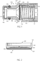
- FIGURE 1 is a partially fragmented, generally cross-sectional view of an embodiment of pressure regulator valve 100 employing seal 101 in accordance with the present invention.
- Fuel pressure regulator valve 100 is primarily comprised of housing 105 defining fuel passage 106 and seat 107.
- Pin 110 is disposed in housing 105.
- Pin 110 has raised conforming elastomeric embossment 101 that functions as a seal that contacts seat 107 when valve 100 is closed.
- Spring 112 disposed in the housing, biases pin 110 to maintain rubber embossment 101 in contact with seat 107 to maintain valve 100 closed until fuel pressure on the opposite side of pin 110, such as in fluid passage 106, overcomes tension in spring 112.
- Adjusting screw 115 or a similar mechanism, which may be disposed in housing 105, is used to adjust the biasing provided by spring 112.
- the embodiment shown in Figure 1 also employs inlet filter 118, which may be a nylon mesh screen 119, held in a nylon plastic housing, snapped onto valve housing 105.
- Such a filter screen typically has a mesh opening of between twenty and fifty microns.
- O-ring 120 may be fit onto housing 105 to provide a seal between the valve and it's mounting, which may be a fuel pump body or other fuel system structure, either in the fuel tank or elsewhere in the fuel system.
- the o-ring may typically be made from Fluoroelastomer (FKM) rubber, but any rubber that is compatible with the fuel being handled may be used.
- FKM Fluoroelastomer
- Housing body 105 preferably provides a flow path, between filter 118 and seal 101, such as fuel passage 106, and from seal 101 through flow discharge ports 122. Housing bore 124, above seal 101, operatively accommodates valve pin 110 and constrains the length of valve spring 112.
- pin 100 is contained axially in bore 124 of body 105.
- Housing 105 defines seal seat 107, which interfaces with seal 101 of pin 110.
- Housing 105 may be made of brass, optionally plated with nickel, or the like. However, most any non-corrosive metal, or other metal with an anti-corrosive coating, can be employed for housing 105. Alternatively, plastic construction, using moisture and fuel resistant plastics may be used.
- Figure 2 is an enlarged, more detailed , partially fragmented, generally cross-sectional, view of an embodiment of generally cylindrical pin 110, showing rubber seal 101 overmolded onto sealing annulus 230.
- Overmolded seal 101 may extend beyond annulus 230 and onto the bottom of flange 235.
- Flange 235 may align pin 110 in bore 124.
- Pin 110 also preferably defines recess 237, which may be generally circular, for mating with, and aligning pin 110 with, spring 112.
- pin 110 might define a boss or other structure protruding from pin 110 to mate with spring 112 and align it with pin 110.
- the relative thinness of overmolded rubber seal 101 over sealing annulus 230 provides repeatable and durable performance in the present valve.
- a relative shallow depth for annulus 230 may further facilitate this performance repeatability and durability.
- the thickness of seal 101, over annulus 230 is sufficiently thin to limit the total distention of the shape of seal 101 and any rubber swelling.
- the shape of seal 101 is maintained by the underlying reinforcing metal of annulus 230.
- Pin 110 may be nickel plated brass, although it may be made from any metal, with appropriate anti-corrosive properties or coating. Alternatively pin 110 may be made from plastic. Seal 101 may made from FKM, but other rubber compounds suitable for use with the fuel being handled may be used.
- spring 112 is held in compression between the top of pin 110 and adjusting screw 115.
- the spring may be stainless steel, but other spring materials that have suitable corrosion resistant properties with respect to the fuel being handled may be used.
- the spring may be a coil spring, as illustrated in Figure 1 , but it might also be an elastomeric structure of some sort or a cantilevered or conical spring.
- Valve opening pressure is calibrated by adjusting the axial position of screw 115 in threads 137 defined in body 105 until a correct spring force is applied to pin 110 to balance a desired fluid pressure below seal 101, providing a correct opening pressure for valve 100, after which screw 103 is locked in position.
- an upsetting tool or the like may be used to lock the threads between housing 105 and adjusting screw 115.
- the adjusting screw may be made of brass, with a nickel coating.
- most any non-corrosive metal or other metal with an anti-corrosive coating or plating could be used to make screw 115.
- a plastic construction, using moisture and fuel resistant plastics may be used.
- Other means of providing the adjustment rather than threads may also be used, as appropriate to the materials of construction and the assembly process.
- Figure 3 shows valve 100 open, with resulting linear streamlined flow, as indicated by flow arrows.
- the metal surface of seat 117, defined by the housing is flat and the raised annular ring is formed by a thin layer of rubber 101 molded over the metal sealing annulus 230.
- displacement or swelling that occurs in the rubber over time does not change the flow path in the valve.
- a thin section thickness for the rubber embossment limits the total distention of the shape, which is maintained by the underlying reinforcing metal.
- the valve begins to open the fluid flow will be straight, parallel to the metal surface of the housings seat, without any changes in direction or constraint through a contorted path. The result is lower pressure drop at the onset of flow.
- the present invention provides a fuel injection system a lower pressure drop as the pressure regulator valve actuates and a more linear pressure drop-versus-flow relationship across the span of fluid flow rates through which the pressure regulator valve operates.
- the reduced pressure drop improves the robustness of the fuel injector performance, as the fuel injectors are exposed to lower pressure excursions. This linear relationship improves the effectiveness of the fuel injection control system by increasing the predictability of the pressure drop.
- biasing force may, as diagrammatically depicted in Figure 4 , be applied by a mechanism (412) other than a spring or the like, and/or may, such as diagrammatically illustrated in Figure 5 , be adjusted by a mechanism (514) other than a manually adjusted screw or the like.
- FIG. 4 shows a partially fragmented view of regulator valve embodiment 400 of the present invention employing example 412 of a hydraulically actuated biasing mechanism.
- Illustrated hydraulically actuated biasing mechanism 412 might be locally controlled such as by a locally (or remotely) located hydraulic (or pneumatic) valve supplying fluidic pressure to mechanism 412.
- This control valve might, in turn, be controlled by a vehicle Engine Control Module (ECM), or the like, in a fuel injection system, or by a similar control mechanism in other systems employing valve 400.
- ECM Vehicle Engine Control Module
- Mechanism 412 which might take the form of a hydraulic (slave) cylinder, or the like, might bias pin 110, via push rod 415, to maintain rubber embossment 101 in contact with seat 107 to maintain valve 400 closed until fuel pressure on the opposite side of pin 110 overcomes the pressure exerted by cylinder 412.
- a hydraulic or pneumatic mechanism similar to mechanism 412 may be used to adjust the tension of a spring (112) in other embodiments of a pressure regulator valve (rather than replace it).
- Figure 5 shows a partially fragmented view of regulator valve embodiment 500 of the present invention employing example 515 of an electronically actuated bias adjustment mechanism.
- valve 500 the biasing force exerted by spring 112 is adjusted or regulated by an electrical stepper motor, or the like, generally illustrated as 517 in Figure 5 .
- stepper motor 517 might turn screw pintle 515 to adjust the tension in spring 112 and in turn the biasing spring 112 imparts to pin 110 to maintain rubber embossment 101 in contact with seat 107 and to maintain valve 100 closed until fuel pressure on the opposite side of pin 110 overcomes the tension imparted in spring 112.
- an electrical solenoid, or the like might be used to adjust bias in spring 112, rather than a stepper motor and pintle arrangement, as illustrated.
- bias pin 110 may be interchangeably used to bias pin 110 and/or to adjust the biasing force applied to pin 110 with these or other electronic mechanisms.
- Such embodiments can provide variation of biasing force in accordance with an automatic or programmed logic, such as might be used in a fuel injection system to provide an added, higher degree of engine control for environmental, emissions or power optimization.
Landscapes
- Engineering & Computer Science (AREA)
- General Engineering & Computer Science (AREA)
- Mechanical Engineering (AREA)
- Chemical & Material Sciences (AREA)
- Combustion & Propulsion (AREA)
- Fuel-Injection Apparatus (AREA)
- Safety Valves (AREA)
- Control Of Fluid Pressure (AREA)
- Lift Valve (AREA)
Description
- This invention relates generally to pressure relief and pressure regulating valves, and more particularly to valve seals that minimize pressure gain with increasing flow in pressure regulator valves and the like, specifically well suited for use in fuel injection and other systems where minimizing pressure increases with increasing flow is desirable for improved system performance.
- Internal combustion fuel injection systems typically require some form of pressure controlling device, either a pressure regulator or a pressure relief valve to maintain an appropriate fuel pressure at the injectors. Conventional fuel pressure relief valves and regulators utilize metal-to-metal seals in the pressure relief valve. The metal-to-metal sealing elements are resistive to surface depression of the adjacent sealing surfaces; resulting in a direct flow path with minimum pressure drop. However, the metal-to-metal seals are subject to high leakage rates as the two sealing surfaces are rigid, nonconforming and highly sensitive to the effects of contamination. One solution to this problem employs rubber sealing pressure regulator valves. Such fuel pressure regulator valves comprise a rubber sealing element which is held in intimate contact with a metal seat, the seat having a raised boss that contacts, and depresses into the surface of a planar rubber element. In such a traditional valve design the annular metal sealing surface contacts the relatively thick flat rubber pad to affect the valve seal. Because of the relative softness, and viscoelastic properties, of the rubber the metal ring causes a permanent indention into the rubber surface. This surface depression typically causes a permanent "compression set" in the rubber. As the valve begins to open, the fluid flow is constrained to conform to the complex channel defined by surface deformation in the rubber, which results in a labyrinth flow path as the pressure regulator valve begins to open. The long and convoluted flow path causes a significant pressure drop at initial valve opening.
- Metal-to-metal sealed devices are more expensive and have a higher leak rate than rubber sealing pressure regulator valves. Leakage is typically associated with increased difficulty starting the associated vehicle. However, conventional rubber sealing pressure relief valves and regulators have a greater pressure drop, and less linear flow characteristics. These liabilities limit the application or rubber sealing pressure regulator valves.
GB 1371514 DE 19913805 ,DE 10148960 ,WO 2006/052110 ,US 6,068,022 andUS 2008/0073605 each disclose examples of a valve having a elastomeric sealing element. - The present invention is directed to systems and methods which minimize the pressure drop in a pressure regulator valve during low flow conditions. The present invention provides a pressure regulator valve as claimed in claim 1, and a method of minimizing the pressure drop in a pressure regulator valve during low flow conditions as claimed in claim 10.
- The present invention reverses the arrangement of sealing elements in a rubber sealing pressure regulator valve, creating a raised boss in the rubber component that in contact with a planar metal seat. The metal seat, being resistant to "compression set", maintains a planar surface allowing a direct flow path that minimizes pressure drop of the flowing fuel.
- The present invention reduces the leakage of the pressure regulator valve when it is closed, compared to the conventional metal-to-metal pressure regulator valve seal. This reduced leakage is advantageous to the fuel injection system's ability to hold pressure while the vehicle is off.
- Thus, in accordance with various embodiments of the present invention a pressure regulator valve, such as a fuel pressure regulator valve, has a housing that defines a fluid passage and a flat seat disposed around an opening of the fluid passage. The housing also preferably has exit ports. A pin is preferably axially disposed in the housing. This pin has a raised conforming elastomeric embossment that contacts the seat when the valve is closed. According to the invention, the pin has a raised annulus over which the elastomeric embossment is molded. This elastomeric overmold may have a thickness in a range of about 0.0508 mm (0.002 inches) to about 0.508 mm (0.020 inches) in thickness, preferably about 0.1778 mm (0.007 inches) in thickness. The elastomer may be fluoroelastomer, a nitrile, or the like selected for its chemical stability when exposed to the fluid used in the system. The pin is preferably biased, such as through exertion of compressive spring force on the pin, to maintain the elastomer embossment in contact with the seat to maintain the valve closed and control an opening pressure of the valve. This biasing is preferably adjustable and may be provided by a spring disposed in the housing, in contact with the pin and an adjustment screw disposed in the housing to contact and adjust the biasing of the spring. The spring may be a coil spring, an elastomeric spring, cantilever spring arrangement, a conical spring or other similar biasing member.
- In operation, such embodiments of a pressure regulator valve provide a flow channel, with the flat seat defined around the flow channel. The raised conforming elastomeric embossment defined on the pin, such as by overmolding the annulus defined by the pin with an elastomeric material, is axially contained in the housing. The pin is preferably biased such that the embossment is in contact with the seat when the valve is closed and flow of fluid through and out of the pressure regulator valve housing is controlled through a level of the biasing. The fluid flows across the flat seat and between the flat seat and the embossment when the valve is open in such a manner that the flow is generally linear with streamlined flow characteristics.
- In accordance with embodiments of the present pressure regulator valve, a hydraulic mechanism or electrically actuated mechanism may be used to apply the biasing at a level directed by automatic or programmed logic. Similarly, in accordance with some embodiments, a hydraulic or electrically actuated mechanism might be employed to varying the tension in a biasing spring or the like according to automatic or programmed logic.
- With respect to pressure drop to flow, the present invention provides the fuel injection system, or the like in which it is deployed, a lower pressure drop as the pressure regulator valve actuates and a more linear pressure drop-versus-flow relationship across the span of fluid flow rates through which the pressure regulator valve operates. The reduced pressure drop improves the robustness of the fuel injector performance, as the fuel injectors are exposed to lower pressure excursions. This linear relationship improves the effectiveness of the fuel injection control system by increasing the predictability of the pressure drop.
- The reduced pressure drop provided by the present valve results in several advantages. First, the reduced pressure drop is itself an advantage. Secondly, since the flow path remains fundamentally unchanged as the flow is increased, the rate of change in pressure drop with flow is constant, improving the linearity of the flow-to-pressure drop relationship. And lastly, the pressure drop does not vary as the properties of the rubber change, either over time, as the valve ages, or between individual valves.
- The foregoing has outlined rather broadly the features and technical advantages of the present invention in order that the detailed description of the invention that follows may be better understood. Additional features and advantages of the invention will be described hereinafter which form the subject of the claims of the invention. It should be appreciated by those skilled in the art that the conception and specific embodiment disclosed may be readily utilized as a basis for modifying or designing other structures for carrying out the same purposes of the present invention.
- The novel features which are believed to be characteristic of the invention, both as to its organization and method of operation, together with further objects and advantages will be better understood from the following description when considered in connection with the accompanying figures. It is to be expressly understood, however, that each of the figures is provided for the purpose of illustration and description only and is not intended as a definition of the limits of the present invention.
- The accompanying drawings, which are incorporated in and form part of the specification in which like numerals designate like parts, illustrate embodiments of the present invention and together with the description, serve to explain the principles of the invention. In the drawings:
-
FIGURE 1 is a partially fragmented, generally cross-sectional view of an embodiment of a pressure regulator valve employing a seal in accordance with the present invention; -
FIGURE 2 is an enlarged, more detailed, partially fragmented, generally cross-sectional, view of an embodiment of a pin for use in accordance with the present invention; -
FIGURE 3 is a partially fragmented, generally cross-sectional view of the pressure regulator valve embodiment ofFIGURE 1 , showing the valve open, with resulting linear streamlined flow; -
FIGURE 4 is a partially fragmented, generally cross-sectional view of a regulator valve embodiment of the present invention employing an example of hydraulically actuated biasing mechanism; and -
FIGURE 5 is a partially fragmented, generally cross-sectional view of a regulator valve embodiment of the present invention employing an example of an electronically actuated bias adjustment mechanism. -
FIGURE 1 is a partially fragmented, generally cross-sectional view of an embodiment ofpressure regulator valve 100 employingseal 101 in accordance with the present invention. Fuelpressure regulator valve 100 is primarily comprised ofhousing 105 definingfuel passage 106 andseat 107. Pin 110 is disposed inhousing 105.Pin 110 has raised conformingelastomeric embossment 101 that functions as a seal that contacts seat 107 whenvalve 100 is closed.Spring 112, disposed in the housing, biases pin 110 to maintainrubber embossment 101 in contact withseat 107 to maintainvalve 100 closed until fuel pressure on the opposite side ofpin 110, such as influid passage 106, overcomes tension inspring 112. Adjustingscrew 115, or a similar mechanism, which may be disposed inhousing 105, is used to adjust the biasing provided byspring 112. The embodiment shown inFigure 1 also employsinlet filter 118, which may be anylon mesh screen 119, held in a nylon plastic housing, snapped ontovalve housing 105. Such a filter screen typically has a mesh opening of between twenty and fifty microns. O-ring 120 may be fit ontohousing 105 to provide a seal between the valve and it's mounting, which may be a fuel pump body or other fuel system structure, either in the fuel tank or elsewhere in the fuel system. The o-ring may typically be made from Fluoroelastomer (FKM) rubber, but any rubber that is compatible with the fuel being handled may be used. -
Housing body 105 preferably provides a flow path, betweenfilter 118 andseal 101, such asfuel passage 106, and fromseal 101 throughflow discharge ports 122. Housing bore 124, aboveseal 101, operatively accommodatesvalve pin 110 and constrains the length ofvalve spring 112. Preferably,pin 100 is contained axially inbore 124 ofbody 105.Housing 105 definesseal seat 107, which interfaces withseal 101 ofpin 110.Housing 105 may be made of brass, optionally plated with nickel, or the like. However, most any non-corrosive metal, or other metal with an anti-corrosive coating, can be employed forhousing 105. Alternatively, plastic construction, using moisture and fuel resistant plastics may be used. -
Figure 2 is an enlarged, more detailed , partially fragmented, generally cross-sectional, view of an embodiment of generallycylindrical pin 110, showingrubber seal 101 overmolded onto sealingannulus 230.Overmolded seal 101 may extend beyondannulus 230 and onto the bottom offlange 235.Flange 235 may alignpin 110 inbore 124. Pin 110 also preferably definesrecess 237, which may be generally circular, for mating with, and aligningpin 110 with,spring 112. Alternatively, pin 110 might define a boss or other structure protruding frompin 110 to mate withspring 112 and align it withpin 110. The relative thinness ofovermolded rubber seal 101 over sealingannulus 230 provides repeatable and durable performance in the present valve. A relative shallow depth forannulus 230 may further facilitate this performance repeatability and durability. Preferably, the thickness ofseal 101, overannulus 230 is sufficiently thin to limit the total distention of the shape ofseal 101 and any rubber swelling. Preferably the shape ofseal 101 is maintained by the underlying reinforcing metal ofannulus 230. -
Pin 110 may be nickel plated brass, although it may be made from any metal, with appropriate anti-corrosive properties or coating. Alternatively pin 110 may be made from plastic.Seal 101 may made from FKM, but other rubber compounds suitable for use with the fuel being handled may be used. - Returning to
Figure 1 ,spring 112 is held in compression between the top ofpin 110 and adjustingscrew 115. The spring may be stainless steel, but other spring materials that have suitable corrosion resistant properties with respect to the fuel being handled may be used. Furthermore, the spring may be a coil spring, as illustrated inFigure 1 , but it might also be an elastomeric structure of some sort or a cantilevered or conical spring. Valve opening pressure is calibrated by adjusting the axial position ofscrew 115 inthreads 137 defined inbody 105 until a correct spring force is applied to pin 110 to balance a desired fluid pressure belowseal 101, providing a correct opening pressure forvalve 100, after which screw 103 is locked in position. In the embodiment shown inFigure 1 , an upsetting tool or the like may be used to lock the threads betweenhousing 105 and adjustingscrew 115. However, other arrangements, such as a mechanical lock or adjustable pin, may be used. The adjusting screw may be made of brass, with a nickel coating. However, most any non-corrosive metal or other metal with an anti-corrosive coating or plating could be used to makescrew 115. Also, a plastic construction, using moisture and fuel resistant plastics may be used. Other means of providing the adjustment rather than threads may also be used, as appropriate to the materials of construction and the assembly process. - With attention directed to
Figure 3 , the arrangement of components in the present valve provides a substantially different flow path in contrast to the prior art.Figure 3 showsvalve 100 open, with resulting linear streamlined flow, as indicated by flow arrows. In the present arrangement the metal surface of seat 117, defined by the housing, is flat and the raised annular ring is formed by a thin layer ofrubber 101 molded over themetal sealing annulus 230. In such embodiments displacement or swelling that occurs in the rubber, over time does not change the flow path in the valve. Preferably a thin section thickness for the rubber embossment limits the total distention of the shape, which is maintained by the underlying reinforcing metal. As the valve begins to open the fluid flow will be straight, parallel to the metal surface of the housings seat, without any changes in direction or constraint through a contorted path. The result is lower pressure drop at the onset of flow. - With respect to pressure drop to flow, the present invention provides a fuel injection system a lower pressure drop as the pressure regulator valve actuates and a more linear pressure drop-versus-flow relationship across the span of fluid flow rates through which the pressure regulator valve operates. The reduced pressure drop improves the robustness of the fuel injector performance, as the fuel injectors are exposed to lower pressure excursions. This linear relationship improves the effectiveness of the fuel injection control system by increasing the predictability of the pressure drop.
- In certain embodiments of a pressure regulator valve, biasing force may, as diagrammatically depicted in
Figure 4 , be applied by a mechanism (412) other than a spring or the like, and/or may, such as diagrammatically illustrated inFigure 5 , be adjusted by a mechanism (514) other than a manually adjusted screw or the like. - For example,
Figure 4 shows a partially fragmented view ofregulator valve embodiment 400 of the present invention employing example 412 of a hydraulically actuated biasing mechanism. Illustrated hydraulically actuatedbiasing mechanism 412 might be locally controlled such as by a locally (or remotely) located hydraulic (or pneumatic) valve supplying fluidic pressure tomechanism 412. This control valve might, in turn, be controlled by a vehicle Engine Control Module (ECM), or the like, in a fuel injection system, or by a similar control mechanism in othersystems employing valve 400.Mechanism 412, which might take the form of a hydraulic (slave) cylinder, or the like, might biaspin 110, viapush rod 415, to maintainrubber embossment 101 in contact withseat 107 to maintainvalve 400 closed until fuel pressure on the opposite side ofpin 110 overcomes the pressure exerted bycylinder 412. Alternatively, a hydraulic or pneumatic mechanism similar tomechanism 412, may be used to adjust the tension of a spring (112) in other embodiments of a pressure regulator valve (rather than replace it). - As another example,
Figure 5 shows a partially fragmented view ofregulator valve embodiment 500 of the present invention employing example 515 of an electronically actuated bias adjustment mechanism. Invalve 500 the biasing force exerted byspring 112 is adjusted or regulated by an electrical stepper motor, or the like, generally illustrated as 517 inFigure 5 . In the illustrated example,stepper motor 517 might turnscrew pintle 515 to adjust the tension inspring 112 and in turn thebiasing spring 112 imparts to pin 110 to maintainrubber embossment 101 in contact withseat 107 and to maintainvalve 100 closed until fuel pressure on the opposite side ofpin 110 overcomes the tension imparted inspring 112. Alternatively, an electrical solenoid, or the like, might be used to adjust bias inspring 112, rather than a stepper motor and pintle arrangement, as illustrated. - These or other mechanisms for applying hydraulic pressure may be interchangeably used to
bias pin 110 and/or to adjust the biasing force applied to pin 110 with these or other electronic mechanisms. Regardless, such embodiments can provide variation of biasing force in accordance with an automatic or programmed logic, such as might be used in a fuel injection system to provide an added, higher degree of engine control for environmental, emissions or power optimization. - Although the present invention and its advantages have been described in detail, it should be understood that various changes, substitutions and alterations can be made herein without departing from the scope of the invention as defined by the appended claims. Moreover, the scope of the present application is not intended to be limited to the particular embodiments of the process, machine, manufacture, composition of matter, means, methods and steps described in the specification.
Claims (16)
- A pressure regulator valve (100) comprising:a housing (105) defining fluid passage (106) and a flat seat (107) disposed around an opening of said fluid passage, within said housing;a pin (110) disposed axially in said housing, said pin having a raised conforming elastomeric embossment (101) that contacts said seat when said valve is closed;means (112) for biasing said pin to maintain said elastomeric embossment in contact with said seat to maintain said valve closed and control an opening pressure of said valve; andmeans (115) for adjusting said biasing,
characterized in that said raised conforming elastomeric embossment (101) comprises a
raised annular ring formed by an elastomer molded over a raised annulus (230) of said pin,
said raised annular ring contacting said seat when said valve is closed. - The pressure regulator valve of claim 1, wherein said housing (105) further comprises exit ports (122).
- The pressure regulator valve of claim 1, wherein said means (112) for biasing comprises a spring disposed in the housing.
- The pressure regulator valve of claim 3, wherein said spring (112) is a coil spring.
- The pressure regulator valve of claim 1, wherein said means (112) for biasing comprises hydraulic means (412) for varying said biasing according to automatic or programmed logic.
- The pressure regulator valve of claim 1, wherein said means (112) for biasing comprises electrically actuated means (515) for varying said biasing according to automatic or programmed logic.
- The pressure regulator valve of claim 1, wherein said means (115) for adjusting comprises an adjustment screw disposed in the housing (105) to contact and adjust said biasing of said means (112) for biasing.
- The pressure regulator valve of claim 1, wherein said means (115) for adjusting comprises hydraulic means (412) for varying said biasing according to automatic or programmed logic.
- The pressure regulator valve of claim 1, wherein said means (115) for adjusting comprises electrically actuated means (515) for varying said biasing according to automatic or programmed logic.
- A method of minimizing the pressure drop in a pressure regulator valve during low flow conditions, the method comprising:providing a flow channel (106) in a pressure regulator valve housing (105);defining a flat seat (107) in said housing, around said flow channel;defining a raised conforming elastomeric embossment (101) on a pin (110);containing said pin axially in said housing;biasing said pin such that said embossment is in contact with said seat, when said valve is closed; andcontrolling flow of fluid through and out of said pressure regulator valve housing based on a level of said biasing, said fluid flowing across said flat seat and between said flat seat and said embossment when said valve is open, characterized in that said defining the raised conforming elastomeric embossment (101) involves forming a raised annular ring by providing said pin (110) with a raised annulus (230) and molding an elastomer over said raised annulus, said raised annular ring contacting said seat when said valve is closed.
- The method of claim 10, wherein said controlling comprises varying said level of biasing according to automatic or programmed logic.
- The pressure regulator valve of claim 1, or the method of claim 10, wherein said elastomeric material disposed over said annulus (230) is in a range of about 0.0508 mm (0.002 inches) in thickness to about 0.508 mm (0.020 inches) in thickness.
- The pressure regulator valve of claim 1, or the method of claim 10, wherein said elastomeric material disposed over said annulus is about 0.1778 mm (0.007 inches) in thickness.
- The pressure regulator valve of claim 1, or the method of claim 10, wherein said elastomer is a fluoroelastomer.
- The pressure regulator valve of claim 1, or the method of claim 10, wherein said elastomer is a nitrile.
- The pressure regulator valve of claim 1, wherein said pressure regulator valve (100) is a fuel pressure regulator valve.
Applications Claiming Priority (2)
| Application Number | Priority Date | Filing Date | Title |
|---|---|---|---|
| US12/590,696 US9328836B2 (en) | 2009-11-12 | 2009-11-12 | Pressure regulator valve seals, systems and methods |
| PCT/US2010/055633 WO2011059893A1 (en) | 2009-11-12 | 2010-11-05 | Pressure regulator valve seals, systems and methods |
Publications (2)
| Publication Number | Publication Date |
|---|---|
| EP2499405A1 EP2499405A1 (en) | 2012-09-19 |
| EP2499405B1 true EP2499405B1 (en) | 2019-07-03 |
Family
ID=43617951
Family Applications (1)
| Application Number | Title | Priority Date | Filing Date |
|---|---|---|---|
| EP10779873.8A Not-in-force EP2499405B1 (en) | 2009-11-12 | 2010-11-05 | Pressure regulator valve seals, systems and methods |
Country Status (10)
| Country | Link |
|---|---|
| US (1) | US9328836B2 (en) |
| EP (1) | EP2499405B1 (en) |
| JP (1) | JP2013511008A (en) |
| KR (1) | KR20120091355A (en) |
| CN (1) | CN102597586A (en) |
| BR (1) | BR112012009280A2 (en) |
| CA (1) | CA2777385A1 (en) |
| IN (1) | IN2012DN03149A (en) |
| MX (1) | MX2012004756A (en) |
| WO (1) | WO2011059893A1 (en) |
Families Citing this family (23)
| Publication number | Priority date | Publication date | Assignee | Title |
|---|---|---|---|---|
| US8210156B2 (en) * | 2009-07-01 | 2012-07-03 | Ford Global Technologies, Llc | Fuel system with electrically-controllable mechanical pressure regulator |
| US9328836B2 (en) * | 2009-11-12 | 2016-05-03 | Schrader Electronics Ltd. | Pressure regulator valve seals, systems and methods |
| EP2597034B1 (en) * | 2011-11-28 | 2015-11-04 | AIRBUS HELICOPTERS DEUTSCHLAND GmbH | Counterbalanced control stick system |
| JP6190580B2 (en) * | 2012-09-13 | 2017-08-30 | エドワーズ株式会社 | Rotary part of vacuum pump and vacuum pump |
| WO2014183173A1 (en) * | 2013-05-14 | 2014-11-20 | Atlas Copco Airpower, Naamloze Vennootschap | Minimum pressure valve |
| BE1022252B1 (en) * | 2013-05-14 | 2016-03-04 | Atlas Copco Airpower, Naamloze Vennootschap | MINIMUM PRESSURE VALVE |
| JP6095520B2 (en) * | 2013-08-20 | 2017-03-15 | 三菱電機株式会社 | Fuel supply device |
| DE202015106101U1 (en) * | 2015-11-11 | 2016-02-01 | Holger Blum | metering |
| DE202015106097U1 (en) * | 2015-11-11 | 2016-02-01 | Holger Blum | Conveyor for a vacuum distillation plant |
| DE202015106096U1 (en) * | 2015-11-11 | 2016-02-19 | Holger Blum | Pressure maintenance and control valve |
| JP6591270B2 (en) | 2015-11-30 | 2019-10-16 | 愛三工業株式会社 | Pressure regulating valve |
| US10080332B1 (en) * | 2016-07-29 | 2018-09-25 | Mjnn, Llc | Self-sealing dripper apparatus |
| KR20190057346A (en) * | 2016-09-21 | 2019-05-28 | 크노르-브렘제 시스테메 퓌어 누츠파조이게 게엠베하 | Minimum pressure valve for vehicles, especially for commercial screw compressors |
| CN106297913B (en) * | 2016-10-20 | 2023-09-15 | 中国船舶集团有限公司第七一八研究所 | Sealing structure capable of being automatically opened |
| CN107044369A (en) * | 2017-04-21 | 2017-08-15 | 上海中船三井造船柴油机有限公司 | Marine low speed diesel engine fuel oil supply system with pressure limiting and cushioning effect |
| CN107990032A (en) * | 2017-11-20 | 2018-05-04 | 余庆敏 | A kind of adjustable gas constant pressure valve |
| US10400911B2 (en) * | 2017-11-30 | 2019-09-03 | Sensata Technologies, Inc. | In-line fluid pressure regulator |
| AT16152U1 (en) * | 2018-03-01 | 2019-02-15 | Ing Andreas Zieger Dipl | Sealing system for valve |
| KR102195000B1 (en) * | 2019-04-30 | 2020-12-24 | 한국콘트롤공업 주식회사 | Relief Valve |
| CN113124158B (en) * | 2019-12-30 | 2022-04-22 | 中兴通讯股份有限公司 | Sealing assembly, shell and terminal equipment |
| KR102291256B1 (en) * | 2020-04-06 | 2021-08-20 | 주식회사 코아비스 | Fuel pump |
| JP7685201B2 (en) * | 2020-08-18 | 2025-05-29 | 株式会社荒井製作所 | Pressure Regulating Valve Device |
| KR20220125866A (en) | 2021-03-04 | 2022-09-15 | 삼성전자주식회사 | Vacuum valve and apparatus for fabricating semiconductor having the same |
Citations (1)
| Publication number | Priority date | Publication date | Assignee | Title |
|---|---|---|---|---|
| US20080073605A1 (en) * | 2006-09-25 | 2008-03-27 | Denso Corporation | Fluid-controlled valve |
Family Cites Families (27)
| Publication number | Priority date | Publication date | Assignee | Title |
|---|---|---|---|---|
| US2820474A (en) * | 1954-09-10 | 1958-01-21 | Anderson Greenwood & Co | Relief valve with high-pressure seal |
| US3438391A (en) * | 1964-01-13 | 1969-04-15 | Superior Valve & Fittings Co | Check valves having plastic sealing member |
| JPS5020261Y1 (en) * | 1969-11-20 | 1975-06-19 | ||
| JPS496232U (en) * | 1972-04-18 | 1974-01-19 | ||
| GB1371514A (en) | 1972-06-13 | 1974-10-23 | Alumasc Ltd | Safety relief valve for example for beverage-dispensing pressure- gas systems |
| DE3270633D1 (en) * | 1982-08-19 | 1986-05-22 | Vickers Systems Gmbh | Pressure-limiting apparatus |
| JPH01122567A (en) | 1987-11-06 | 1989-05-15 | Japan Synthetic Rubber Co Ltd | Manufacture of solid electrolyte sheet |
| JPH01122567U (en) * | 1988-02-15 | 1989-08-21 | ||
| JPH0332258U (en) * | 1989-08-08 | 1991-03-28 | ||
| US5113900A (en) * | 1991-01-30 | 1992-05-19 | Bridge Products, Inc. | Check valve with quick lock attachment feature |
| JP2580323Y2 (en) * | 1992-03-19 | 1998-09-10 | 高雄 山根 | valve |
| JP2000028010A (en) | 1998-07-14 | 2000-01-25 | Nok Corp | Valve device |
| DE19913805A1 (en) | 1999-03-26 | 2000-04-20 | Bosch Gmbh Robert | Pressure limitation and safety valve for fuel feed pumps has valve body formed by plate of elastomer material to give short construction length |
| DE19936843C2 (en) * | 1999-08-05 | 2002-08-14 | Bosch Gmbh Robert | Pressure control valve for a delivery module |
| US6068022A (en) * | 1999-08-25 | 2000-05-30 | Schrader-Bridgeport International, Inc. | Jet pump with improved control valve and pressure relief valve therefore |
| CN2403966Y (en) * | 2000-01-05 | 2000-11-01 | 熊磊 | Non-return valve |
| JP2001324246A (en) * | 2000-05-12 | 2001-11-22 | Zexel Valeo Climate Control Corp | Expansion valve and freezing cycle using it |
| US6311716B1 (en) * | 2000-09-05 | 2001-11-06 | John Blue Company | Fluid flow divider |
| DE10148960A1 (en) | 2000-10-06 | 2002-04-11 | Luk Fahrzeug Hydraulik | Pressure relief valve has cylindrical valve component and on side facing sealing seat has suitable recess by means of which insert with base element for elastomer coating is fitted |
| US6543745B1 (en) * | 2001-10-09 | 2003-04-08 | Halkey-Roberts Corporation | Male luer valve |
| US20030217770A1 (en) * | 2002-05-24 | 2003-11-27 | Schultz Jeffrey A. | Combination thermal and pressure relief valve |
| US7059582B2 (en) * | 2003-12-01 | 2006-06-13 | Societe Bic | Fuel cell supply having fuel compatible materials |
| CN101749215B (en) | 2004-11-12 | 2012-02-15 | Lg电子株式会社 | Discharge valve and valve assembly of reciprocating compressor having the same |
| JP4553698B2 (en) * | 2004-11-25 | 2010-09-29 | 藤倉ゴム工業株式会社 | Surface treatment composition, rubber surface treatment method, and relief valve manufacturing method |
| JP2007026056A (en) * | 2005-07-15 | 2007-02-01 | Toho Seisakusho:Kk | Fluid pressure regulator |
| JP2008138732A (en) * | 2006-11-30 | 2008-06-19 | Piolax Inc | Relief valve |
| US9328836B2 (en) * | 2009-11-12 | 2016-05-03 | Schrader Electronics Ltd. | Pressure regulator valve seals, systems and methods |
-
2009
- 2009-11-12 US US12/590,696 patent/US9328836B2/en not_active Expired - Fee Related
-
2010
- 2010-11-05 CA CA 2777385 patent/CA2777385A1/en not_active Abandoned
- 2010-11-05 JP JP2012538864A patent/JP2013511008A/en active Pending
- 2010-11-05 CN CN2010800510409A patent/CN102597586A/en active Pending
- 2010-11-05 EP EP10779873.8A patent/EP2499405B1/en not_active Not-in-force
- 2010-11-05 KR KR20127015055A patent/KR20120091355A/en not_active Ceased
- 2010-11-05 MX MX2012004756A patent/MX2012004756A/en not_active Application Discontinuation
- 2010-11-05 WO PCT/US2010/055633 patent/WO2011059893A1/en not_active Ceased
- 2010-11-05 BR BR112012009280A patent/BR112012009280A2/en not_active IP Right Cessation
- 2010-11-05 IN IN3149DEN2012 patent/IN2012DN03149A/en unknown
Patent Citations (1)
| Publication number | Priority date | Publication date | Assignee | Title |
|---|---|---|---|---|
| US20080073605A1 (en) * | 2006-09-25 | 2008-03-27 | Denso Corporation | Fluid-controlled valve |
Also Published As
| Publication number | Publication date |
|---|---|
| US20110108130A1 (en) | 2011-05-12 |
| EP2499405A1 (en) | 2012-09-19 |
| US9328836B2 (en) | 2016-05-03 |
| JP2013511008A (en) | 2013-03-28 |
| BR112012009280A2 (en) | 2016-06-07 |
| CN102597586A (en) | 2012-07-18 |
| IN2012DN03149A (en) | 2015-09-18 |
| WO2011059893A1 (en) | 2011-05-19 |
| CA2777385A1 (en) | 2011-05-19 |
| MX2012004756A (en) | 2012-06-08 |
| KR20120091355A (en) | 2012-08-17 |
Similar Documents
| Publication | Publication Date | Title |
|---|---|---|
| US9328836B2 (en) | Pressure regulator valve seals, systems and methods | |
| CN1107165C (en) | Adjustable matering valve for internal combustion engine fuel injector | |
| JP4842361B2 (en) | High pressure fuel pump | |
| US6554590B2 (en) | High pressure pump | |
| US8206131B2 (en) | Fuel pump | |
| US7114928B2 (en) | High-pressure fuel pump and assembly structure of high-pressure pump | |
| KR102691171B1 (en) | In-line fluid pressure regulator | |
| CN1111650C (en) | The electromagnetic fuel injector that internal-combustion engine is used | |
| US9453587B2 (en) | Flow rate adjusting device | |
| JP5984362B2 (en) | Proportional valve with improved sealing performance | |
| CZ2002569A3 (en) | Liquid control valve | |
| US20040061003A1 (en) | Fuel injection valve | |
| US20140311597A1 (en) | Compact Fuel Pressure Regulator | |
| WO2017167677A1 (en) | Check valve, check valve system and method for adjusting a check valve | |
| US20040069863A1 (en) | Fuel injection valve | |
| JP4690990B2 (en) | Air bypass device in fuel injection device | |
| CN111636987A (en) | a pressure limiting valve | |
| KR101719813B1 (en) | Injection valve | |
| CN216242414U (en) | An electric regulating valve | |
| DE19722061A1 (en) | Pressure control valve | |
| US20110284788A1 (en) | High Performance Miniature Regulator | |
| JPS639789A (en) | Solenoid valve for fluid control | |
| CN110671233A (en) | Gas pressure regulator for regulating gas pressure | |
| KR20150022438A (en) | Flow control valve | |
| MXPA06007991A (en) | Integrated post-guided seat ring assembly |
Legal Events
| Date | Code | Title | Description |
|---|---|---|---|
| PUAI | Public reference made under article 153(3) epc to a published international application that has entered the european phase |
Free format text: ORIGINAL CODE: 0009012 |
|
| 17P | Request for examination filed |
Effective date: 20120427 |
|
| AK | Designated contracting states |
Kind code of ref document: A1 Designated state(s): AL AT BE BG CH CY CZ DE DK EE ES FI FR GB GR HR HU IE IS IT LI LT LU LV MC MK MT NL NO PL PT RO RS SE SI SK SM TR |
|
| DAX | Request for extension of the european patent (deleted) | ||
| 17Q | First examination report despatched |
Effective date: 20130214 |
|
| STAA | Information on the status of an ep patent application or granted ep patent |
Free format text: STATUS: EXAMINATION IS IN PROGRESS |
|
| REG | Reference to a national code |
Ref country code: DE Ref legal event code: R079 Ref document number: 602010059854 Country of ref document: DE Free format text: PREVIOUS MAIN CLASS: F16K0015020000 Ipc: F16K0017060000 |
|
| GRAP | Despatch of communication of intention to grant a patent |
Free format text: ORIGINAL CODE: EPIDOSNIGR1 |
|
| STAA | Information on the status of an ep patent application or granted ep patent |
Free format text: STATUS: GRANT OF PATENT IS INTENDED |
|
| RIC1 | Information provided on ipc code assigned before grant |
Ipc: F02M 37/00 20060101ALI20190108BHEP Ipc: F16K 17/06 20060101AFI20190108BHEP |
|
| INTG | Intention to grant announced |
Effective date: 20190205 |
|
| GRAS | Grant fee paid |
Free format text: ORIGINAL CODE: EPIDOSNIGR3 |
|
| GRAA | (expected) grant |
Free format text: ORIGINAL CODE: 0009210 |
|
| STAA | Information on the status of an ep patent application or granted ep patent |
Free format text: STATUS: THE PATENT HAS BEEN GRANTED |
|
| AK | Designated contracting states |
Kind code of ref document: B1 Designated state(s): AL AT BE BG CH CY CZ DE DK EE ES FI FR GB GR HR HU IE IS IT LI LT LU LV MC MK MT NL NO PL PT RO RS SE SI SK SM TR |
|
| REG | Reference to a national code |
Ref country code: GB Ref legal event code: FG4D |
|
| REG | Reference to a national code |
Ref country code: CH Ref legal event code: EP Ref country code: AT Ref legal event code: REF Ref document number: 1151409 Country of ref document: AT Kind code of ref document: T Effective date: 20190715 |
|
| REG | Reference to a national code |
Ref country code: IE Ref legal event code: FG4D |
|
| REG | Reference to a national code |
Ref country code: DE Ref legal event code: R096 Ref document number: 602010059854 Country of ref document: DE |
|
| REG | Reference to a national code |
Ref country code: NL Ref legal event code: MP Effective date: 20190703 |
|
| REG | Reference to a national code |
Ref country code: LT Ref legal event code: MG4D |
|
| REG | Reference to a national code |
Ref country code: AT Ref legal event code: MK05 Ref document number: 1151409 Country of ref document: AT Kind code of ref document: T Effective date: 20190703 |
|
| PG25 | Lapsed in a contracting state [announced via postgrant information from national office to epo] |
Ref country code: LT Free format text: LAPSE BECAUSE OF FAILURE TO SUBMIT A TRANSLATION OF THE DESCRIPTION OR TO PAY THE FEE WITHIN THE PRESCRIBED TIME-LIMIT Effective date: 20190703 Ref country code: PT Free format text: LAPSE BECAUSE OF FAILURE TO SUBMIT A TRANSLATION OF THE DESCRIPTION OR TO PAY THE FEE WITHIN THE PRESCRIBED TIME-LIMIT Effective date: 20191104 Ref country code: NL Free format text: LAPSE BECAUSE OF FAILURE TO SUBMIT A TRANSLATION OF THE DESCRIPTION OR TO PAY THE FEE WITHIN THE PRESCRIBED TIME-LIMIT Effective date: 20190703 Ref country code: CZ Free format text: LAPSE BECAUSE OF FAILURE TO SUBMIT A TRANSLATION OF THE DESCRIPTION OR TO PAY THE FEE WITHIN THE PRESCRIBED TIME-LIMIT Effective date: 20190703 Ref country code: BG Free format text: LAPSE BECAUSE OF FAILURE TO SUBMIT A TRANSLATION OF THE DESCRIPTION OR TO PAY THE FEE WITHIN THE PRESCRIBED TIME-LIMIT Effective date: 20191003 Ref country code: SE Free format text: LAPSE BECAUSE OF FAILURE TO SUBMIT A TRANSLATION OF THE DESCRIPTION OR TO PAY THE FEE WITHIN THE PRESCRIBED TIME-LIMIT Effective date: 20190703 Ref country code: NO Free format text: LAPSE BECAUSE OF FAILURE TO SUBMIT A TRANSLATION OF THE DESCRIPTION OR TO PAY THE FEE WITHIN THE PRESCRIBED TIME-LIMIT Effective date: 20191003 Ref country code: AT Free format text: LAPSE BECAUSE OF FAILURE TO SUBMIT A TRANSLATION OF THE DESCRIPTION OR TO PAY THE FEE WITHIN THE PRESCRIBED TIME-LIMIT Effective date: 20190703 Ref country code: HR Free format text: LAPSE BECAUSE OF FAILURE TO SUBMIT A TRANSLATION OF THE DESCRIPTION OR TO PAY THE FEE WITHIN THE PRESCRIBED TIME-LIMIT Effective date: 20190703 Ref country code: FI Free format text: LAPSE BECAUSE OF FAILURE TO SUBMIT A TRANSLATION OF THE DESCRIPTION OR TO PAY THE FEE WITHIN THE PRESCRIBED TIME-LIMIT Effective date: 20190703 |
|
| PG25 | Lapsed in a contracting state [announced via postgrant information from national office to epo] |
Ref country code: IS Free format text: LAPSE BECAUSE OF FAILURE TO SUBMIT A TRANSLATION OF THE DESCRIPTION OR TO PAY THE FEE WITHIN THE PRESCRIBED TIME-LIMIT Effective date: 20191103 Ref country code: GR Free format text: LAPSE BECAUSE OF FAILURE TO SUBMIT A TRANSLATION OF THE DESCRIPTION OR TO PAY THE FEE WITHIN THE PRESCRIBED TIME-LIMIT Effective date: 20191004 Ref country code: LV Free format text: LAPSE BECAUSE OF FAILURE TO SUBMIT A TRANSLATION OF THE DESCRIPTION OR TO PAY THE FEE WITHIN THE PRESCRIBED TIME-LIMIT Effective date: 20190703 Ref country code: RS Free format text: LAPSE BECAUSE OF FAILURE TO SUBMIT A TRANSLATION OF THE DESCRIPTION OR TO PAY THE FEE WITHIN THE PRESCRIBED TIME-LIMIT Effective date: 20190703 Ref country code: ES Free format text: LAPSE BECAUSE OF FAILURE TO SUBMIT A TRANSLATION OF THE DESCRIPTION OR TO PAY THE FEE WITHIN THE PRESCRIBED TIME-LIMIT Effective date: 20190703 Ref country code: AL Free format text: LAPSE BECAUSE OF FAILURE TO SUBMIT A TRANSLATION OF THE DESCRIPTION OR TO PAY THE FEE WITHIN THE PRESCRIBED TIME-LIMIT Effective date: 20190703 |
|
| PG25 | Lapsed in a contracting state [announced via postgrant information from national office to epo] |
Ref country code: TR Free format text: LAPSE BECAUSE OF FAILURE TO SUBMIT A TRANSLATION OF THE DESCRIPTION OR TO PAY THE FEE WITHIN THE PRESCRIBED TIME-LIMIT Effective date: 20190703 |
|
| PG25 | Lapsed in a contracting state [announced via postgrant information from national office to epo] |
Ref country code: RO Free format text: LAPSE BECAUSE OF FAILURE TO SUBMIT A TRANSLATION OF THE DESCRIPTION OR TO PAY THE FEE WITHIN THE PRESCRIBED TIME-LIMIT Effective date: 20190703 Ref country code: DK Free format text: LAPSE BECAUSE OF FAILURE TO SUBMIT A TRANSLATION OF THE DESCRIPTION OR TO PAY THE FEE WITHIN THE PRESCRIBED TIME-LIMIT Effective date: 20190703 Ref country code: EE Free format text: LAPSE BECAUSE OF FAILURE TO SUBMIT A TRANSLATION OF THE DESCRIPTION OR TO PAY THE FEE WITHIN THE PRESCRIBED TIME-LIMIT Effective date: 20190703 Ref country code: IT Free format text: LAPSE BECAUSE OF FAILURE TO SUBMIT A TRANSLATION OF THE DESCRIPTION OR TO PAY THE FEE WITHIN THE PRESCRIBED TIME-LIMIT Effective date: 20190703 Ref country code: PL Free format text: LAPSE BECAUSE OF FAILURE TO SUBMIT A TRANSLATION OF THE DESCRIPTION OR TO PAY THE FEE WITHIN THE PRESCRIBED TIME-LIMIT Effective date: 20190703 |
|
| PG25 | Lapsed in a contracting state [announced via postgrant information from national office to epo] |
Ref country code: SK Free format text: LAPSE BECAUSE OF FAILURE TO SUBMIT A TRANSLATION OF THE DESCRIPTION OR TO PAY THE FEE WITHIN THE PRESCRIBED TIME-LIMIT Effective date: 20190703 Ref country code: SM Free format text: LAPSE BECAUSE OF FAILURE TO SUBMIT A TRANSLATION OF THE DESCRIPTION OR TO PAY THE FEE WITHIN THE PRESCRIBED TIME-LIMIT Effective date: 20190703 Ref country code: IS Free format text: LAPSE BECAUSE OF FAILURE TO SUBMIT A TRANSLATION OF THE DESCRIPTION OR TO PAY THE FEE WITHIN THE PRESCRIBED TIME-LIMIT Effective date: 20200224 |
|
| REG | Reference to a national code |
Ref country code: DE Ref legal event code: R097 Ref document number: 602010059854 Country of ref document: DE |
|
| REG | Reference to a national code |
Ref country code: CH Ref legal event code: PL |
|
| PLBE | No opposition filed within time limit |
Free format text: ORIGINAL CODE: 0009261 |
|
| STAA | Information on the status of an ep patent application or granted ep patent |
Free format text: STATUS: NO OPPOSITION FILED WITHIN TIME LIMIT |
|
| PG2D | Information on lapse in contracting state deleted |
Ref country code: IS |
|
| PG25 | Lapsed in a contracting state [announced via postgrant information from national office to epo] |
Ref country code: MC Free format text: LAPSE BECAUSE OF FAILURE TO SUBMIT A TRANSLATION OF THE DESCRIPTION OR TO PAY THE FEE WITHIN THE PRESCRIBED TIME-LIMIT Effective date: 20190703 Ref country code: LU Free format text: LAPSE BECAUSE OF NON-PAYMENT OF DUE FEES Effective date: 20191105 Ref country code: LI Free format text: LAPSE BECAUSE OF NON-PAYMENT OF DUE FEES Effective date: 20191130 Ref country code: CH Free format text: LAPSE BECAUSE OF NON-PAYMENT OF DUE FEES Effective date: 20191130 |
|
| 26N | No opposition filed |
Effective date: 20200603 |
|
| REG | Reference to a national code |
Ref country code: BE Ref legal event code: MM Effective date: 20191130 |
|
| PG25 | Lapsed in a contracting state [announced via postgrant information from national office to epo] |
Ref country code: SI Free format text: LAPSE BECAUSE OF FAILURE TO SUBMIT A TRANSLATION OF THE DESCRIPTION OR TO PAY THE FEE WITHIN THE PRESCRIBED TIME-LIMIT Effective date: 20190703 |
|
| PG25 | Lapsed in a contracting state [announced via postgrant information from national office to epo] |
Ref country code: IE Free format text: LAPSE BECAUSE OF NON-PAYMENT OF DUE FEES Effective date: 20191105 |
|
| PG25 | Lapsed in a contracting state [announced via postgrant information from national office to epo] |
Ref country code: BE Free format text: LAPSE BECAUSE OF NON-PAYMENT OF DUE FEES Effective date: 20191130 |
|
| PGFP | Annual fee paid to national office [announced via postgrant information from national office to epo] |
Ref country code: GB Payment date: 20201029 Year of fee payment: 11 Ref country code: DE Payment date: 20201013 Year of fee payment: 11 |
|
| PG25 | Lapsed in a contracting state [announced via postgrant information from national office to epo] |
Ref country code: CY Free format text: LAPSE BECAUSE OF FAILURE TO SUBMIT A TRANSLATION OF THE DESCRIPTION OR TO PAY THE FEE WITHIN THE PRESCRIBED TIME-LIMIT Effective date: 20190703 |
|
| PG25 | Lapsed in a contracting state [announced via postgrant information from national office to epo] |
Ref country code: HU Free format text: LAPSE BECAUSE OF FAILURE TO SUBMIT A TRANSLATION OF THE DESCRIPTION OR TO PAY THE FEE WITHIN THE PRESCRIBED TIME-LIMIT; INVALID AB INITIO Effective date: 20101105 Ref country code: MT Free format text: LAPSE BECAUSE OF FAILURE TO SUBMIT A TRANSLATION OF THE DESCRIPTION OR TO PAY THE FEE WITHIN THE PRESCRIBED TIME-LIMIT Effective date: 20190703 Ref country code: FR Free format text: LAPSE BECAUSE OF NON-PAYMENT OF DUE FEES Effective date: 20191202 |
|
| REG | Reference to a national code |
Ref country code: DE Ref legal event code: R119 Ref document number: 602010059854 Country of ref document: DE |
|
| PG25 | Lapsed in a contracting state [announced via postgrant information from national office to epo] |
Ref country code: MK Free format text: LAPSE BECAUSE OF FAILURE TO SUBMIT A TRANSLATION OF THE DESCRIPTION OR TO PAY THE FEE WITHIN THE PRESCRIBED TIME-LIMIT Effective date: 20190703 |
|
| GBPC | Gb: european patent ceased through non-payment of renewal fee |
Effective date: 20211105 |
|
| PG25 | Lapsed in a contracting state [announced via postgrant information from national office to epo] |
Ref country code: GB Free format text: LAPSE BECAUSE OF NON-PAYMENT OF DUE FEES Effective date: 20211105 Ref country code: DE Free format text: LAPSE BECAUSE OF NON-PAYMENT OF DUE FEES Effective date: 20220601 |