EP2499345B1 - Soupape à calage variable - Google Patents
Soupape à calage variable Download PDFInfo
- Publication number
- EP2499345B1 EP2499345B1 EP10829051.1A EP10829051A EP2499345B1 EP 2499345 B1 EP2499345 B1 EP 2499345B1 EP 10829051 A EP10829051 A EP 10829051A EP 2499345 B1 EP2499345 B1 EP 2499345B1
- Authority
- EP
- European Patent Office
- Prior art keywords
- pressure drop
- valve
- orifice
- flow
- inner spool
- Prior art date
- Legal status (The legal status is an assumption and is not a legal conclusion. Google has not performed a legal analysis and makes no representation as to the accuracy of the status listed.)
- Active
Links
- 239000000446 fuel Substances 0.000 claims description 44
- 238000004891 communication Methods 0.000 claims description 18
- 239000012530 fluid Substances 0.000 claims description 13
- 238000000034 method Methods 0.000 claims description 9
- 230000001105 regulatory effect Effects 0.000 claims description 5
- 230000000694 effects Effects 0.000 description 4
- 230000006870 function Effects 0.000 description 3
- 238000013459 approach Methods 0.000 description 2
- 238000002485 combustion reaction Methods 0.000 description 2
- 230000001276 controlling effect Effects 0.000 description 2
- 238000012986 modification Methods 0.000 description 2
- 230000004048 modification Effects 0.000 description 2
- 230000000332 continued effect Effects 0.000 description 1
- 230000001419 dependent effect Effects 0.000 description 1
- 238000013461 design Methods 0.000 description 1
- 230000036316 preload Effects 0.000 description 1
Images


Classifications
-
- F—MECHANICAL ENGINEERING; LIGHTING; HEATING; WEAPONS; BLASTING
- F02—COMBUSTION ENGINES; HOT-GAS OR COMBUSTION-PRODUCT ENGINE PLANTS
- F02C—GAS-TURBINE PLANTS; AIR INTAKES FOR JET-PROPULSION PLANTS; CONTROLLING FUEL SUPPLY IN AIR-BREATHING JET-PROPULSION PLANTS
- F02C7/00—Features, components parts, details or accessories, not provided for in, or of interest apart form groups F02C1/00 - F02C6/00; Air intakes for jet-propulsion plants
- F02C7/22—Fuel supply systems
- F02C7/232—Fuel valves; Draining valves or systems
-
- F—MECHANICAL ENGINEERING; LIGHTING; HEATING; WEAPONS; BLASTING
- F16—ENGINEERING ELEMENTS AND UNITS; GENERAL MEASURES FOR PRODUCING AND MAINTAINING EFFECTIVE FUNCTIONING OF MACHINES OR INSTALLATIONS; THERMAL INSULATION IN GENERAL
- F16K—VALVES; TAPS; COCKS; ACTUATING-FLOATS; DEVICES FOR VENTING OR AERATING
- F16K11/00—Multiple-way valves, e.g. mixing valves; Pipe fittings incorporating such valves
- F16K11/02—Multiple-way valves, e.g. mixing valves; Pipe fittings incorporating such valves with all movable sealing faces moving as one unit
- F16K11/06—Multiple-way valves, e.g. mixing valves; Pipe fittings incorporating such valves with all movable sealing faces moving as one unit comprising only sliding valves, i.e. sliding closure elements
- F16K11/065—Multiple-way valves, e.g. mixing valves; Pipe fittings incorporating such valves with all movable sealing faces moving as one unit comprising only sliding valves, i.e. sliding closure elements with linearly sliding closure members
- F16K11/07—Multiple-way valves, e.g. mixing valves; Pipe fittings incorporating such valves with all movable sealing faces moving as one unit comprising only sliding valves, i.e. sliding closure elements with linearly sliding closure members with cylindrical slides
- F16K11/0708—Multiple-way valves, e.g. mixing valves; Pipe fittings incorporating such valves with all movable sealing faces moving as one unit comprising only sliding valves, i.e. sliding closure elements with linearly sliding closure members with cylindrical slides comprising means to avoid jamming of the slide or means to modify the flow
-
- Y—GENERAL TAGGING OF NEW TECHNOLOGICAL DEVELOPMENTS; GENERAL TAGGING OF CROSS-SECTIONAL TECHNOLOGIES SPANNING OVER SEVERAL SECTIONS OF THE IPC; TECHNICAL SUBJECTS COVERED BY FORMER USPC CROSS-REFERENCE ART COLLECTIONS [XRACs] AND DIGESTS
- Y10—TECHNICAL SUBJECTS COVERED BY FORMER USPC
- Y10T—TECHNICAL SUBJECTS COVERED BY FORMER US CLASSIFICATION
- Y10T137/00—Fluid handling
- Y10T137/7722—Line condition change responsive valves
- Y10T137/7837—Direct response valves [i.e., check valve type]
- Y10T137/785—With retarder or dashpot
- Y10T137/7851—End of valve forms dashpot chamber
-
- Y—GENERAL TAGGING OF NEW TECHNOLOGICAL DEVELOPMENTS; GENERAL TAGGING OF CROSS-SECTIONAL TECHNOLOGIES SPANNING OVER SEVERAL SECTIONS OF THE IPC; TECHNICAL SUBJECTS COVERED BY FORMER USPC CROSS-REFERENCE ART COLLECTIONS [XRACs] AND DIGESTS
- Y10—TECHNICAL SUBJECTS COVERED BY FORMER USPC
- Y10T—TECHNICAL SUBJECTS COVERED BY FORMER US CLASSIFICATION
- Y10T137/00—Fluid handling
- Y10T137/7722—Line condition change responsive valves
- Y10T137/7837—Direct response valves [i.e., check valve type]
- Y10T137/7904—Reciprocating valves
- Y10T137/7922—Spring biased
- Y10T137/7925—Piston-type valves
-
- Y—GENERAL TAGGING OF NEW TECHNOLOGICAL DEVELOPMENTS; GENERAL TAGGING OF CROSS-SECTIONAL TECHNOLOGIES SPANNING OVER SEVERAL SECTIONS OF THE IPC; TECHNICAL SUBJECTS COVERED BY FORMER USPC CROSS-REFERENCE ART COLLECTIONS [XRACs] AND DIGESTS
- Y10—TECHNICAL SUBJECTS COVERED BY FORMER USPC
- Y10T—TECHNICAL SUBJECTS COVERED BY FORMER US CLASSIFICATION
- Y10T137/00—Fluid handling
- Y10T137/7722—Line condition change responsive valves
- Y10T137/7837—Direct response valves [i.e., check valve type]
- Y10T137/7904—Reciprocating valves
- Y10T137/7922—Spring biased
- Y10T137/7929—Spring coaxial with valve
- Y10T137/7931—Spring in inlet
Definitions
- This invention generally relates to pressurizing, metering, and check valves, and more particularly to pressurizing, metering, and check valves for use in fuel nozzles for turbine engines.
- nozzle flow In most operating conditions on a turbine engine, it is desirable to have every fuel nozzle flow an equal amount of fuel. Reducing nozzle to nozzle flow variation enables better control of local fuel-to-air ratios in the combustor and allows for uniform temperature distribution at the inlet to the turbine stage. Uniform fuel flow from nozzle to nozzle is accomplished by calibrating the nozzle's flow number (FN) at a key operating condition. The pressure drop of the nozzle is adjusted to be in a narrow range at a known flow. In most applications, the calibration point tends to be at a high flow, where the accuracy of flow from nozzle to nozzle is most critical.
- FN flow number
- Nozzle calibration is accomplished by adjusting the pressure drop of a flow restriction in the nozzle, which is typically in series with the tip restriction of the nozzle.
- This adjustable flow restriction in the nozzle is referred to as the calibration orifice. All nozzle flow typically passes through the calibration orifice and then the tip, which combine to give the nozzle its high-flow pressure drop characteristic.
- the design challenge then becomes controlling flow of the fuel nozzle at low flow conditions.
- the pressure drop in the nozzle can be very small and subject to variations caused by, e.g., check valves, head effect of the manifold, and other variations.
- Pressurizing valves also known as metering valves
- the metering valve does this by controlling the relationship between pressure rise and nozzle flow rate; the flow number of the valve is small at lower flows and increases as flow increases.
- FIG. 5 A functional schematic illustration of such a conventional fuel nozzle 101 having a metering valve 103 is shown in FIG. 5 .
- the conventional metering valve 103 includes a valve spring 105, an inner spool 107, and an outer sleeve 109.
- Fuel enters the metering valve manifold 111 through ports 113.
- the inner spool 107 begins to stroke to the right as shown in FIG. 5 .
- the inner spool 107 moves to the right in relation to outer sleeve 109, it opens metering port 115, which then allows fuel to flow through the orifice 117 and the tip restriction 119 and into the combustor.
- the metering valve 103 is always in regulation. This means that it is always balancing the spring force of the valve against the pressure drop of the valve.
- trace 121 illustrates the pressure drop across metering port 115
- trace 123 illustrates the pressure drop across the calibration orifice 117 and the tip restriction 119
- trace 125 illustrates the percentage of total pressure drop across the fuel nozzle 101 that is allocated to the metering port 115.
- the pressure drop across the metering port 115 (trace 121) is fairly constant over the entire nozzle flow range, i.e. it continues to add pressure drop to the nozzle 101, even at high flows. While the pressure drop of the valve 103 is key to operation at low flow, it is not required at high flow. In fact, the additional pressure drop of the metering valve 103 (see trace 121) adds variation to the precisely calibrated performance of the nozzle 101, thus increasing the flow variation from nozzle to nozzle (compared to a nozzle with no valve) at high flow rates.
- a pressurizing valve for use in a nozzle that is able to work normally (variable FN) at low flow, without adding additional variation to the critical calibrated high flow of the nozzle.
- the invention provides such a valve.
- US 5,544,480 describes a system for regulating the flow of fuel to a combustion chamber of an afterburner of a gas turbine engine.
- embodiments of the present invention provide a new and improved valve that overcomes one or more of the problems existing in the art. More particularly, embodiments of the present invention provide a new and improved valve for use, e.g., in a fuel nozzle. Still more particularly, embodiments of the present invention provide a valve that is configured to control flow at low flow rates while minimizing the effect of the valve at high flow rates. Still more particularly, embodiments of the present invention provide a valve that is configured to provide pressurizing, metering, and/or checking functions to control flow at low flow rates while minimizing the effect of the valve at high flow rates
- the pressure drop across the orifice acts on the inner spool such that the inner spool is pulled open.
- the pressure drop across the orifice aids an inlet pressure in opposing the bias force of the spring.
- variable performance valve further comprises a seal positioned to check the flow in the no flow state.
- the inner spool is held against the seal by the bias force until a threshold pressure at the fuel inlet is reached to thereby meter the flow.
- the bias force acts on the inner spool during the low flow and intermediate flow conditions to thereby pressurize the flow.
- the spring acts on the inner spool to vary an area of overlap between the first port and the annulus during the low flow and intermediate flow conditions.
- the spring does not act on the inner spool to vary an area of overlap between the first port and the annulus during the high flow conditions.
- a variable performance valve for regulating flow through a housing having an inlet and an outlet having an orifice and a tip restriction therein
- the outer sleeve held in fixed relation to the housing, the outer sleeve including a first port providing fluid communication between the inlet and the orifice, an inner spool slidably positioned in relation to the outer sleeve such that the inner spool blocks fluid communication between the inlet and the orifice in a no flow state and variably allows fluid communication between the inlet and the orifice as the inner spool is slidably repositioned relative to the outer sleeve, and a spring positioned in a manifold formed between the outer sleeve and the inner spool to provide a bias force to position the inner spool to the no flow state
- the outer sleeve further including a second port positioned to provide fluid communication between a point in the outlet between the orifice and the tip
- the pressure drop across the orifice acts on the inner spool such that the inner spool is pulled open.
- the pressure drop across the orifice aids an inlet pressure in opposing the bias force of the spring.
- variable performance valve comprises a seal positioned to check the flow in the no flow state.
- the inner spool is held against the seal by the spring until a pressure at the inlet overcomes the bias force to thereby meter the flow.
- the bias force acts on the inner spool during the low flow and intermediate flow conditions to thereby pressurize the flow.
- the spring acts on the inner spool to vary an area of overlap between the first port and the annulus during the low flow and intermediate flow conditions to pressurized the flow.
- the spring does not act on the inner spool to vary an area of overlap between the first port and the annulus during the high flow conditions.
- a method of regulating fuel flow through a nozzle comprising the step of providing a variable performance valve configured such that at low flow conditions a pressure drop across the valve is approximately equal to a pressure drop across a metering port, at intermediate flow conditions the pressure drop across the valve is a sum of the pressure drop across the metering port and a pressure drop across an orifice, and at high flow conditions the pressure drop across the valve is approximately equal to the pressure drop across the orifice.
- the method further comprises the step of configuring the valve such that the pressure drop across the orifice pulls the valve open.
- the method further comprises the step of configuring the valve such that the flow is checked when a pressure thereof is less than a bias force.
- the method further comprises the step configuring the valve such that the bias force pressurizes the flow during the low flow and intermediate flow conditions.
- variable performance valve includes a spring, an inner spool, and an outer sleeve.
- a port is provided in the spool such that, as the valve begins to stroke, the port area that is open to flow increases.
- the flow also is directed to an orifice that, in environments such as fuel nozzles, is used to calibrate the nozzle at high flow conditions.
- the port accounts for a majority of the pressure drop across the valve during low flow conditions. As flow is increased, a pressure drop across the orifice begins to have an effect on the positioning of the valve. Indeed, during high flow conditions the pressure drop across the valve becomes almost entirely a result of the pressure drop across the orifice. This pressure drop helps pull the valve open to increase the port area, thereby minimizing the differential pressure of the valve port.
- a channel and an additional port communicating fluid pressure to the backside of the inner valving spool member downstream of the orifice is provided. Pressure drop across the valve is controlled almost entirely by the variable area port during low flow conditions, and governed almost entirely by the orifice during high flow conditions.
- Such configurations may utilize a orifice in parallel with the valve, or may include the orifice along an axis of the valve.
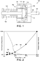
- FIG. 1 a fuel nozzle 100 including a variable performance valve 102 particularly well suited for application in a turbine engine.
- a fuel nozzle 100 including a variable performance valve 102 particularly well suited for application in a turbine engine.
- a variable performance valve 102 particularly well suited for application in a turbine engine.
- advantages of embodiments of this invention can be used to improve a variety of valve types, such as valves that only check flow, valves that only meter flow, or valves that may do both functions, for a variety of operating environments and applications.
- a fuel nozzle 100 for use in a turbine engine utilizes an embodiment of the variable performance valve 102 constructed in accordance with an embodiment of the present invention.
- the valve 102 may, or may not, include a seal 104 to check or prevent fuel flow at shut down.
- the valve 102 includes a spring 106, an inner spool or piston 108, and a fixed outer sleeve 110.
- a port 112 is arranged in relation to an annulus 114 of the outer sleeve 110 to act as a variable area based on the stroke of the valve 102, i.e. the position of the outer sleeve 110 in relation to the movement of the inner spool 108.
- This port 112 allows the fuel flow to pass through the valve 102 once opened. As illustrated, the fuel flows through port 112, into annulus 114, through a second port 116, and into a fuel valve manifold 118. The fuel flows through an orifice 120 (which may be the nozzle's calibration orifice in the illustrated operating environment) to create an additional pressure drop. The fuel then flows through the nozzle tip restriction 122 and into the combustion chamber of the turbine engine.
- orifice 120 which may be the nozzle's calibration orifice in the illustrated operating environment
- the valve 102 starts to open, i.e. the inner spool 108 moves to the right as pictured in FIG. 1 , and fuel starts to flow.
- the inlet to downstream pressure of the valve 102 is the initial spring force divided by the area of the spool 108 on which the pressure acts.
- Flow passes through the ports 112, 116 and also through the orifice 120.
- the orifice 120 does not cause any appreciable pressure drop based on its relative size compared to the area of opening of port 112.
- the pressure differential on the valve 102 is essentially equal to the pressure differential at the port 112 (port 116 being sized not to add appreciable pressure drop to the valve 102).
- valve 102 strokes open further, opening the port 112 to a larger area. This larger area allows more flow to pass. As the flow through the orifice 120 increases, a pressure drop develops across it. The pressure drop across the valve 102 is now a sum of the port 112 pressure drop and the orifice 120 pressure drop. Since the pressure drop across the valve 102 cannot be greater than the spring force divided by valve area, the valve 102 is forced to stroke open to reduce the port 112 pressure drop (by increasing flow area) to compensate for increasing orifice 120 pressure drop.
- valve 102 will stroke all the way open (preferably to a positive stop) such that the pressure drop at the port 112 becomes negligible and the pressure drop across the orifice 120 approaches 100% of the pressure drop across the valve 102. In this way, the additional pressure drop across the orifice 120 helps pull the valve 102 open.
- valve 103 When considering flow variation out of a conventional fuel nozzle 101 (see FIG. 5 ) utilizing a conventional metering valve 103, at very low flow the valve 103 variation dominates nozzle performance as shown by trace 125 of FIG. 6 .
- the valve 103 and the tip 119 and trim 117 restrictions combine, based on their respective pressure drops.
- the tip restriction 119 and calibration orifice 117 are dominant as shown by trace 123, but the valve 103 pressure drop is still present and adds tolerance to the flow performance due, e.g. to variations in spring force, etc. in the valve 103.
- This continued effect from the valve port 115 may be seen in FIG. 6 by the nearly constant pressure drop illustrated by trace 121.
- this valve 103 pressure drop at high flows adds to the nozzle-to-nozzle variation in the turbine engine, which is undesirable.
- variable performance valve 102 uses the orifice 120 pressure drop to pull the valve 102 open during high flow conditions, resulting in a port position independent of port pressure drop and such that the port 112 pressure drop is not significant.
- This change in nozzle flow dependence from low to high flow conditions may be graphically seen from an analysis of FIG. 2 and a comparison with the performance of the conventional metering valve 103 shown in FIG. 6 .
- trace 121 of FIG. 6 shows the continual pressure drop of the metering port 115 of the conventional metering valve 103 over the entire flow range.
- Trace 124 of FIG. 2 shows that the pressure drop of port 112 reduces as the flow increases.
- trace 126 illustrates that, at high flow conditions, nearly the entire pressure drop of the nozzle 100 is due to the tip restriction 122 and the orifice 120.
- the nozzle-to-nozzle variation in flow is dependent almost exclusively on the tip restriction 122 in combination with the orifice 120. Since the orifice 120 is calibrated in the exemplary environment of a nozzle 100 for a turbine engine, such variation can be minimized.
- FIG. 3 illustrates an alternate embodiment of a variable performance valve 102' in a nozzle 100'.
- the orifice 120' is positioned in parallel with the valve 102' and uses the downstream pressure of the orifice 120' to act on one side of the valve 102', i.e. on the opposite side of valving spool 108' on which the spring 106' also acts.
- the valve 102' begins to stroke, thereby opening port 112' to allow flow therethrough, and through the orifice 120' and the tip restriction 122.
- the flow also communicates through channel 132 and port 130 in the outer sleeve 110' to act on the opposite side of the valving spool 108'just indicated.
- valve 102' will stroke all the way open (preferably to a positive stop) such that the pressure drop at the port 112' becomes negligible and the pressure drop across the orifice 120' approaches 100% of the pressure drop across the valve 102'.
- FIG. 4 A further embodiment that incorporates the orifice 120" directly in the piston 108" of the valve 102", thus having all flow pass through the valve 102" on its axis, is shown in FIG. 4 .
- Flow is communicated to the orifice 120" via port 134 once the valve 102" begins to stroke open.
- the pressure of the downstream side of the orifice 120" acts on the backside of the piston 108" to provide operation as discussed above.
Landscapes
- Engineering & Computer Science (AREA)
- General Engineering & Computer Science (AREA)
- Chemical & Material Sciences (AREA)
- Combustion & Propulsion (AREA)
- Mechanical Engineering (AREA)
- Fuel-Injection Apparatus (AREA)
- Lift Valve (AREA)
Claims (15)
- Soupape à capacité variable (102) à utiliser dans un buse de carburant (100) pour un moteur à turbine, la buse de carburant comprenant un boîtier présentant une entrée de carburant et une sortie présentant une restriction d'extrémité (122) dans celle-ci, la soupape à capacité variable étant positionnée entre l'entrée et la restriction d'extrémité, comprenant:un manchon extérieur (110) maintenu en relation fixe sur le boîtier, le manchon extérieur comprenant un anneau (114) formé dans une surface intérieure de celui-ci,caractérisée en ce qu'elle comprend en outre une bobine intérieure (108) positionnée de façon coulissante par rapport au manchon extérieur, la bobine intérieure comprenant un premier port (112) positionné de manière à ne pas être en communication avec l'anneau dans un état de non écoulement de la buse et à venir en communication avec l'anneau lorsque la bobine intérieure est repositionnée de façon coulissante par rapport au manchon extérieur, la bobine intérieure comprenant en outre un second port (116) en communication avec l'anneau et un collecteur de carburant (118) de la bobine intérieure, la bobine intérieure comportant en outre un orifice pour établir une communication fluidique entre le collecteur de carburant et restriction d'extrémité de sortie, etun ressort (106) positionné de manière à générer une force de poussée pour positionner la bobine intérieure dans l'état de non écoulement, moyennant quoi le premier port n'est pas en communication fluidique avec l'anneau; etdans laquelle le premier port et l'orifice sont dimensionnés l'un par rapport à l'autre de telle sorte que dans des conditions de faible écoulement une chute de pression à partir de l'entrée jusqu'à la restriction d'extrémité soit approximativement égale à une chute de pression en travers du premier port, que dans des conditions d'écoulement intermédiaire la chute de pression à partir de l'entrée jusqu'à la restriction d'extrémité soit une somme de la chute de pression en travers du premier port et d'une chute de pression en travers de l'orifice, et que dans des conditions de fort écoulement la chute de pression à partir de l'entrée jusqu'à la restriction d'extrémité soit approximativement égale à la chute de pression en travers de l'orifice.
- Soupape à capacité variable selon la revendication 1, dans laquelle la chute de pression en travers de l'orifice agit sur la bobine intérieure de telle sorte que la bobine intérieure soit tirée en position ouverte.
- Soupape à capacité variable selon la revendication 1, dans laquelle la chute de pression en travers de l'orifice aide une pression d'entrée à s'opposer à la force de poussée du ressort.
- Soupape à capacité variable selon la revendication 1, comprenant en outre un joint positionné de manière à contrôler l'écoulement dans l'état de non écoulement.
- Soupape à capacité variable selon la revendication 4, dans laquelle la bobine intérieure est maintenue contre le joint par la force de poussée jusqu'à ce qu'une pression de seuil à l'entrée de carburant soit atteinte pour doser ainsi l'écoulement.
- Soupape à capacité variable selon la revendication 1, dans laquelle la force de poussée agit sur la bobine intérieure dans les conditions de faible écoulement et d'écoulement intermédiaire afin de pressuriser ainsi l'écoulement.
- Soupape à capacité variable (100') pour réguler l'écoulement à travers un boîtier présentant une entrée et une sortie comportant un orifice (120') et une restriction d'extrémité (122) dans celui-ci, caractérisée en ce qu'elle comprend en outre:un manchon extérieur (110') maintenu en relation fixe sur le boîtier, le manchon extérieur comportant un premier port (112') qui établit une communication fluidique entre l'entrée et l'orifice,une bobine intérieure (108') positionnée de façon coulissante par rapport au manchon extérieur de telle sorte que la bobine intérieure bloque la communication fluidique entre l'entrée et l'orifice dans un état de non écoulement et autorise de façon variable une communication fluidique entre l'entrée et l'orifice lorsque la bobine intérieure est repositionnée de façon coulissante par rapport au manchon extérieur, etun ressort (106') positionné dans un collecteur formé entre le manchon extérieur et la bobine intérieure afin de générer une force de poussée pour positionner la bobine intérieure dans l'état de non écoulement, le manchon extérieur comportant en outre un second port (130) positionné de manière à établir une communication fluidique entre un point dans la sortie entre l'orifice et la restriction d'extrémité et le collecteur; etdans laquelle, dans des conditions de faible écoulement, une chute de pression à partir de l'entrée jusqu'à la restriction d'extrémité est approximativement égale à une chute de pression en travers du premier port, dans des conditions d'écoulement intermédiaire, la chute de pression à partir de l'entrée jusqu'à la restriction d'extrémité est une somme de la chute de pression en travers du premier port et d'une chute de pression en travers de l'orifice, et dans des conditions de fort écoulement, la chute de pression à partir de l'entrée jusqu'à la restriction d'extrémité est approximativement égale à la chute de pression en travers de l'orifice.
- Soupape à capacité variable selon la revendication 7, dans laquelle la chute de pression en travers de l'orifice agit sur la bobine intérieure de telle sorte que la bobine intérieure soit tirée en position ouverte.
- Soupape à capacité variable selon la revendication 8, dans laquelle la chute de pression en travers de l'orifice aide une pression d'entrée à s'opposer à la force de poussée du ressort.
- Soupape à capacité variable selon la revendication 7, comprenant en outre un joint positionné de manière à contrôler l'écoulement dans l'état de non écoulement.
- Soupape à capacité variable selon la revendication 10, dans laquelle la bobine intérieure est maintenue contre le joint par le ressort jusqu'à ce qu'une pression à l'entrée dépasse la force de poussée afin de doser ainsi l'écoulement.
- Procédé de régulation d'un écoulement de carburant à travers une buse, comprenant l'étape de fourniture d'une soupape à capacité variable selon l'une quelconque des revendications 1 à 11, configurée de telle sorte que dans des conditions de faible écoulement, une chute de pression en travers de la soupape soit approximativement égale à une chute de pression en travers d'un port de dosage, que dans des conditions d'écoulement intermédiaire, la chute de pression en travers de la soupape soit une somme de la chute de pression en travers du port de dosage et d'une chute de pression en travers d'un orifice, et que dans des conditions de fort écoulement, la chute de pression en travers de la soupape soit approximativement égale à la chute de pression en travers de l'orifice.
- Procédé selon la revendication 12, comprenant en outre l'étape de configuration de la soupape de telle sorte que la chute de pression en travers de l'orifice tire la soupape en position ouverte.
- Procédé selon la revendication 12, comprenant en outre l'étape de configuration de la soupape de telle sorte que l'écoulement soit contrôlé lorsqu'une pression de celui-ci est inférieure à la force de poussée.
- Procédé selon la revendication 14, comprenant en outre l'étape de configuration de la soupape de telle sorte que la force de poussée pressurise l'écoulement dans les conditions de faible écoulement et d'écoulement intermédiaire.
Applications Claiming Priority (2)
| Application Number | Priority Date | Filing Date | Title |
|---|---|---|---|
| US12/614,567 US8393156B2 (en) | 2009-11-09 | 2009-11-09 | Variable performance valve of a fuel nozzle for a turbine engine |
| PCT/US2010/055349 WO2011056907A2 (fr) | 2009-11-09 | 2010-11-04 | Soupape à calage variable |
Publications (3)
| Publication Number | Publication Date |
|---|---|
| EP2499345A2 EP2499345A2 (fr) | 2012-09-19 |
| EP2499345A4 EP2499345A4 (fr) | 2016-05-11 |
| EP2499345B1 true EP2499345B1 (fr) | 2019-04-24 |
Family
ID=43970733
Family Applications (1)
| Application Number | Title | Priority Date | Filing Date |
|---|---|---|---|
| EP10829051.1A Active EP2499345B1 (fr) | 2009-11-09 | 2010-11-04 | Soupape à calage variable |
Country Status (5)
| Country | Link |
|---|---|
| US (1) | US8393156B2 (fr) |
| EP (1) | EP2499345B1 (fr) |
| CN (1) | CN102639843B (fr) |
| CA (1) | CA2780209C (fr) |
| WO (1) | WO2011056907A2 (fr) |
Families Citing this family (7)
| Publication number | Priority date | Publication date | Assignee | Title |
|---|---|---|---|---|
| US8646703B2 (en) | 2011-08-18 | 2014-02-11 | General Electric Company | Flow adjustment orifice systems for fuel nozzles |
| CN102865109B (zh) * | 2012-09-26 | 2015-03-25 | 中国神华能源股份有限公司 | 汽轮机的高压主汽门装置 |
| FR3014488B1 (fr) * | 2013-12-05 | 2018-10-19 | Safran Aircraft Engines | Vanne pour circuit carburant d'un moteur d'aeronef |
| US9856836B2 (en) | 2015-06-25 | 2018-01-02 | Woodward, Inc. | Variable fluid flow apparatus with integrated filter |
| CN113309613B (zh) * | 2021-05-25 | 2022-06-10 | 中国商用飞机有限责任公司 | 气体泄漏探测件、气体泄漏探测组件、引气管路结构和飞机 |
| US20230313742A1 (en) * | 2022-03-30 | 2023-10-05 | General Electric Company | Fuel nozzle valve seals for high temperature |
| US11994077B2 (en) | 2022-05-20 | 2024-05-28 | Woodward, Inc. | Fuel nozzle metering valve that provides dribble flow and related method |
Family Cites Families (25)
| Publication number | Priority date | Publication date | Assignee | Title |
|---|---|---|---|---|
| US2704035A (en) * | 1948-05-06 | 1955-03-15 | Nordberg Manufacturing Co | Injection pump for dual fuel engine |
| US2795106A (en) * | 1952-07-04 | 1957-06-11 | Rolls Royce | Liquid fuel systems |
| US2989975A (en) * | 1958-01-07 | 1961-06-27 | Bronzavia Sa | Valve regulating the pressure drop of a liquid flowing through an aperture having a variable crosssectional area, notably for a turbine machine regulator |
| US3465778A (en) * | 1966-08-08 | 1969-09-09 | Gen Electric | Combined pressure control valve and pressure relief valve having a flat pressure-flow characteristic |
| US3726088A (en) * | 1971-08-20 | 1973-04-10 | Us Navy | On-demand variable flow closed loop gas generator system with a variable area injector |
| US4586536A (en) * | 1983-07-18 | 1986-05-06 | General Motors Corporation | Flow control valve |
| US4825649A (en) | 1987-10-22 | 1989-05-02 | United Technologies Corporation | Shutoff and pressure regulating valve |
| US4962889A (en) | 1987-12-11 | 1990-10-16 | Fuel Systems Textron Inc. | Airblast fuel injection with adjustable valve cracking pressure |
| JPH0783335A (ja) * | 1993-09-14 | 1995-03-28 | Mitsubishi Heavy Ind Ltd | 流量制御弁 |
| JPH07259687A (ja) | 1994-03-16 | 1995-10-09 | Unisia Jecs Corp | 2流体噴射弁 |
| US5544480A (en) * | 1994-06-30 | 1996-08-13 | The United States Of America As Represented By The Secretary Of The Air Force | Augmentor light-off improvement |
| US5772182A (en) | 1996-04-17 | 1998-06-30 | United Technologies Corporation | Fuel flow control valve |
| US5918628A (en) | 1997-06-17 | 1999-07-06 | Parker-Hannifin Corporation | Multi-stage check valve |
| US6135135A (en) | 1997-12-12 | 2000-10-24 | Alliedsignal Inc. | Force balanced proportional bypass valve |
| US6092546A (en) * | 1997-12-12 | 2000-07-25 | Alliedsignal Inc. | Fuel flow divider and pressurizing valve for gas turbine |
| DE10020720A1 (de) * | 1999-04-30 | 2001-02-15 | Caterpillar Inc | Reaktionskammerisolationsrückschlagventil und Gasbrennstoffmotor, der dieses verwendet |
| US6637723B1 (en) * | 2001-09-06 | 2003-10-28 | Entegris, Inc. | Fluid valve |
| US6751939B2 (en) * | 2002-06-25 | 2004-06-22 | Honeywell International Inc. | Flow divider and ecology valve |
| US6877306B2 (en) * | 2003-02-07 | 2005-04-12 | Woodward Governor Company | Nozzle assembly with flow divider and ecology valve |
| US7007476B2 (en) | 2003-04-11 | 2006-03-07 | Parker-Hannifin Corporation | Gas turbine fuel system staging valves |
| JP2005105923A (ja) | 2003-09-30 | 2005-04-21 | Bosch Automotive Systems Corp | 燃料噴射弁 |
| US7464532B2 (en) * | 2005-10-25 | 2008-12-16 | Woodward Governor Company | Apparatus for elimination of transient pressure spikes on stiff fluid systems |
| GB0700511D0 (en) * | 2007-01-11 | 2007-02-21 | Goodrich Control Sys Ltd | Fuel System |
| GB2460634B (en) * | 2008-06-02 | 2010-07-07 | Rolls Royce Plc | Combustion apparatus |
| US8348630B2 (en) * | 2008-08-18 | 2013-01-08 | Woodward, Inc. | Flow compensated proportional bypass valve combined with a control valve |
-
2009
- 2009-11-09 US US12/614,567 patent/US8393156B2/en active Active
-
2010
- 2010-11-04 CN CN201080050578.8A patent/CN102639843B/zh active Active
- 2010-11-04 CA CA2780209A patent/CA2780209C/fr active Active
- 2010-11-04 WO PCT/US2010/055349 patent/WO2011056907A2/fr active Application Filing
- 2010-11-04 EP EP10829051.1A patent/EP2499345B1/fr active Active
Non-Patent Citations (1)
| Title |
|---|
| None * |
Also Published As
| Publication number | Publication date |
|---|---|
| CA2780209A1 (fr) | 2011-05-12 |
| EP2499345A4 (fr) | 2016-05-11 |
| US20110107768A1 (en) | 2011-05-12 |
| US8393156B2 (en) | 2013-03-12 |
| WO2011056907A2 (fr) | 2011-05-12 |
| CN102639843A (zh) | 2012-08-15 |
| EP2499345A2 (fr) | 2012-09-19 |
| CA2780209C (fr) | 2017-08-29 |
| CN102639843B (zh) | 2015-01-07 |
| WO2011056907A3 (fr) | 2011-09-29 |
Similar Documents
| Publication | Publication Date | Title |
|---|---|---|
| EP2499345B1 (fr) | Soupape à calage variable | |
| US8291707B2 (en) | Multi-stage check valve | |
| US6981359B2 (en) | Centrifugal pump fuel system and method for gas turbine engine | |
| US9574448B2 (en) | Split control unit | |
| US7063100B2 (en) | Flow regulator with pressure relief combination valve | |
| US8590310B2 (en) | Passive equilization flow divider valve | |
| EP4013957B1 (fr) | Gicleur de combustible à tolérance à l'écoulement réduite | |
| WO1999030019A1 (fr) | Diviseur de debit programme par soupape de mise en pression | |
| US7841841B2 (en) | Flow prioritizing valve system | |
| US6644031B2 (en) | Fuel injector with an optimized metering device | |
| US9709184B2 (en) | Control valve | |
| US6901953B2 (en) | Fuel metering device for a turbomachine injector | |
| US10591066B2 (en) | Pressure regulator | |
| WO2019177154A1 (fr) | Soupape de décharge | |
| US10663987B2 (en) | Pressure regulator | |
| US11994076B2 (en) | Multi-step pressurizing valve system | |
| US10458335B2 (en) | Minimum pressure shut-off valve | |
| US20140130915A1 (en) | Low hysteresis fluid metering valve |
Legal Events
| Date | Code | Title | Description |
|---|---|---|---|
| PUAI | Public reference made under article 153(3) epc to a published international application that has entered the european phase |
Free format text: ORIGINAL CODE: 0009012 |
|
| 17P | Request for examination filed |
Effective date: 20120531 |
|
| AK | Designated contracting states |
Kind code of ref document: A2 Designated state(s): AL AT BE BG CH CY CZ DE DK EE ES FI FR GB GR HR HU IE IS IT LI LT LU LV MC MK MT NL NO PL PT RO RS SE SI SK SM TR |
|
| DAX | Request for extension of the european patent (deleted) | ||
| A4 | Supplementary search report drawn up and despatched |
Effective date: 20160411 |
|
| RIC1 | Information provided on ipc code assigned before grant |
Ipc: F02C 7/22 20060101ALI20160405BHEP Ipc: F02C 7/232 20060101AFI20160405BHEP Ipc: F16K 11/07 20060101ALI20160405BHEP |
|
| RAP1 | Party data changed (applicant data changed or rights of an application transferred) |
Owner name: WOODWARD, INC. |
|
| STAA | Information on the status of an ep patent application or granted ep patent |
Free format text: STATUS: EXAMINATION IS IN PROGRESS |
|
| 17Q | First examination report despatched |
Effective date: 20170829 |
|
| GRAP | Despatch of communication of intention to grant a patent |
Free format text: ORIGINAL CODE: EPIDOSNIGR1 |
|
| STAA | Information on the status of an ep patent application or granted ep patent |
Free format text: STATUS: GRANT OF PATENT IS INTENDED |
|
| INTG | Intention to grant announced |
Effective date: 20180927 |
|
| GRAS | Grant fee paid |
Free format text: ORIGINAL CODE: EPIDOSNIGR3 |
|
| GRAA | (expected) grant |
Free format text: ORIGINAL CODE: 0009210 |
|
| STAA | Information on the status of an ep patent application or granted ep patent |
Free format text: STATUS: THE PATENT HAS BEEN GRANTED |
|
| AK | Designated contracting states |
Kind code of ref document: B1 Designated state(s): AL AT BE BG CH CY CZ DE DK EE ES FI FR GB GR HR HU IE IS IT LI LT LU LV MC MK MT NL NO PL PT RO RS SE SI SK SM TR |
|
| REG | Reference to a national code |
Ref country code: GB Ref legal event code: FG4D |
|
| REG | Reference to a national code |
Ref country code: CH Ref legal event code: EP |
|
| REG | Reference to a national code |
Ref country code: AT Ref legal event code: REF Ref document number: 1124444 Country of ref document: AT Kind code of ref document: T Effective date: 20190515 Ref country code: IE Ref legal event code: FG4D |
|
| REG | Reference to a national code |
Ref country code: DE Ref legal event code: R096 Ref document number: 602010058469 Country of ref document: DE |
|
| REG | Reference to a national code |
Ref country code: NL Ref legal event code: MP Effective date: 20190424 |
|
| REG | Reference to a national code |
Ref country code: LT Ref legal event code: MG4D |
|
| PG25 | Lapsed in a contracting state [announced via postgrant information from national office to epo] |
Ref country code: NL Free format text: LAPSE BECAUSE OF FAILURE TO SUBMIT A TRANSLATION OF THE DESCRIPTION OR TO PAY THE FEE WITHIN THE PRESCRIBED TIME-LIMIT Effective date: 20190424 |
|
| PG25 | Lapsed in a contracting state [announced via postgrant information from national office to epo] |
Ref country code: LT Free format text: LAPSE BECAUSE OF FAILURE TO SUBMIT A TRANSLATION OF THE DESCRIPTION OR TO PAY THE FEE WITHIN THE PRESCRIBED TIME-LIMIT Effective date: 20190424 Ref country code: HR Free format text: LAPSE BECAUSE OF FAILURE TO SUBMIT A TRANSLATION OF THE DESCRIPTION OR TO PAY THE FEE WITHIN THE PRESCRIBED TIME-LIMIT Effective date: 20190424 Ref country code: FI Free format text: LAPSE BECAUSE OF FAILURE TO SUBMIT A TRANSLATION OF THE DESCRIPTION OR TO PAY THE FEE WITHIN THE PRESCRIBED TIME-LIMIT Effective date: 20190424 Ref country code: AL Free format text: LAPSE BECAUSE OF FAILURE TO SUBMIT A TRANSLATION OF THE DESCRIPTION OR TO PAY THE FEE WITHIN THE PRESCRIBED TIME-LIMIT Effective date: 20190424 Ref country code: SE Free format text: LAPSE BECAUSE OF FAILURE TO SUBMIT A TRANSLATION OF THE DESCRIPTION OR TO PAY THE FEE WITHIN THE PRESCRIBED TIME-LIMIT Effective date: 20190424 Ref country code: PT Free format text: LAPSE BECAUSE OF FAILURE TO SUBMIT A TRANSLATION OF THE DESCRIPTION OR TO PAY THE FEE WITHIN THE PRESCRIBED TIME-LIMIT Effective date: 20190824 Ref country code: NO Free format text: LAPSE BECAUSE OF FAILURE TO SUBMIT A TRANSLATION OF THE DESCRIPTION OR TO PAY THE FEE WITHIN THE PRESCRIBED TIME-LIMIT Effective date: 20190724 Ref country code: ES Free format text: LAPSE BECAUSE OF FAILURE TO SUBMIT A TRANSLATION OF THE DESCRIPTION OR TO PAY THE FEE WITHIN THE PRESCRIBED TIME-LIMIT Effective date: 20190424 |
|
| PG25 | Lapsed in a contracting state [announced via postgrant information from national office to epo] |
Ref country code: GR Free format text: LAPSE BECAUSE OF FAILURE TO SUBMIT A TRANSLATION OF THE DESCRIPTION OR TO PAY THE FEE WITHIN THE PRESCRIBED TIME-LIMIT Effective date: 20190725 Ref country code: RS Free format text: LAPSE BECAUSE OF FAILURE TO SUBMIT A TRANSLATION OF THE DESCRIPTION OR TO PAY THE FEE WITHIN THE PRESCRIBED TIME-LIMIT Effective date: 20190424 Ref country code: BG Free format text: LAPSE BECAUSE OF FAILURE TO SUBMIT A TRANSLATION OF THE DESCRIPTION OR TO PAY THE FEE WITHIN THE PRESCRIBED TIME-LIMIT Effective date: 20190724 Ref country code: LV Free format text: LAPSE BECAUSE OF FAILURE TO SUBMIT A TRANSLATION OF THE DESCRIPTION OR TO PAY THE FEE WITHIN THE PRESCRIBED TIME-LIMIT Effective date: 20190424 Ref country code: PL Free format text: LAPSE BECAUSE OF FAILURE TO SUBMIT A TRANSLATION OF THE DESCRIPTION OR TO PAY THE FEE WITHIN THE PRESCRIBED TIME-LIMIT Effective date: 20190424 |
|
| REG | Reference to a national code |
Ref country code: AT Ref legal event code: MK05 Ref document number: 1124444 Country of ref document: AT Kind code of ref document: T Effective date: 20190424 |
|
| PG25 | Lapsed in a contracting state [announced via postgrant information from national office to epo] |
Ref country code: IS Free format text: LAPSE BECAUSE OF FAILURE TO SUBMIT A TRANSLATION OF THE DESCRIPTION OR TO PAY THE FEE WITHIN THE PRESCRIBED TIME-LIMIT Effective date: 20190824 |
|
| REG | Reference to a national code |
Ref country code: DE Ref legal event code: R097 Ref document number: 602010058469 Country of ref document: DE |
|
| PG25 | Lapsed in a contracting state [announced via postgrant information from national office to epo] |
Ref country code: EE Free format text: LAPSE BECAUSE OF FAILURE TO SUBMIT A TRANSLATION OF THE DESCRIPTION OR TO PAY THE FEE WITHIN THE PRESCRIBED TIME-LIMIT Effective date: 20190424 Ref country code: AT Free format text: LAPSE BECAUSE OF FAILURE TO SUBMIT A TRANSLATION OF THE DESCRIPTION OR TO PAY THE FEE WITHIN THE PRESCRIBED TIME-LIMIT Effective date: 20190424 Ref country code: DK Free format text: LAPSE BECAUSE OF FAILURE TO SUBMIT A TRANSLATION OF THE DESCRIPTION OR TO PAY THE FEE WITHIN THE PRESCRIBED TIME-LIMIT Effective date: 20190424 Ref country code: SK Free format text: LAPSE BECAUSE OF FAILURE TO SUBMIT A TRANSLATION OF THE DESCRIPTION OR TO PAY THE FEE WITHIN THE PRESCRIBED TIME-LIMIT Effective date: 20190424 Ref country code: RO Free format text: LAPSE BECAUSE OF FAILURE TO SUBMIT A TRANSLATION OF THE DESCRIPTION OR TO PAY THE FEE WITHIN THE PRESCRIBED TIME-LIMIT Effective date: 20190424 Ref country code: CZ Free format text: LAPSE BECAUSE OF FAILURE TO SUBMIT A TRANSLATION OF THE DESCRIPTION OR TO PAY THE FEE WITHIN THE PRESCRIBED TIME-LIMIT Effective date: 20190424 |
|
| PG25 | Lapsed in a contracting state [announced via postgrant information from national office to epo] |
Ref country code: SM Free format text: LAPSE BECAUSE OF FAILURE TO SUBMIT A TRANSLATION OF THE DESCRIPTION OR TO PAY THE FEE WITHIN THE PRESCRIBED TIME-LIMIT Effective date: 20190424 Ref country code: IT Free format text: LAPSE BECAUSE OF FAILURE TO SUBMIT A TRANSLATION OF THE DESCRIPTION OR TO PAY THE FEE WITHIN THE PRESCRIBED TIME-LIMIT Effective date: 20190424 |
|
| PLBE | No opposition filed within time limit |
Free format text: ORIGINAL CODE: 0009261 |
|
| STAA | Information on the status of an ep patent application or granted ep patent |
Free format text: STATUS: NO OPPOSITION FILED WITHIN TIME LIMIT |
|
| PG25 | Lapsed in a contracting state [announced via postgrant information from national office to epo] |
Ref country code: TR Free format text: LAPSE BECAUSE OF FAILURE TO SUBMIT A TRANSLATION OF THE DESCRIPTION OR TO PAY THE FEE WITHIN THE PRESCRIBED TIME-LIMIT Effective date: 20190424 |
|
| 26N | No opposition filed |
Effective date: 20200127 |
|
| PG25 | Lapsed in a contracting state [announced via postgrant information from national office to epo] |
Ref country code: SI Free format text: LAPSE BECAUSE OF FAILURE TO SUBMIT A TRANSLATION OF THE DESCRIPTION OR TO PAY THE FEE WITHIN THE PRESCRIBED TIME-LIMIT Effective date: 20190424 |
|
| REG | Reference to a national code |
Ref country code: CH Ref legal event code: PL |
|
| PG25 | Lapsed in a contracting state [announced via postgrant information from national office to epo] |
Ref country code: LU Free format text: LAPSE BECAUSE OF NON-PAYMENT OF DUE FEES Effective date: 20191104 Ref country code: MC Free format text: LAPSE BECAUSE OF FAILURE TO SUBMIT A TRANSLATION OF THE DESCRIPTION OR TO PAY THE FEE WITHIN THE PRESCRIBED TIME-LIMIT Effective date: 20190424 Ref country code: LI Free format text: LAPSE BECAUSE OF NON-PAYMENT OF DUE FEES Effective date: 20191130 Ref country code: CH Free format text: LAPSE BECAUSE OF NON-PAYMENT OF DUE FEES Effective date: 20191130 |
|
| REG | Reference to a national code |
Ref country code: BE Ref legal event code: MM Effective date: 20191130 |
|
| GBPC | Gb: european patent ceased through non-payment of renewal fee |
Effective date: 20191104 |
|
| PG25 | Lapsed in a contracting state [announced via postgrant information from national office to epo] |
Ref country code: IE Free format text: LAPSE BECAUSE OF NON-PAYMENT OF DUE FEES Effective date: 20191104 Ref country code: GB Free format text: LAPSE BECAUSE OF NON-PAYMENT OF DUE FEES Effective date: 20191104 Ref country code: FR Free format text: LAPSE BECAUSE OF NON-PAYMENT OF DUE FEES Effective date: 20191130 |
|
| PG25 | Lapsed in a contracting state [announced via postgrant information from national office to epo] |
Ref country code: BE Free format text: LAPSE BECAUSE OF NON-PAYMENT OF DUE FEES Effective date: 20191130 |
|
| PG25 | Lapsed in a contracting state [announced via postgrant information from national office to epo] |
Ref country code: CY Free format text: LAPSE BECAUSE OF FAILURE TO SUBMIT A TRANSLATION OF THE DESCRIPTION OR TO PAY THE FEE WITHIN THE PRESCRIBED TIME-LIMIT Effective date: 20190424 |
|
| PG25 | Lapsed in a contracting state [announced via postgrant information from national office to epo] |
Ref country code: HU Free format text: LAPSE BECAUSE OF FAILURE TO SUBMIT A TRANSLATION OF THE DESCRIPTION OR TO PAY THE FEE WITHIN THE PRESCRIBED TIME-LIMIT; INVALID AB INITIO Effective date: 20101104 Ref country code: MT Free format text: LAPSE BECAUSE OF FAILURE TO SUBMIT A TRANSLATION OF THE DESCRIPTION OR TO PAY THE FEE WITHIN THE PRESCRIBED TIME-LIMIT Effective date: 20190424 |
|
| PG25 | Lapsed in a contracting state [announced via postgrant information from national office to epo] |
Ref country code: MK Free format text: LAPSE BECAUSE OF FAILURE TO SUBMIT A TRANSLATION OF THE DESCRIPTION OR TO PAY THE FEE WITHIN THE PRESCRIBED TIME-LIMIT Effective date: 20190424 |
|
| PGFP | Annual fee paid to national office [announced via postgrant information from national office to epo] |
Ref country code: DE Payment date: 20231129 Year of fee payment: 14 |