EP2498615B1 - Dichtung, vorrichtung und verfahren zur anordnung einer derartigen dichtung - Google Patents
Dichtung, vorrichtung und verfahren zur anordnung einer derartigen dichtung Download PDFInfo
- Publication number
- EP2498615B1 EP2498615B1 EP10782440.1A EP10782440A EP2498615B1 EP 2498615 B1 EP2498615 B1 EP 2498615B1 EP 10782440 A EP10782440 A EP 10782440A EP 2498615 B1 EP2498615 B1 EP 2498615B1
- Authority
- EP
- European Patent Office
- Prior art keywords
- cylindrical body
- oesophagus
- seal
- clamping element
- cylindrical
- Prior art date
- Legal status (The legal status is an assumption and is not a legal conclusion. Google has not performed a legal analysis and makes no representation as to the accuracy of the status listed.)
- Active
Links
Images




Classifications
-
- A—HUMAN NECESSITIES
- A22—BUTCHERING; MEAT TREATMENT; PROCESSING POULTRY OR FISH
- A22B—SLAUGHTERING
- A22B5/00—Accessories for use during or after slaughtering
- A22B5/14—Clips for the tongue; Arrangements for closing the throat
Definitions
- the present invention relates to a seal for sealing the oesophagus of a slaughtered animal, such as a cow.
- the invention also relates to a device and a method for sealing the oesophagus of a slaughtered animal, such as a cow, by arranging such a seal.
- the meat of the animal intended for human consumption can be contaminated by substance present in the digestive tract, such as food or at least partly digested food.
- the slaughtered animal such as a cow or a pig, can for instance carry the bacterium 'Escherichia coli' or salmonella, which can be transmitted to humans via the meat intended for human consumption.
- This contamination of meat intended for human consumption is also referred to as fouling.
- the substance can easily leave the digestive tract, for instance through the oesophagus of the animal.
- Bacteria harmful to humans can also contaminate meat intended for human consumption when a skin incision is made in order to gain access to the oesophagus.
- the contamination can penetrate relatively deeply into the pores of the meat, whereby cleaning thereof is difficult or even impossible.
- a frequently used method for solving said problem is to seal the oesophagus, whereby the substance remains inside the digestive tract until the digestive tract is removed.
- a known seal is disclosed in WO-A-96/35332 .
- This known seal comprises a substantially cylinder jacket-shaped body which can be placed in the oesophagus and is provided with a cylindrical peripheral wall, and is provided on one side with an end wall and a clamping element which can be moved to a clamping position relative to the substantially cylindrical body for the purpose of fixing the seal in the oesophagus, and thereby sealing the oesophagus, by clamping oesophageal tissue between at least a part of the clamping element and the substantially cylindrical body.
- Oesophageal tissue is here placed round the cylindrical body, after which the clamping element is placed round the cylindrical body and the oesophageal tissue placed round the substantially cylindrical body is clamped between the clamping element and the substantially cylindrical body.
- the oesophagus can be sealed in simple manner with this known seal, the strength of the closure of the oesophagus obtained with the known seal is limited. As a result of load exerted on the closure during slaughtering of the animal, the obtained closure of the oesophagus can begin to leak or even be broken by the high pressure exerted on the known seal by the substance present in the digestive tract. There is also the risk that as a result of the tensile stresses exerted on the clamped part of the oesophagus during removal of the oesophagus being so high that the obtained closure of the oesophagus may begin to leak or is broken.
- a seal of the above stated type which is characterized in that the peripheral wall encloses a receiving space and is provided with at least one opening through which oesophageal tissue can be carried into the receiving space, and that the clamping element is displaceable to a clamping position located in the receiving space, wherein oesophageal tissue present in the receiving space is clamped between the clamping element and the substantially cylindrical body.
- a closure of the oesophagus is hereby obtained with which the oesophagus of a slaughtered animal can be sealed more effectively. Because oesophageal tissue is clamped in the interior of the cylindrical body, a clamping force can thus be obtained which does not depend, or at least depends to lesser extent, on the diameter of the cylinder jacket and/or the clamping element. This also achieves that oesophageal tissue can penetrate into the interior of the cylindrical body, wherein the tissue situated in the interior of the body is anchored by a mechanical locking, this further increasing the strength of the closure. Fatty tissue and tissue situated on the outside of the oesophagus can also be urged into the cylindrical body by using the seal according to the invention.
- the seal according to the invention is also less sensitive to contaminants present in the oesophagus, such as food or partially digested food, as well as to misshaping of the oesophagus.
- By urging the clamping element to a clamping position located in the interior of the cylindrical body oesophageal tissue present in the interior of the cylindrical body and oesophageal tissue present outside the body is urged against respectively the interior and the outer side of the cylindrical body, whereby a strong closure can be obtained.
- a medium-tight closure can hereby be obtained.
- medium is understood to mean liquid and solid components.
- cylinder is understood to mean a shape whose peripheral wall (jacket) is closed.
- the peripheral wall preferably takes a concave form.
- the opening in the peripheral wall can have various shapes, such as rectangular.
- the opening is particularly round, such as a circle and an oval, or at least edges of the openings are rounded. This reduces the risk of the seal leaking due to tearing of oesophageal tissue by sharp edges in the opening.
- a corresponding method for sealing an oesophagus of a slaughtered animal, such as a cow comprises of placing a cylindrical part of a seal, provided with a cylindrical peripheral wall and provided with a closing end wall on one end side, at a desired location in the oesophagus of the animal and displacing a clamping element of the seal to a clamping position relative to the cylindrical part, wherein oesophageal tissue is clamped fixedly between the clamping element and the cylindrical part, wherein oesophageal tissue is urged through at least one opening located in the peripheral wall into the interior of the cylindrical part, and the thus displaced tissue is clamped fixedly between the clamping element moved to a clamping position and the cylindrical part.
- the advantages of this method according to the invention correspond to the advantages as described for the seal according to the invention.
- the invention as described here is intended for sealing the oesophagus of a slaughtered animal. It is assumed that the measures of the invention can likewise be used to seal the rectum of a slaughtered animal, where a similar problem occurs.
- the peripheral wall is provided with at least two openings distributed over the periphery of the peripheral wall.
- the strength of the closure hereby increases further because more oesophageal tissue can be carried into the interior of the body and because the distance over which oesophageal tissue extends on the outside of the peripheral wall is reduced. This results in a greater clamping area of the tissue, and thereby to a greater clamping force.
- the sum of the greatest length of the openings in peripheral direction of the peripheral wall in particular covers more than 50% of the periphery of the peripheral wall, and preferably more than 75% of the periphery of the peripheral wall.
- More oesophageal tissue can hereby be urged into the cylindrical body, whereby more oesophageal tissue is situated in the interior of the cylindrical body, thereby increasing the degree of mechanical closure of tissue present in the interior of the cylindrical body. This increases the strength of the closure.
- the closing end wall can be formed in various ways.
- the end wall can thus take a flat form.
- the end wall particularly takes an at least partially conical, flattened or rounded form. This facilitates the placing of the body into the oesophagus.
- the cylindrical body comprises first fixation means for fixing the clamping element in a position for placing the seal in the oesophagus.
- first fixation means for fixing the clamping element in a position for placing the seal in the oesophagus.
- the cylindrical body comprises second fixation means for fixing the clamping element in a clamping position.
- second fixation means for fixing the clamping element in a clamping position.
- the fixation means can take diverse forms, wherein the clamping element is fixed in diverse ways to the cylindrical body.
- the fixation means are particularly adapted to fix the clamping element by means of form-locking. This improves the reliability of the fixation of the clamping element to the cylindrical body.
- the fixation means can comprise at least one protrusion and/or a recess for engaging respectively a recess or protrusion of the clamping element.
- the first and/or second fixation means comprise at least one recess arranged in the peripheral wall for receiving a protrusion of the clamping element.
- the recess of the second fixation means can be embodied integrally with the openings located in the peripheral wall.
- the clamping element comprises at least one protrusion.
- the at least one protrusion of the clamping element is particularly adapted to co-act with both the first fixation means and the second fixation means of the cylindrical body.
- the cylindrical body For coupling the cylindrical body to a carrier for the purpose of positioning through a part of the oesophagus to a desired location in the oesophagus, the cylindrical body comprises coupling means. Making use of a carrier the cylindrical body can hereby be carried in reliable manner through the oesophagus to a desired location in the oesophagus.
- the coupling means comprise resilient tongues mounted on the edge of the cylindrical body remote from the end wall and extending in axial direction, which tongues are provided on their inner side with inward extending engaging elements which are adapted to engage behind an edge of the carrier.
- the carrier can hereby be easily coupled to the seal by placing the carrier into the cylindrical body by a temporary deformation of the tongues, after which the tongues engage round an edge of the carrier and hold the carrier fixedly.
- the clamping element can be embodied in diverse ways. What is important is that the clamping element can be placed at least partially into the cylindrical body. According to a preferred embodiment, the clamping element is annular. An equal distance between the clamping element and the cylinder jacket can hereby be obtained around the clamping element, whereby the oesophageal tissue is clamped uniformly between the clamping element and the cylindrical body.
- the clamping element is particularly provided here on an edge with at least one protrusion for clamping oesophageal tissue, which is present in the interior of the cylindrical body, between at least a part of the protrusion and the cylindrical body.
- Oesophageal tissue can also be clamped by oesophageal tissue being urged in the direction of the end wall by the clamping element, wherein the clamping element at least partially closes the openings in the peripheral wall of the cylindrical body. Because the second fixation means fix the clamping element in a clamping position here, the oesophageal tissue is enclosed in form-locking manner in the cylindrical body.
- the protrusion of the clamping element can also be provided with means for engaging the clamping element with the first and/or second fixation means of the cylindrical body. These means forming part of the clamping element particularly comprise a protrusion for engaging the clamping element through a recess of the cylindrical body. These means can also be embodied integrally with the protrusion in order to increase the clamping surface area.
- the oesophageal tissue can hereby be clamped well between the clamping element and the cylindrical body.
- a clamping surface of the cylindrical body and/or the clamping element is provided with a relief.
- relief is understood to mean, among others, a surface roughness and protrusions and recesses such as grooves, flanges, edges and so on.
- the diameter of the cylindrical body can be variable.
- the diameter of the cylindrical body can thus be greater than the diameter of the oesophagus of the animal to be slaughtered, whereby a strong closure can be obtained.
- the diameter can also be smaller than the diameter of the oesophagus of the animal to be slaughtered, whereby the cylindrical body can be moved with a relatively small force through the oesophagus to the desired location.
- the outer diameter of the cylindrical body lies particularly between 30 and 55 mm. It has been found that a cylinder jacket with a diameter within this range can be readily placed at a desired position in an oesophagus, whereby a closure can also be obtained with a sufficiently high strength in the case of cattle.
- the cylindrical body and the clamping element can be manufactured from variable materials.
- the cylindrical body and/or the clamping element is particularly manufactured substantially from a material selected from the group consisting of: a plastic, a biologically degradable material and an edible material.
- a plastic, and in particular a mouldable plastic enables simple production of the cylindrical body and the clamping element.
- a biologically degradable material such as polylactic acid and thermoplastic starch, is environmentally-friendly and can optionally be discharged in combination with meat unfit for human consumption.
- An edible material, such as thermoplastic starch with edible additives has the advantage that it can be processed into food, particularly animal food, in combination with meat of the slaughtered animal.
- the cylindrical body and the clamping element are provided with mutually engaging means defining each other's relative rotation position.
- An improved securing of the clamping element relative to the cylindrical body can hereby be obtained.
- the mutually engaging means defining each other's relative rotation position are particularly adapted to place the protrusions with the clamping element in the clamping position substantially opposite the openings located in the peripheral wall.
- a liquid-tight closure of the oesophagus can hereby be obtained with an increased strength.
- cylindrical body and a clamping element for use in a seal according to the present invention.
- the advantages of the cylindrical body and the clamping element correspond to the advantages as described in respect of the seal according to the invention.
- the invention also provides a device for placing and fixing a seal in the oesophagus of a slaughtered animal, such as a cow, wherein the device comprises a carrier placed at a first end of an elongate element for positioning a seal through a part of the oesophagus and at a desired location in the oesophagus, first urging means controllable from the second end of the elongate element for urging oesophageal tissue through an opening of a cylindrical part of the seal into the interior of the cylindrical part, and second urging means controllable from the second end of the elongate element for urging a clamping element of the seal to a clamping position relative to the cylindrical part, wherein oesophageal tissue present in the interior of the cylindrical part is clamped fixedly in the clamping position.
- This device makes it possible to seal an oesophagus in simple manner using the cylindrical body and the clamping element according to the invention. Because the device is provided with a carrier, the cylindrical body can be easily positioned through a part of the oesophagus and at a desired location in the oesophagus.
- the second urging means make it possible in simple manner to displace the clamping element relative to the cylindrical body to the clamping position.
- the clamping element can here extend substantially or wholly outside the cylindrical body and be carried by the second urging means at least partially into the cylindrical part to the clamping position.
- the clamping element Prior to placing of the seal in the oesophagus the clamping element is preferably situated substantially in the cylindrical body, whereby the seal has a more compact form during moving of the seal through the oesophagus to a desired location.
- the clamping element in the interior of the cylindrical part is moved to a clamping position located inside the cylindrical part. It is otherwise not precluded that in other embodiments the clamping element is moved to the desired position in the oesophagus separately of the cylindrical part, and the clamping element is then moved into the clamping position.
- the elongate element can be embodied in various ways.
- the elongate element can thus be given a substantially straight form, this being structurally simple.
- the elongate element is preferably at least partially arcuate.
- a stop can hereby be obtained, which can be used to position the seal at a desired location.
- the elongate element is preferably dimensioned to displace the oesophagus in dorsal direction until this displacement is stopped by the midriff of the slaughtered animal.
- a user can hereby determine in simple manner, without additional measures, whether the desired location in the oesophagus has been reached.
- the oesophageal tissue can be urged into the cylindrical body in variable manner.
- Means can for instance be used for this purpose which anchor and pull the tissue into the interior of the cylindrical body.
- the first urging means preferably comprise vacuum means for creating an underpressure in the interior of a cylindrical body placed in the oesophagus, whereby oesophageal tissue is urged through openings arranged in the cylindrical body into the interior of the body.
- the vacuum means here preferably comprise a channel which can be connected to a vacuum pump, extends through the elongate element and debouches at the first carrier. This is a structurally simple solution for applying an underpressure in the cylindrical body.
- a corresponding method is characterized in that oesophageal tissue is urged into the interior of the cylindrical part by applying an underpressure in the interior of the cylindrical part.
- This is a clean and simple method of urging oesophageal tissue into the interior of the cylindrical body.
- the underpressure is preferably such that fatty tissue and tissue present on the outside of the oesophagus is also urged into the interior of the cylindrical body, whereby an improved closure of the oesophagus is obtained.
- the second urging means When operated, the second urging means can be moved so that a user of the device can readily move the clamping element in axial direction at least partially into the interior of the cylindrical body.
- the oesophagus can be severed at a desired location on the side of the device remote from a digestive tract connecting to the oesophagus.
- a separate knife can for instance be used for this purpose.
- the device particularly comprises a knife placed at the first end of the elongate element for severing the oesophagus on the side of the seal remote from the stomach.
- the oesophagus can be severed at a desired location in simple manner by providing the device with a knife. A user can sever the oesophagus precisely at a desired location by connecting the knife to the device at a pre-known position relative to the clamping position.
- the oesophagus is severed on the side of the seal remote from the stomach after sealing of the oesophagus.
- the knife can be given a variable form.
- the knife is in particular a substantially circular knife rotatable about an axis and drivable in rotation, this simplifying severing of the oesophagus.
- the knife is particularly adapted to twist the oesophagus at the position of the knife. By rotating the knife the oesophagus is twisted locally so that the tissue of the oesophagus is urged with a great pressure against the knife.
- the relatively elastic and tough material of the oesophagus can hereby be severed effectively, i.e.
- the oesophagus is twisted about its longitudinal axis during severing in order to increase the pressure between the oesophagus and the cutting surface of a knife.
- the knife can be manufactured from diverse materials, the knife is preferably manufactured substantially from metal or a ceramic, this providing the knife with a good wear resistance.
- the knife can be connected to the shaft concentrically, whereby the knife rotates during operation without possibly undesirable vibrations, and eccentrically, whereby peak stresses are obtained in the oesophagus. Due to the peak stresses a start of an incision in the oesophagus can be obtained in simple manner.
- the knife can also have a shape deviating to greater or lesser extent from circular, whereby the same effect can be achieved as with an eccentrically placed circular knife.
- the device comprises a protective sleeve displaceable relative to the carrier, which protective sleeve is displaceable between a position closing openings located in the peripheral wall and a position for urging oesophageal tissue through the openings located in the peripheral wall into the receiving space of the cylindrical body.
- the seal can hereby be carried in simple manner through the oesophagus to a desired location, wherein the openings located in the peripheral wall are closed so that the receiving space of the cylindrical body and the part of the oesophagus remote from the stomach remains relatively clean.
- oesophageal tissue can be urged into the receiving space of the cylindrical body by only moving the protective sleeve to a position for urging oesophageal tissue through the openings located in the peripheral wall into the receiving space of the cylindrical body.
- the carrier comprises an edge for receiving resilient tongues mounted on the edge of the cylindrical part remote from an end wall and extending in axial direction, which tongues are provided on their inner side with inward extending coupling means formed as engaging elements
- the device comprises a protective sleeve displaceable relative to the carrier, which protective sleeve is displaceable to a position in which the protective sleeve extends round the edge.
- the device can hereby be used reliably to position the seal through the oesophagus at a desired location in the oesophagus at a desired position, and the clamping element can be moved in reliable manner to its clamping position without the cylindrical part detaching from the carrier.
- the cylindrical body and the clamping element can be placed in various ways through the oesophagus to the desired location in the oesophagus.
- the cylindrical part and the clamping element can thus be carried through the mouth of the animal to the desired location in the oesophagus. This is a clean manner of carrying the cylindrical body and the clamping element to the desired location, and no further operations are necessary. Because no skin incision is required, the risk of meat intended for human consumption being contaminated by bacteria such as the 'Escherichia coli' is reduced. Such bacteria is after all usually present on the hide and in the fur of the animal.
- the oesophagus can initially also be severed a short distance from the mouth of the animal, and the cylindrical part and the clamping element can be carried through the severed part of the oesophagus to the desired location in the oesophagus. This method is used in the case of 'halal' slaughtering. The distance over which the cylindrical body and the clamping element are displaced through the oesophagus to the desired location in the oesophagus can hereby be shortened.
- Figure 1 shows a cylindrical body 1 which forms part of a seal according to the present invention.
- a cylindrical peripheral wall 2 of cylindrical body 1 Arranged in peripheral direction in a cylindrical peripheral wall 2 of cylindrical body 1 are three through-openings 3, two of which are shown.
- An end side 1a of cylindrical body 1 is opened.
- the opposite end side 1b of cylindrical body 1 is provided with a closing end wall 4.
- End wall 4 is truncated and comprises a conical part 4a.
- the cylindrical body 1 comprises resilient tongues 5 arranged in peripheral direction of peripheral wall 2 and extending in axial direction, which tongues are provided at their end 5a with inward extending protrusions 5b.
- the three openings 3 take an elongate form, wherein the short sides are rounded. The sum of the greatest length of openings 3 covers more than 75% of the periphery of peripheral wall 2.
- Peripheral wall 2 is provided with recesses 6 for the purpose, in co-action with protrusions of a clamping element of figure 5 forming part of the seal, of holding the clamping element in cylindrical body 1 in a position leaving oesophageal tissue free, as also shown in figure 9 .
- Defining of the relative rotation of the protrusions of the clamping element relative to recesses 6 of cylindrical body 1 is obtained by a guide 7 extending in longitudinal direction of cylindrical body 1 and located on the inner side of peripheral wall 2.
- Cylindrical body 1 encloses a receiving space 8.
- Figure 2 shows a front view of cylindrical body 1.
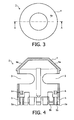
- Figure 3 shows a top view of cylindrical body 1.
- Figure 4 shows a cross-sectional view of cylindrical body 1 along the line A-A in figure 3 .
- FIG 5 shows a clamping element 10 which is adapted for co-action with the above described cylindrical body 1, and wherein the parts together form a seal.
- Clamping element 10 comprises a circular base 11 which is provided with a plurality of through-openings 12 for forming a filter in base 11.
- Three lips 13 are connected to base 11 over the periphery of base 11.
- protrusions 14 are connected to lips 13 for the purpose, in co-action with recesses 6 of cylindrical body 1, of holding clamping element 10 in cylindrical body 1 in a position leaving oesophageal tissue free (see also figure 9 ).
- Lips 13 are distributed over the periphery of the base such that they correspond with openings 3 distributed over the periphery of peripheral wall 2 of cylindrical body 1.
- Figure 6 shows a top view of clamping element 10.
- Figure 7 shows a front view of clamping element 10.
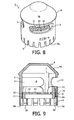
- Figure 8 shows a seal according to the invention comprising cylindrical body 1 and clamping element 10.
- Clamping element 10 is placed in cylindrical body 1 in a position leaving oesophageal tissue free.
- figure 9 shows a cross-section of cylindrical body 1, in which clamping element 10 is placed in a position leaving oesophageal tissue free.
- FIG 9 shows that protrusions 14 of clamping element 10 rest on edges 6a of recesses 6 in peripheral wall 2 of cylindrical body 1. The mutual alignment of protrusions 14 relative to recesses 6 in rotation direction is obtained with guide 7.
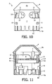
- Figure 10 shows cylindrical body 1 in which clamping element 10 is placed in a position clamping oesophageal tissue, this position being designated as clamping position.
- protrusions 14 of clamping element 10 rest on edges 3a of openings 3 in peripheral wall 2. If tissue of the oesophagus extends in receiving space 8 of cylindrical part 1, it is clamped between clamping element 10 and peripheral wall 2.
- Figure 11 shows a cross-section of cylindrical body 1 in which clamping element 10 is placed in a position clamping oesophageal tissue.
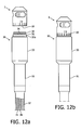
- Figure 12a shows a device 30 for placing a seal in the oesophagus of a slaughtered animal, which seal is formed by a cylindrical body 1 as shown in figure 1 and a clamping element 10 as shown in figure 5 , this clamping element 10 being placed inside cylindrical body 1.
- Device 30 comprises an elongate element formed as a tube 31. Connected to tube 31 at a first end thereof is a carrier 32 provided with an edge 32a for fixing cylindrical body 1 to carrier 32 via the resilient tongues 5 of cylindrical body 1, this position being shown in figure 12b .
- Clamping element 10 is here fixed with cylindrical body 1 in a position for placing the seal in the oesophagus.
- Device 30 is provided with a protective sleeve 33, the inner diameter of which has substantially the same diameter as the outer diameter of cylindrical body 1, wherein protective sleeve 33 can be placed over cylindrical body 1 as shown in figure 12c . In this position protective sleeve 33 extends beyond openings 3 of cylindrical body 1, i.e. as far as end wall 4.
- the seal formed by cylindrical body 1 and clamping element 10 can hereby be placed through an oesophagus up to a desired location in the oesophagus without substance, such as food or at least partially digested food, being able to enter the receiving space of cylindrical body 1.
- device 30 with cylindrical body 1 and clamping element 10 placed thereon is inserted into the oesophagus through the mouth of the animal.
- the underpressure is preferably such that fatty tissue on the outside of the oesophagus is also urged into receiving space 8, whereby an improved closure of the oesophagus is obtained since the volume of the fatty tissue situated in the receiving space of cylindrical body 1 provides for a form-locking coupling of clamping element 10 and cylindrical body 1 to the oesophagus.
- the underpressure is applied and oesophageal tissue extends into receiving space 8 of cylindrical body 1
- the oesophagus is already sealed and a pressure can be exerted on the seal, for instance by liquid present in the oesophagus.
- clamping element 10 is then urged to openings 3 of cylindrical body 1 by second urging means 34 extending in tube 31, wherein lips 13 of clamping element 10 are located substantially opposite openings 3.
- protrusions 14 of clamping element 10 rest on edges 3a of openings 3, as also shown in figure 11 .
- Clamping element 10 hereby camps the oesophageal tissue situated in receiving space 8 between lips 13 of clamping element 10 and peripheral wall 2. The underpressure applied in receiving space 8 can be removed.
- the closure of the oesophagus is secured by placing clamping element 10 into a clamping position in cylindrical body 1. If desired, the side of the clamped part of the oesophagus remote from the stomach of the slaughtered animal can be washed clean and/or sterilized.
- Carrier 32 must be uncoupled from the seal formed by cylindrical body 1 and clamping element 10 in order to enable withdrawal of device 30 from the oesophagus.
- protective sleeve 33 is moved in the direction of tube 31 so that edge 32 and the resilient tongues 5 extending around the edge are released (see figure 12f ).
- Carrier 32 is moved relative to device 30 in the direction of the seal via second urging means 34.
- Cylindrical body 1 is hereby uncoupled from carrier 32 as shown in figure 12g .
- Device 30 can be withdrawn and taken out of the oesophagus, this being shown in figure 12h .
- the closure in the oesophagus remains sufficiently strong even after the removal of device 30.
- the slaughtered animal can be further processed.
- Operating tool 40 comprises a housing 41, provided at a first short end 41a with a first opening 42 and at a second short end 41b with a second opening 43.
- a peripheral wall 49 is placed inside housing 41, whereby a space 50a is obtained between housing 41 and peripheral wall 49.
- a vacuum pump and/or a hose can be connected to operating tool 40 in order to respectively apply an underpressure in space 50a or allow a fluid to flow through the space for washing or sterilizing purposes.
- Space 50a is brought into open connection with a space 50b located between hose 37 and jacket 35 through openings 48 present in peripheral wall 49 close to the second short end 41b.
- An underpressure can hereby be applied in a seal coupled to carrier 32, and water or other suitable fluid can be transported in the direction of the carrier and through the seal.
- a first actuator 44 and a second actuator 45 are placed in the space enclosed by peripheral wall 49.
- First actuator 44 is coupled mechanically to jacket 35 via a coupling 46 and to second actuator 45 by means of a connection 47.
- Connection 47 is embodied such that, when first actuator 44 is displaced in the direction of the second short end 41b, first actuator 44 also urges second actuator 45 in the direction of the second short end 41b, but that first actuator 44 does not move relative to housing 41 when second actuator 45 is displaced in the direction of the second short end 41 b.
- first actuator 44 By displacing first actuator 44 a jacket 35 and an inner cable 36 can be displaced relative to a hose 37 lying round jacket 35 and inner cable 36.
- Jacket 35 and inner cable 36 extend here through opening 43 of housing 41.
- Electrical cables and control cables can be carried through opening 42 of housing 41 in order to provide electrical energy and signals for controlling first and second actuators 44, 45.
- a hose can also be coupled to housing 41 through opening 42, whereby water or other desired fluid can be guided through the space enclosed by the housing and discharged through through-openings 48 located in housing 41.
- the oesophagus and/or the seal can hereby be cleaned or sterilized at a desired position.
- a fluid is preferably carried in the direction of the seal when the seal is placed at a desired position in the oesophagus as shown in figure 12g .
- Jacket 35 is coupled mechanically to carrier 32 and the inner cable is coupled mechanically to second urging means 34, see also figure 12a .
- the seal is urged into protective sleeve 33 by displacing jacket 35 in the direction of the first short end 41a while operating first actuator 44. This takes place in the situation as shown in figure 12b , whereby the situation as shown in figure 12c is obtained. In this situation the seal can be introduced into the oesophagus.
- the rotating knife according to the above stated embodiment can also be applied individually, i.e. without a device for arranging the seal and with or without cleaning, washing or sterilizing system. There is therefore also the option of applying the seal, the method or the device for arranging the seal in the rectum of a slaughtered animal, this likewise being the case for the knife per se or in combination with a cleaning, washing or sterilizing system.
Landscapes
- Health & Medical Sciences (AREA)
- General Health & Medical Sciences (AREA)
- Otolaryngology (AREA)
- Life Sciences & Earth Sciences (AREA)
- Engineering & Computer Science (AREA)
- Food Science & Technology (AREA)
- Processing Of Meat And Fish (AREA)
- Medicinal Preparation (AREA)
- Surgical Instruments (AREA)
Claims (15)
- Dichtungselement für die Speiseröhre eines geschlachteten Tieres, beispielsweise einer Kuh, die umfasst:- einen zylinderischen Körper (1), der ausgelegt ist, in die Speiseröhre eingeführt zu werden und der eine zylindrische Außenwand (2) besitzt, die an einer Seite mit einer Abschlusswand (4) versehen ist, und- ein Klemmelement (10), das ausgelegt ist, relativ zum zylinderischen Körper (1) in eine Klemmposition zur Befestigung der Dichtung in der Speiseröhre verschoben zu werden und dabei die Speiseröhre abzudichten, indem Speiseröhrengewebe zwischen zumindest einem Teil des Klemmelements und dem zylinderischen Körper eingeklemmt wird,
dadurch gekennzeichnet, dass die Außenwand (2) einen Aufnahmeraum umschließt und mit zumindest einer Öffnung versehen ist, durch welche Speiseröhrengewebe in den Aufnahmeraum transportiert werden kann, und dass das Klemmelement in eine Klemmposition verschiebbar ist, in der Speiseröhrengewebe zwischen dem Klemmelement und dem zylinderischen Körper eingeklemmt wird. - Dichtungslement nach Anspruch 1, dadurch gekennzeichnet, dass der zylinderische Körper erste Befestigungsmittel zur Befestigung des Klemmelements in einer Transportstellung relativ zum zylinderischen Körper umfasst.
- Dichtungselement nach Anspruch 1 oder 2, dadurch gekennzeichnet, dass der zylinderische Körper zweite Befestigungsmittel zur Befestigung des Klemmelements in einer Klemmposition relativ zum zylinderischen Körper umfasst.
- Dichtungselement nach Anspruch 2 oder 3, dadurch gekennzeichnet, dass die ersten und zweiten Befestigungsmittel ausgelegt sind, das Klemmelement formschlüssig zu befestigen.
- Dichtungselement nach einem der vorhergehenden Ansprüche, dadurch gekennzeichnet, dass der zylinderische Körper Kupplungsmittel zur Verbindung des zylinderischen Körpers (1) mit einem Träger umfasst, um den zylinderischen Körper durch einen Teil der Speiseröhre mit einer gewünschten Stelle in der Speiseröhre zu positionieren.
- Dichtungselement nach einem der vorhergehenden Ansprüche, dadurch gekennzeichnet, dass das Klemmelement ringförmig und an einer Kante davon versehen ist, mit mindestens einem Vorsprung (5) zum Klemmen von Speiseröhrengewebe zwischen zumindest einem Teil des Vorsprungs und dem zylinderischen Körper.
- Dichtungselement nach einem der vorhergehenden Ansprüche, dadurch gekennzeichnet, dass der Außendurchmesser des zylinderischen Körpers zwischen 30 und 55 mm liegt.
- Dichtungselement nach einem der vorhergehenden Ansprüche, dadurch gekennzeichnet, dass der zylinderische Körper und/oder das Klemmelement im Wesentlichen aus einem Material gefertigt ist, das aus der Gruppe ausgewählt wurde, die besteht aus: einem Kunststoff, einem biologisch abbaubaren Material und einem essbaren Material.
- Vorrichtung (30) zur Anordnung und Befestigung eines Dichtungselementes in der Speiseröhre eines geschlachteten Tieres, beispielsweise einer Kuh, worin die Vorrichtung umfasst:- einen Träger (32), der an einem erste Ende eines länglichen Elements angeordnet ist, zum Positionieren einer Dichtung durch einen Teil der Speiseröhre und an einem gewünschten Ort in der Speiseröhre;- erste forcierende Mittel, die vom zweiten Ende des länglichen Elements gesteuert werden, um Speiseröhrengewebe durch eine Öffnung eines zylindrischen Teils der Dichtung in das Innere des zylindrischen Teils zu treiben; und- zweite forcierende Mittel (34), die vom zweiten Ende des länglichen Elements gesteuert werden, um ein Klemmelement der Dichtung in eine Klemmposition relativ zum zylindrischen Teil zu treiben, worin im Inneren des zylindrischen Teils vorhandenes Speiseröhrengewebe in der Klemmposition festgehalten wird.
- Vorrichtung nach Anspruch 9, dadurch gekennzeichnet, dass die ersten forcierenden Mittel Vakuummittel zum Schaffen eines Unterdrucks im Inneren eines in die Speiseröhre platzierten zylinderischen Körpers umfassen, wobei Speiseröhrengewebe durch in dem zylinderischen Körper angeordnete Öffnungen ins Körperinnere getrieben wird.
- Vorrichtung nach Anspruch 9 oder 10, dadurch gekennzeichnet, dass bei Betrieb die zweiten forcierenden Mittel (34) zwecks Bewegung des Klemmelements in axialer Richtung zumindest teilweise in das Innere des zylinderischen Körpers bewegt werden können.
- Verfahren zum Abdichten der Speiseröhre bei einem geschlachteten Tier, beispielsweise einer Kuh, durch Anordnen eines Dichtungselementes, wobei das Verfahren umfasst:- Platzieren eines zylindrischen Teils einer Dichtung, der mit einer zylindrischen Außenwand (2) und mit einer Abschlusswand (4) an einem Ende versehen ist, an einer gewünschten Stelle in der Speiseröhre des Tieres; und- Verschieben eines Klemmelements (10) der Dichtung relativ zum zylindrischen Teil in eine Klemmposition, wobei Speiseröhrengewebe zwischen dem Klemmelement und dem zylindrischen Teil fest eingespannt wird,
dadurch gekennzeichnet, dass das Speiseröhrengewebe durch mindestens eine in der Außenwand befindliche Öffnung in das Innere des zylindrischen Teils getrieben wird, und dass das so verschobene Gewebe zwischen dem in eine Klemmposition bewegten Klemmelement und dem zylindrischen Teil fest verschoben wird. - Verfahren nach Anspruch 12, dadurch gekennzeichnet, dass das Speiseröhrengewebe durch Anwendung eines Unterdrucks im Inneren des zylindrischen Teils in das Innere des zylindrischen Teils getrieben wird.
- Verfahren nach Anspruch 12 oder 13, dadurch gekennzeichnet, dass der zylindrische Teil und das Klemmelement durch das Maul des Tieres zu der gewünschten Stelle in der Speiseröhre eingeführt werden.
- Verfahren nach Anspruch 12, 13 oder 14, dadurch gekennzeichnet, dass das Klemmelement im Inneren des zylindrischen Teils bis in die Klemmposition bewegt wird.
Applications Claiming Priority (2)
| Application Number | Priority Date | Filing Date | Title |
|---|---|---|---|
| NL2003787A NL2003787C2 (nl) | 2009-11-11 | 2009-11-11 | Afsluiter, samenstellende delen van de afsluiter, inrichting en werkwijze voor het aanbrengen van een dergelijke afsluiter. |
| PCT/NL2010/050744 WO2011059318A1 (en) | 2009-11-11 | 2010-11-10 | Seal, constituent parts of the seal, device and method for arranging such a seal |
Publications (2)
| Publication Number | Publication Date |
|---|---|
| EP2498615A1 EP2498615A1 (de) | 2012-09-19 |
| EP2498615B1 true EP2498615B1 (de) | 2013-08-28 |
Family
ID=42212078
Family Applications (1)
| Application Number | Title | Priority Date | Filing Date |
|---|---|---|---|
| EP10782440.1A Active EP2498615B1 (de) | 2009-11-11 | 2010-11-10 | Dichtung, vorrichtung und verfahren zur anordnung einer derartigen dichtung |
Country Status (8)
| Country | Link |
|---|---|
| US (1) | US8771045B2 (de) |
| EP (1) | EP2498615B1 (de) |
| AR (1) | AR078974A1 (de) |
| AU (1) | AU2010318841B2 (de) |
| BR (1) | BR112012011148B1 (de) |
| NL (1) | NL2003787C2 (de) |
| NZ (1) | NZ599986A (de) |
| WO (1) | WO2011059318A1 (de) |
Families Citing this family (3)
| Publication number | Priority date | Publication date | Assignee | Title |
|---|---|---|---|---|
| NL2006676C2 (nl) * | 2011-04-28 | 2012-10-30 | Kuziba B V | Afsluiter, samenstellende delen van de afsluiter, inrichting en werkwijze voor het aanbrengen van een dergelijke afsluiter. |
| US10039913B2 (en) | 2015-07-30 | 2018-08-07 | Carefusion 303, Inc. | Tamper-resistant cap |
| CN110201293A (zh) * | 2019-07-03 | 2019-09-06 | 重庆金山科技(集团)有限公司 | 一种倒刺圈、胶囊组件、胶囊输送及固定装置 |
Family Cites Families (40)
| Publication number | Priority date | Publication date | Assignee | Title |
|---|---|---|---|---|
| US3407160A (en) | 1965-10-19 | 1968-10-22 | Baker Castor Oil Co | Rheological agents |
| US3864294A (en) | 1972-11-02 | 1975-02-04 | Chesebrough Ponds | Gelled coating compositions and method of making same |
| US4112979A (en) * | 1974-01-31 | 1978-09-12 | Naylor Brothers (Clayware) Limited | End cap for pipes |
| GB1518425A (en) * | 1976-02-19 | 1978-07-19 | Furmanite Int Ltd | Tube plug |
| US4407310A (en) | 1978-06-08 | 1983-10-04 | Kristy Wells, Inc. | Sculptured artificial nail |
| DE3017383C2 (de) * | 1980-05-07 | 1982-05-06 | Dietrich 7778 Markdorf Grünau | Kabelverschraubung für Schaltschränke |
| JPS61210020A (ja) | 1985-03-15 | 1986-09-18 | Shiseido Co Ltd | 美爪料 |
| GB8709608D0 (en) | 1987-04-23 | 1987-05-28 | Corrocoat Ltd | Forming glass flakes |
| JPH0780745B2 (ja) | 1987-05-07 | 1995-08-30 | 日本ペイント株式会社 | ネイルエナメル |
| GB9021252D0 (en) | 1990-09-29 | 1990-11-14 | Boots Co Plc | Nail lacquers |
| ZA917360B (en) | 1990-10-01 | 1992-06-24 | Oreal | Nail enamel containing oxidized polyethylene coated inorganic pigments |
| FR2698002B1 (fr) | 1992-11-13 | 1995-01-13 | Oreal | Composition cosmétique de maquillage contenant un fullerène ou un mélange de fullerènes comme agent pigmentant. |
| DE4318534C2 (de) * | 1993-06-03 | 1996-07-11 | United Carr Gmbh Trw | Haltedübel |
| NZ293519A (en) * | 1994-09-26 | 1996-11-26 | Commw Scient Ind Res Org | Rectum separating for use with slaughtered animal carcass: gripper located inside a closure bag |
| CA2195000C (en) * | 1995-05-11 | 2003-04-15 | Albert James Vick | Oesophagus sealing |
| DE19520312B4 (de) | 1995-06-02 | 2004-09-16 | Eckart-Werke Standard-Bronzepulver-Werke Carl Eckart Gmbh & Co. | Oxidierte farbige Aluminiumpigmente, Verfahren zu deren Herstellung sowie deren Verwendung |
| JP3273016B2 (ja) | 1998-04-21 | 2002-04-08 | 関西ペイント株式会社 | 印刷可能なベースコート用光硬化型塗料組成物 |
| EP1043967A1 (de) | 1998-11-05 | 2000-10-18 | L'oreal | Nagellack-zusammensetzungen enthaltend mikrosphäre |
| FR2785532B1 (fr) | 1998-11-06 | 2000-12-15 | Oreal | Procede de maquillage des matieres keratiniques |
| US6190249B1 (en) * | 2000-02-23 | 2001-02-20 | Ralph K. Karubian | Weasand clip |
| DE10024466A1 (de) | 2000-05-18 | 2001-11-22 | Merck Patent Gmbh | Pigmente mit Opalstruktur |
| DE10114446A1 (de) | 2001-03-23 | 2002-09-26 | Eckart Standard Bronzepulver | Eiseneffektpigmente |
| DE10238090A1 (de) | 2002-08-21 | 2004-03-04 | Eckart Gmbh & Co. Kg | Pigment und pigmentiertes Kosmetikum |
| AU2002358907A1 (en) | 2002-12-19 | 2004-07-14 | Glassflake Limited | Method and apparatus for forming glass flakes and fibres |
| DE10354763A1 (de) | 2003-11-21 | 2005-06-23 | Eckart Gmbh & Co. Kg | Effektpigmente mit Aluminium- oder Aluminiumlegierungskern, Verfahren zu deren Herstellung und Verwendung derselben |
| GB0330146D0 (en) | 2003-12-30 | 2004-02-04 | Glassflake Ltd | Formation of glass flakes |
| DE102004005366A1 (de) | 2004-02-03 | 2005-08-18 | Eckart Gmbh & Co.Kg | Kosmetisches Präparat enthaltend ein Metallpigment |
| FR2870452B1 (fr) | 2004-05-19 | 2008-10-03 | Oreal | Film de vernis a ongles a effet optique |
| EP1933804A2 (de) | 2005-10-03 | 2008-06-25 | L'Oréal | Nagel-makeup- oder pflege-methode |
| US20070190000A1 (en) | 2006-01-26 | 2007-08-16 | L'oreal | Matting cosmetic composition |
| DE102006016452A1 (de) | 2006-04-07 | 2007-10-11 | Bayer Materialscience Ag | Nitrocellulose basierte Bindemittel für wässrige Nagellacke |
| DE602007001237D1 (de) | 2007-04-05 | 2009-07-16 | Eckart Gmbh | Effektpigmente mit einem Substrat aus Glasplättchen |
| US9925396B2 (en) | 2008-01-30 | 2018-03-27 | L'oreal | Adhesive article containing colorant and/or active agent |
| EP2093260A1 (de) | 2008-02-20 | 2009-08-26 | Eckart GmbH | Effektpigmente basierend auf künstlich hergestellten Substraten mit enger Grössenverteilung |
| GB0803194D0 (en) | 2008-02-21 | 2008-04-02 | Microsphere Technology Ltd | Process for the manufacture of titania coated microspheres |
| DE102008021007A1 (de) | 2008-04-25 | 2009-11-12 | Byk-Chemie Gmbh | Dispersionen von Wachsen und anorganischen Nanopartikeln sowie deren Verwendung |
| DE102009037935A1 (de) | 2009-08-19 | 2011-02-24 | Eckart Gmbh | Hochglänzende Mehrschichtperlglanzpigmente mit silberner Interferenzfarbe und enger Größenverteilung und Verfahren zu deren Herstellung |
| DE102009037934A1 (de) | 2009-08-19 | 2011-02-24 | Eckart Gmbh | Hochglänzende Mehrschichtperlglanzpigmente mit farbiger Interferenzfarbe und enger Größenverteilung und Verfahren zu deren Herstellung |
| DE102009037933A1 (de) | 2009-08-19 | 2011-02-24 | Eckart Gmbh | Hochglänzende Mehrschichtperlglanzpigmente mit nichtsilberner Interferenzfarbe und enger Größenverteilung und Verfahren zu deren Herstellung |
| DE102009037932A1 (de) | 2009-08-19 | 2011-02-24 | Eckart Gmbh | Hochglänzende Mehrschichtperlglanzpigmente mit enger Größenverteilung und Verfahren zu deren Herstellung |
-
2009
- 2009-11-11 NL NL2003787A patent/NL2003787C2/nl not_active IP Right Cessation
-
2010
- 2010-11-10 AU AU2010318841A patent/AU2010318841B2/en active Active
- 2010-11-10 US US13/509,057 patent/US8771045B2/en active Active
- 2010-11-10 EP EP10782440.1A patent/EP2498615B1/de active Active
- 2010-11-10 NZ NZ599986A patent/NZ599986A/en unknown
- 2010-11-10 WO PCT/NL2010/050744 patent/WO2011059318A1/en not_active Ceased
- 2010-11-10 BR BR112012011148-5A patent/BR112012011148B1/pt active IP Right Grant
- 2010-11-11 AR ARP100104184A patent/AR078974A1/es active IP Right Grant
Also Published As
| Publication number | Publication date |
|---|---|
| AR078974A1 (es) | 2011-12-14 |
| BR112012011148B1 (pt) | 2019-06-11 |
| BR112012011148A8 (pt) | 2018-04-17 |
| AU2010318841A1 (en) | 2012-05-31 |
| EP2498615A1 (de) | 2012-09-19 |
| AU2010318841B2 (en) | 2015-01-22 |
| BR112012011148A2 (pt) | 2018-02-20 |
| NL2003787C2 (nl) | 2011-05-12 |
| US20130102235A1 (en) | 2013-04-25 |
| NZ599986A (en) | 2014-07-25 |
| WO2011059318A1 (en) | 2011-05-19 |
| US8771045B2 (en) | 2014-07-08 |
Similar Documents
| Publication | Publication Date | Title |
|---|---|---|
| US8771045B2 (en) | Seal, constituent parts of the seal, device and method for arranging such a seal | |
| CN104870045B (zh) | 用于将绳状元件插入患者体内的护套组件 | |
| MX2009013207A (es) | Un cateter y un metodo y un aparato para fabricar tal cateter. | |
| RU2601179C2 (ru) | Концевая защитная гильза | |
| RU2011122548A (ru) | Манжеты, магистрали, системы и способы приложения пониженного давления к участку подкожной ткани | |
| EP3818946A1 (de) | Vorrichtung zum einspritzen von medizinischem pulver in einen körper | |
| JPH09201330A (ja) | ドレナージチューブ組立体 | |
| CN109862922B (zh) | 医疗装置、特别是用于治疗瘘管的医疗装置 | |
| WO2012158021A1 (en) | Seal, constituent parts of the seal, device and method for arranging such a seal | |
| EP2811836A1 (de) | Rektumsschneidevorrichtung zum herausschneiden des rektums von schlachttieren | |
| CN101579248A (zh) | 套入式固定吻合环 | |
| EP2501978B1 (de) | Vorrichtung mit wenigstens einem Hohlelement zur Leitung eines Fluids und mit einem Verbindungselement | |
| EP3741318A1 (de) | Intrakavitäre interventionelle ultraschallsteuerungsvorrichtung | |
| EP2168501A1 (de) | Medizinische vorrichtung für biopsien | |
| AU2021250830B2 (en) | A bung driller with a bung holder | |
| EP3087951B1 (de) | Brust-implantat einführvorrichtung | |
| EP1587362B1 (de) | Verfahren zur identifizierung und überwachung von tieren mittels verwendung von elektronischen identifizierungsvorrichtungen (transponder) | |
| WO2023052382A1 (en) | A cutting device, a system including a cutting device and a method for cutting free a rectum end portion of an animal carcass | |
| CA2652664A1 (en) | Piercing tip | |
| EP1260141B1 (de) | Kloakenschneider | |
| EP0771148B1 (de) | Verschliessen der speiseröhre | |
| WO2018235151A1 (ja) | 医療用マニピュレータシステム | |
| CN217525385U (zh) | 一种用于防止血管蒂卡压的血管鞘管 | |
| CN201481479U (zh) | 一种套入式锁扣吻合环 | |
| PL147689B1 (en) | Apparatus for preventing hog lungs infection during post-slaughtering processing |
Legal Events
| Date | Code | Title | Description |
|---|---|---|---|
| PUAI | Public reference made under article 153(3) epc to a published international application that has entered the european phase |
Free format text: ORIGINAL CODE: 0009012 |
|
| 17P | Request for examination filed |
Effective date: 20120611 |
|
| AK | Designated contracting states |
Kind code of ref document: A1 Designated state(s): AL AT BE BG CH CY CZ DE DK EE ES FI FR GB GR HR HU IE IS IT LI LT LU LV MC MK MT NL NO PL PT RO RS SE SI SK SM TR |
|
| DAX | Request for extension of the european patent (deleted) | ||
| GRAP | Despatch of communication of intention to grant a patent |
Free format text: ORIGINAL CODE: EPIDOSNIGR1 |
|
| GRAS | Grant fee paid |
Free format text: ORIGINAL CODE: EPIDOSNIGR3 |
|
| GRAA | (expected) grant |
Free format text: ORIGINAL CODE: 0009210 |
|
| AK | Designated contracting states |
Kind code of ref document: B1 Designated state(s): AL AT BE BG CH CY CZ DE DK EE ES FI FR GB GR HR HU IE IS IT LI LT LU LV MC MK MT NL NO PL PT RO RS SE SI SK SM TR |
|
| REG | Reference to a national code |
Ref country code: GB Ref legal event code: FG4D |
|
| REG | Reference to a national code |
Ref country code: CH Ref legal event code: EP |
|
| REG | Reference to a national code |
Ref country code: AT Ref legal event code: REF Ref document number: 628779 Country of ref document: AT Kind code of ref document: T Effective date: 20130915 |
|
| REG | Reference to a national code |
Ref country code: IE Ref legal event code: FG4D |
|
| REG | Reference to a national code |
Ref country code: DE Ref legal event code: R096 Ref document number: 602010009886 Country of ref document: DE Effective date: 20131024 |
|
| REG | Reference to a national code |
Ref country code: NL Ref legal event code: T3 |
|
| REG | Reference to a national code |
Ref country code: AT Ref legal event code: MK05 Ref document number: 628779 Country of ref document: AT Kind code of ref document: T Effective date: 20130828 |
|
| REG | Reference to a national code |
Ref country code: LT Ref legal event code: MG4D |
|
| PG25 | Lapsed in a contracting state [announced via postgrant information from national office to epo] |
Ref country code: AT Free format text: LAPSE BECAUSE OF FAILURE TO SUBMIT A TRANSLATION OF THE DESCRIPTION OR TO PAY THE FEE WITHIN THE PRESCRIBED TIME-LIMIT Effective date: 20130828 Ref country code: NO Free format text: LAPSE BECAUSE OF FAILURE TO SUBMIT A TRANSLATION OF THE DESCRIPTION OR TO PAY THE FEE WITHIN THE PRESCRIBED TIME-LIMIT Effective date: 20131128 Ref country code: LT Free format text: LAPSE BECAUSE OF FAILURE TO SUBMIT A TRANSLATION OF THE DESCRIPTION OR TO PAY THE FEE WITHIN THE PRESCRIBED TIME-LIMIT Effective date: 20130828 Ref country code: IS Free format text: LAPSE BECAUSE OF FAILURE TO SUBMIT A TRANSLATION OF THE DESCRIPTION OR TO PAY THE FEE WITHIN THE PRESCRIBED TIME-LIMIT Effective date: 20131228 Ref country code: PT Free format text: LAPSE BECAUSE OF FAILURE TO SUBMIT A TRANSLATION OF THE DESCRIPTION OR TO PAY THE FEE WITHIN THE PRESCRIBED TIME-LIMIT Effective date: 20131230 Ref country code: SE Free format text: LAPSE BECAUSE OF FAILURE TO SUBMIT A TRANSLATION OF THE DESCRIPTION OR TO PAY THE FEE WITHIN THE PRESCRIBED TIME-LIMIT Effective date: 20130828 Ref country code: HR Free format text: LAPSE BECAUSE OF FAILURE TO SUBMIT A TRANSLATION OF THE DESCRIPTION OR TO PAY THE FEE WITHIN THE PRESCRIBED TIME-LIMIT Effective date: 20130828 Ref country code: CY Free format text: LAPSE BECAUSE OF FAILURE TO SUBMIT A TRANSLATION OF THE DESCRIPTION OR TO PAY THE FEE WITHIN THE PRESCRIBED TIME-LIMIT Effective date: 20130911 |
|
| PG25 | Lapsed in a contracting state [announced via postgrant information from national office to epo] |
Ref country code: FI Free format text: LAPSE BECAUSE OF FAILURE TO SUBMIT A TRANSLATION OF THE DESCRIPTION OR TO PAY THE FEE WITHIN THE PRESCRIBED TIME-LIMIT Effective date: 20130828 Ref country code: PL Free format text: LAPSE BECAUSE OF FAILURE TO SUBMIT A TRANSLATION OF THE DESCRIPTION OR TO PAY THE FEE WITHIN THE PRESCRIBED TIME-LIMIT Effective date: 20130828 Ref country code: BE Free format text: LAPSE BECAUSE OF FAILURE TO SUBMIT A TRANSLATION OF THE DESCRIPTION OR TO PAY THE FEE WITHIN THE PRESCRIBED TIME-LIMIT Effective date: 20130828 Ref country code: LV Free format text: LAPSE BECAUSE OF FAILURE TO SUBMIT A TRANSLATION OF THE DESCRIPTION OR TO PAY THE FEE WITHIN THE PRESCRIBED TIME-LIMIT Effective date: 20130828 Ref country code: SI Free format text: LAPSE BECAUSE OF FAILURE TO SUBMIT A TRANSLATION OF THE DESCRIPTION OR TO PAY THE FEE WITHIN THE PRESCRIBED TIME-LIMIT Effective date: 20130828 Ref country code: GR Free format text: LAPSE BECAUSE OF FAILURE TO SUBMIT A TRANSLATION OF THE DESCRIPTION OR TO PAY THE FEE WITHIN THE PRESCRIBED TIME-LIMIT Effective date: 20131129 |
|
| PG25 | Lapsed in a contracting state [announced via postgrant information from national office to epo] |
Ref country code: CY Free format text: LAPSE BECAUSE OF FAILURE TO SUBMIT A TRANSLATION OF THE DESCRIPTION OR TO PAY THE FEE WITHIN THE PRESCRIBED TIME-LIMIT Effective date: 20130828 |
|
| PG25 | Lapsed in a contracting state [announced via postgrant information from national office to epo] |
Ref country code: EE Free format text: LAPSE BECAUSE OF FAILURE TO SUBMIT A TRANSLATION OF THE DESCRIPTION OR TO PAY THE FEE WITHIN THE PRESCRIBED TIME-LIMIT Effective date: 20130828 Ref country code: RO Free format text: LAPSE BECAUSE OF FAILURE TO SUBMIT A TRANSLATION OF THE DESCRIPTION OR TO PAY THE FEE WITHIN THE PRESCRIBED TIME-LIMIT Effective date: 20130828 Ref country code: CZ Free format text: LAPSE BECAUSE OF FAILURE TO SUBMIT A TRANSLATION OF THE DESCRIPTION OR TO PAY THE FEE WITHIN THE PRESCRIBED TIME-LIMIT Effective date: 20130828 Ref country code: SK Free format text: LAPSE BECAUSE OF FAILURE TO SUBMIT A TRANSLATION OF THE DESCRIPTION OR TO PAY THE FEE WITHIN THE PRESCRIBED TIME-LIMIT Effective date: 20130828 Ref country code: DK Free format text: LAPSE BECAUSE OF FAILURE TO SUBMIT A TRANSLATION OF THE DESCRIPTION OR TO PAY THE FEE WITHIN THE PRESCRIBED TIME-LIMIT Effective date: 20130828 |
|
| PG25 | Lapsed in a contracting state [announced via postgrant information from national office to epo] |
Ref country code: ES Free format text: LAPSE BECAUSE OF FAILURE TO SUBMIT A TRANSLATION OF THE DESCRIPTION OR TO PAY THE FEE WITHIN THE PRESCRIBED TIME-LIMIT Effective date: 20130828 |
|
| REG | Reference to a national code |
Ref country code: DE Ref legal event code: R097 Ref document number: 602010009886 Country of ref document: DE |
|
| PLBE | No opposition filed within time limit |
Free format text: ORIGINAL CODE: 0009261 |
|
| STAA | Information on the status of an ep patent application or granted ep patent |
Free format text: STATUS: NO OPPOSITION FILED WITHIN TIME LIMIT |
|
| PG25 | Lapsed in a contracting state [announced via postgrant information from national office to epo] |
Ref country code: MC Free format text: LAPSE BECAUSE OF FAILURE TO SUBMIT A TRANSLATION OF THE DESCRIPTION OR TO PAY THE FEE WITHIN THE PRESCRIBED TIME-LIMIT Effective date: 20130828 |
|
| 26N | No opposition filed |
Effective date: 20140530 |
|
| REG | Reference to a national code |
Ref country code: DE Ref legal event code: R097 Ref document number: 602010009886 Country of ref document: DE Effective date: 20140530 |
|
| PG25 | Lapsed in a contracting state [announced via postgrant information from national office to epo] |
Ref country code: SM Free format text: LAPSE BECAUSE OF FAILURE TO SUBMIT A TRANSLATION OF THE DESCRIPTION OR TO PAY THE FEE WITHIN THE PRESCRIBED TIME-LIMIT Effective date: 20130828 |
|
| REG | Reference to a national code |
Ref country code: CH Ref legal event code: PL |
|
| PG25 | Lapsed in a contracting state [announced via postgrant information from national office to epo] |
Ref country code: MK Free format text: LAPSE BECAUSE OF FAILURE TO SUBMIT A TRANSLATION OF THE DESCRIPTION OR TO PAY THE FEE WITHIN THE PRESCRIBED TIME-LIMIT Effective date: 20130828 Ref country code: CH Free format text: LAPSE BECAUSE OF NON-PAYMENT OF DUE FEES Effective date: 20141130 Ref country code: HU Free format text: LAPSE BECAUSE OF FAILURE TO SUBMIT A TRANSLATION OF THE DESCRIPTION OR TO PAY THE FEE WITHIN THE PRESCRIBED TIME-LIMIT; INVALID AB INITIO Effective date: 20101110 Ref country code: LI Free format text: LAPSE BECAUSE OF NON-PAYMENT OF DUE FEES Effective date: 20141130 Ref country code: RS Free format text: LAPSE BECAUSE OF FAILURE TO SUBMIT A TRANSLATION OF THE DESCRIPTION OR TO PAY THE FEE WITHIN THE PRESCRIBED TIME-LIMIT Effective date: 20131128 Ref country code: LU Free format text: LAPSE BECAUSE OF NON-PAYMENT OF DUE FEES Effective date: 20131110 Ref country code: BG Free format text: LAPSE BECAUSE OF FAILURE TO SUBMIT A TRANSLATION OF THE DESCRIPTION OR TO PAY THE FEE WITHIN THE PRESCRIBED TIME-LIMIT Effective date: 20130828 |
|
| PG25 | Lapsed in a contracting state [announced via postgrant information from national office to epo] |
Ref country code: MT Free format text: LAPSE BECAUSE OF FAILURE TO SUBMIT A TRANSLATION OF THE DESCRIPTION OR TO PAY THE FEE WITHIN THE PRESCRIBED TIME-LIMIT Effective date: 20130828 |
|
| REG | Reference to a national code |
Ref country code: FR Ref legal event code: PLFP Year of fee payment: 6 |
|
| PG25 | Lapsed in a contracting state [announced via postgrant information from national office to epo] |
Ref country code: TR Free format text: LAPSE BECAUSE OF FAILURE TO SUBMIT A TRANSLATION OF THE DESCRIPTION OR TO PAY THE FEE WITHIN THE PRESCRIBED TIME-LIMIT Effective date: 20130828 |
|
| REG | Reference to a national code |
Ref country code: NL Ref legal event code: RC Free format text: DETAILS LICENCE OR PLEDGE: PANDRECHT, GEVESTIGD Name of requester: COOEPERATIEVE RABOBANK ENSCHEDE-HAAKSBERGEN U.A. Effective date: 20161107 |
|
| REG | Reference to a national code |
Ref country code: FR Ref legal event code: PLFP Year of fee payment: 7 |
|
| REG | Reference to a national code |
Ref country code: FR Ref legal event code: PLFP Year of fee payment: 8 |
|
| PG25 | Lapsed in a contracting state [announced via postgrant information from national office to epo] |
Ref country code: AL Free format text: LAPSE BECAUSE OF FAILURE TO SUBMIT A TRANSLATION OF THE DESCRIPTION OR TO PAY THE FEE WITHIN THE PRESCRIBED TIME-LIMIT Effective date: 20130828 |
|
| PGFP | Annual fee paid to national office [announced via postgrant information from national office to epo] |
Ref country code: NL Payment date: 20251126 Year of fee payment: 16 |
|
| PGFP | Annual fee paid to national office [announced via postgrant information from national office to epo] |
Ref country code: DE Payment date: 20251128 Year of fee payment: 16 |
|
| PGFP | Annual fee paid to national office [announced via postgrant information from national office to epo] |
Ref country code: GB Payment date: 20251127 Year of fee payment: 16 |
|
| PGFP | Annual fee paid to national office [announced via postgrant information from national office to epo] |
Ref country code: IT Payment date: 20251119 Year of fee payment: 16 |
|
| PGFP | Annual fee paid to national office [announced via postgrant information from national office to epo] |
Ref country code: FR Payment date: 20251125 Year of fee payment: 16 |
|
| PGFP | Annual fee paid to national office [announced via postgrant information from national office to epo] |
Ref country code: IE Payment date: 20251127 Year of fee payment: 16 |