EP2498353B1 - Appareil électrique à fixer par encliquetage sur un rail de support horizontal - Google Patents
Appareil électrique à fixer par encliquetage sur un rail de support horizontal Download PDFInfo
- Publication number
- EP2498353B1 EP2498353B1 EP12158859.4A EP12158859A EP2498353B1 EP 2498353 B1 EP2498353 B1 EP 2498353B1 EP 12158859 A EP12158859 A EP 12158859A EP 2498353 B1 EP2498353 B1 EP 2498353B1
- Authority
- EP
- European Patent Office
- Prior art keywords
- appliance
- carriage
- slider
- claw
- lateral
- Prior art date
- Legal status (The legal status is an assumption and is not a legal conclusion. Google has not performed a legal analysis and makes no representation as to the accuracy of the status listed.)
- Active
Links
- 210000000078 claw Anatomy 0.000 claims description 78
- 239000000463 material Substances 0.000 claims description 4
- 239000002991 molded plastic Substances 0.000 claims description 3
- 210000003323 beak Anatomy 0.000 description 9
- 244000221110 common millet Species 0.000 description 8
- BASFCYQUMIYNBI-UHFFFAOYSA-N platinum Chemical compound [Pt] BASFCYQUMIYNBI-UHFFFAOYSA-N 0.000 description 6
- 208000031968 Cadaver Diseases 0.000 description 5
- 240000008042 Zea mays Species 0.000 description 5
- 238000012550 audit Methods 0.000 description 5
- 239000004033 plastic Substances 0.000 description 5
- 229920003023 plastic Polymers 0.000 description 5
- 244000126211 Hericium coralloides Species 0.000 description 4
- 238000005452 bending Methods 0.000 description 4
- 238000000605 extraction Methods 0.000 description 4
- 239000002184 metal Substances 0.000 description 2
- 230000000284 resting effect Effects 0.000 description 2
- 229940082150 encore Drugs 0.000 description 1
- 238000005516 engineering process Methods 0.000 description 1
- 230000002349 favourable effect Effects 0.000 description 1
- 210000002445 nipple Anatomy 0.000 description 1
- 230000001681 protective effect Effects 0.000 description 1
- 230000002040 relaxant effect Effects 0.000 description 1
- 230000000717 retained effect Effects 0.000 description 1
- 125000006850 spacer group Chemical group 0.000 description 1
Images


Classifications
-
- H—ELECTRICITY
- H02—GENERATION; CONVERSION OR DISTRIBUTION OF ELECTRIC POWER
- H02B—BOARDS, SUBSTATIONS OR SWITCHING ARRANGEMENTS FOR THE SUPPLY OR DISTRIBUTION OF ELECTRIC POWER
- H02B1/00—Frameworks, boards, panels, desks, casings; Details of substations or switching arrangements
- H02B1/015—Boards, panels, desks; Parts thereof or accessories therefor
- H02B1/04—Mounting thereon of switches or of other devices in general, the switch or device having, or being without, casing
- H02B1/052—Mounting on rails
- H02B1/0523—Mounting on rails locked into position by a sliding member
Definitions
- the invention relates to electrical devices to snap onto a horizontal support rail having an upper wing and a lower wing.
- such electrical devices have on a rear face an upper spout and a lower spout facing each other and are configured to be fixed to the rail with the upper flange engaged between the upper spout and the body of the the apparatus and with the lower flange engaged between the lower spout and the body of the apparatus, the lower spout being elastically retractable to allow attachment of the apparatus on the rail snap.
- the erased position of the claw is particularly useful in countries, such as Germany, in which the practice is to feed the different devices attached side by side on the rail by a distribution comb of electrical energy arranged horizontally under devices with the comb teeth each engaged in a narrow slot in the underside of the apparatus to join a connection terminal internal to the device.
- Such a comb is generally rigid, so that to release one of the devices in the row, without disassembling the comb, it is necessary to be able to raise the device relative to the comb of the height of the teeth.
- the hole through which each tooth of the comb enters the apparatus is a narrow slot whose width corresponds to the width of the comb teeth, it is not possible to advance the apparatus to release it. lower wing of the rail, when the claw is in the service position.
- the lowered position of the claw makes it possible to raise the apparatus of the desired quantity without being impeded by the fixing rail.
- the invention aims to provide a similar device whose claw is reliable while being simple, convenient and economical.
- the invention proposes for this purpose an electrical device to be fixed by snapping on a horizontal support rail having an upper wing and a lower wing, which apparatus has on a rear face an upper beak and a lower beak facing one of the other, said apparatus being configured to be fixed to said rail with said upper flange engaged between the upper spout and the body of the apparatus and with said lower flange engaged between the lower spout and the body of the apparatus, said lower spout being resiliently retractable to allow attachment of the apparatus to the snap-in rail, said lower spout being part of a claw having a service position for securing the apparatus to the rail and an erased position for releasing the rail apparatus of said rail, wherein the claw is lowered relative to the service position; the claw comprising a one-piece carriage comprising a frame and a ratchet having in the absence of bias a rest position from which it can flex elastically, said carriage being mounted by said frame, sliding on the body of the apparatus enters a high position where the claw is
- the carriage that includes the claw of the device according to the invention comprises, in one piece, a frame by which the carriage is slidably mounted on the body of the device and a pawl for locking the claw in the service position and unlock it so that it can be lowered to the erased position.
- the frame for sliding mounting on the body of the apparatus and the pawl are part of the same part, the positioning of the pawl relative to the body of the device is particularly accurate, to the benefit of quality and the reliability of the cooperation between the body of the device and the truck.
- the claw of the apparatus according to the invention has an arrangement for its implementation in a simple, convenient and economical way.
- the apparatus comprises a separate spring of the carriage and the slide, disposed between said slide and said pawl of the carriage.
- the carriage and the slide can each play their role independently, to the benefit of the quality and reliability of operation.
- the spring is separate from the carriage and the slide, it can be in a different material.
- the carriage and the slider can be made of plastic while the spring is made of metal, to the benefit of the durability of its action (a plastic spring becomes brittle with time).
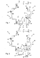
- the electrical apparatus 10 illustrated on the figure 1 has a generally parallelepipedal shape.
- main faces 11 and side faces extending from one to the other of the main faces 11, namely a rear face 12, a lower face 13, a front face 14 and an upper face 15.
- the rear face 12 has a notch 16 for mounting the device 1 on a standard support rail with an ⁇ profile such as the rail 20.
- the lower face 13 has access orifices (not shown) to a connection terminal 21.
- the terminal 21 receives a tooth 22 of a comb 23 for distributing electrical energy.
- the orifice of the lower face 13 through which the tooth 22 is introduced into the apparatus 10 is a narrow slot whose width (dimension in the front-rear direction) is slightly greater than the thickness of the tooth 22.
- the lower face 13 has, behind the orifice through which is introduced the tooth 22, another access port to the terminal 21, relatively extended in the front-rear direction, to accommodate the stripped end of an electric cable.
- the front face 14 has, in central position, about half of its length, a nose 24 having an operating lever 25. Under the nose 24 is an orifice for accessing the head of the screw of the terminal 21.
- the upper face 15 has an orifice (not shown) giving access to a connection terminal (not shown) similar to the terminal 21.
- this terminal receives the stripped end of an electrical cable (not shown) from the start to a terminal divisional circuit such as a lighting circuit or a circuit of sockets.
- the orifice of the upper face 15 through which the stripped end of the starting electrical cable is introduced into the apparatus 10 is relatively extended in the front-rear direction.
- the apparatus 10 is of the modular type, that is to say that in addition to its generally parallelepipedic shape, its width (distance between the two main faces 11) is a multiple of a normalized value, known as of "module", which is of the order of 18 mm.
- the apparatus 10 is a unipolar circuit breaker with a width of a module.
- the rail 20 has a central portion 26 in the form of a channel and a wing 27 and a wing 28 which each project from a respective end of the central portion 26, outwardly.
- the wings 27 and 28 are generally oriented in the same plane.
- the rail 20 is designed to be fixed horizontally on a wall, belonging for example to an enclosure such as an electrical box or an electrical cabinet.
- the wings 27 and 28 are designed to be oriented vertically, with the central portion 26 behind the wings 27 and 28 and resting on the support wall.
- the wing 27 is the upper wing and the wing 28 is the lower wing.
- the apparatus 10 For attachment of the apparatus 10 to the support rail 20, the apparatus 10 has two beaks 30 and 31.
- the spout 30 is formed by one end of a heel 32 whose other end protrudes from the upper face 15 of the apparatus 10.
- the heel 32 has a service position (illustrated position on the Figures 1 and 2 ) where it is immobilized relative to the body of the apparatus 10 with the spout 30 which protrudes from the upper edge 33 of the notch 16; and it is possible to put the heel 32, exerting a force directed upwards on the portion of the heel 32 which protrudes above the upper face 15, in an erased position where the spout 30 is retracted into the body of the apparatus 10.
- the spout 31 belongs to a claw 35.
- the claw 35 comprises a carriage 36 slidably mounted on the body of the apparatus 10, a slider 37 slidably mounted in the carriage 36 and a spring 39 ( figures 6 , 7 and 10 ) to urge the slider 37 to an extended position where one end of the slider 37, forming the spout 31, projects from the upper edge 34 of the sled 36.
- the slider 37 is retractable, against the spring 39, into the sled 36.
- the claw 35 has a service position, illustrated on the figure 1 , where the carriage 36 is immobilized relative to the body of the apparatus 10 with the upper edge 34 of the carriage 36 which forms the lower edge of the notch 16.
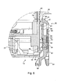
- the claw 35 also admits an erased position, illustrated on the figure 2 wherein the claw 35 is lowered relative to its operating position.
- the claw 35 comprises in the lower part a key 38 allowing, when the claw 35 is in the operating position, to unlock the carriage 36 vis-à-vis the body of the device 10. Once unlocked, the carriage 36 can slide screws to the body of the apparatus 10 to the erased position illustrated on the figure 2 which is a limit position of the carriage 36.
- the apparatus 10 is configured to be fixed to the rail 20 with the heel 32 and the claw 35 in the service position, the upper flange 27 being engaged between the spout 30 and the body of the apparatus 10; and the lower flange 28 engaged between the spout 31 and the body of the apparatus 10.
- the upper flange 27 is sandwiched between the spout 30 and the surface 40 of the body of the apparatus 10 which delimits the bottom of the notch 16, the edge of the upper flange 27 is opposite the edge upper 33 of the notch 16, the lower flange 28 is sandwiched between the spout 31 and the bottom surface 40, and the edge of the lower flange 28 is opposite the lower edge of the notch 16, formed here by the upper edge 34 of the carriage 36.
- Fixing the device 10 on the rail 20 is by snapping.
- the apparatus 10 is configured to be fixed to the support rail 20 by engagement of the upper flange 27 between the body of the apparatus 10 and the spout 30 while the apparatus 10 is inclined so that the spout 31 remote from the lower wing 28, then by tilting the apparatus 10 around the wing upper 27 to bring the spout 31 of the lower flange 28, the spout 31 retracting in contact with the lower flange 28 to allow the lower flange 28 to cross the spout 31 and the spout 31 unfolds for the lower wing 28 is retained between the body of the apparatus 10 and the spout 31.
- the apparatus 10 is adapted to be disposed with other modular electrical appliances on the support rail 20, to form a row of electrical appliances side by side.
- the comb 23 of horizontal distribution of the electrical energy is used to power the apparatus 10 and the other apparatus of the row.
- the comb 23 has a plurality of teeth such that the tooth 22 each engaged in an apparatus such as the apparatus 10.
- the device 10 can be removed from the row of devices without the need to disassemble the comb 23 of the row of devices.
- the gap between the nozzles 30 and 31 is such that the apparatus 10 can be sufficiently raised, relative to the comb 23, so that the tooth 22 is completely out of the apparatus 10 and that consequently the apparatus 10 is both released from the rail 20 and the comb 23, as shown on the figure 2 .
- the power supply of the devices of the row is carried out by a comb located above the apparatuses with each tooth of this comb engaged in a device by a relatively large opening in the forward direction rear part allowing both a comb tooth and the bare end of an electric cable to reach the connection terminal situated under the upper face 15.
- the electrical apparatus 10 can also be used in these countries, with a comb tooth which accesses the terminal located under the upper face 15 through the relatively wide orifice formed in the upper face 15, and with the starting electrical cable which access to the terminal 21 through the relatively wide orifice formed in the lower face 13.
- the orifice in the upper face 15 is sized to allow access to both a comb tooth and the bare end of an electrical cable, this orifice is much wider in the forward direction. back only the thickness of a comb tooth.
- the spout 30 is not retractable in the body of the apparatus 10 but is fixed, being for example in one piece with the body of the apparatus 10.
- the surface 40 of the body of the apparatus 10 which forms the bottom of the notch 16 is extended by a surface 43 which extends from the surface 40 to the bottom face 13.
- each groove 45 and the surface 43 there is a rib 46 whose slice 47 is set back with respect to the main face 11.
- the gap between the slice 47 and the main face 11 allows the lateral faces of the carriage 36 to be slightly recessed with respect to the main face 11. This allows the carriage 36 to slide even when the apparatus 10 is part of a row of devices with each main face 11 of the apparatus 10 which is against a main face of a neighboring apparatus.
- a tab 48 protrudes from the surface 43.
- the tab 48 is elongate in the horizontal direction.
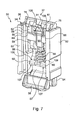
- the carriage 36 is made of plastic molded in one piece. It comprises a chassis 50 and a pawl 51.
- the chassis 50 has two lateral flanges 52, an upper cross member 53 extending from one side to the other side flanges 52 at their end upper and a lower cross member 54 extending from one to the other side flanges 52 at their lower end.
- each flange 52 forms a rib 55 along a groove 56.
- the rib 55 is configured to be received in the groove 45 of the body of the apparatus 10 while the groove 56 is configured to receive the rib 46 of the body of the apparatus 10.
- the grooves and ribs 45, 46, 55 and 56 provide sliding guidance of the carriage 36 with respect to the body of the apparatus 10.
- the upper end of the groove 45 forms an end stop for the carriage 36, and more specifically for the upper edge of the rib 55.
- Pawl 51 takes root on top rail 53, from which it extends downward.
- the distal end of the pawl 51 (opposite end to that by which the pawl 51 takes root on the upper cross member 53) forms the lower end of the key 38.
- the pawl 51 successively comprises a plate 57, two cheeks 58 and two hinges 59.
- the lower end of the plate 57 is connected to the upper end of the key 38.
- the lower end of each flange 58 is connected to the upper end of the plate 57.
- the lower end of each hinge 59 is connected. at the upper end of a respective cheek 58.
- the upper end of each hinge 59 is connected to the upper cross member 53.
- the hinges 59 are formed by plastic portions of smaller section than the other areas of the pawl 51.
- the deflection of the pawl 51 allows the key 38 to move backward until it meets the bottom rail 54, which forms a limit stop.
- the deflection of the pawl 51 is elastic, that is to say that when it stops exerting a force, the pawl 51 returns to its rest position shown in the drawings.
- the pawl 51 has a lug 60 projecting forwardly.
- each lug 60 is engaged with the tab 48.
- the claw 35 is locked in the service position.
- the slider 37 comprises a sill 61 whose one end forms the spout 31. On the side of the sill 61 opposite the end forming the spout 31 project two lateral arms 62 and a central rod 63.
- the upper cross member 53 has passages 68 and 69 respectively for the central rod 63 and for the lateral arms 62.
- the lateral arms 62 each fit between a lateral flange 52 and a cheek 58 while the central rod 63 is housed between the cheeks 58.
- the spring 39 is respectively engaged with the lower end of the central rod 63 and with the upper end of the plate 57.
- the spring 39 is able to deform to accompany the bending and elastic return movements of the pawl 51; while it is essentially the frame 50 (and not the pawl 51) which guides the slider 37 in the carriage 36.
- the upper cross member 53 comprises a plate 64 located at the rear and two brackets 65 each having a first branch 66 rooted on the plate 64 and a second branch 67 extending between the first branch 66 and the side flange 52 closest .
- the two brackets 65 are arranged in mirror image of one another.
- each of the brackets 65 is below the upper edge 34 of the carriage 36 (upper edge of the frame 50).
- Each of the hinges 59 is rooted on the upper cross member 53 by the front face of the first branch 66 of a respective bracket 65.
- each lateral arm 62 has at its distal end (end opposite the sill 61) a notch 70 projecting forwards.
- the rear face of each arm 62 is flat and likewise for the front face of the portion of each arm 62 located between the notch 70 and the sill 61.
- Each notch 70 has a horizontal face 71 looking towards the sill 61, that is to say upwards, and an inclined face 72 forming a ramp between the horizontal face 71 and the lower edge of the arm 62.
- each lateral arm 62 has a rib 75 protruding forwardly.
- Each rib 75 has a horizontal face 76 facing the horizontal face 71 of the notch 70. In other words, the horizontal face 76 looks down.
- the front face of the sill 61 has, from the upper edge, a vertical face 77 which connects to a face 78 inclined forwardly and downwardly.
- the upper face of the rib 75 belongs to the inclined face 78.
- the sill 61 comprises three ribs projecting rearwards, respectively a central rib 79 and two lateral ribs 80.
- the central rib 79 protrudes more than the lateral ribs 80.
- the rear face of the sill 61 has, from the upper edge, a face 81 inclined downwardly and rearwardly.
- the upper face of the ribs 79 and 80 belongs to the inclined face 81.
- the central rod 63 of the slider 37 comprises a fork 85 comprising two arms 86, a cross-member 87 and an end finger 88.
- each arm 86 projects downward from the sill 61.
- the lower end of each arm 86 is connected to a respective end of the cross member 87.
- End finger 88 protrudes downward from the center of crossbar 87.
- the central rod 63 comprises, in addition to the fork 85, a flexible tab 90 which projects upwardly from the cross-member 87.
- the flexible tab 90 takes root on the front face of the cross member 87 and is more generally in front of the fork 85. More specifically, apart from the lower end of the flexible tab 90 which is connected to the cross member 87, the flexible tab 90 is in front of the space framed by the arms 86, the cross 87 and the sill 61. The flexible tab 90 can thus flex in this space, without its flexion being impeded by the sill 61 and the arms 86.
- the flexible tab 90 has at its distal end (end opposite the cross 87) a notch 91 protruding forward.
- the notch 91 has a horizontal face 92 and an inclined face 93 forming a ramp between the horizontal face 92 and the upper edge of the flexible tab 90.
- the flexible tab 90 has a rib 94 less prominent than the notch 91.
- the rib 94 has a face 95 inclined downwardly and rearwardly and a face 96 inclined upwardly and rearwardly.
- the upper edge of the face 95 is connected to the lower edge of the face 96.
- the face 96 is less inclined than the face 95.
- the notch 91 and the rib 94 are configured to cooperate with the projection 49 protruding in the middle of the tab 48.
- the plate 64 has in front of each bracket 65 a groove 100 for accommodating a respective lateral rib 80 of the sill 61.
- the plate 64 has between the grooves 100 a notch 101 to accommodate the central rib 79 of the sill 61.
- the second branch 67 has a horizontal face 102 ( figure 11 ) who looks down.
- each face 102 is connected to a face (not visible in the drawings) inclined upwards and forwards.
- the thickness (dimension front-back) of the second branch 67 of the bracket 65 increases from top to bottom, to be maximum at the face 102.
- the pawl 51 has between the two cheeks 58, at the rear, a wall 105.
- the lugs 60 have a portion projecting above the upper edge of the plate 64.
- the wall 105 and the protruding portions of the lugs 60 serve to retain the spring 39.
- the wall 105 and the protruding portions of the lugs 60 are replaced by a stud projecting upwards from the upper edge of the plate 57, with the lower end of the spring 39 which surrounds this nipple.
- the claw 35 is assembled by arranging the spring 39 between the cheeks 58 with the lower end of the spring 39 against the upper edge of the plate 57.
- the slide 37 is then engaged in the upper rail 53 with the rod central 63 which enters through the end finger 88 in the space 68 and with each side arm 62 which enters through its notch 70 in a respective space 69.
- each notch 70 meets the inclined face (not visible in the drawings) of the second branch 67 of the corresponding bracket 65, so that each lateral arm 62 flexes to what the notch 70 has crossed the second branch 67. Each arm 62 then relaxes and the horizontal face 71 of the notch 70 comes opposite the horizontal face 102 of the corresponding second branch 67.
- the spring 39 relaxes and returns the slide 37 in the position where the spout 31 is deployed.
- Each of the brackets 65 has, in overhang towards the other bracket 65, at the front, a rib 106.
- the flexible tab 90 is housed between the ribs 106.
- Each arm 86 has its front edge facing the rear face of a respective rib 106.
- the rear face of the lower wing 28 is in contact with the front face of the sill 61, mainly by the inclined face 78, with the exercise on the spout 31 forming the upper end of the slider 37, a force directed towards the rear.
- the ribs 75 allow to give the inclined face 78 a certain extension.
- the downward and backward inclination of the face 81 causes the slider 37 to be biased downward so that the slider 37 retracts into the carriage 36 as the spring 39 compresses.
- the spring 39 expands and raises the slider 37 so that the spout 31 is returned to the deployed position.
- the lateral ribs 80 and especially the central rib 79 provide a certain extension to the face 81 favorable to good cooperation with the lower wing 28.
- the relatively long lateral arms 62 of the slider 37 contribute to the quality of the sliding guide between the frame 50 and the slider 37, the surface of each arm 62 located furthest to the right, while the leftmost sliding against the facing surface of the side flange 52 corresponding.
- the assembly of the claw 35 and the body of the apparatus 10 is effected by engaging, on each side, the rib 55 of the carriage 36 in the groove 45 of the body of the apparatus 10 and the rib 46 of this body in the groove 56 of the carriage 36 by the bottom of the body of the apparatus 10, then raising the claw 35 relative to the body of the apparatus 10.
- the notch 91 of the flexible tab 90 of the slide 37 meets the lug 49 which protrudes in the middle of the lug 48.
- the tab 90 bends backwards and, when the lug 49 is crossed, the lug 90 relaxes by returning to its rest position shown in the drawings.
- the rib 94 in turn meets the lug 49.
- the flexible lug flexes backwards again and when the lug 49 is crossed by the rib 94, the lug 90 relaxes and resumes his resting position. Then, the chins 60 meet the tab 48.
- the pawl 51 bends backwards and when the chins 60 have crossed the tab 48, the pawl 51 relaxes and returns to its position. rest illustrated in the drawings while the carriage 36 reaches the end of stroke upwards, by coming into contact with the upper edge of the rib 55 with the upper end of the groove 45.
- the claw 35 is then in the illustrated service position on the figures 1 and 6 .
- each of the chins 60 the lower face 107 is a horizontal face facing downwards.
- Each lug 60 has an upper face 109 inclined upwardly and rearwardly.
- the upper face 108 of the tab 48 is a horizontal face which looks upwards.
- the tab 48 also has an inclined face ramping between the upper face 108 and its lower face.
- the lug 49 has an upper face 111 which is a horizontal face looking upwards.
- the upper face 111 of the lug 49 and the upper face 108 of the lug 48 are flush with each other.
- the lug 49 has an inclined face 112 which forms a ramp between the upper face 111 and its lower face.
- the lower face of the lug 49 is flush with the underside of the lug 48.
- the orientation of the upper face 109 of the chins 60 and the orientation of the inclined face 110 of the tab 48 are such that the pawl 51 flexes when the claw 35 is elevated relative to the body of the apparatus 10.
- the lug 49 is housed between the lugs 60.
- the bending of the pawl 51 allows the chins 60 to be behind the tab 48 and thus to be released from this tab.
- the claw 35 can then be lowered.
- the rib 94 of the flexible tab 90 meets the lug 49.
- the tab 90 bends backwards, so that the rib 94 can cross the lug 49.
- the horizontal lower face 92 of the notch 91 meets the horizontal upper face 111 of the lug 49.
- the faces 92 and 111 being horizontal, the tab 90 does not flex and the claw 35 can not lower further.
- the rib 94 allows the user, who feels resistance when the rib 94 passes the lug 49, to be notified of the proximity of the end of the race down the claw 35.
- the rib 94 also keeps the claw 35 in the erased position, since to allow the claw 35 to rise relative to the body of the apparatus 10, it is necessary to exert a certain effort so that the rib 94 can cross the ergot 49.
- the lower cross member 54 is just behind the key 38. As explained above, the lower cross member 54 provides a limit stop for the key 38, limiting the bending towards the rear of the ratchet 51.
- the lower cross member 54 is formed by a plate disposed at the rear, under the lateral flanges 52.
- the lower crossbar also has a front plate located in front of the key 38 and connected, by arms located on either side of the key 38, to a plate similar to the lower rail 54.
- Bib is formed a central window to access the key 38.
- the edge of the lower wing 28 is opposite the upper edge 34 of the carriage 36.
- the force exerted on the upper edge 34 can be very important.
- the locking in the service position provided by the pawl 51 is particularly safe and can withstand extremely high forces, without the chins 60 escape the tab 48; in particular thanks to the arrangement of the flanges 58, hinges 59 and the upper cross member 53.
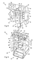
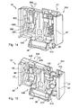
- the apparatus 10 ' is similar to the apparatus 10, except that its width (distance between the two main faces 11') is twice the width of the apparatus 10, c that is, the apparatus 10 'has a width of two modules.
- the surface 43 'of the body of the apparatus 10 comprises two tabs 48A and 48B each similar to the tab 48 of the apparatus 10.
- a lug 49A protrudes rearwardly.
- a lug 49B protrudes rearwardly.
- the lugs 49A and 49B are similar to the lug 49.
- the carriage 36 ' just like the carriage 36, is made of plastic molded in one piece.
- the frame 50 'of the carriage 36' is twice as wide as the frame 50 of the carriage 36.
- the frame 50 ' has two lateral flanges 52' similar to the flange 52 of the frame 50.
- each of the flanges 52 ' forms a rib 55' running along a groove 56 ', with the rib 55' which is configured to be received in the groove 45 'of the body of the apparatus 10' while the groove 56 'is configured to receive the rib 46' of the body of the apparatus 10 '.
- the frame 50' Halfway between the lateral flanges 52 ', the frame 50' comprises a spar 120.
- portion 50A of the frame 50 located between the spar 120 and the lateral flange 52 ' which is seen to the left on the figure 12 (right on the Figures 14 and 15 ) is arranged as the portion of the frame 50 located between the lateral flanges 52.
- the portion 50B of the frame 50 located between the spar 120 and the lateral flange 52 'which is seen to the right on the figure 12 (left on the Figures 14 and 15 ) is arranged as the frame 50 except that this portion does not receive slider.
- the portion 50A of the frame 50 ' comprises between the spar 120 and the side flange 52' corresponding, an upper cross member 53A similar to the cross 53 of the frame 50.
- the carriage 36 ' comprises, in the portion 50A of the frame 50', a pawl 51A similar to the pawl 51 of the carriage 36, except for the plate 57 and the key 38, as explained below.
- the portion of the carriage 36 'formed by the portion 50A of the frame 50' and the pawl 51A receives a slider 37 'and a spring 39' identical to the slider 37 and the spring 39 of the claw 35.
- the portion 50B of the frame 50 ' comprises between the spar 120 and the side flange 52' corresponding, an upper cross member 53B extending from one to the other of the spar 120 and the side flange 52 'corresponding.
- the carriage 36 ' has in the portion 50B of the frame 50', a pawl 51B similar to the pawl 51 of the carriage 36, with the exception of the plate 57 and the key 38 while the pawl 51B further comprises a flexible tab 90B similar to the flexible tab 90 of the slider 37.
- the flexible tab 90B rooted on the front face of a wall 105B of the pawl 51B disposed between the two flaps 58B of the pawl 51B.
- the upper cross member 53B is configured to leave behind the flexible tab 90B a gap 121 allowing the flexible tab 90B to flex backward like the flexible tab 90 of the slider 37.
- the flexible tab 90B is disposed in the portion 50B of the frame 50 'at the same location as the flexible tab of the slider 37' in the portion 50A of the frame 50 ', when the slider 37' is in the extended position ( see it figure 14 ).
- the key 38 ' is common to the pawls 51A and 51B: the key 38' is centered on the spar 120 and is connected, on one side, to the plate 57A of the pawl 51A and, on the second side, to the plate 57B of the ratchet 51A.
- the lower cross member 54 'of the frame 50' comprises a central plate 122 projecting downwards from the lower end of the spar 120 and extending on either side of the spar 120 towards the respective lateral flanges 52 'for a certain distance .
- the plate 122 is connected to the corresponding lateral flange 52 'by a bracket 123.
- the plate 122 is disposed opposite the key 38 '.
- the plate 122 serves as an end stop for the key 38 '.
- the claw 35 ' is used as the claw 35, the pawl of the pawl 51A and the flexible tab of the slider 37' cooperating with the 48A lug and 49A lug while the pawl 51B pawls and the flexible tab 90B 51B pawl cooperate with the tab 48B and the lug 49B.
- the locking in the service position provided by the pawls 51A and 51B is particularly safe and can withstand extremely high forces when tightening the terminals of the apparatus 10 '; in particular thanks to the presence of two pawls 51A and 51B.
- the portions located on either side of the central spar are identical and each receive a slider similar to the slider 37.
- the portion of the claw such as 35 located between the spar such as 120 and one of the side flanges 52 ' is a simple spacer (there is no ratchet such as the pawl 51B).
- each of the pawls 51A and 51B has its own control key.
- the frame such as 50 or 50 'of the claw such as 35 or 35' does not include a bottom rail such as 54 or 54 '.
- the carriage such as 36 or 36 'is not molded plastic, but in another material, for example a folded metal strip, as the claw described in the German patent application DE 44 39 672 .
- the apparatus such as 10 or 10 'is not a single-pole circuit breaker, but a phase-neutral circuit breaker or a three-phase circuit breaker or other modular device that a circuit breaker, for example a differential switch or a device other than a protective device, for example a remote control switch.
Landscapes
- Engineering & Computer Science (AREA)
- Power Engineering (AREA)
- Connector Housings Or Holding Contact Members (AREA)
- Drawers Of Furniture (AREA)
- Carriages For Children, Sleds, And Other Hand-Operated Vehicles (AREA)
- Seats For Vehicles (AREA)
Priority Applications (1)
| Application Number | Priority Date | Filing Date | Title |
|---|---|---|---|
| PL12158859T PL2498353T3 (pl) | 2011-03-11 | 2012-03-09 | Urządzenie elektryczne do mocowania za pomocą mechanizmu zapadkowego na poziomej szynie montażowej |
Applications Claiming Priority (1)
| Application Number | Priority Date | Filing Date | Title |
|---|---|---|---|
| FR1152021A FR2972575B1 (fr) | 2011-03-11 | 2011-03-11 | Appareil electrique a fixer par encliquetage sur un rail de support horizontal |
Publications (2)
| Publication Number | Publication Date |
|---|---|
| EP2498353A1 EP2498353A1 (fr) | 2012-09-12 |
| EP2498353B1 true EP2498353B1 (fr) | 2015-02-18 |
Family
ID=45787139
Family Applications (1)
| Application Number | Title | Priority Date | Filing Date |
|---|---|---|---|
| EP12158859.4A Active EP2498353B1 (fr) | 2011-03-11 | 2012-03-09 | Appareil électrique à fixer par encliquetage sur un rail de support horizontal |
Country Status (4)
| Country | Link |
|---|---|
| EP (1) | EP2498353B1 (enExample) |
| FR (1) | FR2972575B1 (enExample) |
| IN (1) | IN2012DE00660A (enExample) |
| PL (1) | PL2498353T3 (enExample) |
Families Citing this family (4)
| Publication number | Priority date | Publication date | Assignee | Title |
|---|---|---|---|---|
| FR3023424B1 (fr) * | 2014-07-03 | 2016-07-22 | Abb France | Montage d’un systeme de demarrage sur une pluralite de rails de fixation |
| CN106461898B (zh) | 2015-05-08 | 2019-12-24 | 华为技术有限公司 | 一种光纤终端盒 |
| DE202016100467U1 (de) | 2016-01-30 | 2016-05-02 | Hora-Werk Gmbh | Rastvorrichtung für eine elektrische Baugruppe und Baugruppe mit einer Rastvorrichtung |
| CN118073976B (zh) * | 2024-03-06 | 2024-10-11 | 威海双城电气有限公司 | 一种高低压配电柜及方法 |
Family Cites Families (7)
| Publication number | Priority date | Publication date | Assignee | Title |
|---|---|---|---|---|
| FR2652205B1 (fr) | 1989-09-19 | 1992-05-29 | Legrand Sa | Dispositif de fixation rapide pour appareil electrique, et appareillage electrique correspondant. |
| DE4107075A1 (de) * | 1990-03-15 | 1991-09-19 | Abb Patent Gmbh | Schnappbefestigung fuer ein elektrisches installationsgeraet auf einer hutprofiltragschiene |
| DE4439672C2 (de) | 1994-11-07 | 2003-11-20 | Abb Patent Gmbh | Vorrichtung zur lösbaren Schnellbefestigung eines elektrischen Reiheneinbaugerätes, insbesondere eines Leitungsschutzschalters |
| EP1058360B1 (fr) * | 1999-05-31 | 2001-08-29 | Hager Electro S.A. | Système de fixation à grande course d'un appareil électrique modulaire standard à un rail |
| DE10220821B3 (de) * | 2002-05-10 | 2004-02-26 | Geyer Ag | Schnellbefestigungseinrichtung für Reiheneinbaugeräte |
| DE102004019173A1 (de) * | 2004-04-16 | 2005-11-03 | Abb Patent Gmbh | Schnellbefestigung für Installationsgeräte mit Anbauteilen |
| CN101128098B (zh) * | 2006-08-17 | 2010-05-12 | 浙江正泰电器股份有限公司 | 模数化电器的安装固定装置 |
-
2011
- 2011-03-11 FR FR1152021A patent/FR2972575B1/fr not_active Expired - Fee Related
-
2012
- 2012-03-07 IN IN660DE2012 patent/IN2012DE00660A/en unknown
- 2012-03-09 EP EP12158859.4A patent/EP2498353B1/fr active Active
- 2012-03-09 PL PL12158859T patent/PL2498353T3/pl unknown
Also Published As
| Publication number | Publication date |
|---|---|
| FR2972575B1 (fr) | 2013-04-26 |
| FR2972575A1 (fr) | 2012-09-14 |
| IN2012DE00660A (enExample) | 2015-08-21 |
| EP2498353A1 (fr) | 2012-09-12 |
| PL2498353T3 (pl) | 2015-07-31 |
Similar Documents
| Publication | Publication Date | Title |
|---|---|---|
| EP2498353B1 (fr) | Appareil électrique à fixer par encliquetage sur un rail de support horizontal | |
| EP2808964B1 (fr) | Système pour fournir un support horizontal à un objet tel qu'un chemin de câbles et rail pour un tel système | |
| WO2017153492A1 (fr) | Tiroir destiné à être monté dans une armoire électrique | |
| EP1922224A1 (fr) | Siege de securite destine a installer un bebe ou un tres jeune enfant sur un siege de vehicule | |
| FR3013159A1 (fr) | Support pour appareillage electrique de faible epaisseur | |
| EP2369699B1 (fr) | Coffret ou tableau de distribution électrique comportant un rail de montage d'appareillages électriques amovible | |
| EP2369698B1 (fr) | Support de rail de montage d'appareillages électriques dans un coffret électrique | |
| EP2369700B1 (fr) | Coffret ou tableau de distribution électrique, équipé de supports de rail à pivot glissant | |
| EP2456021A1 (fr) | Prise électrique comportant des montants latéraux mobiles en translation | |
| EP2618352A1 (fr) | Appareil électrique au format modulaire | |
| EP3041022B1 (fr) | Appareil modulaire à pion de liaison rétractable et ensemble électrique auto-protegé comprenant un tel appareil modulaire assemblé à un disjoncteur | |
| EP3041021B1 (fr) | Appareil modulaire à sécurite renforcée et ensemble électrique auto-protégé comprenant un tel appareil modulaire assemblé à un disjoncteur | |
| FR2652205A1 (fr) | Dispositif de fixation rapide pour appareil electrique, et appareillage electrique correspondant. | |
| EP0418336B1 (fr) | Dispositif pour supporter les organes mecaniques et electriques de commande d'un grille-pain et grille-pain comportant un tel dispositif | |
| EP1463166B1 (fr) | Dispositif de verrouillage bistable pour appareil électrique interrupteur | |
| EP2535990B1 (fr) | Appareil électrique à fixer par encliquetage sur un rail de support horizontal | |
| EP1610416B1 (fr) | Appareil électrique adapté à coopérer avec un peigne de répartition horizontale | |
| EP2320532B1 (fr) | Dispositif de montage d'un montant de châssis sur le fond d'un coffret électrique et coffret électrique comprenant un tel dispositif | |
| EP2784885A1 (fr) | Elément amovible pour un appareillage modulaire électrique muni d une poignée pivotante | |
| EP2341589B1 (fr) | Dispositif de montage d'un montant de châssis sur le fond d'un coffret électrique et coffret électrique comprenant un tel dispositif | |
| EP1439621B1 (fr) | Appareillage du type modulaire à monter sur des barres de différentes épaisseurs | |
| FR3097680A1 (fr) | Appareil modulaire électrique muni d’un élément de blocage | |
| EP2273636A1 (fr) | Accessoire de prolongement d'un tronçon de goulotte | |
| FR3060217A1 (fr) | Dispositif de verrouillage de moyens d’alimentation electrique en position de connexion sur un appareil modulaire | |
| CH694308A5 (fr) | Sous-ensemble d'habillage pour un appareillage électrique à prise et interrupteur combinés. |
Legal Events
| Date | Code | Title | Description |
|---|---|---|---|
| PUAI | Public reference made under article 153(3) epc to a published international application that has entered the european phase |
Free format text: ORIGINAL CODE: 0009012 |
|
| AK | Designated contracting states |
Kind code of ref document: A1 Designated state(s): AL AT BE BG CH CY CZ DE DK EE ES FI FR GB GR HR HU IE IS IT LI LT LU LV MC MK MT NL NO PL PT RO RS SE SI SK SM TR |
|
| AX | Request for extension of the european patent |
Extension state: BA ME |
|
| 17P | Request for examination filed |
Effective date: 20121227 |
|
| GRAP | Despatch of communication of intention to grant a patent |
Free format text: ORIGINAL CODE: EPIDOSNIGR1 |
|
| INTG | Intention to grant announced |
Effective date: 20140903 |
|
| GRAS | Grant fee paid |
Free format text: ORIGINAL CODE: EPIDOSNIGR3 |
|
| GRAA | (expected) grant |
Free format text: ORIGINAL CODE: 0009210 |
|
| AK | Designated contracting states |
Kind code of ref document: B1 Designated state(s): AL AT BE BG CH CY CZ DE DK EE ES FI FR GB GR HR HU IE IS IT LI LT LU LV MC MK MT NL NO PL PT RO RS SE SI SK SM TR |
|
| REG | Reference to a national code |
Ref country code: GB Ref legal event code: FG4D Free format text: NOT ENGLISH |
|
| REG | Reference to a national code |
Ref country code: CH Ref legal event code: EP |
|
| REG | Reference to a national code |
Ref country code: AT Ref legal event code: REF Ref document number: 710991 Country of ref document: AT Kind code of ref document: T Effective date: 20150315 |
|
| REG | Reference to a national code |
Ref country code: IE Ref legal event code: FG4D Free format text: LANGUAGE OF EP DOCUMENT: FRENCH |
|
| REG | Reference to a national code |
Ref country code: DE Ref legal event code: R096 Ref document number: 602012005259 Country of ref document: DE Effective date: 20150402 |
|
| REG | Reference to a national code |
Ref country code: NL Ref legal event code: VDEP Effective date: 20150218 |
|
| REG | Reference to a national code |
Ref country code: AT Ref legal event code: MK05 Ref document number: 710991 Country of ref document: AT Kind code of ref document: T Effective date: 20150218 |
|
| REG | Reference to a national code |
Ref country code: LT Ref legal event code: MG4D |
|
| PG25 | Lapsed in a contracting state [announced via postgrant information from national office to epo] |
Ref country code: NO Free format text: LAPSE BECAUSE OF FAILURE TO SUBMIT A TRANSLATION OF THE DESCRIPTION OR TO PAY THE FEE WITHIN THE PRESCRIBED TIME-LIMIT Effective date: 20150518 Ref country code: HR Free format text: LAPSE BECAUSE OF FAILURE TO SUBMIT A TRANSLATION OF THE DESCRIPTION OR TO PAY THE FEE WITHIN THE PRESCRIBED TIME-LIMIT Effective date: 20150218 Ref country code: FI Free format text: LAPSE BECAUSE OF FAILURE TO SUBMIT A TRANSLATION OF THE DESCRIPTION OR TO PAY THE FEE WITHIN THE PRESCRIBED TIME-LIMIT Effective date: 20150218 Ref country code: SE Free format text: LAPSE BECAUSE OF FAILURE TO SUBMIT A TRANSLATION OF THE DESCRIPTION OR TO PAY THE FEE WITHIN THE PRESCRIBED TIME-LIMIT Effective date: 20150218 Ref country code: ES Free format text: LAPSE BECAUSE OF FAILURE TO SUBMIT A TRANSLATION OF THE DESCRIPTION OR TO PAY THE FEE WITHIN THE PRESCRIBED TIME-LIMIT Effective date: 20150218 Ref country code: LT Free format text: LAPSE BECAUSE OF FAILURE TO SUBMIT A TRANSLATION OF THE DESCRIPTION OR TO PAY THE FEE WITHIN THE PRESCRIBED TIME-LIMIT Effective date: 20150218 |
|
| REG | Reference to a national code |
Ref country code: PL Ref legal event code: T3 |
|
| PG25 | Lapsed in a contracting state [announced via postgrant information from national office to epo] |
Ref country code: IS Free format text: LAPSE BECAUSE OF FAILURE TO SUBMIT A TRANSLATION OF THE DESCRIPTION OR TO PAY THE FEE WITHIN THE PRESCRIBED TIME-LIMIT Effective date: 20150618 Ref country code: RS Free format text: LAPSE BECAUSE OF FAILURE TO SUBMIT A TRANSLATION OF THE DESCRIPTION OR TO PAY THE FEE WITHIN THE PRESCRIBED TIME-LIMIT Effective date: 20150218 Ref country code: NL Free format text: LAPSE BECAUSE OF FAILURE TO SUBMIT A TRANSLATION OF THE DESCRIPTION OR TO PAY THE FEE WITHIN THE PRESCRIBED TIME-LIMIT Effective date: 20150218 Ref country code: GR Free format text: LAPSE BECAUSE OF FAILURE TO SUBMIT A TRANSLATION OF THE DESCRIPTION OR TO PAY THE FEE WITHIN THE PRESCRIBED TIME-LIMIT Effective date: 20150519 Ref country code: AT Free format text: LAPSE BECAUSE OF FAILURE TO SUBMIT A TRANSLATION OF THE DESCRIPTION OR TO PAY THE FEE WITHIN THE PRESCRIBED TIME-LIMIT Effective date: 20150218 Ref country code: LV Free format text: LAPSE BECAUSE OF FAILURE TO SUBMIT A TRANSLATION OF THE DESCRIPTION OR TO PAY THE FEE WITHIN THE PRESCRIBED TIME-LIMIT Effective date: 20150218 |
|
| PG25 | Lapsed in a contracting state [announced via postgrant information from national office to epo] |
Ref country code: SK Free format text: LAPSE BECAUSE OF FAILURE TO SUBMIT A TRANSLATION OF THE DESCRIPTION OR TO PAY THE FEE WITHIN THE PRESCRIBED TIME-LIMIT Effective date: 20150218 Ref country code: CZ Free format text: LAPSE BECAUSE OF FAILURE TO SUBMIT A TRANSLATION OF THE DESCRIPTION OR TO PAY THE FEE WITHIN THE PRESCRIBED TIME-LIMIT Effective date: 20150218 Ref country code: EE Free format text: LAPSE BECAUSE OF FAILURE TO SUBMIT A TRANSLATION OF THE DESCRIPTION OR TO PAY THE FEE WITHIN THE PRESCRIBED TIME-LIMIT Effective date: 20150218 Ref country code: DK Free format text: LAPSE BECAUSE OF FAILURE TO SUBMIT A TRANSLATION OF THE DESCRIPTION OR TO PAY THE FEE WITHIN THE PRESCRIBED TIME-LIMIT Effective date: 20150218 Ref country code: RO Free format text: LAPSE BECAUSE OF FAILURE TO SUBMIT A TRANSLATION OF THE DESCRIPTION OR TO PAY THE FEE WITHIN THE PRESCRIBED TIME-LIMIT Effective date: 20150218 |
|
| REG | Reference to a national code |
Ref country code: CH Ref legal event code: PL |
|
| REG | Reference to a national code |
Ref country code: DE Ref legal event code: R097 Ref document number: 602012005259 Country of ref document: DE |
|
| PG25 | Lapsed in a contracting state [announced via postgrant information from national office to epo] |
Ref country code: MC Free format text: LAPSE BECAUSE OF FAILURE TO SUBMIT A TRANSLATION OF THE DESCRIPTION OR TO PAY THE FEE WITHIN THE PRESCRIBED TIME-LIMIT Effective date: 20150218 |
|
| PLBE | No opposition filed within time limit |
Free format text: ORIGINAL CODE: 0009261 |
|
| STAA | Information on the status of an ep patent application or granted ep patent |
Free format text: STATUS: NO OPPOSITION FILED WITHIN TIME LIMIT |
|
| PG25 | Lapsed in a contracting state [announced via postgrant information from national office to epo] |
Ref country code: IT Free format text: LAPSE BECAUSE OF FAILURE TO SUBMIT A TRANSLATION OF THE DESCRIPTION OR TO PAY THE FEE WITHIN THE PRESCRIBED TIME-LIMIT Effective date: 20150218 |
|
| REG | Reference to a national code |
Ref country code: IE Ref legal event code: MM4A |
|
| 26N | No opposition filed |
Effective date: 20151119 |
|
| PG25 | Lapsed in a contracting state [announced via postgrant information from national office to epo] |
Ref country code: IE Free format text: LAPSE BECAUSE OF NON-PAYMENT OF DUE FEES Effective date: 20150309 Ref country code: LI Free format text: LAPSE BECAUSE OF NON-PAYMENT OF DUE FEES Effective date: 20150331 Ref country code: CH Free format text: LAPSE BECAUSE OF NON-PAYMENT OF DUE FEES Effective date: 20150331 |
|
| PG25 | Lapsed in a contracting state [announced via postgrant information from national office to epo] |
Ref country code: SI Free format text: LAPSE BECAUSE OF FAILURE TO SUBMIT A TRANSLATION OF THE DESCRIPTION OR TO PAY THE FEE WITHIN THE PRESCRIBED TIME-LIMIT Effective date: 20150218 |
|
| REG | Reference to a national code |
Ref country code: FR Ref legal event code: PLFP Year of fee payment: 5 |
|
| GBPC | Gb: european patent ceased through non-payment of renewal fee |
Effective date: 20160309 |
|
| PG25 | Lapsed in a contracting state [announced via postgrant information from national office to epo] |
Ref country code: MT Free format text: LAPSE BECAUSE OF FAILURE TO SUBMIT A TRANSLATION OF THE DESCRIPTION OR TO PAY THE FEE WITHIN THE PRESCRIBED TIME-LIMIT Effective date: 20150218 |
|
| PG25 | Lapsed in a contracting state [announced via postgrant information from national office to epo] |
Ref country code: GB Free format text: LAPSE BECAUSE OF NON-PAYMENT OF DUE FEES Effective date: 20160309 |
|
| REG | Reference to a national code |
Ref country code: FR Ref legal event code: PLFP Year of fee payment: 6 |
|
| PG25 | Lapsed in a contracting state [announced via postgrant information from national office to epo] |
Ref country code: HU Free format text: LAPSE BECAUSE OF FAILURE TO SUBMIT A TRANSLATION OF THE DESCRIPTION OR TO PAY THE FEE WITHIN THE PRESCRIBED TIME-LIMIT; INVALID AB INITIO Effective date: 20120309 Ref country code: SM Free format text: LAPSE BECAUSE OF FAILURE TO SUBMIT A TRANSLATION OF THE DESCRIPTION OR TO PAY THE FEE WITHIN THE PRESCRIBED TIME-LIMIT Effective date: 20150218 Ref country code: BG Free format text: LAPSE BECAUSE OF FAILURE TO SUBMIT A TRANSLATION OF THE DESCRIPTION OR TO PAY THE FEE WITHIN THE PRESCRIBED TIME-LIMIT Effective date: 20150218 |
|
| PG25 | Lapsed in a contracting state [announced via postgrant information from national office to epo] |
Ref country code: CY Free format text: LAPSE BECAUSE OF FAILURE TO SUBMIT A TRANSLATION OF THE DESCRIPTION OR TO PAY THE FEE WITHIN THE PRESCRIBED TIME-LIMIT Effective date: 20150218 |
|
| PG25 | Lapsed in a contracting state [announced via postgrant information from national office to epo] |
Ref country code: PT Free format text: LAPSE BECAUSE OF FAILURE TO SUBMIT A TRANSLATION OF THE DESCRIPTION OR TO PAY THE FEE WITHIN THE PRESCRIBED TIME-LIMIT Effective date: 20150618 Ref country code: BE Free format text: LAPSE BECAUSE OF NON-PAYMENT OF DUE FEES Effective date: 20150331 |
|
| PG25 | Lapsed in a contracting state [announced via postgrant information from national office to epo] |
Ref country code: TR Free format text: LAPSE BECAUSE OF FAILURE TO SUBMIT A TRANSLATION OF THE DESCRIPTION OR TO PAY THE FEE WITHIN THE PRESCRIBED TIME-LIMIT Effective date: 20150218 |
|
| PG25 | Lapsed in a contracting state [announced via postgrant information from national office to epo] |
Ref country code: LU Free format text: LAPSE BECAUSE OF NON-PAYMENT OF DUE FEES Effective date: 20150309 |
|
| REG | Reference to a national code |
Ref country code: FR Ref legal event code: PLFP Year of fee payment: 7 |
|
| PG25 | Lapsed in a contracting state [announced via postgrant information from national office to epo] |
Ref country code: MK Free format text: LAPSE BECAUSE OF FAILURE TO SUBMIT A TRANSLATION OF THE DESCRIPTION OR TO PAY THE FEE WITHIN THE PRESCRIBED TIME-LIMIT Effective date: 20150218 |
|
| PG25 | Lapsed in a contracting state [announced via postgrant information from national office to epo] |
Ref country code: AL Free format text: LAPSE BECAUSE OF FAILURE TO SUBMIT A TRANSLATION OF THE DESCRIPTION OR TO PAY THE FEE WITHIN THE PRESCRIBED TIME-LIMIT Effective date: 20150218 |
|
| P01 | Opt-out of the competence of the unified patent court (upc) registered |
Effective date: 20230515 |
|
| PGFP | Annual fee paid to national office [announced via postgrant information from national office to epo] |
Ref country code: DE Payment date: 20250218 Year of fee payment: 14 |
|
| PGFP | Annual fee paid to national office [announced via postgrant information from national office to epo] |
Ref country code: FR Payment date: 20250218 Year of fee payment: 14 Ref country code: PL Payment date: 20250225 Year of fee payment: 14 |