EP2498339B1 - Anordnung mit einer Klemme und mindestens eine Klemmschraube - Google Patents
Anordnung mit einer Klemme und mindestens eine Klemmschraube Download PDFInfo
- Publication number
- EP2498339B1 EP2498339B1 EP11305268.2A EP11305268A EP2498339B1 EP 2498339 B1 EP2498339 B1 EP 2498339B1 EP 11305268 A EP11305268 A EP 11305268A EP 2498339 B1 EP2498339 B1 EP 2498339B1
- Authority
- EP
- European Patent Office
- Prior art keywords
- screw
- contact part
- clamp
- clamping screw
- tool
- Prior art date
- Legal status (The legal status is an assumption and is not a legal conclusion. Google has not performed a legal analysis and makes no representation as to the accuracy of the status listed.)
- Not-in-force
Links
- 239000004020 conductor Substances 0.000 claims description 19
- 238000010008 shearing Methods 0.000 abstract 1
- 229910000838 Al alloy Inorganic materials 0.000 description 3
- 229910052751 metal Inorganic materials 0.000 description 3
- 239000002184 metal Substances 0.000 description 3
- 238000010276 construction Methods 0.000 description 2
- 230000037431 insertion Effects 0.000 description 2
- 238000003780 insertion Methods 0.000 description 2
- 229910001369 Brass Inorganic materials 0.000 description 1
- RYGMFSIKBFXOCR-UHFFFAOYSA-N Copper Chemical compound [Cu] RYGMFSIKBFXOCR-UHFFFAOYSA-N 0.000 description 1
- 229910000831 Steel Inorganic materials 0.000 description 1
- 229910045601 alloy Inorganic materials 0.000 description 1
- 239000000956 alloy Substances 0.000 description 1
- 229910052782 aluminium Inorganic materials 0.000 description 1
- XAGFODPZIPBFFR-UHFFFAOYSA-N aluminium Chemical compound [Al] XAGFODPZIPBFFR-UHFFFAOYSA-N 0.000 description 1
- 239000010951 brass Substances 0.000 description 1
- 229910052802 copper Inorganic materials 0.000 description 1
- 239000010949 copper Substances 0.000 description 1
- 230000001771 impaired effect Effects 0.000 description 1
- 230000002093 peripheral effect Effects 0.000 description 1
- 239000004033 plastic Substances 0.000 description 1
- 239000010959 steel Substances 0.000 description 1
Images

Classifications
-
- H—ELECTRICITY
- H01—ELECTRIC ELEMENTS
- H01R—ELECTRICALLY-CONDUCTIVE CONNECTIONS; STRUCTURAL ASSOCIATIONS OF A PLURALITY OF MUTUALLY-INSULATED ELECTRICAL CONNECTING ELEMENTS; COUPLING DEVICES; CURRENT COLLECTORS
- H01R11/00—Individual connecting elements providing two or more spaced connecting locations for conductive members which are, or may be, thereby interconnected, e.g. end pieces for wires or cables supported by the wire or cable and having means for facilitating electrical connection to some other wire, terminal, or conductive member, blocks of binding posts
- H01R11/03—Individual connecting elements providing two or more spaced connecting locations for conductive members which are, or may be, thereby interconnected, e.g. end pieces for wires or cables supported by the wire or cable and having means for facilitating electrical connection to some other wire, terminal, or conductive member, blocks of binding posts characterised by the relationship between the connecting locations
- H01R11/09—Individual connecting elements providing two or more spaced connecting locations for conductive members which are, or may be, thereby interconnected, e.g. end pieces for wires or cables supported by the wire or cable and having means for facilitating electrical connection to some other wire, terminal, or conductive member, blocks of binding posts characterised by the relationship between the connecting locations the connecting locations being identical
-
- F—MECHANICAL ENGINEERING; LIGHTING; HEATING; WEAPONS; BLASTING
- F16—ENGINEERING ELEMENTS AND UNITS; GENERAL MEASURES FOR PRODUCING AND MAINTAINING EFFECTIVE FUNCTIONING OF MACHINES OR INSTALLATIONS; THERMAL INSULATION IN GENERAL
- F16B—DEVICES FOR FASTENING OR SECURING CONSTRUCTIONAL ELEMENTS OR MACHINE PARTS TOGETHER, e.g. NAILS, BOLTS, CIRCLIPS, CLAMPS, CLIPS OR WEDGES; JOINTS OR JOINTING
- F16B31/00—Screwed connections specially modified in view of tensile load; Break-bolts
- F16B31/02—Screwed connections specially modified in view of tensile load; Break-bolts for indicating the attainment of a particular tensile load or limiting tensile load
- F16B31/021—Screwed connections specially modified in view of tensile load; Break-bolts for indicating the attainment of a particular tensile load or limiting tensile load by means of a frangible part
-
- H—ELECTRICITY
- H01—ELECTRIC ELEMENTS
- H01R—ELECTRICALLY-CONDUCTIVE CONNECTIONS; STRUCTURAL ASSOCIATIONS OF A PLURALITY OF MUTUALLY-INSULATED ELECTRICAL CONNECTING ELEMENTS; COUPLING DEVICES; CURRENT COLLECTORS
- H01R4/00—Electrically-conductive connections between two or more conductive members in direct contact, i.e. touching one another; Means for effecting or maintaining such contact; Electrically-conductive connections having two or more spaced connecting locations for conductors and using contact members penetrating insulation
- H01R4/28—Clamped connections, spring connections
- H01R4/30—Clamped connections, spring connections utilising a screw or nut clamping member
- H01R4/36—Conductive members located under tip of screw
-
- F—MECHANICAL ENGINEERING; LIGHTING; HEATING; WEAPONS; BLASTING
- F16—ENGINEERING ELEMENTS AND UNITS; GENERAL MEASURES FOR PRODUCING AND MAINTAINING EFFECTIVE FUNCTIONING OF MACHINES OR INSTALLATIONS; THERMAL INSULATION IN GENERAL
- F16B—DEVICES FOR FASTENING OR SECURING CONSTRUCTIONAL ELEMENTS OR MACHINE PARTS TOGETHER, e.g. NAILS, BOLTS, CIRCLIPS, CLAMPS, CLIPS OR WEDGES; JOINTS OR JOINTING
- F16B35/00—Screw-bolts; Stay-bolts; Screw-threaded studs; Screws; Set screws
- F16B35/005—Set screws; Locking means therefor
Definitions
- the invention relates to an arrangement with a designed as a piece of pipe clamp made of metal and at least one clamping screw for fixing an electrical conductor in the clamp which has in its wall at least one threaded through hole for receiving the clamping screw, in its construction at least one An element for limiting the force, which is exerted on the same by means of a clamping screw acting on the rotation about its axis causing tool, wherein the clamping screw has a tubular, provided with an external thread and screwed into the through hole of the terminal contact part at its an axial end has a contact surface for abutment with an electrical conductor located in the clamp, EP 0 750 723 B1 ).
- Such, also referred to as “tear-off screw” or “shear screw” clamping screw - hereinafter referred to as “screw” - is used, for example, in power engineering for connecting the electrical conductors of two power cables.
- screw screw
- a fixed connection between the conductors of two cables and a tubular metal clamp is required, in which the conductors are inserted.
- Such a clamp is advantageously made of an aluminum alloy.
- the fixed connection could be ensured by using a so-called torque wrench, which then "rotates” when tightening the screw when a sufficient tight fit thereof is reached.
- torque wrench is often not available on a construction site. The screw is therefore usually tightened with another tool, for example with a simple wrench.
- the screw can be equipped as a shear screw with at least one predetermined breaking point, which is arranged in its axial course as a circumferential groove.
- the upper part of the screw is sheared off when the strength of its predetermined breaking point is reached or exceeded.
- the missing screw head is an indication that the screw is sufficiently tightened.
- the screw sticks out after the but not entirely out of the clamp. Therefore, an insulating member to be mounted thereover is either mechanically damaged or impaired in its insulating properties.
- the predetermined breaking point interrupts the thread of the screw, so that its load capacity is weakened. This makes the more pronounced noticeable, the Patderetti predetermined breaking points are present in a screw.
- a universal use of such screws for conductors of different diameters is because he r only possible with restrictions. In addition, it is often unavoidable that parts of the sheared screw interfere with the clamp.
- the screw mentioned at the beginning EP 0 750 723 B1 has in its course a plurality of designed as circumferential grooves predetermined breaking points, which are arranged parallel to each other and at an axial distance in threaded portion of the screw.
- the screw is also equipped with a central blind hole with a polygonal cross-section, which is close to the nearest to the screw tip predetermined breaking point.
- a rotary body consisting of a polygonal cross-section pin for insertion into the blind hole and a circumferentially surrounding hood to which the pin is attached and which has a hexagonal nut for applying a tool on the outside.
- the invention has for its object to the above-described screw g e sta lte n st, that it is without limiting its carrying capacity for determining located in a terminal ladders of any dimensions suitable.
- This screw is the contact part, which is the actual screw for fixing a conductor in a clamp.
- the actuating member is connected in the mounting position by the pin-like holding part with the contact part. Both parts thus form a unit in the assembly position.
- the screw thus formed is continuously rotated in the threaded hole of a clamp by means of a tool engaging the operating member until the contact surface of the contact member bears against a conductor of any diameter in the clamp and is pressed against it with a predetermined force. Once the desired tight fit of the contact part or the screw is reached, the holding part is sheared off.
- the actuating part can then be rotated on the contact part. It is moved in one direction towards the clamp.
- the contact part is finally torn off by the operating part, as soon as the Ibe rests on the clamp and is further rotated by means of the tool.
- the pin-like holding part is a threaded screw with a head and a threaded shank, between which there is a circumferential restriction to the ore ing the predetermined breaking point.
- the threaded screw is arranged in the mounting position with its head in a recess in the wall of the actuating part and is screwed with its threaded shaft in a threaded hole in the wall of the contact part.
- the contact part of the screw consists of a sufficiently strong, preferably electrically conductive, metal, plastic or brass alloy or aluminum alloy. Since s operating part of the screw can be made of steel, for example.
- the pin-like holding part to be inserted in the screw in the radial direction may have any shape as long as it allows the connection of the contact part and the operating part to a unit in the assembly position.
- the word "threaded bolt” is used in the following description instead of the word "holding part”.
- two or more threaded screws offset from each other in the circumferential direction of the screw may be used.
- Fig. 1 is a example of a tinned aluminum alloy existing, as Rohr Swissausgerendingt terminal 1 shown. It has two threaded holes, in each of which an externally threaded screw 2 is arranged. In the terminal 1 protrude from two different sides herelektwitz conductors 3 and 4 of two electrical cables 5 and 6, which are in particular energy cables. They are fixed in the mounting position by the screws 2 in the terminal 1 and thereby electrically connected mite incca.
- the electrical conductors 3 and 4 are designed in a preferred embodiment as Herdrähtige conductor. They are preferably made of aluminum or copper.
- the conductors 3 and 4 can also be constructed of segments in which individual wires are zusa mme ng e summarizes.
- the screw 2 consists of three parts to be screwed together, a contact part 7, an operating part 8 and a threaded screw 9.
- the contact part 7 is designed as a cylindrical hollow body with an external thread 10. At its end facing away from the contact surface 11, the contact part 7 has in its wall at least one threaded hole 12 for receiving the threaded screw 9. In the region of the threaded hole 12 is the wall of the contact part 7 preferably radially outwardly n projecting slightly thicker executed.
- the external thread 10 ends before this area.
- the executed as a piece of pipe actuator 8 has a réellege thread 13 and in its wall a through hole 14 for receiving the threaded screw 9.
- the portion thereof in which the through hole 14 is disposed may be radially expanded and threaded with respect to the internal thread portion 13 as shown in the drawings.
- the operating part 8 can according to Fig. 5 have a peripheral surface configured as a polygon, in particular as a se ck, for engaging a tool suitable for rotating the screw 2.
- the central opening of the actuating part 8 can also have a polygonal, preferably hexagonal, cross-section for insertion of a tool of the invention, at least in the upper area.
- the threaded screw 9 has accordingly Fig. 3 a preferably conical head 15 and a threaded shaft 16. Between head 15 and threaded shaft 16 is a circumferential constriction 17, which constitutes a predetermined breaking point for the threaded screw 9.
- the screw 2 is in the mounting state a us Fig. 4 out.
- the actuating part 8 is screwed onto the contact part 7. Both parts are connected by the threaded bolt 9 with one another, which is a screwed into the threaded hole 12 of the contact part 7 and is located with its head 15 in the through hole 14 of the operating part 8.
- the constriction 17 and there with the predetermined breaking point of the threaded screw 9 is in the gap between he n contact part 7 and operating part 8.
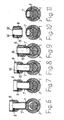
- the finished screw 2 is corresponding to the Fig. 6 to 11 for example, as follows for fixing an electrical conductor 3 in a terminal 1 handled:
- the wall thickness of the contact part 7 is to be sized depending on the magnitude of the force to be applied by the tool. The final position of the fixing part of the contact part 7 and the screw 2 goes out Fig. 11 out.
Landscapes
- Engineering & Computer Science (AREA)
- General Engineering & Computer Science (AREA)
- Mechanical Engineering (AREA)
- Connections By Means Of Piercing Elements, Nuts, Or Screws (AREA)
Priority Applications (6)
| Application Number | Priority Date | Filing Date | Title |
|---|---|---|---|
| PL11305268T PL2498339T3 (pl) | 2011-03-11 | 2011-03-11 | Układ z zaciskiem i co najmniej jedną śrubą zaciskową |
| EP11305268.2A EP2498339B1 (de) | 2011-03-11 | 2011-03-11 | Anordnung mit einer Klemme und mindestens eine Klemmschraube |
| AU2012200645A AU2012200645A1 (en) | 2011-02-08 | 2012-02-03 | Arrangement with a Clamp of Metal Constructed as a Pipe Piece |
| RU2012104230/07A RU2495519C1 (ru) | 2011-02-08 | 2012-02-07 | Система с выполненной в виде отрезка трубы клеммой из металла |
| BR102012002802A BR102012002802A2 (pt) | 2011-02-08 | 2012-02-07 | disposiÇço com um grampo de metal conformado como segmento tubular |
| CN201210027588.0A CN102637966B (zh) | 2011-02-08 | 2012-02-08 | 具有设计为管件的金属接线夹的装置 |
Applications Claiming Priority (1)
| Application Number | Priority Date | Filing Date | Title |
|---|---|---|---|
| EP11305268.2A EP2498339B1 (de) | 2011-03-11 | 2011-03-11 | Anordnung mit einer Klemme und mindestens eine Klemmschraube |
Publications (2)
| Publication Number | Publication Date |
|---|---|
| EP2498339A1 EP2498339A1 (de) | 2012-09-12 |
| EP2498339B1 true EP2498339B1 (de) | 2013-12-18 |
Family
ID=44351710
Family Applications (1)
| Application Number | Title | Priority Date | Filing Date |
|---|---|---|---|
| EP11305268.2A Not-in-force EP2498339B1 (de) | 2011-02-08 | 2011-03-11 | Anordnung mit einer Klemme und mindestens eine Klemmschraube |
Country Status (2)
| Country | Link |
|---|---|
| EP (1) | EP2498339B1 (pl) |
| PL (1) | PL2498339T3 (pl) |
Families Citing this family (3)
| Publication number | Priority date | Publication date | Assignee | Title |
|---|---|---|---|---|
| US9366282B2 (en) * | 2013-09-06 | 2016-06-14 | Thomas & Betts International Llc | Torque controlling break screw |
| US11193522B2 (en) | 2016-11-30 | 2021-12-07 | 3M Innovative Properties Company | Shear bolt |
| FI3388697T4 (fi) | 2017-04-13 | 2025-11-26 | Tyco Electronics Simel | Leikkautuva kiinnityspultti ja menetelmä sähköjohtojen kiinnittämiseen sekä ulkonemattoman leikkautuvan kiinnittimen käsittävä sähköliitin |
Family Cites Families (2)
| Publication number | Priority date | Publication date | Assignee | Title |
|---|---|---|---|---|
| GB9404979D0 (en) * | 1994-03-15 | 1994-04-27 | Sicame Electrical Dev Ltd | Improvements relating to clamping screws |
| GB0323007D0 (en) * | 2003-10-02 | 2003-11-05 | Sicame Electrical Dev Ltd | Clamping bolt for electrical conductor connectors with insulating material thereon |
-
2011
- 2011-03-11 PL PL11305268T patent/PL2498339T3/pl unknown
- 2011-03-11 EP EP11305268.2A patent/EP2498339B1/de not_active Not-in-force
Also Published As
| Publication number | Publication date |
|---|---|
| EP2498339A1 (de) | 2012-09-12 |
| PL2498339T3 (pl) | 2014-05-30 |
Similar Documents
| Publication | Publication Date | Title |
|---|---|---|
| EP2867547B1 (de) | Abreissschraube, zugehöriges system sowie vorrichtung zum schraubklemmen elektrischer leiter mit einer solchen abreissschraube | |
| EP1885025B1 (de) | Vorrichtung zum elektrischen Verbinden von mindestens zwei Hauptleitern eines Energieversorgungskabels, insbesondere Kabelabzweigklemme | |
| EP3025066B1 (de) | Blindnietmutter für die verbindung zweier bauteile | |
| EP2071201A1 (de) | Abscherschraube | |
| DE102007057082A1 (de) | Kontaktiereinheit, Befestigungsverfahren und Schraubwerkzeug zur Durchführung des Verfahrens | |
| EP2498338B1 (de) | Anordnung mit einer als Rohrstück ausgeführten Klemme aus Metall und mindestens einer Klemmschraube | |
| DE102005024206B4 (de) | Überspannungsableiter mit Käfig-Design | |
| EP2657548A2 (de) | Abreißschraube | |
| EP2148392A1 (de) | Klemmschraube | |
| EP1911981B1 (de) | Befestigungsmittel, insbesondere Abreißschraube, mit abtrennbarem Klemmabschnitt | |
| DE102015102223A1 (de) | Befestigungsmittel für Verbindungselemente für elektrische Leiter und Verbindungselement mit einem solchen Befestigungsmittel | |
| EP2381534B1 (de) | Klemmschraube | |
| EP2381535B1 (de) | Anordnung zum Befestigen eines elektrischen Leiters in einer Klemme | |
| EP4304900A1 (de) | Elektrische verbindung für kraftfahrzeugleitung | |
| EP2487755B1 (de) | Klemmschraube | |
| EP2498339A1 (de) | Klemmschraube | |
| WO2013010648A1 (de) | Kabelanschlussbauteil | |
| DE102015102224B4 (de) | Befestigungsmittel für Verbindungselemente für elektrische Leiter und Verbindungselement mit einem solchen Befestigungsmittel | |
| WO2026033051A1 (de) | Vorrichtung und verfahren zum ausüben einer kraft auf einen zielbereich eines elektrischen leiters, sowie verbindungssystem | |
| EP2322816A1 (de) | Klemmschraube | |
| DE102018130746A1 (de) | Stromleiterbrücke und Verfahren zum Ausbilden einer Stromleiterbrücke | |
| DE102006025446B4 (de) | Kontaktier- und Anschlußelement zum Durchführen von Reparatur- und Wartungsarbeiten an elektrischen Anlagen unter Spannung | |
| EP3333982B1 (de) | Anschlussadapter zum verbinden eines elektrischen gerätes sowie system und elektrische anlage | |
| WO2015165720A1 (de) | Verbinder für elektrische energiekabel | |
| DE202017105688U1 (de) | Elektronisches Bauteil |
Legal Events
| Date | Code | Title | Description |
|---|---|---|---|
| PUAI | Public reference made under article 153(3) epc to a published international application that has entered the european phase |
Free format text: ORIGINAL CODE: 0009012 |
|
| 17P | Request for examination filed |
Effective date: 20110823 |
|
| AK | Designated contracting states |
Kind code of ref document: A1 Designated state(s): AL AT BE BG CH CY CZ DE DK EE ES FI FR GB GR HR HU IE IS IT LI LT LU LV MC MK MT NL NO PL PT RO RS SE SI SK SM TR |
|
| AX | Request for extension of the european patent |
Extension state: BA ME |
|
| GRAP | Despatch of communication of intention to grant a patent |
Free format text: ORIGINAL CODE: EPIDOSNIGR1 |
|
| RIC1 | Information provided on ipc code assigned before grant |
Ipc: F16B 35/00 20060101ALI20130702BHEP Ipc: F16B 31/02 20060101ALI20130702BHEP Ipc: H01R 11/09 20060101ALI20130702BHEP Ipc: H01R 4/36 20060101AFI20130702BHEP |
|
| INTG | Intention to grant announced |
Effective date: 20130725 |
|
| GRAS | Grant fee paid |
Free format text: ORIGINAL CODE: EPIDOSNIGR3 |
|
| GRAA | (expected) grant |
Free format text: ORIGINAL CODE: 0009210 |
|
| AK | Designated contracting states |
Kind code of ref document: B1 Designated state(s): AL AT BE BG CH CY CZ DE DK EE ES FI FR GB GR HR HU IE IS IT LI LT LU LV MC MK MT NL NO PL PT RO RS SE SI SK SM TR |
|
| REG | Reference to a national code |
Ref country code: GB Ref legal event code: FG4D Free format text: NOT ENGLISH |
|
| REG | Reference to a national code |
Ref country code: CH Ref legal event code: EP |
|
| REG | Reference to a national code |
Ref country code: AT Ref legal event code: REF Ref document number: 645956 Country of ref document: AT Kind code of ref document: T Effective date: 20140115 |
|
| REG | Reference to a national code |
Ref country code: IE Ref legal event code: FG4D Free format text: LANGUAGE OF EP DOCUMENT: GERMAN |
|
| REG | Reference to a national code |
Ref country code: DE Ref legal event code: R096 Ref document number: 502011001843 Country of ref document: DE Effective date: 20140213 |
|
| REG | Reference to a national code |
Ref country code: SE Ref legal event code: TRGR |
|
| REG | Reference to a national code |
Ref country code: NL Ref legal event code: VDEP Effective date: 20131218 |
|
| PG25 | Lapsed in a contracting state [announced via postgrant information from national office to epo] |
Ref country code: NO Free format text: LAPSE BECAUSE OF FAILURE TO SUBMIT A TRANSLATION OF THE DESCRIPTION OR TO PAY THE FEE WITHIN THE PRESCRIBED TIME-LIMIT Effective date: 20140318 Ref country code: LT Free format text: LAPSE BECAUSE OF FAILURE TO SUBMIT A TRANSLATION OF THE DESCRIPTION OR TO PAY THE FEE WITHIN THE PRESCRIBED TIME-LIMIT Effective date: 20131218 Ref country code: HR Free format text: LAPSE BECAUSE OF FAILURE TO SUBMIT A TRANSLATION OF THE DESCRIPTION OR TO PAY THE FEE WITHIN THE PRESCRIBED TIME-LIMIT Effective date: 20131218 Ref country code: FI Free format text: LAPSE BECAUSE OF FAILURE TO SUBMIT A TRANSLATION OF THE DESCRIPTION OR TO PAY THE FEE WITHIN THE PRESCRIBED TIME-LIMIT Effective date: 20131218 |
|
| REG | Reference to a national code |
Ref country code: LT Ref legal event code: MG4D |
|
| PG25 | Lapsed in a contracting state [announced via postgrant information from national office to epo] |
Ref country code: RS Free format text: LAPSE BECAUSE OF FAILURE TO SUBMIT A TRANSLATION OF THE DESCRIPTION OR TO PAY THE FEE WITHIN THE PRESCRIBED TIME-LIMIT Effective date: 20131218 Ref country code: LV Free format text: LAPSE BECAUSE OF FAILURE TO SUBMIT A TRANSLATION OF THE DESCRIPTION OR TO PAY THE FEE WITHIN THE PRESCRIBED TIME-LIMIT Effective date: 20131218 |
|
| REG | Reference to a national code |
Ref country code: PL Ref legal event code: T3 |
|
| PG25 | Lapsed in a contracting state [announced via postgrant information from national office to epo] |
Ref country code: IS Free format text: LAPSE BECAUSE OF FAILURE TO SUBMIT A TRANSLATION OF THE DESCRIPTION OR TO PAY THE FEE WITHIN THE PRESCRIBED TIME-LIMIT Effective date: 20140418 Ref country code: EE Free format text: LAPSE BECAUSE OF FAILURE TO SUBMIT A TRANSLATION OF THE DESCRIPTION OR TO PAY THE FEE WITHIN THE PRESCRIBED TIME-LIMIT Effective date: 20131218 |
|
| PG25 | Lapsed in a contracting state [announced via postgrant information from national office to epo] |
Ref country code: NL Free format text: LAPSE BECAUSE OF FAILURE TO SUBMIT A TRANSLATION OF THE DESCRIPTION OR TO PAY THE FEE WITHIN THE PRESCRIBED TIME-LIMIT Effective date: 20131218 Ref country code: SK Free format text: LAPSE BECAUSE OF FAILURE TO SUBMIT A TRANSLATION OF THE DESCRIPTION OR TO PAY THE FEE WITHIN THE PRESCRIBED TIME-LIMIT Effective date: 20131218 Ref country code: RO Free format text: LAPSE BECAUSE OF FAILURE TO SUBMIT A TRANSLATION OF THE DESCRIPTION OR TO PAY THE FEE WITHIN THE PRESCRIBED TIME-LIMIT Effective date: 20131218 Ref country code: PT Free format text: LAPSE BECAUSE OF FAILURE TO SUBMIT A TRANSLATION OF THE DESCRIPTION OR TO PAY THE FEE WITHIN THE PRESCRIBED TIME-LIMIT Effective date: 20140418 Ref country code: CZ Free format text: LAPSE BECAUSE OF FAILURE TO SUBMIT A TRANSLATION OF THE DESCRIPTION OR TO PAY THE FEE WITHIN THE PRESCRIBED TIME-LIMIT Effective date: 20131218 Ref country code: ES Free format text: LAPSE BECAUSE OF FAILURE TO SUBMIT A TRANSLATION OF THE DESCRIPTION OR TO PAY THE FEE WITHIN THE PRESCRIBED TIME-LIMIT Effective date: 20131218 Ref country code: CY Free format text: LAPSE BECAUSE OF FAILURE TO SUBMIT A TRANSLATION OF THE DESCRIPTION OR TO PAY THE FEE WITHIN THE PRESCRIBED TIME-LIMIT Effective date: 20131218 |
|
| REG | Reference to a national code |
Ref country code: DE Ref legal event code: R097 Ref document number: 502011001843 Country of ref document: DE |
|
| PLBE | No opposition filed within time limit |
Free format text: ORIGINAL CODE: 0009261 |
|
| STAA | Information on the status of an ep patent application or granted ep patent |
Free format text: STATUS: NO OPPOSITION FILED WITHIN TIME LIMIT |
|
| PG25 | Lapsed in a contracting state [announced via postgrant information from national office to epo] |
Ref country code: DK Free format text: LAPSE BECAUSE OF FAILURE TO SUBMIT A TRANSLATION OF THE DESCRIPTION OR TO PAY THE FEE WITHIN THE PRESCRIBED TIME-LIMIT Effective date: 20131218 Ref country code: LU Free format text: LAPSE BECAUSE OF FAILURE TO SUBMIT A TRANSLATION OF THE DESCRIPTION OR TO PAY THE FEE WITHIN THE PRESCRIBED TIME-LIMIT Effective date: 20140311 |
|
| REG | Reference to a national code |
Ref country code: CH Ref legal event code: PL |
|
| 26N | No opposition filed |
Effective date: 20140919 |
|
| REG | Reference to a national code |
Ref country code: IE Ref legal event code: MM4A Ref country code: DE Ref legal event code: R097 Ref document number: 502011001843 Country of ref document: DE Effective date: 20140919 |
|
| PG25 | Lapsed in a contracting state [announced via postgrant information from national office to epo] |
Ref country code: CH Free format text: LAPSE BECAUSE OF NON-PAYMENT OF DUE FEES Effective date: 20140331 Ref country code: LI Free format text: LAPSE BECAUSE OF NON-PAYMENT OF DUE FEES Effective date: 20140331 Ref country code: IE Free format text: LAPSE BECAUSE OF NON-PAYMENT OF DUE FEES Effective date: 20140311 |
|
| PG25 | Lapsed in a contracting state [announced via postgrant information from national office to epo] |
Ref country code: SI Free format text: LAPSE BECAUSE OF FAILURE TO SUBMIT A TRANSLATION OF THE DESCRIPTION OR TO PAY THE FEE WITHIN THE PRESCRIBED TIME-LIMIT Effective date: 20131218 |
|
| PGFP | Annual fee paid to national office [announced via postgrant information from national office to epo] |
Ref country code: SE Payment date: 20150319 Year of fee payment: 5 |
|
| GBPC | Gb: european patent ceased through non-payment of renewal fee |
Effective date: 20150311 |
|
| PG25 | Lapsed in a contracting state [announced via postgrant information from national office to epo] |
Ref country code: GB Free format text: LAPSE BECAUSE OF NON-PAYMENT OF DUE FEES Effective date: 20150311 |
|
| PG25 | Lapsed in a contracting state [announced via postgrant information from national office to epo] |
Ref country code: MT Free format text: LAPSE BECAUSE OF FAILURE TO SUBMIT A TRANSLATION OF THE DESCRIPTION OR TO PAY THE FEE WITHIN THE PRESCRIBED TIME-LIMIT Effective date: 20131218 |
|
| REG | Reference to a national code |
Ref country code: FR Ref legal event code: PLFP Year of fee payment: 6 |
|
| PG25 | Lapsed in a contracting state [announced via postgrant information from national office to epo] |
Ref country code: SM Free format text: LAPSE BECAUSE OF FAILURE TO SUBMIT A TRANSLATION OF THE DESCRIPTION OR TO PAY THE FEE WITHIN THE PRESCRIBED TIME-LIMIT Effective date: 20131218 |
|
| PG25 | Lapsed in a contracting state [announced via postgrant information from national office to epo] |
Ref country code: MC Free format text: LAPSE BECAUSE OF FAILURE TO SUBMIT A TRANSLATION OF THE DESCRIPTION OR TO PAY THE FEE WITHIN THE PRESCRIBED TIME-LIMIT Effective date: 20131218 |
|
| PG25 | Lapsed in a contracting state [announced via postgrant information from national office to epo] |
Ref country code: BG Free format text: LAPSE BECAUSE OF FAILURE TO SUBMIT A TRANSLATION OF THE DESCRIPTION OR TO PAY THE FEE WITHIN THE PRESCRIBED TIME-LIMIT Effective date: 20131218 Ref country code: GR Free format text: LAPSE BECAUSE OF FAILURE TO SUBMIT A TRANSLATION OF THE DESCRIPTION OR TO PAY THE FEE WITHIN THE PRESCRIBED TIME-LIMIT Effective date: 20140319 |
|
| PG25 | Lapsed in a contracting state [announced via postgrant information from national office to epo] |
Ref country code: HU Free format text: LAPSE BECAUSE OF FAILURE TO SUBMIT A TRANSLATION OF THE DESCRIPTION OR TO PAY THE FEE WITHIN THE PRESCRIBED TIME-LIMIT; INVALID AB INITIO Effective date: 20110311 Ref country code: BE Free format text: LAPSE BECAUSE OF FAILURE TO SUBMIT A TRANSLATION OF THE DESCRIPTION OR TO PAY THE FEE WITHIN THE PRESCRIBED TIME-LIMIT Effective date: 20140331 Ref country code: TR Free format text: LAPSE BECAUSE OF FAILURE TO SUBMIT A TRANSLATION OF THE DESCRIPTION OR TO PAY THE FEE WITHIN THE PRESCRIBED TIME-LIMIT Effective date: 20131218 |
|
| REG | Reference to a national code |
Ref country code: SE Ref legal event code: EUG |
|
| PG25 | Lapsed in a contracting state [announced via postgrant information from national office to epo] |
Ref country code: SE Free format text: LAPSE BECAUSE OF NON-PAYMENT OF DUE FEES Effective date: 20160312 |
|
| REG | Reference to a national code |
Ref country code: FR Ref legal event code: PLFP Year of fee payment: 7 |
|
| REG | Reference to a national code |
Ref country code: AT Ref legal event code: MM01 Ref document number: 645956 Country of ref document: AT Kind code of ref document: T Effective date: 20160311 |
|
| PG25 | Lapsed in a contracting state [announced via postgrant information from national office to epo] |
Ref country code: AT Free format text: LAPSE BECAUSE OF NON-PAYMENT OF DUE FEES Effective date: 20160311 |
|
| REG | Reference to a national code |
Ref country code: FR Ref legal event code: PLFP Year of fee payment: 8 |
|
| PGFP | Annual fee paid to national office [announced via postgrant information from national office to epo] |
Ref country code: DE Payment date: 20180322 Year of fee payment: 8 |
|
| PGFP | Annual fee paid to national office [announced via postgrant information from national office to epo] |
Ref country code: FR Payment date: 20180328 Year of fee payment: 8 Ref country code: PL Payment date: 20180220 Year of fee payment: 8 |
|
| PG25 | Lapsed in a contracting state [announced via postgrant information from national office to epo] |
Ref country code: MK Free format text: LAPSE BECAUSE OF FAILURE TO SUBMIT A TRANSLATION OF THE DESCRIPTION OR TO PAY THE FEE WITHIN THE PRESCRIBED TIME-LIMIT Effective date: 20131218 |
|
| PGFP | Annual fee paid to national office [announced via postgrant information from national office to epo] |
Ref country code: IT Payment date: 20180327 Year of fee payment: 8 |
|
| PG25 | Lapsed in a contracting state [announced via postgrant information from national office to epo] |
Ref country code: AL Free format text: LAPSE BECAUSE OF FAILURE TO SUBMIT A TRANSLATION OF THE DESCRIPTION OR TO PAY THE FEE WITHIN THE PRESCRIBED TIME-LIMIT Effective date: 20131218 |
|
| REG | Reference to a national code |
Ref country code: DE Ref legal event code: R119 Ref document number: 502011001843 Country of ref document: DE |
|
| PG25 | Lapsed in a contracting state [announced via postgrant information from national office to epo] |
Ref country code: DE Free format text: LAPSE BECAUSE OF NON-PAYMENT OF DUE FEES Effective date: 20191001 |
|
| PG25 | Lapsed in a contracting state [announced via postgrant information from national office to epo] |
Ref country code: FR Free format text: LAPSE BECAUSE OF NON-PAYMENT OF DUE FEES Effective date: 20190331 Ref country code: IT Free format text: LAPSE BECAUSE OF NON-PAYMENT OF DUE FEES Effective date: 20190311 |
|
| PG25 | Lapsed in a contracting state [announced via postgrant information from national office to epo] |
Ref country code: PL Free format text: LAPSE BECAUSE OF NON-PAYMENT OF DUE FEES Effective date: 20190311 |