EP2498144B1 - Timepiece equipped with a strike mechanism - Google Patents
Timepiece equipped with a strike mechanism Download PDFInfo
- Publication number
- EP2498144B1 EP2498144B1 EP12155255.8A EP12155255A EP2498144B1 EP 2498144 B1 EP2498144 B1 EP 2498144B1 EP 12155255 A EP12155255 A EP 12155255A EP 2498144 B1 EP2498144 B1 EP 2498144B1
- Authority
- EP
- European Patent Office
- Prior art keywords
- blade
- timepiece according
- plane
- blades
- arms
- Prior art date
- Legal status (The legal status is an assumption and is not a legal conclusion. Google has not performed a legal analysis and makes no representation as to the accuracy of the status listed.)
- Active
Links
Images
Classifications
-
- G—PHYSICS
- G04—HOROLOGY
- G04B—MECHANICALLY-DRIVEN CLOCKS OR WATCHES; MECHANICAL PARTS OF CLOCKS OR WATCHES IN GENERAL; TIME PIECES USING THE POSITION OF THE SUN, MOON OR STARS
- G04B23/00—Arrangements producing acoustic signals at preselected times
- G04B23/02—Alarm clocks
- G04B23/028—Sounding bodies; boxes used as sounding cases; fixation on or in the case
-
- G—PHYSICS
- G04—HOROLOGY
- G04B—MECHANICALLY-DRIVEN CLOCKS OR WATCHES; MECHANICAL PARTS OF CLOCKS OR WATCHES IN GENERAL; TIME PIECES USING THE POSITION OF THE SUN, MOON OR STARS
- G04B21/00—Indicating the time by acoustic means
- G04B21/02—Regular striking mechanisms giving the full hour, half hour or quarter hour
- G04B21/08—Sounding bodies; Whistles; Musical apparatus
Definitions
- Timepieces having the above characteristics are known from the state of the art.
- old pocket watches with music in particular made by Piguet and Meylan have such arrangements of disc and blades (see the book “ Neucaul clock Louis XV “by Marco Faldelli, La Chaux-de-Fonds, 1991 ).
- the present invention aims to solve the aforementioned problems, in particular by providing the possibility of freely arranging the blades relative to the disk.
- the invention relates to a timepiece as proposed in the claims.
- the invention relates to a timepiece comprising a striking mechanism. It may as well be a waking mechanism, a repetition or a grand-ring that a musical watch, that is to say equipped with a mechanism like music box.
- This striking mechanism is provided with a disk 10 intended to be rotated by an energy source around an axis z and in a plane P.
- the disk 10 is provided on at least one of its faces, at least one lug 12 protruding whose role will be specified later.
- the energy source is, typically, a not shown barrel, preferably dedicated to the musical mechanism.
- the movement indicates the current time by means of needles 16.
- the movement can integrate the striking mechanism or the latter can be modular.
- the striking mechanism also comprises at least one blade 18 having a recess portion 18a and a free end 18b.
- embedding portion 18a is meant the end of the portion of the blade that participates in the vibration.
- the embedding portion 18a adjoins an attachment zone 18d, which is intended to be rigidly connected to the frame of the timepiece.
- the blade will be described in detail below.
- the blade 18 is arranged to cooperate with the lugs 12 being activated parallel to the z-axis at or near the free end 18b, in order to benefit from a sufficient lever while having a sufficient deformation, to-even to generate an audible vibration.
- the blade is activated essentially in a direction parallel to the z axis.
- the striking mechanism comprises a plurality of blades 18, capable of producing different sounds.
- the striking mechanism when the striking mechanism is engaged, the disk 10 is rotated by the energy source. In this movement, the lugs 12 raise the blade or blades 18 which, suddenly returning to their rest position, vibrate by emitting a sound.
- the striking mechanism sounds a melody, a sound or a succession of sounds that can correspond to a time information, such as in a repetition type mechanism .
- the operation of this type of parts being of known type, it will not be described in more detail.
- the blade 18 comprises at least two separate arms 18c connecting the free end 18b of the blade 18 and the embedding portion 18a.
- the arms 18c can be straight or curved.
- the ends of the arms 18c connected to the embedding portion 18a are located substantially in a plane parallel to the plane P.
- each arm 18c of a blade 18 defines secant directions, the point of intersection of these directions being located in the vicinity of the free end 18b.
- the arms 18c thus define a triangular shape, the interior of which is open.
- the tip of the triangle at the free end 18b may be truncated.
- the arms 18c define parallel directions.
- the arms 18c are, at the free end 18b, joined by an additional portion, forming a U with the arms 18c.
- the blade has a continuous surface, the interior of which is not open.
- the blade then has only one arm.
- the shape of the blade can be triangular, trapezoidal or rectangular.
- the blade may have a protruding protrusion 24, oriented on the side of the lugs 12.
- the protuberances 24 and the lugs 12 are arranged to cooperate together to emit a sound.
- the mass of the protuberance can be adjusted to adjust the frequency of the sound produced by the patch. It may be noted that the watchmaking term for this protuberance is the term "lead”.
- the attachment zone 18d may be, for its attachment, traversed by an opening 20 for the attachment of the blade 18.
- the latter is typically attached to the frame of the timepiece, by screwing preferably.
- Other fastening systems are possible, by clamping by means of an additional piece, for example.
- the arm or arms 18c of the blade 18 may be located in a plane parallel to the plane P, in the plane of the embedding portion 18a.
- the arm or arms 18c may also be oriented in an oblique direction relative to the embedding portion 18a, to approach the disk 10 if the latter is disposed at a different level (that is to say higher or lower ) relative to the embedding portion 18a.
- the blade 18 is integrally formed, including the embedding portion.
- the blade may be made of steel by cutting, stamping, electroerosion or milling techniques, or of metal glass, for example based on zirconia.
- a technique for molding a preform followed by machining its final shape by wire EDM as proposed in application CH02112 / 10 in the name of applicant.
- the blade 18 has, at its embedding portion 18a, a width greater than its thickness, the width being the dimension orthogonal to the longitudinal axis of the blade, located in the plane P, and the thickness is the orthogonal dimension to the plane P.
- the blade 18 thus has increased rigidity, limiting the deformations outside the z axis when actuated by the lug or lugs 12 of the disk, while maintaining good sound quality product.
- the parasitic vibrations observed with the mechanisms of the state of the art are considerably reduced or even eliminated.
- each blade 18 is preferably independent of each other and comprises its own attachment zone 18d.
- the recess portions 18a are arranged around the axis z on the frame of the timepiece, generally concentrically to this axis.
- each blade has a separate embedding portion 18a. In this case, several blades may have come from a room with the attachment zone.
- the blades 18 are preferably oriented in directions substantially radial with reference to this axis, so that the free ends are located above the disk.
- the actuation of the lugs 12 is thus done in a direction substantially orthogonal to the blade 18. This is also made possible by the geometry of the blades 18.
- the individualization blades 18 is interesting in terms of design, but also in terms of adjustment and after-sales service. It will be noted that the orthogonal orientation with reference to the blade, the actuation of the lugs, is also preferable for a timepiece that has only one blade.
- the lugs 12 may be made by layer deposition processes, for example by growth of nickel. Such methods make it possible to form lugs 12 of special shapes, in order to reduce wear and to improve the precision of the contact between the lugs 12 and the blades 18, as well as the positioning accuracy of the lugs with respect to each other. .
- cylindrical pins may be made, possibly truncated in the section by a flat, on one or two sides.
- the disk 10 and the lugs 12 are advantageously made monolithically, nickel.
Description
La présente invention concerne une pièce d'horlogerie comprenant un mécanisme de sonnerie doté :
- d'un disque destiné à être entraîné en rotation par une source d'énergie autour d'un axe z et dans un plan P, le disque étant muni sur au moins une de ses faces, d'au moins un ergot en saillie, et
- d'au moins une lame comportant une portion d'encastrement située à une première extrémité et une deuxième extrémité libre, la lame étant agencée pour coopérer avec les ergots en étant contrainte parallèlement à l'axe z au niveau ou au voisinage de l'extrémité libre.
- a disk intended to be rotated by an energy source around an axis z and in a plane P, the disk being provided on at least one of its faces with at least one protruding lug, and
- at least one blade having a recess portion located at a first end and a second free end, the blade being arranged to cooperate with the lugs being constrained parallel to the z axis at or near the end free.
Des pièces d'horlogerie comportant les caractéristiques ci-dessus sont connues de l'état de la technique. Par exemple, des anciennes montres de poches à musique, notamment réalisées par Piguet et Meylan présentent de tels agencements de disque et de lames (voir l'ouvrage "
Les documents
On constate néanmoins dans le genre de dispositifs représenté par les documents
La présente invention a pour but de résoudre les problèmes susmentionnés, notamment en offrant la possibilité de disposer librement les lames par rapport au disque.The present invention aims to solve the aforementioned problems, in particular by providing the possibility of freely arranging the blades relative to the disk.
De façon plus précise, l'invention concerne une pièce d'horlogerie telle que proposée dans les revendications.More specifically, the invention relates to a timepiece as proposed in the claims.
D'autres détails de l'invention apparaîtront plus clairement à la lecture de la description qui suit, faite en référence au dessin annexé, dans lequel :
- la
figure 1 illustre schématiquement une pièce d'horlogerie selon l'invention, et - les
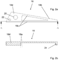
figures 2a et 2b montrent en vue de dessus et en coupe, un exemple de lame utilisée selon l'invention.
- the
figure 1 schematically illustrates a timepiece according to the invention, and - the
Figures 2a and 2b show in plan view and in section, an example of blade used according to the invention.
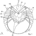
L'invention se rapporte à une pièce d'horlogerie comprenant un mécanisme de sonnerie. Il peut aussi bien s'agir d'un mécanisme de réveil, d'une répétition ou d'une grande-sonnerie que d'une montre musicale, c'est-à-dire munie d'un mécanisme de type boite à musique. Ce mécanisme de sonnerie est doté d'un disque 10 destiné à être entraîné en rotation par une source d'énergie autour d'un axe z et dans un plan P. Le disque 10 est muni sur au moins une de ses faces, d'au moins un ergot 12 en saillie dont le rôle sera précisé plus loin.The invention relates to a timepiece comprising a striking mechanism. It may as well be a waking mechanism, a repetition or a grand-ring that a musical watch, that is to say equipped with a mechanism like music box. This striking mechanism is provided with a
La source d'énergie est, typiquement, un barillet non représenté, de préférence dédié au mécanisme musical. On pourra associer un mouvement horloger de type quelconque à ce mécanisme. A titre d'exemple, le mouvement indique l'heure courante au moyen d'aiguilles 16. Le mouvement peut intégrer le mécanisme de sonnerie ou ce dernier peut être modulaire.The energy source is, typically, a not shown barrel, preferably dedicated to the musical mechanism. We can associate a movement watchmaker of any kind to this mechanism. For example, the movement indicates the current time by means of
Le mécanisme de sonnerie comprend également au moins une lame 18 comportant une portion d'encastrement 18a et une extrémité libre 18b. Par portion d'encastrement 18a, on entend l'extrémité de la partie de la lame qui participe à la vibration. La portion d'encastrement 18a jouxte une zone d'attache 18d qui, elle, est destinée à être liée rigidement au bâti de la pièce d'horlogerie. La lame sera décrite en détails ci-après. La lame 18 est agencée pour coopérer avec les ergots 12 en étant activée parallèlement à l'axe z au niveau ou au voisinage de l'extrémité libre 18b, afin de bénéficier d'un levier suffisant tout en ayant une déformation suffisante, à-même de générer une vibration audible. On notera que, selon l'exemple illustré, la lame est activée essentiellement selon une direction parallèle à l'axe z. De préférence, le mécanisme de sonnerie comprend plusieurs lames 18, capables de produire des sons différents.The striking mechanism also comprises at least one
Ainsi, lorsque le mécanisme de sonnerie est enclenché, le disque 10 est mis en rotation par la source d'énergie. Dans ce déplacement, les ergots 12 soulèvent la ou les lames 18 qui, en revenant soudainement à leur position de repos, vibrent en émettant un son. Ainsi, en fonction de la longueur des lames 18 et de leurs dispositions respectives en référence aux ergots 12, le mécanisme de sonnerie sonne une mélodie, un son ou une succession de sons pouvant correspondre à une information horaire, comme dans un mécanisme de type répétition. Le fonctionnement de ce genre de pièces étant de type connu, il ne sera pas décrit plus en détails.Thus, when the striking mechanism is engaged, the
Selon un exemple particulier de l'invention présenté sur les
Dans une première variante, chaque bras 18c d'une lame 18 définit des directions sécantes, le point d'intersection de ces directions étant situé au voisinage de l'extrémité libre 18b. Les bras 18c définissent ainsi une forme triangulaire, dont l'intérieur est ouvert. La pointe du triangle située au niveau de l'extrémité libre 18b peut être tronquée.In a first variant, each
En alternative, on pourrait aussi envisager que les bras 18c définissent des directions parallèles. Les bras 18c sont, au niveau de l'extrémité libre 18b, réunis par une portion supplémentaire, formant un U avec les bras 18c.Alternatively, one could also consider that the
On peut encore prévoir que la lame présente une surface continue, dont l'intérieur n'est pas ouvert. La lame n'a alors qu'un seul bras. La forme de la lame peut aussi bien être triangulaire, trapézoïdale ou rectangulaire.It can also be provided that the blade has a continuous surface, the interior of which is not open. The blade then has only one arm. The shape of the blade can be triangular, trapezoidal or rectangular.
Au niveau ou au voisinage de l'extrémité libre 18b, la lame peut présenter une protubérance 24 faisant saillie, orientée du côté des ergots 12. Les protubérances 24 et les ergots 12 sont agencés pour coopérer ensemble pour émettre un son. La masse de la protubérance peut être ajustée pour régler la fréquence du son produit par le timbre. On pourra noter que, le terme horloger désignant cette protubérance est le terme "plomb".At or near the
Quelle que soit la forme de la lame, la zone d'attache 18d peut être, pour sa fixation, traversée par une ouverture 20 permettant la fixation de la lame 18. Cette dernière est typiquement fixée au bâti de la pièce d'horlogerie, par vissage de préférence. On peut prévoir une deuxième ouverture 22, destinée à recevoir une deuxième vis ou une goupille de positionnement, afin de déterminer avec précision le positionnement des lames et d'éviter toute rotation de ces dernières. D'autres systèmes de fixation sont possibles, par serrage au moyen d'une pièce supplémentaire, par exemple.Whatever the shape of the blade, the
Le ou les bras 18c de la lame 18 peuvent être situés dans un plan parallèle au plan P, dans le plan de la portion d'encastrement 18a. Le ou les bras 18c peuvent aussi être orientés selon une direction oblique par rapport à la portion d'encastrement 18a, pour se rapprocher du disque 10 si celui-ci est disposé à un niveau différent (c'est-à-dire supérieur ou inférieur) par rapport à la portion d'encastrement 18a.The arm or
De préférence, la lame 18 est venue d'une pièce, y compris la portion d'encastrement. A titre d'exemples, la lame peut être réalisée en acier par des techniques de découpage, d'étampage, d'électroérosion ou de fraisage, ou en verre métallique, par exemple à base de zircone. Dans le cas d'une lame réalisée en verre métallique, on utilisera de préférence une technique de moulage d'une préforme suivie d'un usinage de sa forme définitive par électroérosion au fil, comme proposé dans la demande CH02112/10 au nom de la demanderesse.Preferably, the
Dans toutes ces configurations, la lame 18 présente, au niveau de sa portion d'encastrement 18a, une largeur supérieure à son épaisseur, la largeur étant la dimension orthogonale à l'axe longitudinal de la lame, située dans le plan P, et l'épaisseur étant la dimension orthogonale au plan P. La lame 18 présente ainsi une rigidité accrue, limitant les déformations en dehors de l'axe z lors de son actionnement par le ou les ergots 12 du disque, tout en conservant une bonne qualité du son produit. Les vibrations parasites observées avec les mécanismes de l'état de la technique sont considérablement réduites, voire supprimées.In all these configurations, the
Dans le cas d'un mécanisme de sonnerie capable de jouer plusieurs notes, au moyen d'une pluralité de lames, chaque lame 18 est de préférence indépendante l'une de l'autre et comprend sa propre zone d'attache 18d. Les portions d'encastrement 18a sont disposées autour de l'axe z sur le bâti de la pièce d'horlogerie, globalement concentriquement à cet axe. En variante, on peut regrouper plusieurs lames sur une zone d'attache 18d commune. Toutefois, selon la définition donnée ci-dessus, chaque lame comporte une portion d'encastrement 18a distincte. Dans ce cas, plusieurs lames peuvent être venues d'une pièce avec la zone d'attache.In the case of a striking mechanism capable of playing several notes, by means of a plurality of blades, each
Les lames 18 sont de préférence orientées selon des directions essentiellement radiales en référence à cet axe, de manière à ce que les extrémités libres soient situées au-dessus du disque.The
De manière avantageuse, l'actionnement des ergots 12 se fait ainsi selon une direction essentiellement orthogonale à la lame 18. Ceci est également rendu possible par la géométrie des lames 18. En outre, l'individualisation des lames 18 est intéressante en termes de design, mais également en termes de réglage et de service après-vente. On notera que l'orientation orthogonale en référence à la lame, de l'actionnement des ergots, est également préférable pour une pièce d'horlogerie qui n'aurait qu'une lame.Advantageously, the actuation of the
Par ailleurs, on relèvera que les ergots 12 peuvent être réalisés par des procédés de dépôts de couches, par exemple par croissance de nickel. De telles méthodes permettent de réaliser des ergots 12 de formes spéciales, afin de diminuer l'usure et d'améliorer la précision du contact entre les ergots 12 et les lames 18, ainsi que la précision de positionnement des ergots les uns par rapport aux autres. Par exemple, on peut réaliser des ergots de forme cylindrique, éventuellement tronquée dans la section par un méplat, sur un ou deux côtés. Le disque 10 et les ergots 12 sont avantageusement réalisés de manière monolithique, en nickel.Furthermore, it will be noted that the
Afin d'éviter tout blocage ou à-coup dans l'actionnement des lames 18, on peut prévoir que soit les ergots 12, soit les portions des bras 18c destinées à coopérer avec les ergots, soit les deux, présentent une zone biseautée, améliorant le glissement relatif des ergots 12 sur les bras 18c.In order to avoid any blockage or jerk in the actuation of the
Ainsi est proposée une nouvelle conformation de lames 18 pour mécanisme de sonnerie, permettant d'améliorer le comportement mécanique de la lame 18 par rapport aux contraintes subies et permettant de disposer plus librement les lames par rapport au disque.Thus is proposed a new configuration of
La description ci-dessus a été donnée à titre d'illustration non limitative de l'invention et l'homme du métier pourra envisager diverses variantes, sans toutefois sortir du cadre de l'invention tel que délimité par les revendications.The above description has been given by way of non-limiting illustration of the invention and the skilled person may consider various variants, without departing from the scope of the invention as delimited by the claims.
Claims (14)
- Timepiece comprising a striking-work equipped with- a disc (10) intended to be rotationally driven by a source of energy about an axis z and in a plane P, the disc (10) having, on at least one of its faces, at least one protruding catch (12),- at least one blade (18) having a mounting portion (18a) and a free end (18b), the blade (18) being arranged to cooperate with the catch or catches (12) by being constrained parallel to the z axis in an area near the free end (18b), the said blade (18) being arranged to produce a striking sound,in which the blade (18) has, at its mounting portion (18a), a width greater than its thickness, the width being the dimension orthogonal to the longitudinal axis of the blade, located in plane P, and the thickness being the dimension orthogonal to plane P, the said at least one blade being arranged so that the actuation of the said at least one catch (12) is performed in a direction essentially orthogonal to plane P, the said blade presenting at least two distinct arms (18c) connecting the free end (18b) of the blade (18) and the mounting portion (18a), the ends of the arms (18c) connected to the mounting portion (18a) being located substantially in a plane parallel to plane P.
- Timepiece according to claim 1, characterised in that the arms (18c) define secant directions, the point of intersection of these directions being located in the vicinity of the free end (18b).
- Timepiece according to claim 1, characterised in that the arms (18c) define parallel directions.
- Timepiece according to one of the preceding claims, characterised in that the blade also comprises an attachment zone (18d) traversed by at least one opening permits fixing of the blade (18).
- Timepiece according to one of the preceding claims, characterised in that the blade (18) is located in a plane parallel to plane P.
- Timepiece according to one of claims 1 to 5, characterised in that the blade is located in an oblique plane with respect to plane P.
- Timepiece according to one of the preceding claims, characterised in that the blade is integrally formed, including the attachment zone (18d).
- Timepiece according to one of the preceding claims, comprising a plurality of blades (18), each blade (18) being independent of each other and comprising its own attachment zone (18d).
- Timepiece according to one of claims 1 to 7, comprising a plurality of blades (18), several blades sharing a common attachment zone (18d).
- Timepiece according to one of claims 8 and 9, characterised in that the mounting portions of the blades (18) are arranged substantially concentrically to the axis z and that the blades are oriented in essentially radial directions with reference to this axis.
- Timepiece according to one of the preceding claims, characterised in that the catches (12) are made of nickel deposited on the disc.
- Timepiece according to claim 11, characterised in that the disc (10) and the catches (12) are monolithically made of nickel.
- Timepiece according to one of the preceding claims, characterised in that either the catches or the portions of the arms (18c) intended to cooperate with the catches, or both, have a bevelled zone.
- Timepiece according to one of the preceding claims, characterised in that the said at least one blade (18) is made of metallic glass.
Applications Claiming Priority (1)
| Application Number | Priority Date | Filing Date | Title |
|---|---|---|---|
| CH00395/11A CH704593B1 (en) | 2011-03-08 | 2011-03-08 | Timepiece fitted with a striking mechanism. |
Publications (3)
| Publication Number | Publication Date |
|---|---|
| EP2498144A2 EP2498144A2 (en) | 2012-09-12 |
| EP2498144A3 EP2498144A3 (en) | 2014-04-02 |
| EP2498144B1 true EP2498144B1 (en) | 2019-05-22 |
Family
ID=45566938
Family Applications (1)
| Application Number | Title | Priority Date | Filing Date |
|---|---|---|---|
| EP12155255.8A Active EP2498144B1 (en) | 2011-03-08 | 2012-02-13 | Timepiece equipped with a strike mechanism |
Country Status (2)
| Country | Link |
|---|---|
| EP (1) | EP2498144B1 (en) |
| CH (1) | CH704593B1 (en) |
Families Citing this family (2)
| Publication number | Priority date | Publication date | Assignee | Title |
|---|---|---|---|---|
| CH707078A1 (en) * | 2012-10-15 | 2014-04-15 | Société Anonyme De La Manufacture D Horlogerie Audemars Piguet & Cie | Stamp for striking work of a timepiece. |
| CH707110B1 (en) * | 2012-10-17 | 2017-02-28 | Reuge Sa | Musical watch. |
Family Cites Families (7)
| Publication number | Priority date | Publication date | Assignee | Title |
|---|---|---|---|---|
| CH211210A (en) | 1938-07-01 | 1940-08-31 | Pirelli | Device for determining the size of masks appropriate for various individuals. |
| DE1713518U (en) * | 1955-05-02 | 1955-12-22 | Kienzle Uhrenfabriken Ag | CLOCKWORK. |
| CH343214A (en) * | 1957-12-27 | 1959-12-15 | Techna Anstalt Fuer Verwertung | Method for tuning a musical room vibrating reed keyboard and keyboard obtained by this method |
| JPS4511967Y1 (en) * | 1966-10-12 | 1970-05-27 | ||
| CH481447A (en) * | 1968-09-19 | 1969-11-15 | Techna Anstalt Fuer Verwertung | Method of fixing a shock absorber on a vibrating blade of a musical movement keyboard and blade resulting from this process |
| JP4833289B2 (en) | 2006-07-10 | 2011-12-07 | モントレー ブレゲ・エス アー | Music module for clock movement |
| US7813227B2 (en) * | 2007-10-23 | 2010-10-12 | Montres Breguet S.A. | Musical module for a watch movement |
-
2011
- 2011-03-08 CH CH00395/11A patent/CH704593B1/en not_active IP Right Cessation
-
2012
- 2012-02-13 EP EP12155255.8A patent/EP2498144B1/en active Active
Non-Patent Citations (1)
| Title |
|---|
| None * |
Also Published As
| Publication number | Publication date |
|---|---|
| EP2498144A2 (en) | 2012-09-12 |
| CH704593A2 (en) | 2012-09-14 |
| EP2498144A3 (en) | 2014-04-02 |
| CH704593B1 (en) | 2015-09-15 |
Similar Documents
| Publication | Publication Date | Title |
|---|---|---|
| EP2339412B1 (en) | Chiming mechanism of a watch | |
| EP1837719B1 (en) | Balance for a clock movement | |
| EP2596407A1 (en) | Balance having inertia adjustment using an insert | |
| EP2102717A2 (en) | Mechanical oscillator for timepiece | |
| EP2917787B1 (en) | Clock movement having a balance and a hairspring | |
| EP2290476A1 (en) | Isochronism corrector for a timepiece escapement and anescapement equipped with such a corrector | |
| EP3115852A1 (en) | Timepiece component having a part with improved welding surface | |
| EP2690507A1 (en) | Holorological hairspring | |
| EP2781965B1 (en) | Frame for a clockwork | |
| CH708095A2 (en) | striking mechanism provided with selection means of vibratory mode of a stamp. | |
| EP2498144B1 (en) | Timepiece equipped with a strike mechanism | |
| CH684731B5 (en) | piezoelectric motor. | |
| EP3112950B1 (en) | Manufacturing method comprising a modified bar turning step | |
| EP2320280A1 (en) | Anchor for clock escapement system | |
| EP2362278A1 (en) | Hammer for a stricking mechanism of a watch | |
| EP1870784A2 (en) | Micro-engineered mobile with impact controlled rotation | |
| EP3657269A1 (en) | Resonant member for a chiming mechanism of a watch or a music box | |
| EP3537228B1 (en) | Device for adjusting the vibration frequency of a bell of a chiming mechanism | |
| EP2984525B1 (en) | Timepiece comprising a chiming device | |
| CH703462A2 (en) | Inertia adjustable bogie beam assembly producing method for watch, involves inserting insert into housing by restricting maintaining unit in insertion position and releasing unit to maintaining position after complete insertion of insert | |
| EP1695154B1 (en) | Bearing unit equipped with a bearing and a regulator | |
| CH716149A1 (en) | Clockwork movement comprising at least one gong. | |
| EP2590034B1 (en) | Chiming watch | |
| CH715579A2 (en) | Resonant organ for a striking mechanism of a watch or a music box. | |
| CH717200A2 (en) | Oscillating winding weight fitted with a decorative element for an automatic movement of a timepiece. |
Legal Events
| Date | Code | Title | Description |
|---|---|---|---|
| PUAI | Public reference made under article 153(3) epc to a published international application that has entered the european phase |
Free format text: ORIGINAL CODE: 0009012 |
|
| AK | Designated contracting states |
Kind code of ref document: A2 Designated state(s): AL AT BE BG CH CY CZ DE DK EE ES FI FR GB GR HR HU IE IS IT LI LT LU LV MC MK MT NL NO PL PT RO RS SE SI SK SM TR |
|
| AX | Request for extension of the european patent |
Extension state: BA ME |
|
| RIC1 | Information provided on ipc code assigned before grant |
Ipc: G04B 21/08 20060101AFI20131107BHEP Ipc: G04B 23/02 20060101ALI20131107BHEP |
|
| PUAL | Search report despatched |
Free format text: ORIGINAL CODE: 0009013 |
|
| AK | Designated contracting states |
Kind code of ref document: A3 Designated state(s): AL AT BE BG CH CY CZ DE DK EE ES FI FR GB GR HR HU IE IS IT LI LT LU LV MC MK MT NL NO PL PT RO RS SE SI SK SM TR |
|
| AX | Request for extension of the european patent |
Extension state: BA ME |
|
| RIC1 | Information provided on ipc code assigned before grant |
Ipc: G04B 21/08 20060101AFI20140225BHEP Ipc: G04B 23/02 20060101ALI20140225BHEP |
|
| 17P | Request for examination filed |
Effective date: 20140916 |
|
| RBV | Designated contracting states (corrected) |
Designated state(s): AL AT BE BG CH CY CZ DE DK EE ES FI FR GB GR HR HU IE IS IT LI LT LU LV MC MK MT NL NO PL PT RO RS SE SI SK SM TR |
|
| GRAP | Despatch of communication of intention to grant a patent |
Free format text: ORIGINAL CODE: EPIDOSNIGR1 |
|
| STAA | Information on the status of an ep patent application or granted ep patent |
Free format text: STATUS: GRANT OF PATENT IS INTENDED |
|
| INTG | Intention to grant announced |
Effective date: 20181213 |
|
| GRAS | Grant fee paid |
Free format text: ORIGINAL CODE: EPIDOSNIGR3 |
|
| GRAA | (expected) grant |
Free format text: ORIGINAL CODE: 0009210 |
|
| STAA | Information on the status of an ep patent application or granted ep patent |
Free format text: STATUS: THE PATENT HAS BEEN GRANTED |
|
| AK | Designated contracting states |
Kind code of ref document: B1 Designated state(s): AL AT BE BG CH CY CZ DE DK EE ES FI FR GB GR HR HU IE IS IT LI LT LU LV MC MK MT NL NO PL PT RO RS SE SI SK SM TR |
|
| REG | Reference to a national code |
Ref country code: GB Ref legal event code: FG4D Free format text: NOT ENGLISH |
|
| REG | Reference to a national code |
Ref country code: CH Ref legal event code: EP |
|
| REG | Reference to a national code |
Ref country code: IE Ref legal event code: FG4D Free format text: LANGUAGE OF EP DOCUMENT: FRENCH |
|
| REG | Reference to a national code |
Ref country code: DE Ref legal event code: R096 Ref document number: 602012060290 Country of ref document: DE |
|
| REG | Reference to a national code |
Ref country code: AT Ref legal event code: REF Ref document number: 1136864 Country of ref document: AT Kind code of ref document: T Effective date: 20190615 |
|
| REG | Reference to a national code |
Ref country code: CH Ref legal event code: NV Representative=s name: E-PATENT S.A., CH |
|
| REG | Reference to a national code |
Ref country code: NL Ref legal event code: MP Effective date: 20190522 |
|
| REG | Reference to a national code |
Ref country code: LT Ref legal event code: MG4D |
|
| PG25 | Lapsed in a contracting state [announced via postgrant information from national office to epo] |
Ref country code: LT Free format text: LAPSE BECAUSE OF FAILURE TO SUBMIT A TRANSLATION OF THE DESCRIPTION OR TO PAY THE FEE WITHIN THE PRESCRIBED TIME-LIMIT Effective date: 20190522 Ref country code: HR Free format text: LAPSE BECAUSE OF FAILURE TO SUBMIT A TRANSLATION OF THE DESCRIPTION OR TO PAY THE FEE WITHIN THE PRESCRIBED TIME-LIMIT Effective date: 20190522 Ref country code: FI Free format text: LAPSE BECAUSE OF FAILURE TO SUBMIT A TRANSLATION OF THE DESCRIPTION OR TO PAY THE FEE WITHIN THE PRESCRIBED TIME-LIMIT Effective date: 20190522 Ref country code: AL Free format text: LAPSE BECAUSE OF FAILURE TO SUBMIT A TRANSLATION OF THE DESCRIPTION OR TO PAY THE FEE WITHIN THE PRESCRIBED TIME-LIMIT Effective date: 20190522 Ref country code: NO Free format text: LAPSE BECAUSE OF FAILURE TO SUBMIT A TRANSLATION OF THE DESCRIPTION OR TO PAY THE FEE WITHIN THE PRESCRIBED TIME-LIMIT Effective date: 20190822 Ref country code: SE Free format text: LAPSE BECAUSE OF FAILURE TO SUBMIT A TRANSLATION OF THE DESCRIPTION OR TO PAY THE FEE WITHIN THE PRESCRIBED TIME-LIMIT Effective date: 20190522 Ref country code: PT Free format text: LAPSE BECAUSE OF FAILURE TO SUBMIT A TRANSLATION OF THE DESCRIPTION OR TO PAY THE FEE WITHIN THE PRESCRIBED TIME-LIMIT Effective date: 20190922 Ref country code: ES Free format text: LAPSE BECAUSE OF FAILURE TO SUBMIT A TRANSLATION OF THE DESCRIPTION OR TO PAY THE FEE WITHIN THE PRESCRIBED TIME-LIMIT Effective date: 20190522 Ref country code: NL Free format text: LAPSE BECAUSE OF FAILURE TO SUBMIT A TRANSLATION OF THE DESCRIPTION OR TO PAY THE FEE WITHIN THE PRESCRIBED TIME-LIMIT Effective date: 20190522 |
|
| PG25 | Lapsed in a contracting state [announced via postgrant information from national office to epo] |
Ref country code: RS Free format text: LAPSE BECAUSE OF FAILURE TO SUBMIT A TRANSLATION OF THE DESCRIPTION OR TO PAY THE FEE WITHIN THE PRESCRIBED TIME-LIMIT Effective date: 20190522 Ref country code: BG Free format text: LAPSE BECAUSE OF FAILURE TO SUBMIT A TRANSLATION OF THE DESCRIPTION OR TO PAY THE FEE WITHIN THE PRESCRIBED TIME-LIMIT Effective date: 20190822 Ref country code: LV Free format text: LAPSE BECAUSE OF FAILURE TO SUBMIT A TRANSLATION OF THE DESCRIPTION OR TO PAY THE FEE WITHIN THE PRESCRIBED TIME-LIMIT Effective date: 20190522 Ref country code: GR Free format text: LAPSE BECAUSE OF FAILURE TO SUBMIT A TRANSLATION OF THE DESCRIPTION OR TO PAY THE FEE WITHIN THE PRESCRIBED TIME-LIMIT Effective date: 20190823 |
|
| REG | Reference to a national code |
Ref country code: AT Ref legal event code: MK05 Ref document number: 1136864 Country of ref document: AT Kind code of ref document: T Effective date: 20190522 |
|
| PG25 | Lapsed in a contracting state [announced via postgrant information from national office to epo] |
Ref country code: EE Free format text: LAPSE BECAUSE OF FAILURE TO SUBMIT A TRANSLATION OF THE DESCRIPTION OR TO PAY THE FEE WITHIN THE PRESCRIBED TIME-LIMIT Effective date: 20190522 Ref country code: SK Free format text: LAPSE BECAUSE OF FAILURE TO SUBMIT A TRANSLATION OF THE DESCRIPTION OR TO PAY THE FEE WITHIN THE PRESCRIBED TIME-LIMIT Effective date: 20190522 Ref country code: AT Free format text: LAPSE BECAUSE OF FAILURE TO SUBMIT A TRANSLATION OF THE DESCRIPTION OR TO PAY THE FEE WITHIN THE PRESCRIBED TIME-LIMIT Effective date: 20190522 Ref country code: DK Free format text: LAPSE BECAUSE OF FAILURE TO SUBMIT A TRANSLATION OF THE DESCRIPTION OR TO PAY THE FEE WITHIN THE PRESCRIBED TIME-LIMIT Effective date: 20190522 Ref country code: RO Free format text: LAPSE BECAUSE OF FAILURE TO SUBMIT A TRANSLATION OF THE DESCRIPTION OR TO PAY THE FEE WITHIN THE PRESCRIBED TIME-LIMIT Effective date: 20190522 Ref country code: CZ Free format text: LAPSE BECAUSE OF FAILURE TO SUBMIT A TRANSLATION OF THE DESCRIPTION OR TO PAY THE FEE WITHIN THE PRESCRIBED TIME-LIMIT Effective date: 20190522 |
|
| REG | Reference to a national code |
Ref country code: DE Ref legal event code: R097 Ref document number: 602012060290 Country of ref document: DE |
|
| PG25 | Lapsed in a contracting state [announced via postgrant information from national office to epo] |
Ref country code: SM Free format text: LAPSE BECAUSE OF FAILURE TO SUBMIT A TRANSLATION OF THE DESCRIPTION OR TO PAY THE FEE WITHIN THE PRESCRIBED TIME-LIMIT Effective date: 20190522 Ref country code: IT Free format text: LAPSE BECAUSE OF FAILURE TO SUBMIT A TRANSLATION OF THE DESCRIPTION OR TO PAY THE FEE WITHIN THE PRESCRIBED TIME-LIMIT Effective date: 20190522 |
|
| PLBE | No opposition filed within time limit |
Free format text: ORIGINAL CODE: 0009261 |
|
| STAA | Information on the status of an ep patent application or granted ep patent |
Free format text: STATUS: NO OPPOSITION FILED WITHIN TIME LIMIT |
|
| PG25 | Lapsed in a contracting state [announced via postgrant information from national office to epo] |
Ref country code: TR Free format text: LAPSE BECAUSE OF FAILURE TO SUBMIT A TRANSLATION OF THE DESCRIPTION OR TO PAY THE FEE WITHIN THE PRESCRIBED TIME-LIMIT Effective date: 20190522 |
|
| 26N | No opposition filed |
Effective date: 20200225 |
|
| PG25 | Lapsed in a contracting state [announced via postgrant information from national office to epo] |
Ref country code: PL Free format text: LAPSE BECAUSE OF FAILURE TO SUBMIT A TRANSLATION OF THE DESCRIPTION OR TO PAY THE FEE WITHIN THE PRESCRIBED TIME-LIMIT Effective date: 20190522 |
|
| PG25 | Lapsed in a contracting state [announced via postgrant information from national office to epo] |
Ref country code: SI Free format text: LAPSE BECAUSE OF FAILURE TO SUBMIT A TRANSLATION OF THE DESCRIPTION OR TO PAY THE FEE WITHIN THE PRESCRIBED TIME-LIMIT Effective date: 20190522 |
|
| REG | Reference to a national code |
Ref country code: DE Ref legal event code: R119 Ref document number: 602012060290 Country of ref document: DE |
|
| GBPC | Gb: european patent ceased through non-payment of renewal fee |
Effective date: 20200213 |
|
| REG | Reference to a national code |
Ref country code: BE Ref legal event code: MM Effective date: 20200229 |
|
| PG25 | Lapsed in a contracting state [announced via postgrant information from national office to epo] |
Ref country code: MC Free format text: LAPSE BECAUSE OF FAILURE TO SUBMIT A TRANSLATION OF THE DESCRIPTION OR TO PAY THE FEE WITHIN THE PRESCRIBED TIME-LIMIT Effective date: 20190522 Ref country code: LU Free format text: LAPSE BECAUSE OF NON-PAYMENT OF DUE FEES Effective date: 20200213 |
|
| PG25 | Lapsed in a contracting state [announced via postgrant information from national office to epo] |
Ref country code: DE Free format text: LAPSE BECAUSE OF NON-PAYMENT OF DUE FEES Effective date: 20200901 Ref country code: IE Free format text: LAPSE BECAUSE OF NON-PAYMENT OF DUE FEES Effective date: 20200213 Ref country code: GB Free format text: LAPSE BECAUSE OF NON-PAYMENT OF DUE FEES Effective date: 20200213 Ref country code: FR Free format text: LAPSE BECAUSE OF NON-PAYMENT OF DUE FEES Effective date: 20200229 |
|
| PG25 | Lapsed in a contracting state [announced via postgrant information from national office to epo] |
Ref country code: BE Free format text: LAPSE BECAUSE OF NON-PAYMENT OF DUE FEES Effective date: 20200229 |
|
| PG25 | Lapsed in a contracting state [announced via postgrant information from national office to epo] |
Ref country code: MT Free format text: LAPSE BECAUSE OF FAILURE TO SUBMIT A TRANSLATION OF THE DESCRIPTION OR TO PAY THE FEE WITHIN THE PRESCRIBED TIME-LIMIT Effective date: 20190522 Ref country code: CY Free format text: LAPSE BECAUSE OF FAILURE TO SUBMIT A TRANSLATION OF THE DESCRIPTION OR TO PAY THE FEE WITHIN THE PRESCRIBED TIME-LIMIT Effective date: 20190522 |
|
| PG25 | Lapsed in a contracting state [announced via postgrant information from national office to epo] |
Ref country code: MK Free format text: LAPSE BECAUSE OF FAILURE TO SUBMIT A TRANSLATION OF THE DESCRIPTION OR TO PAY THE FEE WITHIN THE PRESCRIBED TIME-LIMIT Effective date: 20190522 Ref country code: IS Free format text: LAPSE BECAUSE OF FAILURE TO SUBMIT A TRANSLATION OF THE DESCRIPTION OR TO PAY THE FEE WITHIN THE PRESCRIBED TIME-LIMIT Effective date: 20190922 |
|
| PGFP | Annual fee paid to national office [announced via postgrant information from national office to epo] |
Ref country code: CH Payment date: 20230307 Year of fee payment: 12 |