EP2498067B1 - Coupling for a Position Indication Device - Google Patents
Coupling for a Position Indication Device Download PDFInfo
- Publication number
- EP2498067B1 EP2498067B1 EP12158306.6A EP12158306A EP2498067B1 EP 2498067 B1 EP2498067 B1 EP 2498067B1 EP 12158306 A EP12158306 A EP 12158306A EP 2498067 B1 EP2498067 B1 EP 2498067B1
- Authority
- EP
- European Patent Office
- Prior art keywords
- grommet
- position indication
- bearing
- connecting member
- accordance
- Prior art date
- Legal status (The legal status is an assumption and is not a legal conclusion. Google has not performed a legal analysis and makes no representation as to the accuracy of the status listed.)
- Active
Links
Images

Classifications
-
- F—MECHANICAL ENGINEERING; LIGHTING; HEATING; WEAPONS; BLASTING
- F01—MACHINES OR ENGINES IN GENERAL; ENGINE PLANTS IN GENERAL; STEAM ENGINES
- F01D—NON-POSITIVE DISPLACEMENT MACHINES OR ENGINES, e.g. STEAM TURBINES
- F01D25/00—Component parts, details, or accessories, not provided for in, or of interest apart from, other groups
- F01D25/28—Supporting or mounting arrangements, e.g. for turbine casing
-
- G—PHYSICS
- G01—MEASURING; TESTING
- G01D—MEASURING NOT SPECIALLY ADAPTED FOR A SPECIFIC VARIABLE; ARRANGEMENTS FOR MEASURING TWO OR MORE VARIABLES NOT COVERED IN A SINGLE OTHER SUBCLASS; TARIFF METERING APPARATUS; MEASURING OR TESTING NOT OTHERWISE PROVIDED FOR
- G01D11/00—Component parts of measuring arrangements not specially adapted for a specific variable
- G01D11/02—Bearings or suspensions for moving parts
-
- F—MECHANICAL ENGINEERING; LIGHTING; HEATING; WEAPONS; BLASTING
- F16—ENGINEERING ELEMENTS AND UNITS; GENERAL MEASURES FOR PRODUCING AND MAINTAINING EFFECTIVE FUNCTIONING OF MACHINES OR INSTALLATIONS; THERMAL INSULATION IN GENERAL
- F16F—SPRINGS; SHOCK-ABSORBERS; MEANS FOR DAMPING VIBRATION
- F16F1/00—Springs
- F16F1/36—Springs made of rubber or other material having high internal friction, e.g. thermoplastic elastomers
- F16F1/373—Springs made of rubber or other material having high internal friction, e.g. thermoplastic elastomers characterised by having a particular shape
- F16F1/3732—Springs made of rubber or other material having high internal friction, e.g. thermoplastic elastomers characterised by having a particular shape having an annular or the like shape, e.g. grommet-type resilient mountings
-
- F—MECHANICAL ENGINEERING; LIGHTING; HEATING; WEAPONS; BLASTING
- F16—ENGINEERING ELEMENTS AND UNITS; GENERAL MEASURES FOR PRODUCING AND MAINTAINING EFFECTIVE FUNCTIONING OF MACHINES OR INSTALLATIONS; THERMAL INSULATION IN GENERAL
- F16C—SHAFTS; FLEXIBLE SHAFTS; ELEMENTS OR CRANKSHAFT MECHANISMS; ROTARY BODIES OTHER THAN GEARING ELEMENTS; BEARINGS
- F16C11/00—Pivots; Pivotal connections
- F16C11/04—Pivotal connections
- F16C11/06—Ball-joints; Other joints having more than one degree of angular freedom, i.e. universal joints
- F16C11/08—Ball-joints; Other joints having more than one degree of angular freedom, i.e. universal joints with resilient bearings
-
- G—PHYSICS
- G01—MEASURING; TESTING
- G01D—MEASURING NOT SPECIALLY ADAPTED FOR A SPECIFIC VARIABLE; ARRANGEMENTS FOR MEASURING TWO OR MORE VARIABLES NOT COVERED IN A SINGLE OTHER SUBCLASS; TARIFF METERING APPARATUS; MEASURING OR TESTING NOT OTHERWISE PROVIDED FOR
- G01D5/00—Mechanical means for transferring the output of a sensing member; Means for converting the output of a sensing member to another variable where the form or nature of the sensing member does not constrain the means for converting; Transducers not specially adapted for a specific variable
- G01D5/12—Mechanical means for transferring the output of a sensing member; Means for converting the output of a sensing member to another variable where the form or nature of the sensing member does not constrain the means for converting; Transducers not specially adapted for a specific variable using electric or magnetic means
- G01D5/14—Mechanical means for transferring the output of a sensing member; Means for converting the output of a sensing member to another variable where the form or nature of the sensing member does not constrain the means for converting; Transducers not specially adapted for a specific variable using electric or magnetic means influencing the magnitude of a current or voltage
- G01D5/20—Mechanical means for transferring the output of a sensing member; Means for converting the output of a sensing member to another variable where the form or nature of the sensing member does not constrain the means for converting; Transducers not specially adapted for a specific variable using electric or magnetic means influencing the magnitude of a current or voltage by varying inductance, e.g. by a movable armature
- G01D5/22—Mechanical means for transferring the output of a sensing member; Means for converting the output of a sensing member to another variable where the form or nature of the sensing member does not constrain the means for converting; Transducers not specially adapted for a specific variable using electric or magnetic means influencing the magnitude of a current or voltage by varying inductance, e.g. by a movable armature differentially influencing two coils
- G01D5/2291—Linear or rotary variable differential transformers (LVDTs/RVDTs) having a single primary coil and two secondary coils
-
- Y—GENERAL TAGGING OF NEW TECHNOLOGICAL DEVELOPMENTS; GENERAL TAGGING OF CROSS-SECTIONAL TECHNOLOGIES SPANNING OVER SEVERAL SECTIONS OF THE IPC; TECHNICAL SUBJECTS COVERED BY FORMER USPC CROSS-REFERENCE ART COLLECTIONS [XRACs] AND DIGESTS
- Y10—TECHNICAL SUBJECTS COVERED BY FORMER USPC
- Y10T—TECHNICAL SUBJECTS COVERED BY FORMER US CLASSIFICATION
- Y10T29/00—Metal working
- Y10T29/49—Method of mechanical manufacture
- Y10T29/49826—Assembling or joining
- Y10T29/49947—Assembling or joining by applying separate fastener
Definitions
- the subject matter described herein relates generally to a position indication system, and more specifically, to a vibration tolerant bearing mechanism for use in a position indication system.
- Linear actuators are included in many residential and commercial applications. For example, positions of valves included within a steam turbine may be adjusted using linear actuators. Furthermore, a position of the valve may be measured using a position indication device, for example, a linear variable differential transformer (LVDT).
- a steam valve position indication system may utilize a stud coupled to the steam valve in combination with a rod end bearing arrangement to secure a linear transducer rod of the LVDT to the steam valve.
- the rod end bearing arrangement may include a bearing ball and a bearing housing.
- Wear to the rod end bearing arrangement may result in insecure coupling of the rod end bearing arrangement and the stud. This allows relative motion to occur between the metal stud and metal rod end bearing housing. The relative motion may result in fretting wear of the stud, and ultimately, to failure of the stud. The relative motion may also result in a noisy feedback signal from LVDT to the control system.
- the rod end bearing arrangement may be greased and/or materials used to form the bearing ball and the bearing housing may be varied.
- elastomeric rod end bearing arrangements are commercially available, however, characteristics of a typical elastomeric rod end bearing arrangement are not adjustable based on a preload compression level.
- US 2008/041145 A1 discloses a steam valve for steam turbine environments, comprising a LVDT linear position sensor.
- the valve is actuated in rotation, whereby the movement of a rotating connecting rod is translated through a pinion gear to a linear movement of a sensor rod, said linear movement being detected by the LVDT linear position sensor.
- US-A-2009/317027 concerns an actuator assembly for driving a control element, such as a flight control surface, and a position sensing assembly that generates an output signal that reflects the position of the control element.
- the position sensor assembly includes a bearing element and a helically shaped rotational member to drive a portion of the sensor assembly so that backlash in the position sensing assembly is minimised.
- GB2060812 discloses a vibration isolator used to fasten two components of a structure together in such a way as to reduce the transmission of vibration and noise between the two components. To do so, the isolator is proposed in the form of resilient elastomeric bushings or grommets.
- the present invention provides a position indication system as defined in appended claim 1, and a method for using the position indication system as defined in appended claim 11.
- a position indication system for measuring a position of a steam valve.
- the system includes a control valve bracket coupled to the steam valve and including a first connecting member.
- the system also includes a position indication device including a second connecting member.
- the system also includes a bearing device configured to couple the first connecting member to the second connecting member.
- the bearing device includes a bearing housing that includes a first opening defined therein.
- the bearing device also includes a grommet that includes a second opening defined therein. The grommet is configured for positioning within the first opening, the first member configured to extend through the second opening and to couple the bearing device to the bracket.
- a method for coupling a steam valve to a position indication device using a bearing device includes a cantilevered stud extending from the steam valve configured to interact with a cooperating member.
- the bearing device includes a bearing housing and a grommet.
- the bearing housing includes a bearing housing opening defined therein and the grommet includes a grommet opening defined therein.
- the method includes configuring the grommet and the bearing housing to receive the cantilevered stud, wherein the grommet is positioned between the cantilevered stud and the bearing housing.
- the method also includes configuring the cooperating member and the cantilevered stud to apply a compression force on the grommet.
- the methods, systems, and devices described herein facilitate coupling a position indication device to an apparatus using a bearing device in a manner that allows for proper alignment of the position indication device and the apparatus. Proper alignment facilitates accurate operation of the position indication device and reduced wear. Furthermore, the methods, systems, and devices described herein facilitate adjusting a natural frequency of the bearing device in order to prevent the natural frequency from matching a forcing frequency of the apparatus. Furthermore, a useful life of the bearing device is increased when compared to other bearing devices that do not include vibration damping capabilities.
- the disclosure is described as applied to example embodiments, namely, methods, systems, and devices for coupling a position feedback device to a control valve associated with a steam turbine.
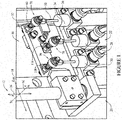
- FIG. 1 is an illustration of an example position indication system 10.
- a Cartesian coordinate system 12 including an X-axis 14, a Y-axis 16, and a Z-axis 18 is provided for use in describing position indication system 10.
- position indication system 10 is included within a steam turbine for measuring a position of a steam valve 20.
- position indication system 10 includes a plurality of position indication devices 22 coupled to a control valve housing 24.
- the plurality of position indication devices 22 may include a first position indication device 26, a second position indication device 28, and a third position indication device 30.
- Position indication devices 26, 28, and 30 may include, for example, a linear variable differential transformer (LVDT), a rotary variable differential transformer (RVDT), and/or any other displacement measuring device.
- LVDT linear variable differential transformer
- RVDT rotary variable differential transformer
- the plurality of position indication devices 22 are also coupled to a control valve bracket 32.
- Control valve bracket 32 is coupled to steam valve 20.
- control valve bracket 32 translates along Y-axis 16 as steam valve 20 is actuated between an open and a closed position.
- position indication system 10 may be included within any system and/or device for measuring a position of a component within the system and/or device.
- first position indication device 26 includes a first connecting member, for example, a first linear transducer rod 50.
- first linear transducer rod 50 extends from first position indication device 26 in a direction parallel to Y-axis 16.
- Control valve bracket 32 includes a second connecting member, for example, a first stud 60.
- first stud 60 extends from control valve bracket 32 in a direction parallel to X-axis 14.
- position indication system 10 includes a bearing device 70 for coupling first linear transducer rod 50 to first stud 60.
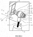
- FIG. 2 is another illustration of bearing device 70.
- Figure 3 is an exploded view of bearing device 70.
- bearing device 70 may be used with position indication system 10 (shown in Figure 1 ).
- bearing device 70 couples a position indication device, for example, position indication device 26, to an apparatus, for example, control valve bracket 32.
- bearing device 70 includes a bearing housing 72 and a grommet 74.
- Bearing housing 72 includes a first opening 86 and a second opening 88 defined therein.
- Grommet 74 includes a grommet opening 90 defined therein.
- grommet 74 is positioned within first opening 86 of bearing housing 72.
- First stud 60 extends through grommet opening 90. When assembled, grommet 74 is positioned between bearing housing 72 and first stud 60.
- first stud 60 includes a threaded portion 100 and a restraining portion 102.
- restraining portion 102 may be in the form of a flange that extends radially outwardly from first stud 60.
- restraining portion 102 may include a pin (not shown) that extends radially through, and outward from, first stud 60.
- restraining portion 102 may also include a first washer 106, which in combination with the flange and/or pin, fixes the position of grommet 74 with respect to first stud 60.
- threaded portion 100 is configured to extend through grommet opening 90.
- a cooperating member 104 for example, in the form of a lock nut or any other suitable fastener, interacts with threaded portion 100 of first stud 60 to secure bearing device 70 to first stud 60.
- grommet 74 is positioned between restraining portion 102 and cooperating member 104.
- bearing device 70 may also include a second washer 108, positioned between cooperating member 104 and grommet 74.
- Torque applied to at least one of cooperating member 104 and first stud 60 is converted to a compression force on grommet 74.
- the compression force acts on grommet 74 in a direction parallel to X-axis 14. Varying the compression force applied to grommet 74 facilitates controlling a natural frequency of bearing device 70. Issues may arise if the natural frequency of bearing device 70 is substantially similar to a forced frequency applied to bearing device 70 by, for example, control valve 20 and/or control valve housing 24.
- grommet 74 may include a first shoulder 110 to prevent bearing housing 72 from contacting restraining portion 102 and/or a second shoulder 112 to prevent bearing housing 72 from contacting either second washer 108 or cooperating member 104.
- grommet 74 may be a smooth, shoulder-less grommet. The compression force acting on grommet 74 will cause expansion of the grommet between bearing housing 72 and restraining portion 102 radially outward from X-axis 14, which will also prevent bearing housing 72 from contacting restraining portion 102.
- first linear transducer rod 50 is inserted into second opening 88 to couple first linear transducer rod 50 to bearing housing 72.
- First linear transducer rod 50 may be threaded and configured to couple with cooperating threads (not shown) included within second opening 88.
- bearing housing 72 may include a set-screw 114 for securing linear transducer rod 50 within second opening 88.
- first linear transducer rod 50 may be coupled to bearing housing 72 in any suitable manner.
- first stud 60 is configured to provide adjustability of a position of bearing housing 72 in a direction parallel to X-axis 14. Bearing housing 72 is adjusted in a direction parallel to X-axis 14 such that second opening 88 is properly aligned with transducer rod 50. Proper alignment of transducer rod 50 and second opening 88 allows transducer rod 50 to freely move in a direction parallel to Y-axis 16.
- position indication system 10 in addition to first position indication device 26 and first stud 60, position indication system 10 also includes second position indication device 28, third position indication device 30, and a plurality of bearing devices 70.
- Control valve bracket 32 also includes a second stud 116 and a third stud 118.
- bearing device 70 couples second position indication device 28 to second stud 116 and another bearing device 70 couples third position indication device 30 to third stud 118.
- grommet 74 prevents contact between bearing housing 72 and first stud 60.
- bearing housing 72 and first stud 60 are metal. Metal-on-metal contact in a high vibration application, such as a steam turbine valve actuator, may result in premature wear of components.
- grommet 74 is manufactured from a polymer configured to eliminate metal-on-metal contact between bearing housing 72 and first stud 60.
- grommet 74 may be manufactured from a fluoroelastomer, for example, but not limited to, Viton®. Viton® is a registered trademark of DuPont Performance Elastomers LLC.
- grommet 74 provides damping of vibration from first stud 60.
- grommet 74 compensates for minor misalignment between transducer rod 50 and bearing housing 72.
- grommet 74 is sufficiently stiff so as to restrict rotation of bearing housing 72 about Y-axis 16 and so as to not induce noise into an output of position indication device 26.
- grommet 74 may be resistant to radiation to allow bearing device 70 to be used in a nuclear application, for example, a steam turbine included within a nuclear power generation facility.
- grommet 74 may be resistant to damage from fluids present in a steam turbine application, for example, resistant to damage from a phosphate ester hydraulic fluid.
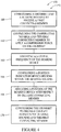
- FIG 4 is a flow chart 150 of a method 152 for coupling components included in a position indication system, for example, position indication system 10 (shown in Figure 1 ), and more specifically, for coupling an apparatus to a position indication device using a bearing device.
- position indication system 10 includes bearing device 70, which includes bearing housing 72 and grommet 74 (all shown in Figure 2 ).
- Bearing housing 72 includes a first opening 86 defined therein and grommet 74 includes a grommet opening 90 defined therein (all shown in Figure 2 ).
- method 152 includes configuring 160 grommet 74 and bearing housing 72 to receive a connecting member, for example, first stud 60.
- Grommet 74 is positioned between first stud 60 and bearing housing 72.
- method 152 also includes configuring 162 a cooperating member, for example, cooperating member 104 (shown in Figure 2 ) and first stud 60 to apply a compression force on grommet 74.
- grommet 74 is positioned between a restraining portion, for example, restraining portion 102 (shown in Figure 2 ) of first stud 60 and cooperating member 104.
- Cooperating member 104 is configured 162 such that the compression force is applied to grommet 74 by restraining portion 102 and cooperating member 104.
- a durometer of grommet 74 is selected to avoid matching of a natural frequency of bearing device 70 and a forcing frequency of, for example, steam valve 20 (shown in Figure 1 ). More specifically, during operation of the steam turbine, steam valve 20 is subject to vibrations having several primary frequencies. The durometer of grommet 74 is selected to avoid matching of a natural frequency of bearing device 70 and at least one of the primary frequencies in order to prevent resonance between bearing device 70 and steam valve 20.
- method 152 may also include adjusting 164 a natural frequency of at least one of bearing device 70 and position indication device 26 by adjusting the compression force on grommet 74.
- the durometer of grommet 74 is initially selected to avoid matching of the natural frequency of bearing device 70 and at least one primary frequency of steam valve 20, the adjustability of the natural frequency of bearing device 70 allows adjustments to be made, for example, if changes to the steam turbine and/or steam valve 20 result in changes to the forcing frequency of the steam valve 20. Maintaining a difference between the natural frequency of bearing device 70 and the forcing frequency of steam valve 20 reduces damage and/or wear to components of the steam turbine by preventing resonance conditions.
- method 152 may also include configuring 166 a position indication device opening within bearing housing 72 to receive at least a portion of position indication device 26.
- second opening 88 (shown in Figure 2 ) is configured 166 to receive linear transducer rod 50 (shown in Figure 2 ).
- method 152 may also include adjusting 168 a position of bearing device 70 with respect to first stud 60 in a direction parallel to X-axis 14. Adjusting 168 a position of bearing housing 72 in a direction parallel to X-axis 14 facilitates proper alignment of second opening 88 and transducer rod 50. Proper alignment of transducer rod 50 and second opening 88 allows transducer rod 50 to freely move in a direction parallel to Y-axis 16.
- method 152 may include configuring 170 grommet 74 to prevent contact between bearing housing 72 and first stud 60, dampen vibration from at least one of first stud 60 and position indication device 26, and restrict rotation of bearing housing 72.
- Described herein are example methods, systems, and devices for coupling an apparatus to a position indication device. More specifically, the methods, systems, and devices described herein facilitate coupling the position indication device to an apparatus using a bearing device in a manner that allows for proper alignment of the position indication device and the apparatus. Proper alignment facilitates accurate operation of the position indication device. Furthermore, the methods, systems, and devices described herein facilitate adjusting a natural frequency of the bearing device in order to prevent the natural frequency from matching a forcing frequency from the apparatus. Furthermore, a useful life of the bearing device is increased when compared to other bearing devices that do not include vibration damping capabilities.
- the methods, systems, and devices described herein facilitate efficient and economical coupling of components within a position indication system.
- Example embodiments of methods, systems, and devices are described and/or illustrated herein in detail.
- the methods, systems, and devices are not limited to the specific embodiments described herein, but rather, components of each system or device, as well as steps of each method, may be utilized independently and separately from other components and steps described herein.
- Each component, and each method step can also be used in combination with other components and/or method steps.
- the articles “a”, “an”, “the”, and “said” are intended to mean that there are one or more of the element(s)/component(s)/etc.
- the terms “comprising”, “including”, and “having” are intended to be inclusive and mean that there may be additional element(s)/component(s)/etc. other than the listed element(s)/component(s)/etc.
Landscapes
- Engineering & Computer Science (AREA)
- General Engineering & Computer Science (AREA)
- Mechanical Engineering (AREA)
- Physics & Mathematics (AREA)
- General Physics & Mathematics (AREA)
- Mounting Of Bearings Or Others (AREA)
- Indication Of The Valve Opening Or Closing Status (AREA)
- Support Of The Bearing (AREA)
- Sliding-Contact Bearings (AREA)
- Pivots And Pivotal Connections (AREA)
Applications Claiming Priority (1)
| Application Number | Priority Date | Filing Date | Title |
|---|---|---|---|
| US13/044,971 US8322237B2 (en) | 2011-03-10 | 2011-03-10 | Coupling for a position indication device |
Publications (3)
| Publication Number | Publication Date |
|---|---|
| EP2498067A2 EP2498067A2 (en) | 2012-09-12 |
| EP2498067A3 EP2498067A3 (en) | 2013-11-13 |
| EP2498067B1 true EP2498067B1 (en) | 2018-10-03 |
Family
ID=45939106
Family Applications (1)
| Application Number | Title | Priority Date | Filing Date |
|---|---|---|---|
| EP12158306.6A Active EP2498067B1 (en) | 2011-03-10 | 2012-03-06 | Coupling for a Position Indication Device |
Country Status (5)
| Country | Link |
|---|---|
| US (1) | US8322237B2 (enExample) |
| EP (1) | EP2498067B1 (enExample) |
| JP (1) | JP6067234B2 (enExample) |
| CN (2) | CN102678202B (enExample) |
| ES (1) | ES2693535T3 (enExample) |
Families Citing this family (3)
| Publication number | Priority date | Publication date | Assignee | Title |
|---|---|---|---|---|
| EP2011536A1 (en) * | 2007-07-06 | 2009-01-07 | Boehringer Ingelheim Pharma GmbH & Co. KG | Inhaler |
| DE102014218685A1 (de) * | 2014-09-17 | 2016-03-17 | Continental Teves Ag & Co. Ohg | Verlagerungsgeber für Kraftfahrzeug |
| CN104564048B (zh) * | 2015-01-20 | 2017-07-28 | 西南石油大学 | 一种支撑剂运移的大尺寸多裂缝模拟装置和方法 |
Citations (1)
| Publication number | Priority date | Publication date | Assignee | Title |
|---|---|---|---|---|
| US20080041145A1 (en) * | 2006-08-21 | 2008-02-21 | Dresser-Rand Company | Position feedback device for rotatable member |
Family Cites Families (17)
| Publication number | Priority date | Publication date | Assignee | Title |
|---|---|---|---|---|
| GB882285A (en) * | 1957-05-08 | 1961-11-15 | Silentbloc | Improvements relating to flexible mountings |
| US3180594A (en) * | 1963-01-07 | 1965-04-27 | Crusader Marine Corp | Engine mount |
| JPS588986Y2 (ja) * | 1977-07-01 | 1983-02-18 | トキコ株式会社 | 軸受ブッシュ |
| CA1138904A (en) * | 1979-09-27 | 1983-01-04 | David Jacobs | Vibration isolator |
| JPH0720737Y2 (ja) * | 1989-06-01 | 1995-05-15 | オイレス工業株式会社 | ペダルアームの軸受部構造 |
| US5492456A (en) * | 1994-08-29 | 1996-02-20 | Rheem Manufacturing Company | Fan motor/impeller mounting system |
| CN1144890A (zh) * | 1995-09-04 | 1997-03-12 | 西门子公司 | 伺服驱动装置 |
| GB9720911D0 (en) * | 1997-10-03 | 1997-12-03 | Britax Rainsfords Pty Ltd | Hall effect sensor system |
| US6178829B1 (en) | 1999-06-29 | 2001-01-30 | Kavlico Corporation | Redundant linkage and sensor assembly |
| US6566864B1 (en) * | 2000-09-01 | 2003-05-20 | Ford Global Technologies, L.L.C. | Angular position sensor for vehicle suspension |
| US20020100649A1 (en) * | 2001-01-30 | 2002-08-01 | Delphi Automotive Systems | Vehicle suspension damper with integral linear position sensor |
| US6655316B2 (en) * | 2001-10-31 | 2003-12-02 | Leon Kerger | Visual position indicator for valves with linear moving valve stem |
| US7296487B2 (en) | 2004-02-18 | 2007-11-20 | Curtiss Wright Controls, Inc. | Linkage and sensor assembly |
| US7878448B2 (en) * | 2005-04-04 | 2011-02-01 | Lord Corporation | Aircraft auxiliary power unit suspension system for isolating an aircraft auxiliary power unit |
| CN101517426B (zh) * | 2006-09-22 | 2012-07-18 | Ntn株式会社 | 旋转检测装置、具有它的车辆用轴承及其制造方法 |
| CN101815885B (zh) * | 2007-08-01 | 2012-04-18 | Skf公司 | 线性致动器 |
| US7956606B2 (en) * | 2008-06-24 | 2011-06-07 | Woodward Hrt, Inc. | Position sensing assembly |
-
2011
- 2011-03-10 US US13/044,971 patent/US8322237B2/en active Active
-
2012
- 2012-03-05 JP JP2012047506A patent/JP6067234B2/ja active Active
- 2012-03-06 EP EP12158306.6A patent/EP2498067B1/en active Active
- 2012-03-06 ES ES12158306.6T patent/ES2693535T3/es active Active
- 2012-03-09 CN CN201210070722.5A patent/CN102678202B/zh active Active
- 2012-03-09 CN CN201610042387.6A patent/CN105673096B/zh active Active
Patent Citations (1)
| Publication number | Priority date | Publication date | Assignee | Title |
|---|---|---|---|---|
| US20080041145A1 (en) * | 2006-08-21 | 2008-02-21 | Dresser-Rand Company | Position feedback device for rotatable member |
Also Published As
| Publication number | Publication date |
|---|---|
| CN105673096B (zh) | 2018-03-30 |
| JP6067234B2 (ja) | 2017-01-25 |
| EP2498067A3 (en) | 2013-11-13 |
| CN105673096A (zh) | 2016-06-15 |
| JP2012189212A (ja) | 2012-10-04 |
| CN102678202B (zh) | 2016-03-23 |
| EP2498067A2 (en) | 2012-09-12 |
| US8322237B2 (en) | 2012-12-04 |
| ES2693535T3 (es) | 2018-12-12 |
| US20120227517A1 (en) | 2012-09-13 |
| CN102678202A (zh) | 2012-09-19 |
Similar Documents
| Publication | Publication Date | Title |
|---|---|---|
| CA2907581C (en) | High density actuator with minimal lateral torsion | |
| US9068471B2 (en) | Clearance control system, turbomachine and method for adjusting a running clearance between a rotor and a casing of a turbomachine | |
| EP2498067B1 (en) | Coupling for a Position Indication Device | |
| CN103185109A (zh) | 智能驱动装置 | |
| CN102966700A (zh) | 高可靠精密滤波驱动装置 | |
| WO2020110482A1 (ja) | 弾性ユニット | |
| Ma et al. | Vibration mitigation in a spline-shafting system via an auxiliary support: Simulation and experiment | |
| CN110821966A (zh) | 一种轴向间隙调整装置 | |
| US20160017954A1 (en) | Rotary dampers, systems, and related methods | |
| CN108639383B (zh) | 一种基于分布式柔性结构的智能挠性作动器 | |
| CN111075928A (zh) | 一种旋转件与静止件之间的径向浮动式迷宫密封 | |
| Park et al. | A feasibility study of controllable gas foil bearings with piezoelectric materials via rotordynamic model predictions | |
| Gill-Jeong et al. | Influence of bearing stiffness on the static properties of a planetary gear system with manufacturing errors | |
| CN110857691B (zh) | 容积泵 | |
| CN112945278A (zh) | 牛顿内摩擦定律旋转阻尼器 | |
| CN103410918B (zh) | 智能驱动装置 | |
| CN110928238A (zh) | 一种刚柔耦合旋转平台及其控制方法 | |
| US20040265119A1 (en) | Control lever attachment with play compensation for blades with variable setting angles | |
| CN108716975B (zh) | 使用压电驱动器的变参数转子的减振实验台及方法 | |
| Scherrer et al. | An improved elastic and non-contact smart sealing concept for digital micro hydraulic valves | |
| CN224134822U (zh) | 一种动静涡盘轴向间隙可调的涡旋泵 | |
| JP6309501B2 (ja) | バルブブロック、流体機械及び再生可能エネルギー発電装置 | |
| CN117570253B (zh) | 一种适用于超高真空的针阀驱动组件的使用方法 | |
| CN110131416A (zh) | 一种机械密封预紧力在线调节机构 | |
| CN121070075A (zh) | 基于双稳态柔性机构的转子振动控制装置及方法 |
Legal Events
| Date | Code | Title | Description |
|---|---|---|---|
| PUAI | Public reference made under article 153(3) epc to a published international application that has entered the european phase |
Free format text: ORIGINAL CODE: 0009012 |
|
| AK | Designated contracting states |
Kind code of ref document: A2 Designated state(s): AL AT BE BG CH CY CZ DE DK EE ES FI FR GB GR HR HU IE IS IT LI LT LU LV MC MK MT NL NO PL PT RO RS SE SI SK SM TR |
|
| AX | Request for extension of the european patent |
Extension state: BA ME |
|
| PUAL | Search report despatched |
Free format text: ORIGINAL CODE: 0009013 |
|
| AK | Designated contracting states |
Kind code of ref document: A3 Designated state(s): AL AT BE BG CH CY CZ DE DK EE ES FI FR GB GR HR HU IE IS IT LI LT LU LV MC MK MT NL NO PL PT RO RS SE SI SK SM TR |
|
| AX | Request for extension of the european patent |
Extension state: BA ME |
|
| RIC1 | Information provided on ipc code assigned before grant |
Ipc: F16C 11/08 20060101ALI20131008BHEP Ipc: G01D 11/02 20060101AFI20131008BHEP Ipc: G01D 5/22 20060101ALI20131008BHEP Ipc: F16F 1/38 20060101ALI20131008BHEP |
|
| 17P | Request for examination filed |
Effective date: 20140513 |
|
| RBV | Designated contracting states (corrected) |
Designated state(s): AL AT BE BG CH CY CZ DE DK EE ES FI FR GB GR HR HU IE IS IT LI LT LU LV MC MK MT NL NO PL PT RO RS SE SI SK SM TR |
|
| STAA | Information on the status of an ep patent application or granted ep patent |
Free format text: STATUS: EXAMINATION IS IN PROGRESS |
|
| 17Q | First examination report despatched |
Effective date: 20170102 |
|
| GRAP | Despatch of communication of intention to grant a patent |
Free format text: ORIGINAL CODE: EPIDOSNIGR1 |
|
| STAA | Information on the status of an ep patent application or granted ep patent |
Free format text: STATUS: GRANT OF PATENT IS INTENDED |
|
| RIC1 | Information provided on ipc code assigned before grant |
Ipc: G01D 5/22 20060101ALI20180425BHEP Ipc: G01D 11/02 20060101AFI20180425BHEP Ipc: F16F 1/373 20060101ALI20180425BHEP Ipc: F16C 11/08 20060101ALI20180425BHEP |
|
| INTG | Intention to grant announced |
Effective date: 20180515 |
|
| GRAS | Grant fee paid |
Free format text: ORIGINAL CODE: EPIDOSNIGR3 |
|
| GRAA | (expected) grant |
Free format text: ORIGINAL CODE: 0009210 |
|
| STAA | Information on the status of an ep patent application or granted ep patent |
Free format text: STATUS: THE PATENT HAS BEEN GRANTED |
|
| AK | Designated contracting states |
Kind code of ref document: B1 Designated state(s): AL AT BE BG CH CY CZ DE DK EE ES FI FR GB GR HR HU IE IS IT LI LT LU LV MC MK MT NL NO PL PT RO RS SE SI SK SM TR |
|
| REG | Reference to a national code |
Ref country code: GB Ref legal event code: FG4D |
|
| REG | Reference to a national code |
Ref country code: CH Ref legal event code: EP Ref country code: AT Ref legal event code: REF Ref document number: 1049103 Country of ref document: AT Kind code of ref document: T Effective date: 20181015 |
|
| REG | Reference to a national code |
Ref country code: RO Ref legal event code: EPE |
|
| REG | Reference to a national code |
Ref country code: IE Ref legal event code: FG4D Ref country code: DE Ref legal event code: R096 Ref document number: 602012051675 Country of ref document: DE |
|
| REG | Reference to a national code |
Ref country code: ES Ref legal event code: FG2A Ref document number: 2693535 Country of ref document: ES Kind code of ref document: T3 Effective date: 20181212 |
|
| REG | Reference to a national code |
Ref country code: NL Ref legal event code: MP Effective date: 20181003 |
|
| REG | Reference to a national code |
Ref country code: LT Ref legal event code: MG4D |
|
| REG | Reference to a national code |
Ref country code: AT Ref legal event code: MK05 Ref document number: 1049103 Country of ref document: AT Kind code of ref document: T Effective date: 20181003 |
|
| PG25 | Lapsed in a contracting state [announced via postgrant information from national office to epo] |
Ref country code: NL Free format text: LAPSE BECAUSE OF FAILURE TO SUBMIT A TRANSLATION OF THE DESCRIPTION OR TO PAY THE FEE WITHIN THE PRESCRIBED TIME-LIMIT Effective date: 20181003 |
|
| PG25 | Lapsed in a contracting state [announced via postgrant information from national office to epo] |
Ref country code: LV Free format text: LAPSE BECAUSE OF FAILURE TO SUBMIT A TRANSLATION OF THE DESCRIPTION OR TO PAY THE FEE WITHIN THE PRESCRIBED TIME-LIMIT Effective date: 20181003 Ref country code: CZ Free format text: LAPSE BECAUSE OF FAILURE TO SUBMIT A TRANSLATION OF THE DESCRIPTION OR TO PAY THE FEE WITHIN THE PRESCRIBED TIME-LIMIT Effective date: 20181003 Ref country code: PL Free format text: LAPSE BECAUSE OF FAILURE TO SUBMIT A TRANSLATION OF THE DESCRIPTION OR TO PAY THE FEE WITHIN THE PRESCRIBED TIME-LIMIT Effective date: 20181003 Ref country code: HR Free format text: LAPSE BECAUSE OF FAILURE TO SUBMIT A TRANSLATION OF THE DESCRIPTION OR TO PAY THE FEE WITHIN THE PRESCRIBED TIME-LIMIT Effective date: 20181003 Ref country code: LT Free format text: LAPSE BECAUSE OF FAILURE TO SUBMIT A TRANSLATION OF THE DESCRIPTION OR TO PAY THE FEE WITHIN THE PRESCRIBED TIME-LIMIT Effective date: 20181003 Ref country code: BG Free format text: LAPSE BECAUSE OF FAILURE TO SUBMIT A TRANSLATION OF THE DESCRIPTION OR TO PAY THE FEE WITHIN THE PRESCRIBED TIME-LIMIT Effective date: 20190103 Ref country code: FI Free format text: LAPSE BECAUSE OF FAILURE TO SUBMIT A TRANSLATION OF THE DESCRIPTION OR TO PAY THE FEE WITHIN THE PRESCRIBED TIME-LIMIT Effective date: 20181003 Ref country code: IS Free format text: LAPSE BECAUSE OF FAILURE TO SUBMIT A TRANSLATION OF THE DESCRIPTION OR TO PAY THE FEE WITHIN THE PRESCRIBED TIME-LIMIT Effective date: 20190203 Ref country code: NO Free format text: LAPSE BECAUSE OF FAILURE TO SUBMIT A TRANSLATION OF THE DESCRIPTION OR TO PAY THE FEE WITHIN THE PRESCRIBED TIME-LIMIT Effective date: 20190103 Ref country code: AT Free format text: LAPSE BECAUSE OF FAILURE TO SUBMIT A TRANSLATION OF THE DESCRIPTION OR TO PAY THE FEE WITHIN THE PRESCRIBED TIME-LIMIT Effective date: 20181003 |
|
| PG25 | Lapsed in a contracting state [announced via postgrant information from national office to epo] |
Ref country code: SE Free format text: LAPSE BECAUSE OF FAILURE TO SUBMIT A TRANSLATION OF THE DESCRIPTION OR TO PAY THE FEE WITHIN THE PRESCRIBED TIME-LIMIT Effective date: 20181003 Ref country code: GR Free format text: LAPSE BECAUSE OF FAILURE TO SUBMIT A TRANSLATION OF THE DESCRIPTION OR TO PAY THE FEE WITHIN THE PRESCRIBED TIME-LIMIT Effective date: 20190104 Ref country code: AL Free format text: LAPSE BECAUSE OF FAILURE TO SUBMIT A TRANSLATION OF THE DESCRIPTION OR TO PAY THE FEE WITHIN THE PRESCRIBED TIME-LIMIT Effective date: 20181003 Ref country code: RS Free format text: LAPSE BECAUSE OF FAILURE TO SUBMIT A TRANSLATION OF THE DESCRIPTION OR TO PAY THE FEE WITHIN THE PRESCRIBED TIME-LIMIT Effective date: 20181003 Ref country code: PT Free format text: LAPSE BECAUSE OF FAILURE TO SUBMIT A TRANSLATION OF THE DESCRIPTION OR TO PAY THE FEE WITHIN THE PRESCRIBED TIME-LIMIT Effective date: 20190203 |
|
| REG | Reference to a national code |
Ref country code: DE Ref legal event code: R097 Ref document number: 602012051675 Country of ref document: DE |
|
| PG25 | Lapsed in a contracting state [announced via postgrant information from national office to epo] |
Ref country code: IT Free format text: LAPSE BECAUSE OF FAILURE TO SUBMIT A TRANSLATION OF THE DESCRIPTION OR TO PAY THE FEE WITHIN THE PRESCRIBED TIME-LIMIT Effective date: 20181003 Ref country code: DK Free format text: LAPSE BECAUSE OF FAILURE TO SUBMIT A TRANSLATION OF THE DESCRIPTION OR TO PAY THE FEE WITHIN THE PRESCRIBED TIME-LIMIT Effective date: 20181003 |
|
| PLBE | No opposition filed within time limit |
Free format text: ORIGINAL CODE: 0009261 |
|
| STAA | Information on the status of an ep patent application or granted ep patent |
Free format text: STATUS: NO OPPOSITION FILED WITHIN TIME LIMIT |
|
| PG25 | Lapsed in a contracting state [announced via postgrant information from national office to epo] |
Ref country code: SK Free format text: LAPSE BECAUSE OF FAILURE TO SUBMIT A TRANSLATION OF THE DESCRIPTION OR TO PAY THE FEE WITHIN THE PRESCRIBED TIME-LIMIT Effective date: 20181003 Ref country code: EE Free format text: LAPSE BECAUSE OF FAILURE TO SUBMIT A TRANSLATION OF THE DESCRIPTION OR TO PAY THE FEE WITHIN THE PRESCRIBED TIME-LIMIT Effective date: 20181003 Ref country code: SM Free format text: LAPSE BECAUSE OF FAILURE TO SUBMIT A TRANSLATION OF THE DESCRIPTION OR TO PAY THE FEE WITHIN THE PRESCRIBED TIME-LIMIT Effective date: 20181003 |
|
| 26N | No opposition filed |
Effective date: 20190704 |
|
| PG25 | Lapsed in a contracting state [announced via postgrant information from national office to epo] |
Ref country code: SI Free format text: LAPSE BECAUSE OF FAILURE TO SUBMIT A TRANSLATION OF THE DESCRIPTION OR TO PAY THE FEE WITHIN THE PRESCRIBED TIME-LIMIT Effective date: 20181003 Ref country code: MC Free format text: LAPSE BECAUSE OF FAILURE TO SUBMIT A TRANSLATION OF THE DESCRIPTION OR TO PAY THE FEE WITHIN THE PRESCRIBED TIME-LIMIT Effective date: 20181003 |
|
| REG | Reference to a national code |
Ref country code: CH Ref legal event code: PL |
|
| GBPC | Gb: european patent ceased through non-payment of renewal fee |
Effective date: 20190306 |
|
| PG25 | Lapsed in a contracting state [announced via postgrant information from national office to epo] |
Ref country code: LU Free format text: LAPSE BECAUSE OF NON-PAYMENT OF DUE FEES Effective date: 20190306 |
|
| REG | Reference to a national code |
Ref country code: BE Ref legal event code: MM Effective date: 20190331 |
|
| PG25 | Lapsed in a contracting state [announced via postgrant information from national office to epo] |
Ref country code: IE Free format text: LAPSE BECAUSE OF NON-PAYMENT OF DUE FEES Effective date: 20190306 Ref country code: GB Free format text: LAPSE BECAUSE OF NON-PAYMENT OF DUE FEES Effective date: 20190306 Ref country code: LI Free format text: LAPSE BECAUSE OF NON-PAYMENT OF DUE FEES Effective date: 20190331 Ref country code: CH Free format text: LAPSE BECAUSE OF NON-PAYMENT OF DUE FEES Effective date: 20190331 |
|
| PG25 | Lapsed in a contracting state [announced via postgrant information from national office to epo] |
Ref country code: BE Free format text: LAPSE BECAUSE OF NON-PAYMENT OF DUE FEES Effective date: 20190331 |
|
| PG25 | Lapsed in a contracting state [announced via postgrant information from national office to epo] |
Ref country code: TR Free format text: LAPSE BECAUSE OF FAILURE TO SUBMIT A TRANSLATION OF THE DESCRIPTION OR TO PAY THE FEE WITHIN THE PRESCRIBED TIME-LIMIT Effective date: 20181003 |
|
| PG25 | Lapsed in a contracting state [announced via postgrant information from national office to epo] |
Ref country code: MT Free format text: LAPSE BECAUSE OF NON-PAYMENT OF DUE FEES Effective date: 20190306 |
|
| PG25 | Lapsed in a contracting state [announced via postgrant information from national office to epo] |
Ref country code: CY Free format text: LAPSE BECAUSE OF FAILURE TO SUBMIT A TRANSLATION OF THE DESCRIPTION OR TO PAY THE FEE WITHIN THE PRESCRIBED TIME-LIMIT Effective date: 20181003 |
|
| PG25 | Lapsed in a contracting state [announced via postgrant information from national office to epo] |
Ref country code: HU Free format text: LAPSE BECAUSE OF FAILURE TO SUBMIT A TRANSLATION OF THE DESCRIPTION OR TO PAY THE FEE WITHIN THE PRESCRIBED TIME-LIMIT; INVALID AB INITIO Effective date: 20120306 |
|
| PG25 | Lapsed in a contracting state [announced via postgrant information from national office to epo] |
Ref country code: MK Free format text: LAPSE BECAUSE OF FAILURE TO SUBMIT A TRANSLATION OF THE DESCRIPTION OR TO PAY THE FEE WITHIN THE PRESCRIBED TIME-LIMIT Effective date: 20181003 |
|
| REG | Reference to a national code |
Ref country code: DE Ref legal event code: R081 Ref document number: 602012051675 Country of ref document: DE Owner name: BAKER HUGHES HOLDINGS LLC (N. D. GES. D. STAAT, US Free format text: FORMER OWNER: GENERAL ELECTRIC COMPANY, SCHENECTADY, NY, US Ref country code: DE Ref legal event code: R081 Ref document number: 602012051675 Country of ref document: DE Owner name: GENERAL ELECTRIC TECHNOLOGY GMBH, CH Free format text: FORMER OWNER: GENERAL ELECTRIC COMPANY, SCHENECTADY, NY, US |
|
| REG | Reference to a national code |
Ref country code: ES Ref legal event code: PC2A Owner name: BAKER HUGHES HOLDINGS LLC Effective date: 20230413 |
|
| REG | Reference to a national code |
Ref country code: DE Ref legal event code: R081 Ref document number: 602012051675 Country of ref document: DE Owner name: GENERAL ELECTRIC TECHNOLOGY GMBH, CH Free format text: FORMER OWNER: BAKER HUGHES HOLDINGS LLC (N. D. GES. D. STAATES DELAWARE), HOUSTON, TX, US |
|
| REG | Reference to a national code |
Ref country code: ES Ref legal event code: PC2A Owner name: GENERAL ELECTRIC TECHNOLOGY GMBH Effective date: 20250204 |
|
| PGFP | Annual fee paid to national office [announced via postgrant information from national office to epo] |
Ref country code: ES Payment date: 20250401 Year of fee payment: 14 |
|
| PGFP | Annual fee paid to national office [announced via postgrant information from national office to epo] |
Ref country code: DE Payment date: 20260219 Year of fee payment: 15 |
|
| PGFP | Annual fee paid to national office [announced via postgrant information from national office to epo] |
Ref country code: RO Payment date: 20260303 Year of fee payment: 15 |
|
| PGFP | Annual fee paid to national office [announced via postgrant information from national office to epo] |
Ref country code: FR Payment date: 20260219 Year of fee payment: 15 |