EP2497871A1 - Fire protection compartment pass-through section structure - Google Patents
Fire protection compartment pass-through section structure Download PDFInfo
- Publication number
- EP2497871A1 EP2497871A1 EP10828112A EP10828112A EP2497871A1 EP 2497871 A1 EP2497871 A1 EP 2497871A1 EP 10828112 A EP10828112 A EP 10828112A EP 10828112 A EP10828112 A EP 10828112A EP 2497871 A1 EP2497871 A1 EP 2497871A1
- Authority
- EP
- European Patent Office
- Prior art keywords
- thermally expandable
- fire
- pass
- resistant sheet
- compartment
- Prior art date
- Legal status (The legal status is an assumption and is not a legal conclusion. Google has not performed a legal analysis and makes no representation as to the accuracy of the status listed.)
- Granted
Links
Images




Classifications
-
- F—MECHANICAL ENGINEERING; LIGHTING; HEATING; WEAPONS; BLASTING
- F16—ENGINEERING ELEMENTS AND UNITS; GENERAL MEASURES FOR PRODUCING AND MAINTAINING EFFECTIVE FUNCTIONING OF MACHINES OR INSTALLATIONS; THERMAL INSULATION IN GENERAL
- F16L—PIPES; JOINTS OR FITTINGS FOR PIPES; SUPPORTS FOR PIPES, CABLES OR PROTECTIVE TUBING; MEANS FOR THERMAL INSULATION IN GENERAL
- F16L5/00—Devices for use where pipes, cables or protective tubing pass through walls or partitions
- F16L5/02—Sealing
- F16L5/04—Sealing to form a firebreak device
-
- B—PERFORMING OPERATIONS; TRANSPORTING
- B32—LAYERED PRODUCTS
- B32B—LAYERED PRODUCTS, i.e. PRODUCTS BUILT-UP OF STRATA OF FLAT OR NON-FLAT, e.g. CELLULAR OR HONEYCOMB, FORM
- B32B1/00—Layered products having a non-planar shape
- B32B1/08—Tubular products
-
- B—PERFORMING OPERATIONS; TRANSPORTING
- B32—LAYERED PRODUCTS
- B32B—LAYERED PRODUCTS, i.e. PRODUCTS BUILT-UP OF STRATA OF FLAT OR NON-FLAT, e.g. CELLULAR OR HONEYCOMB, FORM
- B32B15/00—Layered products comprising a layer of metal
- B32B15/04—Layered products comprising a layer of metal comprising metal as the main or only constituent of a layer, which is next to another layer of the same or of a different material
- B32B15/046—Layered products comprising a layer of metal comprising metal as the main or only constituent of a layer, which is next to another layer of the same or of a different material of foam
-
- B—PERFORMING OPERATIONS; TRANSPORTING
- B32—LAYERED PRODUCTS
- B32B—LAYERED PRODUCTS, i.e. PRODUCTS BUILT-UP OF STRATA OF FLAT OR NON-FLAT, e.g. CELLULAR OR HONEYCOMB, FORM
- B32B15/00—Layered products comprising a layer of metal
- B32B15/04—Layered products comprising a layer of metal comprising metal as the main or only constituent of a layer, which is next to another layer of the same or of a different material
- B32B15/08—Layered products comprising a layer of metal comprising metal as the main or only constituent of a layer, which is next to another layer of the same or of a different material of synthetic resin
-
- B—PERFORMING OPERATIONS; TRANSPORTING
- B32—LAYERED PRODUCTS
- B32B—LAYERED PRODUCTS, i.e. PRODUCTS BUILT-UP OF STRATA OF FLAT OR NON-FLAT, e.g. CELLULAR OR HONEYCOMB, FORM
- B32B15/00—Layered products comprising a layer of metal
- B32B15/04—Layered products comprising a layer of metal comprising metal as the main or only constituent of a layer, which is next to another layer of the same or of a different material
- B32B15/08—Layered products comprising a layer of metal comprising metal as the main or only constituent of a layer, which is next to another layer of the same or of a different material of synthetic resin
- B32B15/092—Layered products comprising a layer of metal comprising metal as the main or only constituent of a layer, which is next to another layer of the same or of a different material of synthetic resin comprising epoxy resins
-
- B—PERFORMING OPERATIONS; TRANSPORTING
- B32—LAYERED PRODUCTS
- B32B—LAYERED PRODUCTS, i.e. PRODUCTS BUILT-UP OF STRATA OF FLAT OR NON-FLAT, e.g. CELLULAR OR HONEYCOMB, FORM
- B32B15/00—Layered products comprising a layer of metal
- B32B15/14—Layered products comprising a layer of metal next to a fibrous or filamentary layer
-
- B—PERFORMING OPERATIONS; TRANSPORTING
- B32—LAYERED PRODUCTS
- B32B—LAYERED PRODUCTS, i.e. PRODUCTS BUILT-UP OF STRATA OF FLAT OR NON-FLAT, e.g. CELLULAR OR HONEYCOMB, FORM
- B32B15/00—Layered products comprising a layer of metal
- B32B15/18—Layered products comprising a layer of metal comprising iron or steel
-
- B—PERFORMING OPERATIONS; TRANSPORTING
- B32—LAYERED PRODUCTS
- B32B—LAYERED PRODUCTS, i.e. PRODUCTS BUILT-UP OF STRATA OF FLAT OR NON-FLAT, e.g. CELLULAR OR HONEYCOMB, FORM
- B32B15/00—Layered products comprising a layer of metal
- B32B15/20—Layered products comprising a layer of metal comprising aluminium or copper
-
- B—PERFORMING OPERATIONS; TRANSPORTING
- B32—LAYERED PRODUCTS
- B32B—LAYERED PRODUCTS, i.e. PRODUCTS BUILT-UP OF STRATA OF FLAT OR NON-FLAT, e.g. CELLULAR OR HONEYCOMB, FORM
- B32B27/00—Layered products comprising a layer of synthetic resin
- B32B27/06—Layered products comprising a layer of synthetic resin as the main or only constituent of a layer, which is next to another layer of the same or of a different material
- B32B27/065—Layered products comprising a layer of synthetic resin as the main or only constituent of a layer, which is next to another layer of the same or of a different material of foam
-
- B—PERFORMING OPERATIONS; TRANSPORTING
- B32—LAYERED PRODUCTS
- B32B—LAYERED PRODUCTS, i.e. PRODUCTS BUILT-UP OF STRATA OF FLAT OR NON-FLAT, e.g. CELLULAR OR HONEYCOMB, FORM
- B32B27/00—Layered products comprising a layer of synthetic resin
- B32B27/18—Layered products comprising a layer of synthetic resin characterised by the use of special additives
- B32B27/20—Layered products comprising a layer of synthetic resin characterised by the use of special additives using fillers, pigments, thixotroping agents
-
- B—PERFORMING OPERATIONS; TRANSPORTING
- B32—LAYERED PRODUCTS
- B32B—LAYERED PRODUCTS, i.e. PRODUCTS BUILT-UP OF STRATA OF FLAT OR NON-FLAT, e.g. CELLULAR OR HONEYCOMB, FORM
- B32B27/00—Layered products comprising a layer of synthetic resin
- B32B27/30—Layered products comprising a layer of synthetic resin comprising vinyl (co)polymers; comprising acrylic (co)polymers
-
- B—PERFORMING OPERATIONS; TRANSPORTING
- B32—LAYERED PRODUCTS
- B32B—LAYERED PRODUCTS, i.e. PRODUCTS BUILT-UP OF STRATA OF FLAT OR NON-FLAT, e.g. CELLULAR OR HONEYCOMB, FORM
- B32B27/00—Layered products comprising a layer of synthetic resin
- B32B27/32—Layered products comprising a layer of synthetic resin comprising polyolefins
-
- B—PERFORMING OPERATIONS; TRANSPORTING
- B32—LAYERED PRODUCTS
- B32B—LAYERED PRODUCTS, i.e. PRODUCTS BUILT-UP OF STRATA OF FLAT OR NON-FLAT, e.g. CELLULAR OR HONEYCOMB, FORM
- B32B27/00—Layered products comprising a layer of synthetic resin
- B32B27/38—Layered products comprising a layer of synthetic resin comprising epoxy resins
-
- B—PERFORMING OPERATIONS; TRANSPORTING
- B32—LAYERED PRODUCTS
- B32B—LAYERED PRODUCTS, i.e. PRODUCTS BUILT-UP OF STRATA OF FLAT OR NON-FLAT, e.g. CELLULAR OR HONEYCOMB, FORM
- B32B3/00—Layered products comprising a layer with external or internal discontinuities or unevennesses, or a layer of non-planar shape; Layered products comprising a layer having particular features of form
- B32B3/02—Layered products comprising a layer with external or internal discontinuities or unevennesses, or a layer of non-planar shape; Layered products comprising a layer having particular features of form characterised by features of form at particular places, e.g. in edge regions
- B32B3/06—Layered products comprising a layer with external or internal discontinuities or unevennesses, or a layer of non-planar shape; Layered products comprising a layer having particular features of form characterised by features of form at particular places, e.g. in edge regions for securing layers together; for attaching the product to another member, e.g. to a support, or to another product, e.g. groove/tongue, interlocking
-
- B—PERFORMING OPERATIONS; TRANSPORTING
- B32—LAYERED PRODUCTS
- B32B—LAYERED PRODUCTS, i.e. PRODUCTS BUILT-UP OF STRATA OF FLAT OR NON-FLAT, e.g. CELLULAR OR HONEYCOMB, FORM
- B32B3/00—Layered products comprising a layer with external or internal discontinuities or unevennesses, or a layer of non-planar shape; Layered products comprising a layer having particular features of form
- B32B3/02—Layered products comprising a layer with external or internal discontinuities or unevennesses, or a layer of non-planar shape; Layered products comprising a layer having particular features of form characterised by features of form at particular places, e.g. in edge regions
- B32B3/08—Layered products comprising a layer with external or internal discontinuities or unevennesses, or a layer of non-planar shape; Layered products comprising a layer having particular features of form characterised by features of form at particular places, e.g. in edge regions characterised by added members at particular parts
-
- B—PERFORMING OPERATIONS; TRANSPORTING
- B32—LAYERED PRODUCTS
- B32B—LAYERED PRODUCTS, i.e. PRODUCTS BUILT-UP OF STRATA OF FLAT OR NON-FLAT, e.g. CELLULAR OR HONEYCOMB, FORM
- B32B3/00—Layered products comprising a layer with external or internal discontinuities or unevennesses, or a layer of non-planar shape; Layered products comprising a layer having particular features of form
- B32B3/26—Layered products comprising a layer with external or internal discontinuities or unevennesses, or a layer of non-planar shape; Layered products comprising a layer having particular features of form characterised by a particular shape of the outline of the cross-section of a continuous layer; characterised by a layer with cavities or internal voids ; characterised by an apertured layer
- B32B3/266—Layered products comprising a layer with external or internal discontinuities or unevennesses, or a layer of non-planar shape; Layered products comprising a layer having particular features of form characterised by a particular shape of the outline of the cross-section of a continuous layer; characterised by a layer with cavities or internal voids ; characterised by an apertured layer characterised by an apertured layer, the apertures going through the whole thickness of the layer, e.g. expanded metal, perforated layer, slit layer regular cells B32B3/12
-
- B—PERFORMING OPERATIONS; TRANSPORTING
- B32—LAYERED PRODUCTS
- B32B—LAYERED PRODUCTS, i.e. PRODUCTS BUILT-UP OF STRATA OF FLAT OR NON-FLAT, e.g. CELLULAR OR HONEYCOMB, FORM
- B32B5/00—Layered products characterised by the non- homogeneity or physical structure, i.e. comprising a fibrous, filamentary, particulate or foam layer; Layered products characterised by having a layer differing constitutionally or physically in different parts
- B32B5/02—Layered products characterised by the non- homogeneity or physical structure, i.e. comprising a fibrous, filamentary, particulate or foam layer; Layered products characterised by having a layer differing constitutionally or physically in different parts characterised by structural features of a fibrous or filamentary layer
- B32B5/022—Non-woven fabric
-
- B—PERFORMING OPERATIONS; TRANSPORTING
- B32—LAYERED PRODUCTS
- B32B—LAYERED PRODUCTS, i.e. PRODUCTS BUILT-UP OF STRATA OF FLAT OR NON-FLAT, e.g. CELLULAR OR HONEYCOMB, FORM
- B32B5/00—Layered products characterised by the non- homogeneity or physical structure, i.e. comprising a fibrous, filamentary, particulate or foam layer; Layered products characterised by having a layer differing constitutionally or physically in different parts
- B32B5/18—Layered products characterised by the non- homogeneity or physical structure, i.e. comprising a fibrous, filamentary, particulate or foam layer; Layered products characterised by having a layer differing constitutionally or physically in different parts characterised by features of a layer of foamed material
-
- B—PERFORMING OPERATIONS; TRANSPORTING
- B32—LAYERED PRODUCTS
- B32B—LAYERED PRODUCTS, i.e. PRODUCTS BUILT-UP OF STRATA OF FLAT OR NON-FLAT, e.g. CELLULAR OR HONEYCOMB, FORM
- B32B5/00—Layered products characterised by the non- homogeneity or physical structure, i.e. comprising a fibrous, filamentary, particulate or foam layer; Layered products characterised by having a layer differing constitutionally or physically in different parts
- B32B5/22—Layered products characterised by the non- homogeneity or physical structure, i.e. comprising a fibrous, filamentary, particulate or foam layer; Layered products characterised by having a layer differing constitutionally or physically in different parts characterised by the presence of two or more layers which are next to each other and are fibrous, filamentary, formed of particles or foamed
- B32B5/24—Layered products characterised by the non- homogeneity or physical structure, i.e. comprising a fibrous, filamentary, particulate or foam layer; Layered products characterised by having a layer differing constitutionally or physically in different parts characterised by the presence of two or more layers which are next to each other and are fibrous, filamentary, formed of particles or foamed one layer being a fibrous or filamentary layer
- B32B5/245—Layered products characterised by the non- homogeneity or physical structure, i.e. comprising a fibrous, filamentary, particulate or foam layer; Layered products characterised by having a layer differing constitutionally or physically in different parts characterised by the presence of two or more layers which are next to each other and are fibrous, filamentary, formed of particles or foamed one layer being a fibrous or filamentary layer another layer next to it being a foam layer
-
- B—PERFORMING OPERATIONS; TRANSPORTING
- B32—LAYERED PRODUCTS
- B32B—LAYERED PRODUCTS, i.e. PRODUCTS BUILT-UP OF STRATA OF FLAT OR NON-FLAT, e.g. CELLULAR OR HONEYCOMB, FORM
- B32B9/00—Layered products comprising a layer of a particular substance not covered by groups B32B11/00 - B32B29/00
- B32B9/005—Layered products comprising a layer of a particular substance not covered by groups B32B11/00 - B32B29/00 comprising one layer of ceramic material, e.g. porcelain, ceramic tile
-
- B—PERFORMING OPERATIONS; TRANSPORTING
- B32—LAYERED PRODUCTS
- B32B—LAYERED PRODUCTS, i.e. PRODUCTS BUILT-UP OF STRATA OF FLAT OR NON-FLAT, e.g. CELLULAR OR HONEYCOMB, FORM
- B32B9/00—Layered products comprising a layer of a particular substance not covered by groups B32B11/00 - B32B29/00
- B32B9/04—Layered products comprising a layer of a particular substance not covered by groups B32B11/00 - B32B29/00 comprising such particular substance as the main or only constituent of a layer, which is next to another layer of the same or of a different material
- B32B9/046—Layered products comprising a layer of a particular substance not covered by groups B32B11/00 - B32B29/00 comprising such particular substance as the main or only constituent of a layer, which is next to another layer of the same or of a different material of foam
-
- F—MECHANICAL ENGINEERING; LIGHTING; HEATING; WEAPONS; BLASTING
- F16—ENGINEERING ELEMENTS AND UNITS; GENERAL MEASURES FOR PRODUCING AND MAINTAINING EFFECTIVE FUNCTIONING OF MACHINES OR INSTALLATIONS; THERMAL INSULATION IN GENERAL
- F16L—PIPES; JOINTS OR FITTINGS FOR PIPES; SUPPORTS FOR PIPES, CABLES OR PROTECTIVE TUBING; MEANS FOR THERMAL INSULATION IN GENERAL
- F16L59/00—Thermal insulation in general
- F16L59/12—Arrangements for supporting insulation from the wall or body insulated, e.g. by means of spacers between pipe and heat-insulating material; Arrangements specially adapted for supporting insulated bodies
- F16L59/121—Arrangements for supporting insulation from the wall or body insulated, e.g. by means of spacers between pipe and heat-insulating material; Arrangements specially adapted for supporting insulated bodies for pipes passing through walls or partitions
-
- B—PERFORMING OPERATIONS; TRANSPORTING
- B32—LAYERED PRODUCTS
- B32B—LAYERED PRODUCTS, i.e. PRODUCTS BUILT-UP OF STRATA OF FLAT OR NON-FLAT, e.g. CELLULAR OR HONEYCOMB, FORM
- B32B2262/00—Composition or structural features of fibres which form a fibrous or filamentary layer or are present as additives
- B32B2262/10—Inorganic fibres
-
- B—PERFORMING OPERATIONS; TRANSPORTING
- B32—LAYERED PRODUCTS
- B32B—LAYERED PRODUCTS, i.e. PRODUCTS BUILT-UP OF STRATA OF FLAT OR NON-FLAT, e.g. CELLULAR OR HONEYCOMB, FORM
- B32B2262/00—Composition or structural features of fibres which form a fibrous or filamentary layer or are present as additives
- B32B2262/10—Inorganic fibres
- B32B2262/101—Glass fibres
-
- B—PERFORMING OPERATIONS; TRANSPORTING
- B32—LAYERED PRODUCTS
- B32B—LAYERED PRODUCTS, i.e. PRODUCTS BUILT-UP OF STRATA OF FLAT OR NON-FLAT, e.g. CELLULAR OR HONEYCOMB, FORM
- B32B2262/00—Composition or structural features of fibres which form a fibrous or filamentary layer or are present as additives
- B32B2262/10—Inorganic fibres
- B32B2262/103—Metal fibres
-
- B—PERFORMING OPERATIONS; TRANSPORTING
- B32—LAYERED PRODUCTS
- B32B—LAYERED PRODUCTS, i.e. PRODUCTS BUILT-UP OF STRATA OF FLAT OR NON-FLAT, e.g. CELLULAR OR HONEYCOMB, FORM
- B32B2262/00—Composition or structural features of fibres which form a fibrous or filamentary layer or are present as additives
- B32B2262/10—Inorganic fibres
- B32B2262/105—Ceramic fibres
-
- B—PERFORMING OPERATIONS; TRANSPORTING
- B32—LAYERED PRODUCTS
- B32B—LAYERED PRODUCTS, i.e. PRODUCTS BUILT-UP OF STRATA OF FLAT OR NON-FLAT, e.g. CELLULAR OR HONEYCOMB, FORM
- B32B2262/00—Composition or structural features of fibres which form a fibrous or filamentary layer or are present as additives
- B32B2262/10—Inorganic fibres
- B32B2262/106—Carbon fibres, e.g. graphite fibres
-
- B—PERFORMING OPERATIONS; TRANSPORTING
- B32—LAYERED PRODUCTS
- B32B—LAYERED PRODUCTS, i.e. PRODUCTS BUILT-UP OF STRATA OF FLAT OR NON-FLAT, e.g. CELLULAR OR HONEYCOMB, FORM
- B32B2264/00—Composition or properties of particles which form a particulate layer or are present as additives
- B32B2264/10—Inorganic particles
-
- B—PERFORMING OPERATIONS; TRANSPORTING
- B32—LAYERED PRODUCTS
- B32B—LAYERED PRODUCTS, i.e. PRODUCTS BUILT-UP OF STRATA OF FLAT OR NON-FLAT, e.g. CELLULAR OR HONEYCOMB, FORM
- B32B2266/00—Composition of foam
- B32B2266/02—Organic
- B32B2266/0214—Materials belonging to B32B27/00
- B32B2266/0221—Vinyl resin
-
- B—PERFORMING OPERATIONS; TRANSPORTING
- B32—LAYERED PRODUCTS
- B32B—LAYERED PRODUCTS, i.e. PRODUCTS BUILT-UP OF STRATA OF FLAT OR NON-FLAT, e.g. CELLULAR OR HONEYCOMB, FORM
- B32B2266/00—Composition of foam
- B32B2266/02—Organic
- B32B2266/0214—Materials belonging to B32B27/00
- B32B2266/025—Polyolefin
-
- B—PERFORMING OPERATIONS; TRANSPORTING
- B32—LAYERED PRODUCTS
- B32B—LAYERED PRODUCTS, i.e. PRODUCTS BUILT-UP OF STRATA OF FLAT OR NON-FLAT, e.g. CELLULAR OR HONEYCOMB, FORM
- B32B2266/00—Composition of foam
- B32B2266/02—Organic
- B32B2266/0214—Materials belonging to B32B27/00
- B32B2266/0278—Polyurethane
-
- B—PERFORMING OPERATIONS; TRANSPORTING
- B32—LAYERED PRODUCTS
- B32B—LAYERED PRODUCTS, i.e. PRODUCTS BUILT-UP OF STRATA OF FLAT OR NON-FLAT, e.g. CELLULAR OR HONEYCOMB, FORM
- B32B2307/00—Properties of the layers or laminate
- B32B2307/30—Properties of the layers or laminate having particular thermal properties
- B32B2307/304—Insulating
-
- B—PERFORMING OPERATIONS; TRANSPORTING
- B32—LAYERED PRODUCTS
- B32B—LAYERED PRODUCTS, i.e. PRODUCTS BUILT-UP OF STRATA OF FLAT OR NON-FLAT, e.g. CELLULAR OR HONEYCOMB, FORM
- B32B2307/00—Properties of the layers or laminate
- B32B2307/30—Properties of the layers or laminate having particular thermal properties
- B32B2307/306—Resistant to heat
- B32B2307/3065—Flame resistant or retardant, fire resistant or retardant
-
- B—PERFORMING OPERATIONS; TRANSPORTING
- B32—LAYERED PRODUCTS
- B32B—LAYERED PRODUCTS, i.e. PRODUCTS BUILT-UP OF STRATA OF FLAT OR NON-FLAT, e.g. CELLULAR OR HONEYCOMB, FORM
- B32B2419/00—Buildings or parts thereof
-
- B—PERFORMING OPERATIONS; TRANSPORTING
- B32—LAYERED PRODUCTS
- B32B—LAYERED PRODUCTS, i.e. PRODUCTS BUILT-UP OF STRATA OF FLAT OR NON-FLAT, e.g. CELLULAR OR HONEYCOMB, FORM
- B32B2605/00—Vehicles
- B32B2605/12—Ships
Definitions
- the present invention relates to a structure for a pass-through section in a fire protection compartment provided in a partition section of the structure for architecture, marine vessels or the like.
- a partition section of the structure for architecture r the like usually includes some compartments so that flame and smoke do not spread to the other side of the partition section, even if a fire breaks out at one side of the partition section of the structure for architecture or the like.
- a pipe or the like When a pipe or the like is installed in the structure, a pass-through hole is formed through the compartment, the pipe or the like needs to be inserted in the pass-through hole.
- the pipe or the like is merely inserted in the pass-through hole, there is an issue that flame and smoke diffuses from one side of the compartment to the other side by transferring through the pass-through hole at the time of fire occurrence.
- FIG. 10 is a schematic cross-sectional view illustrating the conventional structure for a pass-through section in a fire protection compartment.
- a sleeve 110 is installed in a pass-through hole formed in a compartment 100 provided in a partition section of the structure for architecture.
- the gap between the pass-through hole and the sleeve 110 is filled with noncombustible material 120 including mortar or the like. Further, a pipe or the like 130 is inserted in the sleeve 110. Because both sides of the sleeve 100 are covered with a seal member 140, even if a fire occurs near the structure for the pass-through section in the fire protection compartment shown in FIG. 10 , smoke or the like cannot spread from one side of the compartment to the other side by passing through the sleeve 110. Also, because a thermally expandable fire-resistant sheet 150 is adhered to inside of the sleeve 110, and the sheet spaced from the pipe or the like, when the structure for the pass-through section in the fire protection compartment shown in FIG.
- thermally expandable fire-resistant sheet 150 expands to seal inside the sleeve 110. Therefore, flame from the fire or the like cannot spread from one side of the compartment to the other side by passing through the sleeve 110.
- the conventional structure for the pass-through section in the fire protection compartment includes the sleeve 110, so the pipe or the like 130 inserted in the sleeve 110 can be easily added, replaced, and removed.
- the thermally expandable fire-resistant sheet 150 adhered inside the sleeve is heated relatively uniformly via the sleeve 110, thereby the thermally expandable fire-resistant sheet 150 expands to seal the space inside the sleeve 110 as designed.
- the presence of the sleeve has an important meaning.
- FIG. 11 is a schematic cross-sectional view illustrating the conventional structure for a pass-through section in a fire protection compartment shown in FIG. 10 without having a sleeve.
- any sleeve is not used.
- the thermally expandable fire-resistant sheet is adhered to inside of the sleeve, while in the case of FIG. 11 , a thermally expandable fire-resistant sheet 150 is adhered to inside of the pass-through section by using noncombustible fixing material 120.
- the thermally expandable fire-resistant sheet 150 expands to seal the gap between the pass-through hole and the pipe or the like 130, which is similar to the structure for the pass-through section in the fire protection compartment having a sleeve as illustrated by FIG. 10 .
- the structure for the pass-through section in the fire protection compartment used a thermally expandable fire-resistant sheet which is at least provided with a metal foil layer, a thermally expandable resin layer, and an inorganic fiber layer from the side of the heat insulating material meets an object of the present invention, and as a result, this invention could be accomplished.
- the present invention provides:
- the present invention also provides:
- the present invention provides:
- the present invention provides:
- the structure for the pass-through section in the fire protection compartment of the present invention uses a thermally expandable fire-resistant sheet which is at least provided with a metal foil layer, a thermally expandable resin layer, and an inorganic fiber layer from the side of the heat insulating material, if the structure for the pass-through section in the fire protection compartment is heated from one side of the compartment, then the thermally expandable resin layer expands from one side of the compartment heated to the other side while enfolding the metal foil layer inside due to tensile force of the outermost surface of the metal foil layer. In the case, the thermally expandable resin layer not only expands toward the center of the pass-through hole, but also expands in a direction perpendicular to the compartment.
- a structure for a pass-through section in a fire protection compartment the structure possessing superior sealing characteristics and superior fire resistance properties between expansion residues of the thermally expandable fire-resistant sheet subsequent to exposure to heat from a fire or the like and a pipe or the like therein.
- the structure for a pass-through section in the fire protection compartment is exposed to heat from one side of the compartment, the thermally expandable resin layer expands from one side of the compartment heated to the other side while enfolding the metal foil layer inside smoothly. Therefore, provided is a for a pass-through section in a fire protection compartment, the structure possessing superior sealing characteristics and superior fire resistance properties between expansion of the thermally expandable fire-resistant sheet subsequent to exposure to heat from a fire or the like and a pipe or the like therein.
- the structure for the pass-through section in the fire protection compartment of the present invention can protect smoke and toxic gases generating at one side of the compartment from spreading from the one side to the other side, because the pass-through hole is covered with the seal member which is installed so as to contact with around the heat insulating material and the end face of the thermally expandable fire-resistant sheet.
- An expansion of a thermally expandable fire-resistant sheet can be controlled by using a thermally expandable fire-resistant sheet comprises at least the metal foil layer, a thermally expandable resin layer, and an inorganic fiber layer from the side of the heat insulating material to a structure for a pass-through section in a fire protection compartment, if the structure for the pass-through section in the fire protection compartment is heated from one side of the compartment, then the thermally expandable resin layer expands from one side of the compartment heated to the other side while enfolding the metal foil layer inside.
- While the present invention relates to a structure for a pass-through section in a fire protection compartment, firstly described is a pipe or the like used the present invention.
- the pipe or the like is inserted the pass-through hole of the compartment provided in a partition section of the structure for architecture, marine vessels or the like.
- Example of the pipe or the like include pipes for transporting liquids, such as a refrigerant pipe, a pipe for heat medium, a water pipe, a sewage pipe, a pipe for injecting or draining water, a fuel transfer pipe, a hydraulic piping; pipes for transporting gases, such as a gas pipe, a pipe for transporting heating or cooling medium, a vent pipe; cables, such as an electric wire and cable, an optical-fiber cable, a cable for marine vessels.
- pipes for transporting liquids is preferable, including a refrigerant pipe, a water pipe, a sewage pipe, a pipe for injecting or draining water, a fuel transfer pipe, hydraulic piping, more preferably a refrigerant pipe.
- the pipe or the like can be used one of the pipes for transporting liquids, pipes for transporting gases, cables, or two or more thereof.
- the shape of the pipe or the like is not particularly limited, and examples of the pipe or the like include those having a cross-sectional shape of polygonal, such as triangular, quadrangular; those having a cross-sectional shape with two different sides, such as rectangle; those having a cross-sectional shape with two different interior angles, such as parallelogram; those having a cross-sectional shape of oval, round shape, wherein the cross-sectional shape is in a perpendicular to the longitudinal direction of the pipe or the like. Among them, those having a cross-sectional shape of round shape or quadrangular is preferable because they have improved workability.
- the cross-sectional size of the pipe or the like is usually in a range from 1 to 1000 mm, preferably in a range from 5 to 750 mm based on the longest length between the center of gravity of the cross-sectional shape and the outer line of the cross-sectional shape.
- the size is usually in a range from 0.5 mm to 10 cm, preferably in a range from 1 mm to 5 cm.
- the material for the pipe or the like is not particularly limited, and examples thereof include one of metallic material, inorganic material, organic material, and two or more combinations thereof.
- the metallic material include iron, steel, stainless steel, copper, and the alloy of two or more thereof.
- examples of inorganic material include glass, ceramics.
- examples of organic material include synthetic resins, such as vinyl chloride resin, ABS resin, vinylidene fluoride resin, polyethylene resin, polypropylene resin. One, two or more these materials can be used.
- the pipe or the like used in the present invention is at least one of metallic material pipes, inorganic material pipes, and organic material pipes, it can be used as a laminated pipe using two or more of metallic material pipes, inorganic material pipes, and organic material pipes as inner pipe or outer pipe.
- the pipe or the like is preferably metallic material pipes, organic material pipes, or the like. More preferably, the pipe or the like is metallic material pipes, such as steel pipes, copper pipes.
- the pipe or the like used in the present invention is inserted in the pass-through hole of the compartment provided the partition section of the structure.
- the compartment include a wall of structure for architecture, a partition, a floor, a ceiling, a steel plate disposed waterproof compartment for marine vessels or cabins.
- the pipe or the like can be inserted in the pass-through hole by providing the pass-through hole in the compartment.
- the thermally expandable fire-resistant sheet used in the present invention comprises at least a metal foil layer, a thermally expandable resin layer, and an inorganic fiber layer.
- Example of the metal foil used in the metal foil layer include aluminum foil, copper foil, stainless steel foil, foil, lead foil, tin-lead alloy foil, clad foil, lead antifoil.
- the metal foil is preferably foil, copper foil or the like.
- the thickness of the metal foil layer is preferably in a range from 7 to 30 ⁇ m, more preferably in range from to 20 ⁇ m.
- the thickness of the metal foil layer is less than 7 ⁇ m, the tensile force of the metal foil is unsatisfactory, while when the thickness of the metal foil layer is over 30 ⁇ m, the layer has a poor flexibility.
- the thermally expandable fire-resistant sheet can be avoided expanding from one side the compartment heated to the other side while enfolding the metal foil layer inside smoothly.
- thermally expandable resin composition used in the thermally expandable resin layer examples include an epoxy resin containing the thermally expandable resin composition containing an epoxy resin as a resin component, and a compound, a thermally expandable layered inorganic, an inorganic filler.
- the resin component is not particularly limited, and examples thereof include resins resulted from the reaction of a monomer having an epoxy group and a curing agent.
- Examples of the monomer having an epoxy group include, as two functional glycidyl ether based monomer, polyethylene glycol based monomer, polypropyleneglycol based monomer, neopentylglycol based monomer, 1,6-hexanediol based monomer, trimethylolpropane based monomer, propyleneoxide-bisphenol A, hydrogenerated bisphenol A based monomer, bisphenol A based monomer, bisphenol F based monomer.
- examples of glycidyl ester based monomer include hexahydrophthalic anhydride based monomer, tetrahydro phthalic anhydride based monomer, dimer acid based monomer, p-oxyoxybenzoic acid based monomer.
- Examples of the multifunctional glycidyl ether based monomer include phenol-novolac based monomer, orthocresol based monomer, DPP-novolac based monomer, dicyclopentadienes, phenol based monomer.
- One, two or more of these monomers can be used.
- examples of the curing agent include curing agents for polyaddition, curing agents for catalysis.
- examples of the polyaddition typecuring agent include polyamines, acid anhydrides, polyphenols, polymercaptans.
- Examples of the curing agent for catalysis include tertiary amines, imidazoles, Lewis acid complexes.
- a for curing these epoxy resins is not particularly limited, and can be performed according to any known methods in the art.
- Blends of above two or more resin components can be used to adjust melting viscosity, flexibility, and adherence property of the resin components.
- the phosphorus compound is not particularly limited, and examples thereof include red phosphorus; various phosphate esters, such as triphenylphosphate, tricresyl phosphate, trixylenyl phosphate, cresyldiphenylphosphate, xylenyldiphenylphosphate; metallic phosphates, such as sodium phosphate, potassium phosphate, magnesium phosphate; ammonium polyphosphates; compounds represented by chemical formula 1.
- various phosphate esters such as triphenylphosphate, tricresyl phosphate, trixylenyl phosphate, cresyldiphenylphosphate, xylenyldiphenylphosphate
- metallic phosphates such as sodium phosphate, potassium phosphate, magnesium phosphate
- ammonium polyphosphates compounds represented by chemical formula 1.
- One, two or more of these phosphorus compounds can be used.
- ammonium polyphosphates are preferred, in terms of performance, safety, cost, ammonium polyphosphates are more preferred.
- R 1 and R 3 represent a hydrogen, a linear or branched alkyl group having 1 to 16 carbon atoms, or an aryl group having 6 to 16 carbon atoms.
- R 2 represents a hydroxyl group, a linear or branched alkyl group having 1 to 16 carbon atoms, a linear or branched alkoxyl group having 1 to 16 carbon atoms, an aryl group having 6 to 16 carbon atoms, or aryloxy group having 6 to 16 carbon atoms.
- the compounds represented by the chemical formula includes methylphosphonic acid, dimethyl methylphosphonate, diethyl methylphosphonate, ethylphosphonic acid, propylphosphonic acid, butylphosphonic acid, 2-methylpropylphosphonic acid, t-butylphosphonic acid, 2,3-dimethyl-butylphosphonic acid, octylphosphonic acid, phenylphosphonic acid, dioctylphenyl phosphonate, dimethylphosphinic acid, methylethylphosphinic acid, methylpropylphosphinic acid, diethyl phosphinic acid, dioctylphosphinic acid, phenylphosphinic acid, diethyl phenylphosphinic acid, diphenylphosphinic acid, bis(4-methoxyphenyl)phosphinic acid.
- t-butylphosphonic acid which is expensive, is preferable in terms of high fire resistance.
- Ammonium polyphosphates are not particularly limited, and examples thereof include ammonium polyphosphate, melamine modified ammonium polyphosphate or the like. In terms of fire resistance, safety, cost, handling property, ammonium polyphosphate is suitably used.
- EXOLIT AP422 Commercially available products include trade name EXOLIT AP422 and EXOLIT AP462 manufactured by Clariant.
- the phosphorus compound appears to react with a metallic carbonate such as calcium carbonate, zinc carbonate to promote the expansion of the metallic carbonate.
- a metallic carbonate such as calcium carbonate, zinc carbonate
- ammonium polyphosphate when used as the phosphorus compound, it offers great expansion effect. Additionally, it acts efficient aggregate, after burning, it forms a residue having high shape retention.
- thermally expandable layered inorganic expands during heating, such the thermally expandable layered inorganic is not particularly limited, and examples thereof include vermiculite, kaolin, mica, the thermally expandable graphite.
- the thermally expandable graphite is conventionally known materials in the art.
- the thermally expandable graphite is produced by treating powdery graphite such as natural flake graphite, pyrolytic graphite, kish graphite with inorganic acid such as concentrated sulfuric acid, nitric acid, selenic acid and strong oxidizing agent such as concentrated nitric acid, perchloric acid, hyperchloride, permanganate, dichromate, dichromate, hydrogen peroxide to form a graphite intercalation compound, which is one of crystalline compounds having layered structure of carbon.
- the thermally expandable graphite obtained by treating with acids as described above is preferably used by further neutralizing with ammonia, aliphatic lower amine, alkali metal compounds, alkaline earth metal compounds.
- Examples of the aliphatic lower amine include monomethylamine, dimethylamine, trimethylamine, ethylamine, propylamine, butylamine.
- alkali metal compound and the alkaline earth metal compound examples include hydroxides, oxides, carbonates, sulfates, organic acid salts of potassium, sodium, calcium, barium, magnesium and the like.
- the particle size of the thermally expandable graphite is preferably in a range from 20 to 200 meshes.
- the particle size is less than 20 meshes, the degree of expansion of the graphite decreases, and the heat insulating layer having an inadequate resistance to fire property can be obtained.
- the particle size is more than 200 meshes, there is an advantage that the degree of expansion of the graphite increases, but it has a poor dispersibility during kneading with the rmoplastic resin or epoxy resin, and tends to decrease its properties.
- thermally expandable graphite examples include GRAFGUARD#160, GRAFGUARD#220 from UCAR Carbon Co., Inc., and GREP-EG from Tosoh corporation.
- the inorganic filler is not particularly limited, and thereof include silica, diatomite, alumina, zinc oxide, titanium oxide, calcium oxide, magnesium oxide, iron oxide, tin oxide, antimony oxide, ferrites, calcium hydroxide, magnesium hydroxide, aluminum hydroxide, basic magnesium carbonate, calcium carbonate, magnesium carbonate, zinc carbonate, barium carbonate, dawsonite, hydrotalcite, calcium sulfate, barium sulfate, satin spar, potassium salts of calcium silicate or the like, talc, clay, mica, montmorillonite, bentonite, activated clay, sepiolite, imogolite, sericite, glass fibers, glass beads, silica balloons, aluminum nitride, boron nitride, silicon nitride, carbon black, graphite, carbon fibers, carbon balloons, charcoal powder, various metal powders, potassium titanate
- One, two or more inorganic fillers can be used.
- the inorganic filler acts as a aggregate.
- the inorganic filler contributes to an improved strength and heat capacity of the expanded heat insulating layer produced after heating.
- metallic carbonates which the representative examples are calcium carbonate, zinc carbonate
- aqueous inorganics which the representative examples are aluminum hydroxide and magnesium hydroxide which acts as an aggregate and has endothermic effect after heating is preferred.
- the size is preferably in a range from 0.5 to 200 ⁇ m, more preferably in a range from 1 to 50 ⁇ m.
- the filler When the added amount of the inorganic filler is lower, the filler has preferably smaller particle size because the dispersibility of the filler has a great influence on properties. However, when the particle size of the inorganic filler is less than 0.5 ⁇ m, the filler may form the secondary aggregates, and degrade the dispersibility.
- the viscosity of the resin composition increases, and thus the moldability of the composition decreases the filling thereof proceeds. Because the viscosity of the resin composition can decrease by increasing its particle size, larger one within these range is preferred.
- metallic carbonates such as calcium carbonate, zinc carbonate which acts as an aggregate
- aqueous inorganic such as aluminum hydroxide and magnesium hydroxide which has endothermic effect during heating and acts as an aggregate is preferred.
- the combination of the aqueous inorganic and the metallic carbonates appears to highly contribute to an improved strength and heat capacity of the burned residue.
- the aqueous inorganic such as aluminum hydroxide, magnesium hydroxide is particularly preferred in that endothermic reaction occurs by water generated from dehydration reaction during heating, and thus rise in temperature decreases to improve heat resistance, and that the strength of the combustion residue improves by remaining oxides as combustion residue to act as a aggregate.
- magnesium hydroxide and aluminum hydroxide exert dehydration effect at different range of temperature, so the range of temperature exerting dehydration effect broadens by using a combination of magnesium hydroxide and aluminum hydroxide. Additionally, the combination offers more efficient in limiting the rise in temperature. Therefore, the combination is preferred.
- the aqueous inorganic having larger particle size to fill highly for improving dehydration effect is about one and a half time over that of 1.5 ⁇ m. Additionally, the particle can fill highly by combinating larger particle and smaller particle.
- aqueous inorganic examples include aluminum hydroxide sold under trade name HIGILITETM H-42M having a particle size of 1 ⁇ m (manufactured by Showa Denko K.K.), and trade name HIGILITETM H-31 having a particle size of 18 ⁇ m (manufactured by Showa Denko K.K.).
- thermally expandable fire-resistant material used in the present invention examples include those containing the resin component, such as epoxy resin as described above, the thermally expandable layered inorganic, and the inorganic filler. Now their formulation will be described.
- the resin composition preferably contains 20 to 350 weight parts of the thermally expandable layered inorganic, 50 to 400 weight parts of the inorganic filler based on 100 weight parts of the resin components of the epoxy resin. Further, the sum of the thermally expandable layered inorganic and inorganic filler is preferably in a range from 200 to 600 weight parts.
- the resin composition expands to form the fire-resistant insulating fire layer.
- the thermally expandable fire-resistant material can expand subsequent to exposure to heat from a fire or the like to accomplish necessary volume expansion. After expansion, the material can form residues having a determined heat insulating property and strength, resulting in a fireproof performance.
- the expansion ratio is too small to provide a sufficient fire resistance properties and fire preventing properties.
- the amount of the layered inorganic is over 350 weight parts, cohesive force is too small to provide a good strength as a molded article.
- amount of the inorganic filler is less than 50 weight parts, remaining volume the filler after combustion can decrease, and then insufficient heat insulating fire layer can occur. Additionally, as the ratio of combustible material increases, flame resistance may decrease.
- the ratio of resin component formulated decreases, and cohesive force is too small to provide a good strength as a molded article.
- the sum of the thermally expandable layered inorganic and the inorganic filler in the resin composition is less than 200 weight parts, the amount of the residues after burning is lacking, resulting in insufficient fire resistance properties. On the other hand, when the sum is over 600 weight parts, decrease in mechanical property may be too high to use.
- the thermally expandable resin composition used in the present invention may further contain any additive, such as an agents for inhibiting harm of metals, an antistatic agent, a stabilizing agent, a cross-linking agent, a lubricant, a flexibilizer, a pigment, a tackifier resin, and tackifier, such as polybutene, petroleum resin, in addition to an antioxidant such as phenols, amines, sulphurs as necessary, as long as the object of the present invention does not fail.
- any additive such as an agents for inhibiting harm of metals, an antistatic agent, a stabilizing agent, a cross-linking agent, a lubricant, a flexibilizer, a pigment, a tackifier resin, and tackifier, such as polybutene, petroleum resin, in addition to an antioxidant such as phenols, amines, sulphurs as necessary, as long as the object of the present invention does not fail.
- the method for producing the thermally expandable resin composition is not particularly limited, and the composition can be obtained by a method which the thermally expandable resin composition is dispersed in organic solvent, or heated and molten to form a coating, a method which the composition is dispersed in solvent to prepare a slurry, a method which the composition is molten under heating.
- the thermally expandable resin composition can be obtained by kneading these components using any known apparatus including a single screw extruder, a twin screw extruder, a Bumbary mixer, a kneader mixer, a kneading roll, a Raikai mixer, a planetary gearbox mixer.
- filler is kneaded with monomer having an epoxy group, and kneaded with curing agent separately, and then their mixture can knead with static mixer, dynamic mixer immediately before molding.
- the thermally expandable resin composition used in the present invention can be obtained by the method as described above.
- an inorganic fiber layer which is included in the thermally expandable fire-resistant sheet, used in the present invention.
- an inorganic fiber used in the inorganic fiber layer include glass wool, rock wool, ceramic wool, satin spar, carbon fibers, stainless steel fibers, slag fibers, silica alumina fibers, alumina fibers, silica fibers, zirconia fibers.
- the inorganic fiber layer is preferably used inorganic fiber cloth using the inorganic fiber.
- the inorganic fiber layer used in the inorganic fiber layer is preferably used by laminating metal foil. More preferred specific examples of the inorganic fiber laminated with metal foil include aluminum foil laminated glass cloth, copper foil laminated glass cloth.
- the thermally expandable fire-resistant sheet used in the present invention can be obtained by laminating a metal foil layer, a thermally expandable resin layer, and an inorganic fiber layer or the like.
- the lamination includes co-extrusion molding, hot press, and the like, and means for sticking each layer with adhesive agent. It is preferred that the metal foil layer is in the outermost surface of the thermally expandable fire-resistant sheet used in the present invention.
- thermoplastic material used in the present invention is described.
- synthetic resins having air bubbles therein are used including urethane foam, polyethylene foam, polypropylene foam, vinyl chloride foam, polystyrene foam.
- the synthetic resins having air bubbles therein is preferred, because the synthetic resins having air bubbles therein is molten or burned down subsequent to exposure to heat from a fire or the like, and do not disturb a expansion of the thermally expandable fire-resistant sheet.
- examples of the seal member used in the present invention include sealant for architecture specified under JIS A5758, epoxy injection sealant for repairing in buildings specified under JIS A6024, jointing materials for gypsum plasterboards specified under JIS A6914, mortar, putty, and caulking.
- seal member 4 in terms of workability, putty and caulking made of rubber such as chloroprene or silicone formulated with filler, fire retardant is preferred.
- FIG. 1 is a schematic cross-sectional view illustrating the structure for the pass-through section in the fire protection compartment of Example 1 according to the present invention.
- a cavity wall 1 of the structure is used as a compartment provided in a partition section of the structure.
- the cavity wall in FIG. 1 is formed by arranging a pai of spaced two plasterboards.
- the cavity wall 1 includes a circular pass-through hole 2, a pipe or the like 3 (copper pipe) is inserted in the pass-through hole 2.
- the pipe or the like 3 used in the Example had an outer diameter of 25 mm.
- urethane foam as a heat insulating material 4 is sealed tightly on the circumference of the pipe or the like 3.
- the heat insulating material 4 had a thickness of
- the thickness of the heat insulating material used in the present invention is preferably in a range from 25 mm to 65 mm.
- a thermally expandable fire-resistant sheet 5 is installed in a gap between the heat insulating material 4 and the pass-through hole so that the heat insulating material 4 is winded by the thermally expandable fire-resistant sheet 5.
- the width of the thermally expandable fire-resistant sheet 5 is preferably within a range from 100 to 300 percent based on that of the heat insulating material 4 in a perpendicular direction to the surface of the cavity wall 1.
- the thermally expandable fire-resistant sheet 5 is installed so that 20mm of the sheet 5 protrudes in the cavity wall 1.
- the gap between the pipe or the like 3 and the pass-through hole 2 is sealed tightly with the heat insulating material 4 and the thermally expandable fire-resistant sheet 5.
- a seal member 6 as a noncombustible caulking is located on the circumference of the heat insulating material 4 and the end face of the thermally expandable fire-resistant sheet 5.
- the seal member 6 is located so as to cover the pass-through hole 2.
- FIG. 2 is a schematic cross-sectional view illustrating the thermally expandable fire-resistant sheet used in Example 1 of the present invention. As shown in FIG. 2 , the heat insulating material 4 is winded by the thermally expandable fire-resistant sheet 5, and inserted in the pass-through hole 2 of the cavity wall 1.
- the thermally expandable fire-resistant sheet 5 is produced by laminating in order of an aluminum foil 10, an epoxy resin containing the thermally expandable resin composition 11 (available under trade name Fi-BlockTM from Sekisui Chemical Co Ltd.), an aluminum foil laminated glass cloth 12 from the heat insulating material 4.
- the aluminum foil 10 has a thickness of 20 ⁇ m.
- the epoxy resin containing the thermally expandable resin composition layer 11 is used by piling three sheets having a thickness of 1mm.
- the pass-through hole 2 formed in the cavity wall 1 is filled tightly with the pipe or the like 3, the heat insulating material 4 and the thermally expandable fire-resistant sheet 5. Therefore, the shape of the pass-through hole 2 along the surface of the cavity wall 1 is homologous of that of the cross-section of the pipe or the like 3, the heat insulating material 4, and the thermally expandable fire-resistant sheet 5 along the surface of the cavity wall 1.
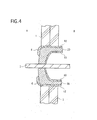
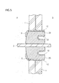
- FIGS.3 to 5 are a schematic cross-sectional view for explaining the fire resistance test using the structure for the pass-through section in the fire protection compartment of Example 1 according to the present invention.
- the fire resistance test compliant with ISO 834 was carried out from the A side described in FIGS. 3 to 5 (in FIG. 3 , from the left side).
- FIG. 3 Once the fire resistance test started, as exemplified n FIG. 3 , as the heat insulating material 4 included in structure for the pass-through section in the fire protection compartment of the Example 1 is molten and removed, expansion residues 20 of the thermally expandable fire-resistant sheet began to expand.
- the expansion residues 20 compresses as it comes in contact with the pipe or the like 3, and adheres to the pipe or the like 3. Furthermore, over time, as exemplified in FIG. 5 , the expansion residues 20 is being formed from the heated A side of the compartment to the un-heated B side of the compartment by the expanding pressure from the expansion residues so that the aluminum foil 10 is wrapped in.
- Example 2 is a modification of Example 1.
- Example 2 is similar to Example 1, provided that the thermally expandable fire-resistant sheet 50 is used instead of the thermally expandable fire-resistant sheet 5 used in Example 1, which the size of the sheet 50 is different from that of the sheet 5.
- FIG. 6 is a schematic cross-sectional view illustrating the structure for the pass-through section in the fire protection compartment of Example 2.
- Example 1 one end face of the thermally expandable fire-resistant sheet 5 and the outer surface of the cavity wall 1 are arranged in substantially identical plane (see FIG. 1 ).
- Example 2 the thermally expandable fire-resistant sheet 50 is installed so that 20mm of both end faces of the sheet 5 protrudes from the outer surface of the cavity wall 1.
- the seal member 6 as a noncombustible caulking is located on the circumference of the heat insulating material 4, the end face of the thermally expandable fire-resistant sheet 50, and the outer surface of the cavity wall 1.
- the seal member 6 is located so as to cover the pass-through hole 2.
- the fire resistance test compliant with ISO 834 was carried out with the structure for the pass-through section in the fire protection compartment of Example 2. The result was similar to that of Example 1.
- Example 3 is a modification of Example 1.
- FIG. 7 is a schematic cross-sectional view illustrating the structure for the pass-through section in the fire protection compartment of Example 3.
- Example 1 the heat insulating material 4 is winded by the thermally expandable fire-resistant sheet 5.
- Example 3 the size of the pass-through hole 2 formed in the cavity wall 1 is larger than that of Example 1. Therefore, Example 3 is similar to Example 1, provided that a seal member 6 as a noncombustible caulking is filled between the thermally expandable fire-resistant sheet 5 used in Example 1 and the pass-through hole 2.
- the fire resistance test compliant with ISO 834 was carried out with the structure for the pass-through section in the fire protection compartment of Example 3. The result was similar to that of Example 1.
- Example 4 is a modification of Example 2.
- FIG. 8 is a schematic cross-sectional view illustrating the structure for the pass-through section in the fire protection compartment of Example 4.
- the heat insulating material 4 is winded by the thermally expandable fire-resistant sheet 50.
- the size of the pass-through hole 2 formed in the cavity wall 1 is larger than that of Example 1. Therefore, Example 4 is similar to Example 2, provided that a seal member 6 as a noncombustible caulking is filled between the thermally expandable fire-resistant sheet 50 used in Example 1 and the pass-through hole 2.
- the fire resistance test compliant with ISO 834 was carried out with the structure for the pass-through section in the fire protection compartment of Example 4. The result was similar to that of Example 2.
- FIG. 9 is a schematic cross-sectional view illustrating expansion residues observed from non-heated side of the cavity wall in the fire resistance test of Comparative Example 1. When observed it from the un-heated side of the cavity wall 1, it was found that the expansion residues on the upper side of the pipe or the like 3 glows. When examined the structure for the pass-through section in the fire protection compartment of Comparative Example 1 after completion the test, it was found that the expansion residues on the side of the pipe or the like 3 was very fragile and had a low density.
- the fire resistance test compliant with ISO 834 was carried out with the structure for the pass-through section in the fire protection compartment of Example 1, provided that three layered the thermally expandable fire-resistant sheet of a non-woven fabric, an epoxy resin containing the thermally expandable resin composition 11 (available under trade name Fi-BlockTM from Sekisui Chemical Co Ltd.), and a non-woven fabric was used instead of the thermally expandable fire-resistant sheet 5.
- an epoxy resin containing the thermally expandable resin composition 11 available under trade name Fi-BlockTM from Sekisui Chemical Co Ltd.
- a non-woven fabric was used instead of the thermally expandable fire-resistant sheet 5.
- the present invention can widely apply to a structure r architecture, marine vessels or the like as a structure for a pass-through section in a fire protection compartment for providing in a partition section of the structure.
Landscapes
- Engineering & Computer Science (AREA)
- General Engineering & Computer Science (AREA)
- Mechanical Engineering (AREA)
- Ceramic Engineering (AREA)
- Chemical & Material Sciences (AREA)
- Textile Engineering (AREA)
- Building Environments (AREA)
Abstract
Description
- The present invention relates to a structure for a pass-through section in a fire protection compartment provided in a partition section of the structure for architecture, marine vessels or the like.
- A partition section of the structure for architecture r the like usually includes some compartments so that flame and smoke do not spread to the other side of the partition section, even if a fire breaks out at one side of the partition section of the structure for architecture or the like.
When a pipe or the like is installed in the structure, a pass-through hole is formed through the compartment, the pipe or the like needs to be inserted in the pass-through hole.
However, if the pipe or the like is merely inserted in the pass-through hole, there is an issue that flame and smoke diffuses from one side of the compartment to the other side by transferring through the pass-through hole at the time of fire occurrence. - A variety of structure has been proposed to address this issue. To protect the flame and smoke from diffusing the pass-through hole, a structure is proposed that a sheath tube, called as a sleeve, is disposed in the pass-through hole provided in the compartment, the pipe or the like is inserted in the sleeve, and that a thermally expandable fire-resistant sheet is adhered to inside of the sleeve so that the sheet is spaced from the pipe or the like (patent literature 1).
FIG. 10 is a schematic cross-sectional view illustrating the conventional structure for a pass-through section in a fire protection compartment.
Asleeve 110 is installed in a pass-through hole formed in acompartment 100 provided in a partition section of the structure for architecture. The gap between the pass-through hole and thesleeve 110 is filled withnoncombustible material 120 including mortar or the like. Further, a pipe or the like 130 is inserted in thesleeve 110.
Because both sides of thesleeve 100 are covered with aseal member 140, even if a fire occurs near the structure for the pass-through section in the fire protection compartment shown inFIG. 10 , smoke or the like cannot spread from one side of the compartment to the other side by passing through thesleeve 110. Also, because a thermally expandable fire-resistant sheet 150 is adhered to inside of thesleeve 110, and the sheet spaced from the pipe or the like, when the structure for the pass-through section in the fire protection compartment shown inFIG. 10 is exposed heat from the fire or the like, thermally expandable fire-resistant sheet 150 expands to seal inside thesleeve 110. Therefore, flame from the fire or the like cannot spread from one side of the compartment to the other side by passing through thesleeve 110.
The conventional structure for the pass-through section in the fire protection compartment includes thesleeve 110, so the pipe or the like 130 inserted in thesleeve 110 can be easily added, replaced, and removed. Additionally, if the conventional structure for a pass-through section in a fire protection compartment is exposed to heat from a fire, the thermally expandable fire-resistant sheet 150 adhered inside the sleeve is heated relatively uniformly via thesleeve 110, thereby the thermally expandable fire-resistant sheet 150 expands to seal the space inside thesleeve 110 as designed. Thus, in the conventional structure for the pass-through section in the fire protection compartment, the presence of the sleeve has an important meaning. -
- Patent Literature 1: Japanese Patent Laid-Open Publication No.
2006-29023 - However, it may be desired that the sleeve is not installed in some structure for architecture due to workability economic efficiency.
FIG. 11 is a schematic cross-sectional view illustrating the conventional structure for a pass-through section in a fire protection compartment shown inFIG. 10 without having a sleeve.
In the structure for the pass-through section in the fire protection compartment shown inFIG. 11 , any sleeve is not used. In the case of previousFIG. 10 , the thermally expandable fire-resistant sheet is adhered to inside of the sleeve, while in the case ofFIG. 11 , a thermally expandable fire-resistant sheet 150 is adhered to inside of the pass-through section by usingnoncombustible fixing material 120.
In the structure for the pass-through section in the fire protection compartment shown inFIG. 11 , if the structure is exposed to heat from a fire or the like, it is expected that the thermally expandable fire-resistant sheet 150 expands to seal the gap between the pass-through hole and the pipe or the like 130, which is similar to the structure for the pass-through section in the fire protection compartment having a sleeve as illustrated byFIG. 10 . - However, inventors of the present invention carried out an investigation to find that when the structure for the pass-through section in the fire protection compartment without having a sleeve shown in
FIG. 11 is exposed to heat from fire or the like, the thermally expandable fire-resistant sheet 150 expands but it does not adhere to pipe or the like 130 tightly, and then the expansion residues glows and cannot seal the pipe or the like adequately, thereby a gap can form between the expansion residues and the pipe or the like.
If the expansion residues does not seal around pipe or the like 130 adequately, and a gap forms between the expansion residues and the pipe or the like 130, then smoke and gases can diffuse from one side of the compartment where a fire occurs to the other side, or fire can spread. - It is an object of the present invention to provide a structure for a pass-through section in a fire protection compartment, the structure possessing superior sealing characteristics and superior fire resistance properties between expansion residues of the thermally expandable fire-resistant sheet subsequent to exposure to heat from a or the like and pipe or the like therein, even in cases wherein a sleeve is not used.
- Inventors of the present invention carried out an extensive investigation to solve the issue, among the structure for the pass-through section in the fire protection compartment, the inventors find that the structure for the pass-through section in the fire protection compartment used a thermally expandable fire-resistant sheet which is at least provided with a metal foil layer, a thermally expandable resin layer, and an inorganic fiber layer from the side of the heat insulating material meets an object of the present invention, and as a result, this invention could be accomplished.
- Accordingly, the present invention provides:
- [1] a structure for a pass-through section in a fire protection compartment, comprising:
- a pipe or the like inserted into a compartment pass-through hole provided in a partition section of the structure;
- a heat insulating material disposed around the pipe or the like; and
- a thermally expandable fire-resistant sheet installed between the pass-through hole and the heat insulating material;
- wherein the gap between the pass-through hole and the pipe or the like is either sealed with the heat insulating and the thermally expandable fire-resistant sheet, or is instead sealed with heat insulating material, the thermally expandable fire-resistant sheet, and a seal member,
- wherein the thermally expandable fire-resistant sheet is at least provided with a metal foil layer, a thermally expandable resin layer, and an inorganic fiber layer from the side of the heat insulating material.
- The present invention also provides:
- [2] the structure for the pass-through section in the fire protection compartment described above in [1],
wherein the thermally expandable fire-resistant sheet comprises at least the metal foil layer, an epoxy resin containing the thermally expandable resin layer, an inorganic fiber layer laminated with metal foil,
wherein the thickness of the metal foil layer is from 7 to 30 µm. - Further, the present invention provides:
- [3] the structure for the pass-through section in the fire protection compartment of [1] or [2],
wherein the pass-through hole is covered with the seal member which is installed so as to contact with around the heat insulating material and the end face of the thermally fire-resistant sheet. - Additionally, the present invention provides:
- [4] a method for controlling an expansion of a thermally expandable fire-resistant sheet,
wherein the thermally expandable fire-resistant sheet comprises at least the metal foil layer, a thermally expandable resin layer, and an inorganic fiber layer,
wherein the thermally expandable fire-resistant sheet expands from the heated side of the compartment to the other side of the compartment so that the metal foil layer is wrapped in when the heat insulating material in one compartment of the structure for the pass-through section in the fire protection compartment of any one of [1] to [3] is burned down or molten, and the thermally expandable fire-resistant sheet is heated above the temperature which the sheet begins to expand. - Because the structure for the pass-through section in the fire protection compartment of the present invention uses a thermally expandable fire-resistant sheet which is at least provided with a metal foil layer, a thermally expandable resin layer, and an inorganic fiber layer from the side of the heat insulating material, if the structure for the pass-through section in the fire protection compartment is heated from one side of the compartment, then the thermally expandable resin layer expands from one side of the compartment heated to the other side while enfolding the metal foil layer inside due to tensile force of the outermost surface of the metal foil layer.
In the case, the thermally expandable resin layer not only expands toward the center of the pass-through hole, but also expands in a direction perpendicular to the compartment.
Accordingly, compared to the conventional structure fo a pass-through section in a fire protection compartment which only expands toward the center of the pass-through hole of the compartment, provided is a structure for a pass-through section in a fire protection compartment, the structure possessing superior sealing characteristics and superior fire resistance properties between expansion residues of the thermally expandable fire-resistant sheet subsequent to exposure to heat from a fire or the like and a pipe or the like therein. - When the thickness of the metal foil layer used in the present invention is in a range from 7 to 30µm, the structure for a pass-through section in the fire protection compartment is exposed to heat from one side of the compartment, the thermally expandable resin layer expands from one side of the compartment heated to the other side while enfolding the metal foil layer inside smoothly. Therefore, provided is a for a pass-through section in a fire protection compartment, the structure possessing superior sealing characteristics and superior fire resistance properties between expansion of the thermally expandable fire-resistant sheet subsequent to exposure to heat from a fire or the like and a pipe or the like therein.
- The structure for the pass-through section in the fire protection compartment of the present invention can protect smoke and toxic gases generating at one side of the compartment from spreading from the one side to the other side, because the pass-through hole is covered with the seal member which is installed so as to contact with around the heat insulating material and the end face of the thermally expandable fire-resistant sheet.
- An expansion of a thermally expandable fire-resistant sheet can be controlled by using a thermally expandable fire-resistant sheet comprises at least the metal foil layer, a thermally expandable resin layer, and an inorganic fiber layer from the side of the heat insulating material to a structure for a pass-through section in a fire protection compartment, if the structure for the pass-through section in the fire protection compartment is heated from one side of the compartment, then the thermally expandable resin layer expands from one side of the compartment heated to the other side while enfolding the metal foil layer inside.
-
-
FIG. 1 is a schematic cross-sectional view illustrating the structure for the pass-through section in the fire protection compartment of Example 1 according to the present invention; -
FIG. 2 is a schematic cross-sectional view illustrating the thermally expandable fire-resistant sheet used in Example 1 according to the present invention; -
FIG. 3 is a schematic cross-sectional view illustrating the fire resistance test with the structure for the pass-through section in the fire protection compartment of Example according to the present invention; -
FIG. 4 is a schematic cross-sectional view illustrating the fire resistance test with the structure for the pass-through section in the fire protection compartment of Example according to the present invention; -
FIG. 5 is a schematic cross-sectional view illustrating the fire resistance test with the structure for the pass-through section in the fire protection compartment of Example 1 according to the present invention; -
FIG. 6 is a schematic cross-sectional view illustrating the structure for the pass-through section in the fire protection compartment of Example 2; -
FIG. 7 is a schematic cross-sectional view illustrating the structure for the pass-through section in the fire protection compartment of Example 3; -
FIG. 8 is a schematic cross-sectional view illustrating the structure for the pass-through section in the fire protection compartment of Example 4; -
FIG. 9 is a schematic cross-sectional view illustrating expansion residues observed from non-heated side of the cavity wall in the fire resistance test of Comparative Example 1;FIG. 10 is a schematic cross-sectional view illustrating the conventional structure for a pass-through section in a fire protection compartment; and -
FIG. 11 is a schematic cross-sectional view illustrating the conventional structure for a pass-through section in a fire protection compartment. - While the present invention relates to a structure for a pass-through section in a fire protection compartment, firstly described is a pipe or the like used the present invention.
The pipe or the like is inserted the pass-through hole of the compartment provided in a partition section of the structure for architecture, marine vessels or the like. - Example of the pipe or the like include pipes for transporting liquids, such as a refrigerant pipe, a pipe for heat medium, a water pipe, a sewage pipe, a pipe for injecting or draining water, a fuel transfer pipe, a hydraulic piping; pipes for transporting gases, such as a gas pipe, a pipe for transporting heating or cooling medium, a vent pipe; cables, such as an electric wire and cable, an optical-fiber cable, a cable for marine vessels.
Among them, in terms of workability, pipes for transporting liquids is preferable, including a refrigerant pipe, a water pipe, a sewage pipe, a pipe for injecting or draining water, a fuel transfer pipe, hydraulic piping, more preferably a refrigerant pipe. - The pipe or the like can be used one of the pipes for transporting liquids, pipes for transporting gases, cables, or two or more thereof.
- The shape of the pipe or the like is not particularly limited, and examples of the pipe or the like include those having a cross-sectional shape of polygonal, such as triangular, quadrangular; those having a cross-sectional shape with two different sides, such as rectangle; those having a cross-sectional shape with two different interior angles, such as parallelogram; those having a cross-sectional shape of oval, round shape, wherein the cross-sectional shape is in a perpendicular to the longitudinal direction of the pipe or the like. Among them, those having a cross-sectional shape of round shape or quadrangular is preferable because they have improved workability.
- The cross-sectional size of the pipe or the like is usually in a range from 1 to 1000 mm, preferably in a range from 5 to 750 mm based on the longest length between the center of gravity of the cross-sectional shape and the outer line of the cross-sectional shape. When the pipe or the like is pipes for transporting liquids, pipes for transporting gases, cables or the like, the size is usually in a range from 0.5 mm to 10 cm, preferably in a range from 1 mm to 5 cm.
- While the material for the pipe or the like is not particularly limited, and examples thereof include one of metallic material, inorganic material, organic material, and two or more combinations thereof.
Examples of the metallic material include iron, steel, stainless steel, copper, and the alloy of two or more thereof. - In addition, examples of inorganic material include glass, ceramics. Examples of organic material include synthetic resins, such as vinyl chloride resin, ABS resin, vinylidene fluoride resin, polyethylene resin, polypropylene resin. One, two or more these materials can be used.
- While the pipe or the like used in the present invention is at least one of metallic material pipes, inorganic material pipes, and organic material pipes, it can be used as a laminated pipe using two or more of metallic material pipes, inorganic material pipes, and organic material pipes as inner pipe or outer pipe.
In terms of handling, the pipe or the like is preferably metallic material pipes, organic material pipes, or the like. More preferably, the pipe or the like is metallic material pipes, such as steel pipes, copper pipes. - The pipe or the like used in the present invention is inserted in the pass-through hole of the compartment provided the partition section of the structure. Examples of the compartment include a wall of structure for architecture, a partition, a floor, a ceiling, a steel plate disposed waterproof compartment for marine vessels or cabins. The pipe or the like can be inserted in the pass-through hole by providing the pass-through hole in the compartment.
- Next, described in a thermally expandable fire-resistant sheet used in the present invention. The thermally expandable fire-resistant sheet used in the present invention comprises at least a metal foil layer, a thermally expandable resin layer, and an inorganic fiber layer.
Example of the metal foil used in the metal foil layer include aluminum foil, copper foil, stainless steel foil, foil, lead foil, tin-lead alloy foil, clad foil, lead antifoil. In terms of workability, the metal foil is preferably foil, copper foil or the like. - The thickness of the metal foil layer is preferably in a range from 7 to 30µm, more preferably in range from to 20µm. When the thickness of the metal foil layer is less than 7µm, the tensile force of the metal foil is unsatisfactory, while when the thickness of the metal foil layer is over 30µm, the layer has a poor flexibility. In these cases, if one compartment of the structure for the pass-through section in the fire protection compartment of the present invention is exposed to heat from a fire, then the thermally expandable fire-resistant sheet can be avoided expanding from one side the compartment heated to the other side while enfolding the metal foil layer inside smoothly.
- Examples of the thermally expandable resin composition used in the thermally expandable resin layer include an epoxy resin containing the thermally expandable resin composition containing an epoxy resin as a resin component, and a compound, a thermally expandable layered inorganic, an inorganic filler.
- The resin component is not particularly limited, and examples thereof include resins resulted from the reaction of a monomer having an epoxy group and a curing agent.
- Examples of the monomer having an epoxy group include, as two functional glycidyl ether based monomer, polyethylene glycol based monomer, polypropyleneglycol based monomer, neopentylglycol based monomer, 1,6-hexanediol based monomer, trimethylolpropane based monomer, propyleneoxide-bisphenol A, hydrogenerated bisphenol A based monomer, bisphenol A based monomer, bisphenol F based monomer.
- Also, examples of glycidyl ester based monomer include hexahydrophthalic anhydride based monomer, tetrahydro phthalic anhydride based monomer, dimer acid based monomer, p-oxyoxybenzoic acid based monomer.
- Examples of the multifunctional glycidyl ether based monomer include phenol-novolac based monomer, orthocresol based monomer, DPP-novolac based monomer, dicyclopentadienes, phenol based monomer.
- One, two or more of these monomers can be used.
- Further, examples of the curing agent include curing agents for polyaddition, curing agents for catalysis. Examples of the polyaddition typecuring agent include polyamines, acid anhydrides, polyphenols, polymercaptans.
- Examples of the curing agent for catalysis include tertiary amines, imidazoles, Lewis acid complexes. A for curing these epoxy resins is not particularly limited, and can be performed according to any known methods in the art.
- Blends of above two or more resin components can be used to adjust melting viscosity, flexibility, and adherence property of the resin components.
- The phosphorus compound is not particularly limited, and examples thereof include red phosphorus; various phosphate esters, such as triphenylphosphate, tricresyl phosphate, trixylenyl phosphate, cresyldiphenylphosphate, xylenyldiphenylphosphate; metallic phosphates, such as sodium phosphate, potassium phosphate, magnesium phosphate; ammonium polyphosphates; compounds represented by
chemical formula 1. - One, two or more of these phosphorus compounds can be used.
- Among them, in terms of fire resistance properties, re phosphorus, compounds represented by the following chemical formula, ammonium polyphosphates are preferred, in terms of performance, safety, cost, ammonium polyphosphates are more preferred.
-

- R2 represents a hydroxyl group, a linear or branched alkyl group having 1 to 16 carbon atoms, a linear or branched alkoxyl group having 1 to 16 carbon atoms, an aryl group having 6 to 16 carbon atoms, or aryloxy group having 6 to 16 carbon atoms.
- The compounds represented by the chemical formula includes methylphosphonic acid, dimethyl methylphosphonate, diethyl methylphosphonate, ethylphosphonic acid, propylphosphonic acid, butylphosphonic acid, 2-methylpropylphosphonic acid, t-butylphosphonic acid, 2,3-dimethyl-butylphosphonic acid, octylphosphonic acid, phenylphosphonic acid, dioctylphenyl phosphonate, dimethylphosphinic acid, methylethylphosphinic acid, methylpropylphosphinic acid, diethyl phosphinic acid, dioctylphosphinic acid, phenylphosphinic acid, diethyl phenylphosphinic acid, diphenylphosphinic acid, bis(4-methoxyphenyl)phosphinic acid.
- Among them, t-butylphosphonic acid, which is expensive, is preferable in terms of high fire resistance.
- Ammonium polyphosphates are not particularly limited, and examples thereof include ammonium polyphosphate, melamine modified ammonium polyphosphate or the like. In terms of fire resistance, safety, cost, handling property, ammonium polyphosphate is suitably used.
- Commercially available products include trade name EXOLIT AP422 and EXOLIT AP462 manufactured by Clariant.
- The phosphorus compound appears to react with a metallic carbonate such as calcium carbonate, zinc carbonate to promote the expansion of the metallic carbonate. In particular, when ammonium polyphosphate is used as the phosphorus compound, it offers great expansion effect. Additionally, it acts efficient aggregate, after burning, it forms a residue having high shape retention.
- Next, among each components in the thermally expandable resin composition, described is a thermally expandable layered inorganic. The thermally expandable layered inorganic expands during heating, such the thermally expandable layered inorganic is not particularly limited, and examples thereof include vermiculite, kaolin, mica, the thermally expandable graphite.
- The thermally expandable graphite is conventionally known materials in the art. The thermally expandable graphite is produced by treating powdery graphite such as natural flake graphite, pyrolytic graphite, kish graphite with inorganic acid such as concentrated sulfuric acid, nitric acid, selenic acid and strong oxidizing agent such as concentrated nitric acid, perchloric acid, hyperchloride, permanganate, dichromate, dichromate, hydrogen peroxide to form a graphite intercalation compound, which is one of crystalline compounds having layered structure of carbon.
- The thermally expandable graphite obtained by treating with acids as described above is preferably used by further neutralizing with ammonia, aliphatic lower amine, alkali metal compounds, alkaline earth metal compounds.
- Examples of the aliphatic lower amine include monomethylamine, dimethylamine, trimethylamine, ethylamine, propylamine, butylamine.
- Examples of the alkali metal compound and the alkaline earth metal compound include hydroxides, oxides, carbonates, sulfates, organic acid salts of potassium, sodium, calcium, barium, magnesium and the like.
- The particle size of the thermally expandable graphite is preferably in a range from 20 to 200 meshes.
When the particle size is less than 20 meshes, the degree of expansion of the graphite decreases, and the heat insulating layer having an inadequate resistance to fire property can be obtained. On the other hand, when the particle size is more than 200 meshes, there is an advantage that the degree of expansion of the graphite increases, but it has a poor dispersibility during kneading with the rmoplastic resin or epoxy resin, and tends to decrease its properties. - Examples of commercially available neutralized the thermally expandable graphite as described above include GRAFGUARD#160, GRAFGUARD#220 from UCAR Carbon Co., Inc., and GREP-EG from Tosoh corporation.
- Next, among of the each components of the thermally expandable resin composition, an inorganic filler is described. The inorganic filler is not particularly limited, and thereof include silica, diatomite, alumina, zinc oxide, titanium oxide, calcium oxide, magnesium oxide, iron oxide, tin oxide, antimony oxide, ferrites, calcium hydroxide, magnesium hydroxide, aluminum hydroxide, basic magnesium carbonate, calcium carbonate, magnesium carbonate, zinc carbonate, barium carbonate, dawsonite, hydrotalcite, calcium sulfate, barium sulfate, satin spar, potassium salts of calcium silicate or the like, talc, clay, mica, montmorillonite, bentonite, activated clay, sepiolite, imogolite, sericite, glass fibers, glass beads, silica balloons, aluminum nitride, boron nitride, silicon nitride, carbon black, graphite, carbon fibers, carbon balloons, charcoal powder, various metal powders, potassium titanate, magnesium sulfate, lead zirconate titanate, aluminum borate, molybdenum sulfide, silicon carbide, stainless steel fibers, zinc borate, various magnetic powders, slag fibers, fly ash, inorganic phosphorus compounds, silica alumina fibers, alumina fibers, silica fibers, zirconia fibers.
- One, two or more inorganic fillers can be used.
- The inorganic filler acts as a aggregate. The inorganic filler contributes to an improved strength and heat capacity of the expanded heat insulating layer produced after heating.
- Therefore, metallic carbonates, which the representative examples are calcium carbonate, zinc carbonate; aqueous inorganics, which the representative examples are aluminum hydroxide and magnesium hydroxide which acts as an aggregate and has endothermic effect after heating is preferred. A mixture of metallic carbonate of alkali metal, alkaline earth metal and metallic carbonate of IIb element in The Periodic Table, or a mixture of these carbonates and the aqueous inorganics is preferred.
- When the inorganic filler used in the present inventio is particle, the size is preferably in a range from 0.5 to 200µm, more preferably in a range from 1 to 50µm.
- When the added amount of the inorganic filler is lower, the filler has preferably smaller particle size because the dispersibility of the filler has a great influence on properties. However, when the particle size of the inorganic filler is less than 0.5µm, the filler may form the secondary aggregates, and degrade the dispersibility.
- Additionally, when the added amount of the inorganic filler is high, the viscosity of the resin composition increases, and thus the moldability of the composition decreases the filling thereof proceeds. Because the viscosity of the resin composition can decrease by increasing its particle size, larger one within these range is preferred.
- Moreover, when the particle size is over 200µm, surface property of the molded products and mechanical properties of the resin composition may be degraded.
- Among the inorganic filler, in particular, metallic carbonates such as calcium carbonate, zinc carbonate which acts as an aggregate; aqueous inorganic such as aluminum hydroxide and magnesium hydroxide which has endothermic effect during heating and acts as an aggregate is preferred.
- The combination of the aqueous inorganic and the metallic carbonates appears to highly contribute to an improved strength and heat capacity of the burned residue.
- Among the inorganic filler, the aqueous inorganic such as aluminum hydroxide, magnesium hydroxide is particularly preferred in that endothermic reaction occurs by water generated from dehydration reaction during heating, and thus rise in temperature decreases to improve heat resistance, and that the strength of the combustion residue improves by remaining oxides as combustion residue to act as a aggregate.
- Further, magnesium hydroxide and aluminum hydroxide exert dehydration effect at different range of temperature, so the range of temperature exerting dehydration effect broadens by using a combination of magnesium hydroxide and aluminum hydroxide.
Additionally, the combination offers more efficient in limiting the rise in temperature. Therefore, the combination is preferred. - When the particle size of the aqueous inorganic decreases, it becomes too bulky to fill highly. Therefore, preferred is the aqueous inorganic having larger particle size to fill highly for improving dehydration effect. Specifically, it is known that using the aqueous inorganic having a particle size of 18µm, limit of filling is about one and a half time over that of 1.5µm. Additionally, the particle can fill highly by combinating larger particle and smaller particle.
- Commercially available products of aqueous inorganic include aluminum hydroxide sold under trade name HIGILITETM H-42M having a particle size of 1µm (manufactured by Showa Denko K.K.), and trade name HIGILITETM H-31 having a particle size of 18µm (manufactured by Showa Denko K.K.).
- Commercially available products of the calcium carbonate include that sold under trade name WHITON SB Red having a particle size of 1.8µm (manufactured by SHIRAISHI CALCIUM KAISHA, LTD.), and trade name BF300 having a particle of 8µm (manufactured by Bihoku Funka Kogyo Co.,Ltd.).
- As mentioned in the beginning, examples of the thermally expandable fire-resistant material used in the present invention include those containing the resin component, such as epoxy resin as described above, the thermally expandable layered inorganic, and the inorganic filler. Now their formulation will be described.
- The resin composition preferably contains 20 to 350 weight parts of the thermally expandable layered inorganic, 50 to 400 weight parts of the inorganic filler based on 100 weight parts of the resin components of the epoxy resin. Further, the sum of the thermally expandable layered inorganic and inorganic filler is preferably in a range from 200 to 600 weight parts.
- By heating, the resin composition expands to form the fire-resistant insulating fire layer. According to the formulation, the thermally expandable fire-resistant material can expand subsequent to exposure to heat from a fire or the like to accomplish necessary volume expansion. After expansion, the material can form residues having a determined heat insulating property and strength, resulting in a fireproof performance.
- When the amount of the layered inorganic is less than 20 weight parts, the expansion ratio is too small to provide a sufficient fire resistance properties and fire preventing properties. On the other hand, when the amount of the layered inorganic is over 350 weight parts, cohesive force is too small to provide a good strength as a molded article. When amount of the inorganic filler is less than 50 weight parts, remaining volume the filler after combustion can decrease, and then insufficient heat insulating fire layer can occur. Additionally, as the ratio of combustible material increases, flame resistance may decrease.
- On the other hand, if the amount of the inorganic filler is over 400 weight parts, the ratio of resin component formulated decreases, and cohesive force is too small to provide a good strength as a molded article.
- When the sum of the thermally expandable layered inorganic and the inorganic filler in the resin composition is less than 200 weight parts, the amount of the residues after burning is lacking, resulting in insufficient fire resistance properties. On the other hand, when the sum is over 600 weight parts, decrease in mechanical property may be too high to use.
- The thermally expandable resin composition used in the present invention may further contain any additive, such as an agents for inhibiting harm of metals, an antistatic agent, a stabilizing agent, a cross-linking agent, a lubricant, a flexibilizer, a pigment, a tackifier resin, and tackifier, such as polybutene, petroleum resin, in addition to an antioxidant such as phenols, amines, sulphurs as necessary, as long as the object of the present invention does not fail.
- Next, described is a method for producing a thermally expandable resin composition. The method for producing the thermally expandable resin composition is not particularly limited, and the composition can be obtained by a method which the thermally expandable resin composition is dispersed in organic solvent, or heated and molten to form a coating, a method which the composition is dispersed in solvent to prepare a slurry, a method which the composition is molten under heating.
- The thermally expandable resin composition can be obtained by kneading these components using any known apparatus including a single screw extruder, a twin screw extruder, a Bumbary mixer, a kneader mixer, a kneading roll, a Raikai mixer, a planetary gearbox mixer.
- Also, filler is kneaded with monomer having an epoxy group, and kneaded with curing agent separately, and then their mixture can knead with static mixer, dynamic mixer immediately before molding.
- The thermally expandable resin composition used in the present invention can be obtained by the method as described above.
- Described herein is an inorganic fiber layer, which is included in the thermally expandable fire-resistant sheet, used in the present invention.
Examples of an inorganic fiber used in the inorganic fiber layer include glass wool, rock wool, ceramic wool, satin spar, carbon fibers, stainless steel fibers, slag fibers, silica alumina fibers, alumina fibers, silica fibers, zirconia fibers. The inorganic fiber layer is preferably used inorganic fiber cloth using the inorganic fiber.
In addition, the inorganic fiber layer used in the inorganic fiber layer is preferably used by laminating metal foil.
More preferred specific examples of the inorganic fiber laminated with metal foil include aluminum foil laminated glass cloth, copper foil laminated glass cloth. - The thermally expandable fire-resistant sheet used in the present invention can be obtained by laminating a metal foil layer, a thermally expandable resin layer, and an inorganic fiber layer or the like. The lamination includes co-extrusion molding, hot press, and the like, and means for sticking each layer with adhesive agent. It is preferred that the metal foil layer is in the outermost surface of the thermally expandable fire-resistant sheet used in the present invention.
- Next, a heat insulating material used in the present invention is described.
As the heat insulating material, synthetic resins having air bubbles therein are used including urethane foam, polyethylene foam, polypropylene foam, vinyl chloride foam, polystyrene foam.
The synthetic resins having air bubbles therein is preferred, because the synthetic resins having air bubbles therein is molten or burned down subsequent to exposure to heat from a fire or the like, and do not disturb a expansion of the thermally expandable fire-resistant sheet. - In addition, examples of the seal member used in the present invention include sealant for architecture specified under JIS A5758, epoxy injection sealant for repairing in buildings specified under JIS A6024, jointing materials for gypsum plasterboards specified under JIS A6914, mortar, putty, and caulking. As the
seal member 4, in terms of workability, putty and caulking made of rubber such as chloroprene
or silicone formulated with filler, fire retardant is preferred. - Next, while several examples of the invention are now described in further detail with reference to Figures, the present invention is not limited in any ways by these examples. Examples
-
FIG. 1 is a schematic cross-sectional view illustrating the structure for the pass-through section in the fire protection compartment of Example 1 according to the present invention.
In Example 1, acavity wall 1 of the structure is used as a compartment provided in a partition section of the structure.
The cavity wall inFIG. 1 is formed by arranging a pai of spaced two plasterboards.
Thecavity wall 1 includes a circular pass-throughhole 2, a pipe or the like 3 (copper pipe) is inserted in the pass-throughhole 2.
The pipe or the like 3 used in the Example had an outer diameter of 25 mm. - Additionally, urethane foam as a
heat insulating material 4 is sealed tightly on the circumference of the pipe or the like 3. Theheat insulating material 4 had a thickness of The thickness of the heat insulating material used in the present invention is preferably in a range from 25 mm to 65 mm.
Further, a thermally expandable fire-resistant sheet 5 is installed in a gap between theheat insulating material 4 and the pass-through hole so that theheat insulating material 4 is winded by the thermally expandable fire-resistant sheet 5. The width of the thermally expandable fire-resistant sheet 5 is preferably within a range from 100 to 300 percent based on that of theheat insulating material 4 in a perpendicular direction to the surface of thecavity wall 1.
The thermally expandable fire-resistant sheet 5 is installed so that 20mm of thesheet 5 protrudes in thecavity wall 1.
The gap between the pipe or the like 3 and the pass-throughhole 2 is sealed tightly with theheat insulating material 4 and the thermally expandable fire-resistant sheet 5. - Additionally, a
seal member 6 as a noncombustible caulking is located on the circumference of theheat insulating material 4 and the end face of the thermally expandable fire-resistant sheet 5. Theseal member 6 is located so as to cover the pass-throughhole 2. -
FIG. 2 is a schematic cross-sectional view illustrating the thermally expandable fire-resistant sheet used in Example 1 of the present invention.
As shown inFIG. 2 , theheat insulating material 4 is winded by the thermally expandable fire-resistant sheet 5, and inserted in the pass-throughhole 2 of thecavity wall 1. - The thermally expandable fire-
resistant sheet 5 is produced by laminating in order of analuminum foil 10, an epoxy resin containing the thermally expandable resin composition 11 (available under trade name Fi-Block™ from Sekisui Chemical Co Ltd.), an aluminum foil laminatedglass cloth 12 from theheat insulating material 4.
Thealuminum foil 10 has a thickness of 20µm. In this case, the epoxy resin containing the thermally expandableresin composition layer 11 is used by piling three sheets having a thickness of 1mm. - In
FIG. 1 and FIG. 2 , the pass-throughhole 2 formed in thecavity wall 1 is filled tightly with the pipe or the like 3, theheat insulating material 4 and the thermally expandable fire-resistant sheet 5.
Therefore, the shape of the pass-throughhole 2 along the surface of thecavity wall 1 is homologous of that of the cross-section of the pipe or the like 3, theheat insulating material 4, and the thermally expandable fire-resistant sheet 5 along the surface of thecavity wall 1. -
FIGS.3 to 5 are a schematic cross-sectional view for explaining the fire resistance test using the structure for the pass-through section in the fire protection compartment of Example 1 according to the present invention.
The fire resistance test compliant with ISO 834 was carried out from the A side described inFIGS. 3 to 5 (inFIG. 3 , from the left side).
Once the fire resistance test started, as exemplified nFIG. 3 , as theheat insulating material 4 included in structure for the pass-through section in the fire protection compartment of the Example 1 is molten and removed,expansion residues 20 of the thermally expandable fire-resistant sheet began to expand. - As exemplified in
FIG. 4 , once thealuminum foil 10 comes in contact with the pipe or the like 3, the aluminum foil intercepts the expanding pressure from theexpansion residues 20. Therefore, theexpansion residues 20 compresses as it comes in contact with the pipe or the like 3, and adheres to the pipe or the like 3.
Furthermore, over time, as exemplified inFIG. 5 , theexpansion residues 20 is being formed from the heated A side of the compartment to the un-heated B side of the compartment by the expanding pressure from the expansion residues so that thealuminum foil 10 is wrapped in. - When observed the structure for the pass-through section in the fire protection compartment from the B side described in
FIG. 5 , glowing of theexpansion residues 20 could be observed before and after the fire resistance test.
In addition, the temperature of the un-heated side of theheat insulating material 4 increased to 111 ?C at 2 hours after starting of the fire resistance test, and the leakage flame could not observed at the B side of the structure for pass-through section in the fire protection compartment. - Example 2 is similar to Example 1, provided that the thermally expandable fire-
resistant sheet 50 is used instead of the thermally expandable fire-resistant sheet 5 used in Example 1, which the size of thesheet 50 is different from that of thesheet 5. -
FIG. 6 is a schematic cross-sectional view illustrating the structure for the pass-through section in the fire protection compartment of Example 2.
In Example 1, one end face of the thermally expandable fire-resistant sheet 5 and the outer surface of thecavity wall 1 are arranged in substantially identical plane (seeFIG. 1 ).
Unlike Example 1, in Example 2, the thermally expandable fire-resistant sheet 50 is installed so that 20mm of both end faces of thesheet 5 protrudes from the outer surface of thecavity wall 1. - Also, the
seal member 6 as a noncombustible caulking is located on the circumference of theheat insulating material 4, the end face of the thermally expandable fire-resistant sheet 50, and the outer surface of thecavity wall 1. Theseal member 6 is located so as to cover the pass-throughhole 2.
The fire resistance test compliant with ISO 834 was carried out with the structure for the pass-through section in the fire protection compartment of Example 2. The result was similar to that of Example 1. -
FIG. 7 is a schematic cross-sectional view illustrating the structure for the pass-through section in the fire protection compartment of Example 3.
In Example 1, theheat insulating material 4 is winded by the thermally expandable fire-resistant sheet 5. On the other hand, in Example 3, the size of the pass-throughhole 2 formed in thecavity wall 1 is larger than that of Example 1. Therefore, Example 3 is similar to Example 1, provided that aseal member 6 as a noncombustible caulking is filled between the thermally expandable fire-resistant sheet 5 used in Example 1 and the pass-throughhole 2.
The fire resistance test compliant with ISO 834 was carried out with the structure for the pass-through section in the fire protection compartment of Example 3. The result was similar to that of Example 1. -
FIG. 8 is a schematic cross-sectional view illustrating the structure for the pass-through section in the fire protection compartment of Example 4.
In Example 2, theheat insulating material 4 is winded by the thermally expandable fire-resistant sheet 50. On the other hand, in Example 4, the size of the pass-throughhole 2 formed in thecavity wall 1 is larger than that of Example 1. Therefore, Example 4 is similar to Example 2, provided that aseal member 6 as a noncombustible caulking is filled between the thermally expandable fire-resistant sheet 50 used in Example 1 and the pass-throughhole 2.
The fire resistance test compliant with ISO 834 was carried out with the structure for the pass-through section in the fire protection compartment of Example 4. The result was similar to that of Example 2. - The fire resistance test compliant with ISO 834 was carried out with the structure for the pass-through section in the fire protection compartment of Example 1 without containing
aluminum foil 10 of the thermally expandable fire-resistant sheet 5.
FIG. 9 is a schematic cross-sectional view illustrating expansion residues observed from non-heated side of the cavity wall in the fire resistance test of Comparative Example 1.
When observed it from the un-heated side of thecavity wall 1, it was found that the expansion residues on the upper side of the pipe or the like 3 glows. When examined the structure for the pass-through section in the fire protection compartment of Comparative Example 1 after completion the test, it was found that the expansion residues on the side of the pipe or the like 3 was very fragile and had a low density. - The fire resistance test compliant with ISO 834 was carried out with the structure for the pass-through section in the fire protection compartment of Example 1, provided that three layered the thermally expandable fire-resistant sheet of a non-woven fabric, an epoxy resin containing the thermally expandable resin composition 11 (available under trade name Fi-BlockTM from Sekisui Chemical Co Ltd.), and a non-woven fabric was used instead of the thermally expandable fire-
resistant sheet 5.
As a result, it was found that the expansion residues n the upper side of the pipe or the like 3 glows as similar to Comparative Example 2 (SeeFIG. 9 ). When examined the structure for the pass-through section in the fire protection compartment of Comparative Example 2 after completion of the test, it was found that the expansion residues on the upper side of the pipe or the like 3 was very fragile and had a low density. - This application is based on Japanese Patent Application No.
2009-254948, filed on November 6, 2009 - The present invention can widely apply to a structure r architecture, marine vessels or the like as a structure for a pass-through section in a fire protection compartment for providing in a partition section of the structure.
-
- 1: cavity wall
- 2: pass-through hole
- 3: pipe or the like
- 4: heat insulating material
- 5, 50, 150: the thermally expandable fire-resistant sheet
- 6: seal member
- 10: aluminum foil
- 11: epoxy resin containing the thermally expandable resin composition
- 12: aluminum foil laminated glass cloth
- 20: expansion residues
- 100: compartment
- 110: sleeve
- 120: noncombustible fixing material
- 130: pipe or the like
- 140:seal member
- A: heated side where the fire resistance test carried out
- B: un-heated side of fire resistance test
Claims (6)
- A structure for a pass-through section in a fire protection compartment, comprising:a pipe or the like inserted into a compartment pass-through hole provided in a partition section of the structure;a heat insulating material disposed around the pipe or the like; anda thermally expandable fire-resistant sheet installed between the pass-through hole and the heat insulating material;wherein the gap between the pass-through hole and the pipe or the like is either sealed with the heat insulating material and the thermally expandable fire-resistant sheet, or is instead sealed with heat insulating material, the thermally expandable fire-resistant sheet, and a seal member,wherein the thermally expandable fire-resistant sheet is at least provided with a metal foil layer, a thermally expandable resin layer, and an inorganic fiber layer from the side of the heat insulating material.
- The structure for the pass-through section in the fire protection compartment according to claim 1, wherein the thermally expandable fire-resistant sheet comprises at least the metal foil layer, an epoxy resin containing the thermally expandable resin layer, an inorganic fiber layer laminated with metal foil, wherein the thickness of the metal foil layer is from 7 to 30 µm.
- The structure for the pass-through section in the fire protection compartment according to claim 2, wherein the seal member is located on the circumference of the heat insulating material and the end face of the thermally expandable fire-resistant sheet, wherein the seal member is located so as to cover the pass-through hole.
- A method for controlling an expansion of a thermally expandable fire-resistant sheet, wherein the thermally expandable fire-resistant sheet comprises at least the metal foil layer, a thermally expandable resin layer, and an inorganic fiber layer, wherein the thermally expandable fire-resistant sheet expands from the heated side of the compartment the other side of the compartment so that the metal foil layer is wrapped in when the heat insulating material in one compartment of the structure for the pass-through section in the fire protection compartment of claim 1 is burned down or molten, and the thermally expandable fire-resistant sheet is heated above the temperature which the sheet begins to expand.
- A method for controlling an expansion of a thermally expandable fire-resistant sheet, wherein the thermally expandable fire-resistant sheet comprises at least the metal foil layer, a thermally expandable resin layer, and an inorganic fiber layer, wherein the thermally expandable fire-resistant sheet expands from the heated side of the compartment the other side of the compartment so that the metal foil layer is wrapped in when the heat insulating material in one compartment of the structure for the pass-through section in the fire protection compartment of claim 2 is burned down or molten, and the thermally expandable fire-resistant sheet is heated above the temperature which the sheet begins to expand.
- A method for controlling an expansion of a thermally expandable fire-resistant sheet,
wherein the thermally expandable fire-resistant sheet comprises at least the metal foil layer, a thermally expandable resin layer, and an inorganic fiber layer, wherein the thermally expandable fire-resistant sheet expands from the heated side of the compartment to the other side of the compartment so that the metal foil layer is wrapped in when the heat insulating material in one compartment of the structure for the pass-through section in the fire protection compartment of claim 3 is burned down or molten, and the thermally expandable fire-resistant sheet is heated above the temperature which sheet begins to expand.
Applications Claiming Priority (2)
| Application Number | Priority Date | Filing Date | Title |
|---|---|---|---|
| JP2009254948A JP5280987B2 (en) | 2009-11-06 | 2009-11-06 | Fireproof compartment penetration structure |
| PCT/JP2010/006528 WO2011055551A1 (en) | 2009-11-06 | 2010-11-05 | Fire protection compartment pass-through section structure |
Publications (3)
| Publication Number | Publication Date |
|---|---|
| EP2497871A1 true EP2497871A1 (en) | 2012-09-12 |
| EP2497871A4 EP2497871A4 (en) | 2016-09-14 |
| EP2497871B1 EP2497871B1 (en) | 2019-01-02 |
Family
ID=43969792
Family Applications (1)
| Application Number | Title | Priority Date | Filing Date |
|---|---|---|---|
| EP10828112.2A Not-in-force EP2497871B1 (en) | 2009-11-06 | 2010-11-05 | Fire protection compartment pass-through section structure |
Country Status (4)
| Country | Link |
|---|---|
| EP (1) | EP2497871B1 (en) |
| JP (1) | JP5280987B2 (en) |
| AU (1) | AU2010316541B2 (en) |
| WO (1) | WO2011055551A1 (en) |
Cited By (3)
| Publication number | Priority date | Publication date | Assignee | Title |
|---|---|---|---|---|
| JPWO2013145790A1 (en) * | 2012-03-30 | 2015-12-10 | 積水化学工業株式会社 | Epoxy resin-containing thermally expandable resin composition sheet and construction method for fireproof compartment penetration structure |
| EP3600572A1 (en) * | 2017-03-31 | 2020-02-05 | Promat Australia Pty. Ltd | Fire-protection collar |
| WO2022026816A3 (en) * | 2020-07-30 | 2022-03-24 | Specified Technologies Inc. | Firestop collar for providing water and gas sealing post-fire exposure |
Families Citing this family (10)
| Publication number | Priority date | Publication date | Assignee | Title |
|---|---|---|---|---|
| JP2012255263A (en) * | 2011-06-07 | 2012-12-27 | Sekisui Chem Co Ltd | Fireproof compartment through-part structure |
| JP2012255262A (en) * | 2011-06-07 | 2012-12-27 | Sekisui Chem Co Ltd | Fireproof compartment through-part structure |
| JP5779435B2 (en) * | 2011-07-15 | 2015-09-16 | 積水化学工業株式会社 | Fireproof compartment penetration structure |
| JP5903355B2 (en) * | 2012-08-11 | 2016-04-13 | 積水化学工業株式会社 | Outlet box fire prevention structure and construction method |
| JP5903354B2 (en) * | 2012-08-11 | 2016-04-13 | 積水化学工業株式会社 | Outlet box fire prevention structure and construction method |
| JP6200643B2 (en) * | 2012-11-30 | 2017-09-20 | 積水化学工業株式会社 | Hollow wall fire compartment penetration structure |
| JP6939542B2 (en) * | 2017-12-28 | 2021-09-22 | 株式会社オートネットワーク技術研究所 | Electrical connection device |
| JP7547061B2 (en) * | 2020-03-18 | 2024-09-09 | 積水化学工業株式会社 | Fire-resistant resin composition, fire-resistant material, fire-resistant laminate, compartment penetration treatment structure, and compartment penetration treatment method |
| CN112832397A (en) * | 2021-03-09 | 2021-05-25 | 山东大学 | Construction Technology of Fireproof Blocking of Mixed Through Holes in Cable Trench |
| WO2024227496A1 (en) * | 2023-05-02 | 2024-11-07 | Knauf Gips Kg | Fire resistant feedthrough for cables for thin flat elements |
Family Cites Families (8)
| Publication number | Priority date | Publication date | Assignee | Title |
|---|---|---|---|---|
| DE3147042A1 (en) * | 1981-11-27 | 1983-06-09 | Temple, Bernhard de, Prof. Dipl.-Ing., 6501 Heidesheim | Bushing |
| JPH0439497U (en) * | 1990-07-31 | 1992-04-03 | ||
| JPH0595133U (en) * | 1992-05-18 | 1993-12-24 | 古河電気工業株式会社 | Fireproof structure of the penetration part of the heat insulation cladding in the fireproof compartment |
| JP2001303692A (en) * | 2000-04-25 | 2001-10-31 | Sekisui Chem Co Ltd | Fire protection section penetration member |
| JP4647772B2 (en) * | 2000-11-30 | 2011-03-09 | 積水化学工業株式会社 | Construction method of through section of fire prevention section and structure of through section of fire prevention section |
| JP3817532B2 (en) * | 2003-01-10 | 2006-09-06 | 積水化学工業株式会社 | Fireproof compartment penetration structure |
| JP4365741B2 (en) | 2004-07-21 | 2009-11-18 | 積水化学工業株式会社 | Construction method of fire prevention compartment penetration structure |
| JP2008184896A (en) * | 2008-03-24 | 2008-08-14 | Sekisui Chem Co Ltd | Refractory material and its construction method |
-
2009
- 2009-11-06 JP JP2009254948A patent/JP5280987B2/en not_active Expired - Fee Related
-
2010
- 2010-11-05 AU AU2010316541A patent/AU2010316541B2/en not_active Ceased
- 2010-11-05 EP EP10828112.2A patent/EP2497871B1/en not_active Not-in-force
- 2010-11-05 WO PCT/JP2010/006528 patent/WO2011055551A1/en not_active Ceased
Non-Patent Citations (1)
| Title |
|---|
| See references of WO2011055551A1 * |
Cited By (5)
| Publication number | Priority date | Publication date | Assignee | Title |
|---|---|---|---|---|
| JPWO2013145790A1 (en) * | 2012-03-30 | 2015-12-10 | 積水化学工業株式会社 | Epoxy resin-containing thermally expandable resin composition sheet and construction method for fireproof compartment penetration structure |
| EP3600572A1 (en) * | 2017-03-31 | 2020-02-05 | Promat Australia Pty. Ltd | Fire-protection collar |
| AU2018246335B2 (en) * | 2017-03-31 | 2023-11-02 | Etex Australia Pty Ltd | Fire-protection collar |
| EP3600572B1 (en) * | 2017-03-31 | 2025-08-13 | Etex Australia Pty Ltd | Fire-protection collar |
| WO2022026816A3 (en) * | 2020-07-30 | 2022-03-24 | Specified Technologies Inc. | Firestop collar for providing water and gas sealing post-fire exposure |
Also Published As
| Publication number | Publication date |
|---|---|
| AU2010316541B2 (en) | 2014-09-04 |
| JP5280987B2 (en) | 2013-09-04 |
| AU2010316541A1 (en) | 2012-05-24 |
| EP2497871B1 (en) | 2019-01-02 |
| EP2497871A4 (en) | 2016-09-14 |
| WO2011055551A1 (en) | 2011-05-12 |
| JP2011099258A (en) | 2011-05-19 |
Similar Documents
| Publication | Publication Date | Title |
|---|---|---|
| EP2497871B1 (en) | Fire protection compartment pass-through section structure | |
| JP6196552B2 (en) | Fire prevention compartment penetration structure and construction method thereof | |
| JP3817532B2 (en) | Fireproof compartment penetration structure | |
| JP2007312599A (en) | Penetration through structure of compartment | |
| JP3148209U (en) | Penetration through structure of compartment | |
| JP2011036290A (en) | Fireproof compartment penetrating part structure | |
| JP4908920B2 (en) | Fire protection structure | |
| JP3989291B2 (en) | Construction method of through section of fire prevention section and structure of through section of fire prevention section | |
| JP2002071082A (en) | Sound absorbing fire tube | |
| JP4698207B2 (en) | Fire duct compartment penetration structure for bus ducts | |
| JP5903355B2 (en) | Outlet box fire prevention structure and construction method | |
| JP4647772B2 (en) | Construction method of through section of fire prevention section and structure of through section of fire prevention section | |
| JP5903354B2 (en) | Outlet box fire prevention structure and construction method | |
| JP4908907B2 (en) | Fireproof compartment penetration structure | |
| JP2007332715A (en) | Fireproof covering structure | |
| JP3119045U (en) | Fireproof compartment penetration structure | |
| JP2009197477A (en) | Fireproof joint structure and method of constructing the same | |
| JP2001303692A (en) | Fire protection section penetration member | |
| JP2002227325A (en) | Construction method of fire section penetration and construction of fire section penetration | |
| JP6007064B2 (en) | Outlet box fire prevention structure and construction method | |
| JP2007198029A (en) | Construction method of fire-resistant structure of steel beam with through hole | |
| JP4527911B2 (en) | Synthetic fireproof coating method | |
| JP4137285B2 (en) | Fireproof / firewall construction | |
| JP2017066851A (en) | Fire prevention structure of penetrating part in hollow structure | |
| JP5001635B2 (en) | Fireproof joint material |
Legal Events
| Date | Code | Title | Description |
|---|---|---|---|
| PUAI | Public reference made under article 153(3) epc to a published international application that has entered the european phase |
Free format text: ORIGINAL CODE: 0009012 |
|
| 17P | Request for examination filed |
Effective date: 20120529 |
|
| AK | Designated contracting states |
Kind code of ref document: A1 Designated state(s): AL AT BE BG CH CY CZ DE DK EE ES FI FR GB GR HR HU IE IS IT LI LT LU LV MC MK MT NL NO PL PT RO RS SE SI SK SM TR |
|
| DAX | Request for extension of the european patent (deleted) | ||
| RA4 | Supplementary search report drawn up and despatched (corrected) |
Effective date: 20160812 |
|
| STAA | Information on the status of an ep patent application or granted ep patent |
Free format text: STATUS: EXAMINATION IS IN PROGRESS |
|
| 17Q | First examination report despatched |
Effective date: 20171109 |
|
| REG | Reference to a national code |
Ref country code: DE Ref legal event code: R079 Ref document number: 602010056308 Country of ref document: DE Free format text: PREVIOUS MAIN CLASS: E04B0001940000 Ipc: F16L0005040000 |
|
| GRAP | Despatch of communication of intention to grant a patent |
Free format text: ORIGINAL CODE: EPIDOSNIGR1 |
|
| RIC1 | Information provided on ipc code assigned before grant |
Ipc: F16L 5/04 20060101AFI20180604BHEP Ipc: B32B 9/00 20060101ALI20180604BHEP Ipc: B32B 3/08 20060101ALI20180604BHEP Ipc: B32B 3/06 20060101ALI20180604BHEP Ipc: B32B 5/24 20060101ALI20180604BHEP Ipc: B32B 27/20 20060101ALI20180604BHEP Ipc: B32B 15/092 20060101ALI20180604BHEP Ipc: B32B 5/18 20060101ALI20180604BHEP Ipc: B32B 5/02 20060101ALI20180604BHEP Ipc: B32B 27/30 20060101ALI20180604BHEP Ipc: H02G 3/04 20060101ALI20180604BHEP Ipc: B32B 1/08 20060101ALI20180604BHEP Ipc: B32B 3/26 20060101ALI20180604BHEP Ipc: B32B 15/04 20060101ALI20180604BHEP Ipc: B32B 27/06 20060101ALI20180604BHEP Ipc: F16L 59/12 20060101ALI20180604BHEP Ipc: B32B 15/08 20060101ALI20180604BHEP Ipc: B32B 27/32 20060101ALI20180604BHEP Ipc: B32B 9/04 20060101ALI20180604BHEP Ipc: B32B 15/14 20060101ALI20180604BHEP |
|
| STAA | Information on the status of an ep patent application or granted ep patent |
Free format text: STATUS: GRANT OF PATENT IS INTENDED |
|
| INTG | Intention to grant announced |
Effective date: 20180712 |
|
| GRAS | Grant fee paid |
Free format text: ORIGINAL CODE: EPIDOSNIGR3 |
|
| GRAA | (expected) grant |
Free format text: ORIGINAL CODE: 0009210 |
|
| STAA | Information on the status of an ep patent application or granted ep patent |
Free format text: STATUS: THE PATENT HAS BEEN GRANTED |
|
| AK | Designated contracting states |
Kind code of ref document: B1 Designated state(s): AL AT BE BG CH CY CZ DE DK EE ES FI FR GB GR HR HU IE IS IT LI LT LU LV MC MK MT NL NO PL PT RO RS SE SI SK SM TR |
|
| REG | Reference to a national code |
Ref country code: GB Ref legal event code: FG4D |
|
| REG | Reference to a national code |
Ref country code: CH Ref legal event code: EP Ref country code: AT Ref legal event code: REF Ref document number: 1084817 Country of ref document: AT Kind code of ref document: T Effective date: 20190115 |
|
| REG | Reference to a national code |
Ref country code: IE Ref legal event code: FG4D |
|
| REG | Reference to a national code |
Ref country code: DE Ref legal event code: R096 Ref document number: 602010056308 Country of ref document: DE |
|
| REG | Reference to a national code |
Ref country code: NL Ref legal event code: MP Effective date: 20190102 |
|
| REG | Reference to a national code |
Ref country code: LT Ref legal event code: MG4D |
|
| REG | Reference to a national code |
Ref country code: AT Ref legal event code: MK05 Ref document number: 1084817 Country of ref document: AT Kind code of ref document: T Effective date: 20190102 |
|
| PG25 | Lapsed in a contracting state [announced via postgrant information from national office to epo] |
Ref country code: NL Free format text: LAPSE BECAUSE OF FAILURE TO SUBMIT A TRANSLATION OF THE DESCRIPTION OR TO PAY THE FEE WITHIN THE PRESCRIBED TIME-LIMIT Effective date: 20190102 |
|
| PG25 | Lapsed in a contracting state [announced via postgrant information from national office to epo] |
Ref country code: FI Free format text: LAPSE BECAUSE OF FAILURE TO SUBMIT A TRANSLATION OF THE DESCRIPTION OR TO PAY THE FEE WITHIN THE PRESCRIBED TIME-LIMIT Effective date: 20190102 Ref country code: NO Free format text: LAPSE BECAUSE OF FAILURE TO SUBMIT A TRANSLATION OF THE DESCRIPTION OR TO PAY THE FEE WITHIN THE PRESCRIBED TIME-LIMIT Effective date: 20190402 Ref country code: LT Free format text: LAPSE BECAUSE OF FAILURE TO SUBMIT A TRANSLATION OF THE DESCRIPTION OR TO PAY THE FEE WITHIN THE PRESCRIBED TIME-LIMIT Effective date: 20190102 Ref country code: PL Free format text: LAPSE BECAUSE OF FAILURE TO SUBMIT A TRANSLATION OF THE DESCRIPTION OR TO PAY THE FEE WITHIN THE PRESCRIBED TIME-LIMIT Effective date: 20190102 Ref country code: SE Free format text: LAPSE BECAUSE OF FAILURE TO SUBMIT A TRANSLATION OF THE DESCRIPTION OR TO PAY THE FEE WITHIN THE PRESCRIBED TIME-LIMIT Effective date: 20190102 Ref country code: ES Free format text: LAPSE BECAUSE OF FAILURE TO SUBMIT A TRANSLATION OF THE DESCRIPTION OR TO PAY THE FEE WITHIN THE PRESCRIBED TIME-LIMIT Effective date: 20190102 Ref country code: PT Free format text: LAPSE BECAUSE OF FAILURE TO SUBMIT A TRANSLATION OF THE DESCRIPTION OR TO PAY THE FEE WITHIN THE PRESCRIBED TIME-LIMIT Effective date: 20190502 |
|
| PG25 | Lapsed in a contracting state [announced via postgrant information from national office to epo] |
Ref country code: RS Free format text: LAPSE BECAUSE OF FAILURE TO SUBMIT A TRANSLATION OF THE DESCRIPTION OR TO PAY THE FEE WITHIN THE PRESCRIBED TIME-LIMIT Effective date: 20190102 Ref country code: BG Free format text: LAPSE BECAUSE OF FAILURE TO SUBMIT A TRANSLATION OF THE DESCRIPTION OR TO PAY THE FEE WITHIN THE PRESCRIBED TIME-LIMIT Effective date: 20190402 Ref country code: HR Free format text: LAPSE BECAUSE OF FAILURE TO SUBMIT A TRANSLATION OF THE DESCRIPTION OR TO PAY THE FEE WITHIN THE PRESCRIBED TIME-LIMIT Effective date: 20190102 Ref country code: GR Free format text: LAPSE BECAUSE OF FAILURE TO SUBMIT A TRANSLATION OF THE DESCRIPTION OR TO PAY THE FEE WITHIN THE PRESCRIBED TIME-LIMIT Effective date: 20190403 Ref country code: IS Free format text: LAPSE BECAUSE OF FAILURE TO SUBMIT A TRANSLATION OF THE DESCRIPTION OR TO PAY THE FEE WITHIN THE PRESCRIBED TIME-LIMIT Effective date: 20190502 Ref country code: LV Free format text: LAPSE BECAUSE OF FAILURE TO SUBMIT A TRANSLATION OF THE DESCRIPTION OR TO PAY THE FEE WITHIN THE PRESCRIBED TIME-LIMIT Effective date: 20190102 |
|
| REG | Reference to a national code |
Ref country code: DE Ref legal event code: R097 Ref document number: 602010056308 Country of ref document: DE |
|
| PG25 | Lapsed in a contracting state [announced via postgrant information from national office to epo] |
Ref country code: AT Free format text: LAPSE BECAUSE OF FAILURE TO SUBMIT A TRANSLATION OF THE DESCRIPTION OR TO PAY THE FEE WITHIN THE PRESCRIBED TIME-LIMIT Effective date: 20190102 Ref country code: DK Free format text: LAPSE BECAUSE OF FAILURE TO SUBMIT A TRANSLATION OF THE DESCRIPTION OR TO PAY THE FEE WITHIN THE PRESCRIBED TIME-LIMIT Effective date: 20190102 Ref country code: EE Free format text: LAPSE BECAUSE OF FAILURE TO SUBMIT A TRANSLATION OF THE DESCRIPTION OR TO PAY THE FEE WITHIN THE PRESCRIBED TIME-LIMIT Effective date: 20190102 Ref country code: AL Free format text: LAPSE BECAUSE OF FAILURE TO SUBMIT A TRANSLATION OF THE DESCRIPTION OR TO PAY THE FEE WITHIN THE PRESCRIBED TIME-LIMIT Effective date: 20190102 Ref country code: CZ Free format text: LAPSE BECAUSE OF FAILURE TO SUBMIT A TRANSLATION OF THE DESCRIPTION OR TO PAY THE FEE WITHIN THE PRESCRIBED TIME-LIMIT Effective date: 20190102 Ref country code: RO Free format text: LAPSE BECAUSE OF FAILURE TO SUBMIT A TRANSLATION OF THE DESCRIPTION OR TO PAY THE FEE WITHIN THE PRESCRIBED TIME-LIMIT Effective date: 20190102 Ref country code: IT Free format text: LAPSE BECAUSE OF FAILURE TO SUBMIT A TRANSLATION OF THE DESCRIPTION OR TO PAY THE FEE WITHIN THE PRESCRIBED TIME-LIMIT Effective date: 20190102 Ref country code: SK Free format text: LAPSE BECAUSE OF FAILURE TO SUBMIT A TRANSLATION OF THE DESCRIPTION OR TO PAY THE FEE WITHIN THE PRESCRIBED TIME-LIMIT Effective date: 20190102 |
|
| PLBE | No opposition filed within time limit |
Free format text: ORIGINAL CODE: 0009261 |
|
| STAA | Information on the status of an ep patent application or granted ep patent |
Free format text: STATUS: NO OPPOSITION FILED WITHIN TIME LIMIT |
|
| PG25 | Lapsed in a contracting state [announced via postgrant information from national office to epo] |
Ref country code: SM Free format text: LAPSE BECAUSE OF FAILURE TO SUBMIT A TRANSLATION OF THE DESCRIPTION OR TO PAY THE FEE WITHIN THE PRESCRIBED TIME-LIMIT Effective date: 20190102 |
|
| 26N | No opposition filed |
Effective date: 20191003 |
|
| PG25 | Lapsed in a contracting state [announced via postgrant information from national office to epo] |
Ref country code: SI Free format text: LAPSE BECAUSE OF FAILURE TO SUBMIT A TRANSLATION OF THE DESCRIPTION OR TO PAY THE FEE WITHIN THE PRESCRIBED TIME-LIMIT Effective date: 20190102 |
|
| PG25 | Lapsed in a contracting state [announced via postgrant information from national office to epo] |
Ref country code: TR Free format text: LAPSE BECAUSE OF FAILURE TO SUBMIT A TRANSLATION OF THE DESCRIPTION OR TO PAY THE FEE WITHIN THE PRESCRIBED TIME-LIMIT Effective date: 20190102 |
|
| REG | Reference to a national code |
Ref country code: DE Ref legal event code: R119 Ref document number: 602010056308 Country of ref document: DE |
|
| REG | Reference to a national code |
Ref country code: CH Ref legal event code: PL |
|
| PG25 | Lapsed in a contracting state [announced via postgrant information from national office to epo] |
Ref country code: CH Free format text: LAPSE BECAUSE OF NON-PAYMENT OF DUE FEES Effective date: 20191130 Ref country code: LI Free format text: LAPSE BECAUSE OF NON-PAYMENT OF DUE FEES Effective date: 20191130 Ref country code: LU Free format text: LAPSE BECAUSE OF NON-PAYMENT OF DUE FEES Effective date: 20191105 Ref country code: MC Free format text: LAPSE BECAUSE OF FAILURE TO SUBMIT A TRANSLATION OF THE DESCRIPTION OR TO PAY THE FEE WITHIN THE PRESCRIBED TIME-LIMIT Effective date: 20190102 |
|
| REG | Reference to a national code |
Ref country code: BE Ref legal event code: MM Effective date: 20191130 |
|
| PG25 | Lapsed in a contracting state [announced via postgrant information from national office to epo] |
Ref country code: FR Free format text: LAPSE BECAUSE OF NON-PAYMENT OF DUE FEES Effective date: 20191130 Ref country code: DE Free format text: LAPSE BECAUSE OF NON-PAYMENT OF DUE FEES Effective date: 20200603 Ref country code: IE Free format text: LAPSE BECAUSE OF NON-PAYMENT OF DUE FEES Effective date: 20191105 |
|
| PG25 | Lapsed in a contracting state [announced via postgrant information from national office to epo] |
Ref country code: BE Free format text: LAPSE BECAUSE OF NON-PAYMENT OF DUE FEES Effective date: 20191130 |
|
| PG25 | Lapsed in a contracting state [announced via postgrant information from national office to epo] |
Ref country code: CY Free format text: LAPSE BECAUSE OF FAILURE TO SUBMIT A TRANSLATION OF THE DESCRIPTION OR TO PAY THE FEE WITHIN THE PRESCRIBED TIME-LIMIT Effective date: 20190102 |
|
| PG25 | Lapsed in a contracting state [announced via postgrant information from national office to epo] |
Ref country code: MT Free format text: LAPSE BECAUSE OF FAILURE TO SUBMIT A TRANSLATION OF THE DESCRIPTION OR TO PAY THE FEE WITHIN THE PRESCRIBED TIME-LIMIT Effective date: 20190102 Ref country code: HU Free format text: LAPSE BECAUSE OF FAILURE TO SUBMIT A TRANSLATION OF THE DESCRIPTION OR TO PAY THE FEE WITHIN THE PRESCRIBED TIME-LIMIT; INVALID AB INITIO Effective date: 20101105 |
|
| PG25 | Lapsed in a contracting state [announced via postgrant information from national office to epo] |
Ref country code: MK Free format text: LAPSE BECAUSE OF FAILURE TO SUBMIT A TRANSLATION OF THE DESCRIPTION OR TO PAY THE FEE WITHIN THE PRESCRIBED TIME-LIMIT Effective date: 20190102 |
|
| PGFP | Annual fee paid to national office [announced via postgrant information from national office to epo] |
Ref country code: GB Payment date: 20220930 Year of fee payment: 13 |
|
| GBPC | Gb: european patent ceased through non-payment of renewal fee |
Effective date: 20231105 |
|
| PG25 | Lapsed in a contracting state [announced via postgrant information from national office to epo] |
Ref country code: GB Free format text: LAPSE BECAUSE OF NON-PAYMENT OF DUE FEES Effective date: 20231105 |
|
| PG25 | Lapsed in a contracting state [announced via postgrant information from national office to epo] |
Ref country code: GB Free format text: LAPSE BECAUSE OF NON-PAYMENT OF DUE FEES Effective date: 20231105 |