EP2497680A2 - Steuerung und Steuerungsverfahren für motorisiertes Fahrzeug - Google Patents
Steuerung und Steuerungsverfahren für motorisiertes Fahrzeug Download PDFInfo
- Publication number
- EP2497680A2 EP2497680A2 EP11180519A EP11180519A EP2497680A2 EP 2497680 A2 EP2497680 A2 EP 2497680A2 EP 11180519 A EP11180519 A EP 11180519A EP 11180519 A EP11180519 A EP 11180519A EP 2497680 A2 EP2497680 A2 EP 2497680A2
- Authority
- EP
- European Patent Office
- Prior art keywords
- acceleration
- controller
- motorised vehicle
- control unit
- speed
- Prior art date
- Legal status (The legal status is an assumption and is not a legal conclusion. Google has not performed a legal analysis and makes no representation as to the accuracy of the status listed.)
- Withdrawn
Links
- 238000000034 method Methods 0.000 title claims description 11
- 230000001133 acceleration Effects 0.000 claims abstract description 148
- 230000004044 response Effects 0.000 claims abstract description 15
- 230000008859 change Effects 0.000 claims description 18
- 238000004590 computer program Methods 0.000 claims description 8
- 230000000694 effects Effects 0.000 claims description 8
- 230000000670 limiting effect Effects 0.000 claims description 5
- 238000004364 calculation method Methods 0.000 description 12
- 238000013016 damping Methods 0.000 description 11
- 238000007493 shaping process Methods 0.000 description 7
- 238000004088 simulation Methods 0.000 description 6
- 239000000306 component Substances 0.000 description 5
- 238000006243 chemical reaction Methods 0.000 description 3
- 230000001419 dependent effect Effects 0.000 description 3
- 230000007246 mechanism Effects 0.000 description 3
- 238000012545 processing Methods 0.000 description 3
- 230000003068 static effect Effects 0.000 description 3
- 235000004443 Ricinus communis Nutrition 0.000 description 2
- 240000000528 Ricinus communis Species 0.000 description 2
- 238000013459 approach Methods 0.000 description 2
- 230000004048 modification Effects 0.000 description 2
- 238000012986 modification Methods 0.000 description 2
- 230000002829 reductive effect Effects 0.000 description 2
- 230000002441 reversible effect Effects 0.000 description 2
- JJLJMEJHUUYSSY-UHFFFAOYSA-L Copper hydroxide Chemical compound [OH-].[OH-].[Cu+2] JJLJMEJHUUYSSY-UHFFFAOYSA-L 0.000 description 1
- 238000007792 addition Methods 0.000 description 1
- 230000002411 adverse Effects 0.000 description 1
- 238000004422 calculation algorithm Methods 0.000 description 1
- 239000008358 core component Substances 0.000 description 1
- 230000008878 coupling Effects 0.000 description 1
- 238000010168 coupling process Methods 0.000 description 1
- 238000005859 coupling reaction Methods 0.000 description 1
- 238000010586 diagram Methods 0.000 description 1
- 230000002401 inhibitory effect Effects 0.000 description 1
- 238000009434 installation Methods 0.000 description 1
- 238000007726 management method Methods 0.000 description 1
- 238000012544 monitoring process Methods 0.000 description 1
- 238000013024 troubleshooting Methods 0.000 description 1
Images


Classifications
-
- B—PERFORMING OPERATIONS; TRANSPORTING
- B60—VEHICLES IN GENERAL
- B60L—PROPULSION OF ELECTRICALLY-PROPELLED VEHICLES; SUPPLYING ELECTRIC POWER FOR AUXILIARY EQUIPMENT OF ELECTRICALLY-PROPELLED VEHICLES; ELECTRODYNAMIC BRAKE SYSTEMS FOR VEHICLES IN GENERAL; MAGNETIC SUSPENSION OR LEVITATION FOR VEHICLES; MONITORING OPERATING VARIABLES OF ELECTRICALLY-PROPELLED VEHICLES; ELECTRIC SAFETY DEVICES FOR ELECTRICALLY-PROPELLED VEHICLES
- B60L15/00—Methods, circuits, or devices for controlling the traction-motor speed of electrically-propelled vehicles
- B60L15/20—Methods, circuits, or devices for controlling the traction-motor speed of electrically-propelled vehicles for control of the vehicle or its driving motor to achieve a desired performance, e.g. speed, torque, programmed variation of speed
- B60L15/2036—Electric differentials, e.g. for supporting steering vehicles
-
- A—HUMAN NECESSITIES
- A61—MEDICAL OR VETERINARY SCIENCE; HYGIENE
- A61G—TRANSPORT, PERSONAL CONVEYANCES, OR ACCOMMODATION SPECIALLY ADAPTED FOR PATIENTS OR DISABLED PERSONS; OPERATING TABLES OR CHAIRS; CHAIRS FOR DENTISTRY; FUNERAL DEVICES
- A61G5/00—Chairs or personal conveyances specially adapted for patients or disabled persons, e.g. wheelchairs
- A61G5/04—Chairs or personal conveyances specially adapted for patients or disabled persons, e.g. wheelchairs motor-driven
- A61G5/041—Chairs or personal conveyances specially adapted for patients or disabled persons, e.g. wheelchairs motor-driven having a specific drive-type
- A61G5/042—Front wheel drive
-
- B—PERFORMING OPERATIONS; TRANSPORTING
- B60—VEHICLES IN GENERAL
- B60L—PROPULSION OF ELECTRICALLY-PROPELLED VEHICLES; SUPPLYING ELECTRIC POWER FOR AUXILIARY EQUIPMENT OF ELECTRICALLY-PROPELLED VEHICLES; ELECTRODYNAMIC BRAKE SYSTEMS FOR VEHICLES IN GENERAL; MAGNETIC SUSPENSION OR LEVITATION FOR VEHICLES; MONITORING OPERATING VARIABLES OF ELECTRICALLY-PROPELLED VEHICLES; ELECTRIC SAFETY DEVICES FOR ELECTRICALLY-PROPELLED VEHICLES
- B60L15/00—Methods, circuits, or devices for controlling the traction-motor speed of electrically-propelled vehicles
- B60L15/10—Methods, circuits, or devices for controlling the traction-motor speed of electrically-propelled vehicles for automatic control superimposed on human control to limit the acceleration of the vehicle, e.g. to prevent excessive motor current
-
- B—PERFORMING OPERATIONS; TRANSPORTING
- B60—VEHICLES IN GENERAL
- B60L—PROPULSION OF ELECTRICALLY-PROPELLED VEHICLES; SUPPLYING ELECTRIC POWER FOR AUXILIARY EQUIPMENT OF ELECTRICALLY-PROPELLED VEHICLES; ELECTRODYNAMIC BRAKE SYSTEMS FOR VEHICLES IN GENERAL; MAGNETIC SUSPENSION OR LEVITATION FOR VEHICLES; MONITORING OPERATING VARIABLES OF ELECTRICALLY-PROPELLED VEHICLES; ELECTRIC SAFETY DEVICES FOR ELECTRICALLY-PROPELLED VEHICLES
- B60L3/00—Electric devices on electrically-propelled vehicles for safety purposes; Monitoring operating variables, e.g. speed, deceleration or energy consumption
- B60L3/10—Indicating wheel slip ; Correction of wheel slip
- B60L3/106—Indicating wheel slip ; Correction of wheel slip for maintaining or recovering the adhesion of the drive wheels
-
- C—CHEMISTRY; METALLURGY
- C07—ORGANIC CHEMISTRY
- C07C—ACYCLIC OR CARBOCYCLIC COMPOUNDS
- C07C273/00—Preparation of urea or its derivatives, i.e. compounds containing any of the groups, the nitrogen atoms not being part of nitro or nitroso groups
- C07C273/02—Preparation of urea or its derivatives, i.e. compounds containing any of the groups, the nitrogen atoms not being part of nitro or nitroso groups of urea, its salts, complexes or addition compounds
- C07C273/14—Separation; Purification; Stabilisation; Use of additives
- C07C273/16—Separation; Purification
-
- A—HUMAN NECESSITIES
- A61—MEDICAL OR VETERINARY SCIENCE; HYGIENE
- A61G—TRANSPORT, PERSONAL CONVEYANCES, OR ACCOMMODATION SPECIALLY ADAPTED FOR PATIENTS OR DISABLED PERSONS; OPERATING TABLES OR CHAIRS; CHAIRS FOR DENTISTRY; FUNERAL DEVICES
- A61G2203/00—General characteristics of devices
- A61G2203/10—General characteristics of devices characterised by specific control means, e.g. for adjustment or steering
- A61G2203/14—Joysticks
-
- B—PERFORMING OPERATIONS; TRANSPORTING
- B60—VEHICLES IN GENERAL
- B60L—PROPULSION OF ELECTRICALLY-PROPELLED VEHICLES; SUPPLYING ELECTRIC POWER FOR AUXILIARY EQUIPMENT OF ELECTRICALLY-PROPELLED VEHICLES; ELECTRODYNAMIC BRAKE SYSTEMS FOR VEHICLES IN GENERAL; MAGNETIC SUSPENSION OR LEVITATION FOR VEHICLES; MONITORING OPERATING VARIABLES OF ELECTRICALLY-PROPELLED VEHICLES; ELECTRIC SAFETY DEVICES FOR ELECTRICALLY-PROPELLED VEHICLES
- B60L2200/00—Type of vehicles
- B60L2200/34—Wheel chairs
-
- B—PERFORMING OPERATIONS; TRANSPORTING
- B60—VEHICLES IN GENERAL
- B60L—PROPULSION OF ELECTRICALLY-PROPELLED VEHICLES; SUPPLYING ELECTRIC POWER FOR AUXILIARY EQUIPMENT OF ELECTRICALLY-PROPELLED VEHICLES; ELECTRODYNAMIC BRAKE SYSTEMS FOR VEHICLES IN GENERAL; MAGNETIC SUSPENSION OR LEVITATION FOR VEHICLES; MONITORING OPERATING VARIABLES OF ELECTRICALLY-PROPELLED VEHICLES; ELECTRIC SAFETY DEVICES FOR ELECTRICALLY-PROPELLED VEHICLES
- B60L2220/00—Electrical machine types; Structures or applications thereof
- B60L2220/40—Electrical machine applications
- B60L2220/46—Wheel motors, i.e. motor connected to only one wheel
-
- B—PERFORMING OPERATIONS; TRANSPORTING
- B60—VEHICLES IN GENERAL
- B60L—PROPULSION OF ELECTRICALLY-PROPELLED VEHICLES; SUPPLYING ELECTRIC POWER FOR AUXILIARY EQUIPMENT OF ELECTRICALLY-PROPELLED VEHICLES; ELECTRODYNAMIC BRAKE SYSTEMS FOR VEHICLES IN GENERAL; MAGNETIC SUSPENSION OR LEVITATION FOR VEHICLES; MONITORING OPERATING VARIABLES OF ELECTRICALLY-PROPELLED VEHICLES; ELECTRIC SAFETY DEVICES FOR ELECTRICALLY-PROPELLED VEHICLES
- B60L2240/00—Control parameters of input or output; Target parameters
- B60L2240/10—Vehicle control parameters
- B60L2240/12—Speed
-
- B—PERFORMING OPERATIONS; TRANSPORTING
- B60—VEHICLES IN GENERAL
- B60L—PROPULSION OF ELECTRICALLY-PROPELLED VEHICLES; SUPPLYING ELECTRIC POWER FOR AUXILIARY EQUIPMENT OF ELECTRICALLY-PROPELLED VEHICLES; ELECTRODYNAMIC BRAKE SYSTEMS FOR VEHICLES IN GENERAL; MAGNETIC SUSPENSION OR LEVITATION FOR VEHICLES; MONITORING OPERATING VARIABLES OF ELECTRICALLY-PROPELLED VEHICLES; ELECTRIC SAFETY DEVICES FOR ELECTRICALLY-PROPELLED VEHICLES
- B60L2240/00—Control parameters of input or output; Target parameters
- B60L2240/10—Vehicle control parameters
- B60L2240/14—Acceleration
- B60L2240/16—Acceleration longitudinal
-
- B—PERFORMING OPERATIONS; TRANSPORTING
- B60—VEHICLES IN GENERAL
- B60L—PROPULSION OF ELECTRICALLY-PROPELLED VEHICLES; SUPPLYING ELECTRIC POWER FOR AUXILIARY EQUIPMENT OF ELECTRICALLY-PROPELLED VEHICLES; ELECTRODYNAMIC BRAKE SYSTEMS FOR VEHICLES IN GENERAL; MAGNETIC SUSPENSION OR LEVITATION FOR VEHICLES; MONITORING OPERATING VARIABLES OF ELECTRICALLY-PROPELLED VEHICLES; ELECTRIC SAFETY DEVICES FOR ELECTRICALLY-PROPELLED VEHICLES
- B60L2240/00—Control parameters of input or output; Target parameters
- B60L2240/10—Vehicle control parameters
- B60L2240/14—Acceleration
- B60L2240/20—Acceleration angular
-
- B—PERFORMING OPERATIONS; TRANSPORTING
- B60—VEHICLES IN GENERAL
- B60L—PROPULSION OF ELECTRICALLY-PROPELLED VEHICLES; SUPPLYING ELECTRIC POWER FOR AUXILIARY EQUIPMENT OF ELECTRICALLY-PROPELLED VEHICLES; ELECTRODYNAMIC BRAKE SYSTEMS FOR VEHICLES IN GENERAL; MAGNETIC SUSPENSION OR LEVITATION FOR VEHICLES; MONITORING OPERATING VARIABLES OF ELECTRICALLY-PROPELLED VEHICLES; ELECTRIC SAFETY DEVICES FOR ELECTRICALLY-PROPELLED VEHICLES
- B60L2240/00—Control parameters of input or output; Target parameters
- B60L2240/10—Vehicle control parameters
- B60L2240/32—Driving direction
-
- B—PERFORMING OPERATIONS; TRANSPORTING
- B60—VEHICLES IN GENERAL
- B60L—PROPULSION OF ELECTRICALLY-PROPELLED VEHICLES; SUPPLYING ELECTRIC POWER FOR AUXILIARY EQUIPMENT OF ELECTRICALLY-PROPELLED VEHICLES; ELECTRODYNAMIC BRAKE SYSTEMS FOR VEHICLES IN GENERAL; MAGNETIC SUSPENSION OR LEVITATION FOR VEHICLES; MONITORING OPERATING VARIABLES OF ELECTRICALLY-PROPELLED VEHICLES; ELECTRIC SAFETY DEVICES FOR ELECTRICALLY-PROPELLED VEHICLES
- B60L2240/00—Control parameters of input or output; Target parameters
- B60L2240/40—Drive Train control parameters
- B60L2240/42—Drive Train control parameters related to electric machines
- B60L2240/421—Speed
-
- B—PERFORMING OPERATIONS; TRANSPORTING
- B60—VEHICLES IN GENERAL
- B60L—PROPULSION OF ELECTRICALLY-PROPELLED VEHICLES; SUPPLYING ELECTRIC POWER FOR AUXILIARY EQUIPMENT OF ELECTRICALLY-PROPELLED VEHICLES; ELECTRODYNAMIC BRAKE SYSTEMS FOR VEHICLES IN GENERAL; MAGNETIC SUSPENSION OR LEVITATION FOR VEHICLES; MONITORING OPERATING VARIABLES OF ELECTRICALLY-PROPELLED VEHICLES; ELECTRIC SAFETY DEVICES FOR ELECTRICALLY-PROPELLED VEHICLES
- B60L2240/00—Control parameters of input or output; Target parameters
- B60L2240/40—Drive Train control parameters
- B60L2240/46—Drive Train control parameters related to wheels
- B60L2240/461—Speed
-
- B—PERFORMING OPERATIONS; TRANSPORTING
- B60—VEHICLES IN GENERAL
- B60L—PROPULSION OF ELECTRICALLY-PROPELLED VEHICLES; SUPPLYING ELECTRIC POWER FOR AUXILIARY EQUIPMENT OF ELECTRICALLY-PROPELLED VEHICLES; ELECTRODYNAMIC BRAKE SYSTEMS FOR VEHICLES IN GENERAL; MAGNETIC SUSPENSION OR LEVITATION FOR VEHICLES; MONITORING OPERATING VARIABLES OF ELECTRICALLY-PROPELLED VEHICLES; ELECTRIC SAFETY DEVICES FOR ELECTRICALLY-PROPELLED VEHICLES
- B60L2240/00—Control parameters of input or output; Target parameters
- B60L2240/40—Drive Train control parameters
- B60L2240/46—Drive Train control parameters related to wheels
- B60L2240/465—Slip
-
- B—PERFORMING OPERATIONS; TRANSPORTING
- B60—VEHICLES IN GENERAL
- B60L—PROPULSION OF ELECTRICALLY-PROPELLED VEHICLES; SUPPLYING ELECTRIC POWER FOR AUXILIARY EQUIPMENT OF ELECTRICALLY-PROPELLED VEHICLES; ELECTRODYNAMIC BRAKE SYSTEMS FOR VEHICLES IN GENERAL; MAGNETIC SUSPENSION OR LEVITATION FOR VEHICLES; MONITORING OPERATING VARIABLES OF ELECTRICALLY-PROPELLED VEHICLES; ELECTRIC SAFETY DEVICES FOR ELECTRICALLY-PROPELLED VEHICLES
- B60L2250/00—Driver interactions
- B60L2250/24—Driver interactions by lever actuation
-
- B—PERFORMING OPERATIONS; TRANSPORTING
- B60—VEHICLES IN GENERAL
- B60W—CONJOINT CONTROL OF VEHICLE SUB-UNITS OF DIFFERENT TYPE OR DIFFERENT FUNCTION; CONTROL SYSTEMS SPECIALLY ADAPTED FOR HYBRID VEHICLES; ROAD VEHICLE DRIVE CONTROL SYSTEMS FOR PURPOSES NOT RELATED TO THE CONTROL OF A PARTICULAR SUB-UNIT
- B60W2520/00—Input parameters relating to overall vehicle dynamics
- B60W2520/12—Lateral speed
- B60W2520/125—Lateral acceleration
-
- B—PERFORMING OPERATIONS; TRANSPORTING
- B60—VEHICLES IN GENERAL
- B60W—CONJOINT CONTROL OF VEHICLE SUB-UNITS OF DIFFERENT TYPE OR DIFFERENT FUNCTION; CONTROL SYSTEMS SPECIALLY ADAPTED FOR HYBRID VEHICLES; ROAD VEHICLE DRIVE CONTROL SYSTEMS FOR PURPOSES NOT RELATED TO THE CONTROL OF A PARTICULAR SUB-UNIT
- B60W30/00—Purposes of road vehicle drive control systems not related to the control of a particular sub-unit, e.g. of systems using conjoint control of vehicle sub-units
- B60W30/18—Propelling the vehicle
- B60W30/18009—Propelling the vehicle related to particular drive situations
- B60W30/18145—Cornering
-
- Y—GENERAL TAGGING OF NEW TECHNOLOGICAL DEVELOPMENTS; GENERAL TAGGING OF CROSS-SECTIONAL TECHNOLOGIES SPANNING OVER SEVERAL SECTIONS OF THE IPC; TECHNICAL SUBJECTS COVERED BY FORMER USPC CROSS-REFERENCE ART COLLECTIONS [XRACs] AND DIGESTS
- Y02—TECHNOLOGIES OR APPLICATIONS FOR MITIGATION OR ADAPTATION AGAINST CLIMATE CHANGE
- Y02T—CLIMATE CHANGE MITIGATION TECHNOLOGIES RELATED TO TRANSPORTATION
- Y02T10/00—Road transport of goods or passengers
- Y02T10/60—Other road transportation technologies with climate change mitigation effect
- Y02T10/64—Electric machine technologies in electromobility
-
- Y—GENERAL TAGGING OF NEW TECHNOLOGICAL DEVELOPMENTS; GENERAL TAGGING OF CROSS-SECTIONAL TECHNOLOGIES SPANNING OVER SEVERAL SECTIONS OF THE IPC; TECHNICAL SUBJECTS COVERED BY FORMER USPC CROSS-REFERENCE ART COLLECTIONS [XRACs] AND DIGESTS
- Y02—TECHNOLOGIES OR APPLICATIONS FOR MITIGATION OR ADAPTATION AGAINST CLIMATE CHANGE
- Y02T—CLIMATE CHANGE MITIGATION TECHNOLOGIES RELATED TO TRANSPORTATION
- Y02T10/00—Road transport of goods or passengers
- Y02T10/60—Other road transportation technologies with climate change mitigation effect
- Y02T10/72—Electric energy management in electromobility
Definitions
- the present invention relates to a controller and a control method for a motorised vehicle for example an electric wheelchair, wherein the controller receives control signals from a user input device.
- a typical input control interface for an electric wheelchair provides a joystick having two control axes, one to control the forward/reverse speed and one to the control the turn rate (or spin).
- control interfaces ostensibly provide the user with free control over the wheelchair's speed and spin, it is in fact common to impose certain limits on the combinations of speed and spin which the user can request. This is done essentially for safety reasons, because for example a maximum spin,request (with a left wheel and a right wheel being driven in opposite directions) might be safely requested when the wheelchair is stationary (to thus pivot on the spot), but such a sharp turn could be dangerous if requested when the wheelchair is already travelling with a substantial linear speed. In a worst case scenario this could cause the wheelchair to topple over.
- gate shaping is typically implemented by means of an algorithm which transforms signals from the user's control interface into signals which control the motor arrangement of the wheelchair.
- the present invention provides a controller for a motorised vehicle arranged to receive control signals from a user input device of the motorised vehicle, the controller configured to control a motor arrangement of the motorised vehicle in dependence on said control signals, the controller comprising: an acceleration control unit configured to determine a centripetal force factor corresponding to a centripetal force currently acting on said motorised vehicle as a result of said control signals and configured to calculate an acceleration limit for said motorised vehicle in dependence on said centripetal force factor, wherein said acceleration control unit is configured to apply said acceleration limit by modifying a response of said controller to said control signals, such that said motorised vehicle does not exceed said acceleration limit.
- the controller is provided with an acceleration control unit which is configured to determine a centripetal force factor corresponding to a centripetal force which is acting on the motorised vehicle as a result of the current control signals being received from the user input device.
- the centripetal force factor may simply be a calculation of the centripetal force itself, or may be a quantity which is dependent on the centripetal force.
- the acceleration control unit is then configured to calculate an acceleration limit for the motorised vehicle. Significantly, this acceleration limit can be determined such that the motorised vehicle will not lose traction with the surface on which it is driving.
- the acceleration control unit is then configured to modify the response of the controller to the control signals, such that the motorised vehicle does not exceed the acceleration limit.
- the acceleration control unit provided in the controller continuously monitors the effect of the control signals being received from the user input device and modifies the response of the controller to the control signals being received from the user input device in order to prevent the motorised vehicle from exceeding the acceleration limit. Since the traction which the motorised vehicle has on the surface on which it is driving reduces as the centripetal force acting on the motorised vehicle increases, the traction of the motorised vehicle may be more reliably maintained by monitoring the centripetal force which is liable to act on the motorised vehicle. Then, in order to keep the wheel torque under a limit at which traction would be lost, the acceleration of the motorised vehicle can be controlled to remain below a calculated limit.
- said motor arrangement drives at least a left wheel and a right wheel and said control signals comprise a demand speed and a demand spin, wherein said demand speed of said motorised vehicle is given by a mean of a demanded left wheel velocity and a demanded right wheel velocity, wherein said demand spin of said motorised vehicle is given by a mean difference of said demanded left wheel velocity and said demanded right wheel velocity, and wherein said acceleration control unit calculates said centripetal force factor in dependence on a product of said demand speed and said demand spin.
- control signals correspond to a demand speed and a demand spin.
- centripetal force factor corresponding to a centripetal force which would act on the motorised vehicle as a result of an unmodified response to the control signals
- a reliable and easily calculated quantity may be derived by determining this product, on the basis of the received control signals.
- the acceleration control unit is configured to modify said response of said controller by limiting a rate of change of said demand speed.
- the acceleration acting on each wheel is dependent on a sum of the rate of change of the demand speed and the rate of change of the demand spin, it would be possible to modify the response of the controller by changing both the rate of change of the demand speed and rate of change of the demand spin.
- adjustments to rate of change of the demand spin have a negative impact on the steerability of the motorised vehicle in a manner which is not present for modification to the rate of change of the demand speed.
- applying the acceleration limit by limiting a rate of change of the demand speed enables the controller to prevent the motorised vehicle from exceeding the acceleration limit, without adversely affecting its steerability.
- said acceleration control unit is configured to limit said rate of change of said demand speed by applying a scaling factor to said rate of change, wherein said scaling factor is determined according to the formula: 1 - (TTL * demand speed * demand spin), wherein TTL is a pre-programmed factor.
- the acceleration control unit is configured to apply said acceleration limit only for increasing demand speed. It has been found that a loss of traction is most likely to occur when demand speed is increasing and hence the benefits of the present invention are most applicable in this scenario.
- the demand speed and the demand spin are damped.
- the acceleration control unit determines the centripetal force factor on the basis of these damped signals. Damping the demand speed and demand spin provides a smoother response characteristic of the motorised vehicle.
- the controller may be configured to determine the centripetal force factor as a centripetal force, it will be appreciated that a given centripetal force may be converted into a centripetal acceleration by accounting for the mass of the motorised vehicle.
- said acceleration control unit is configured to determine said centripetal force as a centripetal acceleration of said motorised vehicle.
- said acceleration control unit could implement a limit on the rate of change of the demand speed
- said acceleration control unit is configured to effect said rate of change of said demand speed by applying a sequence of discrete increments to said demand speed.
- a sequence of discrete increments provides an easily configurable mechanism for the acceleration control unit to implement a change in demand speed.
- said acceleration control unit is configured to apply said acceleration limit by reducing an increment size of said discrete increments. It will be recognised that the acceleration limit could be applied in various ways, but reducing an increment size, for example whilst maintaining a standard time interval at which those discrete increments are applied, provides an easily configurable mechanism for the acceleration control unit to implement.
- said acceleration control unit is configured to provide a non-zero minimum increment size of said discrete increments. It has been found that if the acceleration control unit is configured to allow the increment size to decrease to zero, that the drive feel of the motorised vehicle is negatively affected, in particular because the motorised vehicle seems unresponsive to a changing input. Hence in this embodiment it is advantageous if the acceleration control unit does not allow the increment size to fully approach zero.
- the problems of loss of traction that the present invention addresses are particularly prevalent in front wheel drive vehicles, and in some embodiments the motorised vehicle is a front wheel drive vehicle.
- the acceleration control unit when the acceleration control unit is configured to apply the acceleration limit only for increasing demand speed, the acceleration control unit may be configured to only apply this acceleration limit for increasing demand speed in a forward direction.
- Embodiments of the present invention comprise a controller for use in a motorised vehicle taking the form of a wheelchair.
- the present invention provides a motorised vehicle comprising; a motor arrangement; a user input device configured to issue control signals for the motorised vehicle; and a controller according to the first aspect for controlling the motor arrangement independence on said control signals.
- said motorised vehicle is a wheelchair.
- the present invention provides a method of controlling a motorised vehicle having a motor arrangement, comprising the steps of: receiving control signals from a user input device of the motorised vehicle and controlling said motor arrangement in dependence on said control signals; determining a centripetal force factor corresponding to a centripetal force which is currently acting on said motorised vehicle as a result of said control signals; calculating an acceleration limit for said motorised vehicle in dependence on said centripetal force factor; and applying said acceleration limit by modifying a response to said control signals, such that said motorised vehicle does not exceed said acceleration limit.
- the present invention provides a computer program product comprising a computer program which when executed on a computing device causes a motorised vehicle having a motor arrangement to be controlled in accordance with the method of the third aspect.
- the present invention provides a controller for a motorised vehicle arranged to receive control signals from a user input device of the motorised vehicle, the controller configured to control a motor arrangement of the motorised vehicle in dependence on said control signals, the controller comprising: an acceleration control means for determining a centripetal force factor corresponding to a centripetal force which is currently acting on said motorised vehicle as a result of said control signals and for calculating an acceleration limit for said motorised vehicle in dependence on said centripetal force factor, said acceleration control means for applying said acceleration limit by modifying a response of said controller to said control signals, such that said motorised vehicle does not exceed said acceleration limit.
- FIG. 1 is a block diagram of a motorised vehicle in accordance with one embodiment of the present invention.
- the electric wheelchair has a chassis 10 to which two motor driven wheels are connected, namely a left wheel 12 and a right wheel 14. Further, a pair of castors 16, 18 are also provided on the chassis which rotate to follow the direction of the travel of the wheelchair.
- the wheelchair is a front wheel drive wheelchair, so that castors 16, 18 typically follow the direction in which the driven wheels 12, 14 lead (except of course when the wheelchair is in reverse).
- Each of the two motor driven wheels 12, 14 is driven independently by a motor.
- the left wheel 12 is driven by the motor 20 and the right wheel 14 is driven by the motor 22.
- both wheels are driven in the same direction.
- the wheels are driven in the same direction but with different speeds. It is also possible to effect an even tighter turning of the wheelchair, by driving the two wheels 12, 14 in opposite direction which causes the wheelchair to spin on the spot.
- a control unit 30 is provided on the wheelchair chassis 10 which is coupled to an input control module 32 via which a user of the wheelchair can enter drive commands.
- the control unit may take the form of an embedded processor forming part of the controller of the wheelchair. Whilst the control unit 30 and input module 32 are shown here as separate elements, it will be appreciated that in some embodiments these components may be incorporated into a single housing.
- the input control module 32 is, in this example, a joystick, which provides an intuitive user-friendly interface. Other input control modules, such as a sip-puff mechanism, are also of course possible.
- a front wheel drive wheelchair such as that illustrated in the example of Figure 1 will typically have its joystick mounted near the front of the wheelchair for the convenience of the user.
- Joystick 32 is positioned in Figure 1 for schematic clarity alone.
- All of the electrical components on the wheelchair receive power from an on-board battery (not illustrated) which is typically a heavy-duty rechargeable battery capable of providing the relatively large currents used to drive the motors 20, 22 during operation of the wheelchair.
- an on-board battery (not illustrated) which is typically a heavy-duty rechargeable battery capable of providing the relatively large currents used to drive the motors 20, 22 during operation of the wheelchair.
- the control unit 30 receives control signals from the user input device 32, on the basis of which it generates motor control signals which determine the operation of motors 20, 22.
- the joystick 32 is a proportional joystick which provides the control unit 30 with digital control signals indicating a forward ("speed”) component and a turn (“spin”) component.
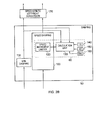
- control unit 30 receives the control signals from the joystick 32, and the control signals are passed to the demand scaling and gate shaping unit 40.
- This unit modifies the control signals in accordance with predetermined specifications, for example scaling a requested speed by a predetermined factor and limiting the spin which may be requested in combination with a given speed (gate shaping).
- the modified control signals from the demand scaling and gate shaping unit 40 are passed to damping unit 50 which damps the signals such that a smoother response of the electric wheelchair to changes in control signals from the user results.
- Damping unit 50 also comprises acceleration control unit 60 which will be described in more detail with reference to the following figures.
- the damped control signals are then converted into individual motor control signals which are passed to motor control units 70 and 80 which control motors 20 and 22 respectively.
- the speed control of motors 20 and 22 is performed in accordance with the known IR compensation technique using feedback signals received from each motor.
- TurnRadius L_axle 2 ⁇ Speed Spin
- centripetal acceleration Speed 2 TurnRadius
- centripetal acceleration is proportional to the product of speed and spin:
- This centripetal acceleration can then be considered in terms of the lifting force acting on the inside wheel of the wheelchair as it turns a corner (with a given TurnRadius) whereby the lifting force is proportional to the centripetal acceleration, which (from Equation 4) gives the relationship between the lifting force and the speed and spin of the wheelchair:
- F Lift ⁇ CentripetalAccel ⁇ F Lift K 1 ⁇ Speed ⁇ Spin
- K 1 is a proportionality constant which encompasses factors such as the mass of the wheelchair, the height of the centre of mass, the geometry of the wheelchair and the centripetal acceleration constant.
- the normal force F N is composed of the weight of the wheelchair acting on that wheel, less the lifting force due to the centripetal acceleration:
- F N WheelWeight - F Lift
- the traction limit can then be expressed as an acceleration limit, since the traction force is proportional to the acceleration, introducing a factor K 2 to quantify that proportionality:
- a Limit K 2 ⁇ ⁇ S ⁇ WheelWeight - K 2 ⁇ ⁇ S K 1 ⁇ Speed ⁇ Spin
- Damping unit 50 receives control signals from demand scaling and gate shaping unit 40 in terms of a requested speed and a requested spin.
- Speed damping unit 100 and spin damping unit 110 act on these values to produce damped versions which smooth out high frequency variations such that a smoother response of the electric wheelchair to varying control signals generated by joystick 32 results.
- the damped spin control signal is then passed on to be converted by conversion unit 170 into left and right motor control signals (as is discussed below).
- the damped speed control signal is passed to speed increment limiter 120 within acceleration control unit 60, which is configured to limit the rate of change of speed in dependence on a signal received from calculation unit 130 which also forms part of the acceleration control unit.
- the acceleration control unit 60 receives both the damped spin value and the output of speed increment limiter 120. In other words, calculation unit 130 receives the values which are passed by damping unit 50 to the conversion unit 170.
- the calculation unit 130 is configured to calculate an acceleration limit in accordance with equation 10 and on that basis to indicate a speed increment limit (i.e. an acceleration limit) to speed increment limiter 120.
- Calculation unit 130 has three further inputs which are discussed below with reference to Figure 3 .
- conversion unit 170 is configured to take speed and spin values and convert these into left and right motor control signals which are passed to motor controls 70 and 80 for driving the left and right motors 20, 22 respectively (i.e. inverting the relationships given in Equation 1 to calculate VL and VR for given values of speed and spin).
- Figure 2B illustrates a minor variation on the arrangement shown in Figure 2A , in which the speed imcrement limiter 120 forms part of the speed damping unit 100.
- Figure 3 schematically illustrates in more detail the inputs to the calculation unit 130.
- the calculation unit 130 receives predetermined values which form part of the configuration of the control unit 30, these being represented by turn traction limit 140, acceleration rate 150 and minimum acceleration increment 160. These values are explained in more detail below.
- the acceleration limit can be expressed in terms of a scaled maximum acceleration which has been predetermined for the wheelchair:
- the maximum programmed forward acceleration (A Max ) is stored as a preprogrammed value (item 150 in Figure 3 ) in the control unit.
- the factor K 3 is implemented as a programmable value called the Turn Traction Limit (TTL), which is also stored (item 140 in Figure 3 ) in the control unit.
- TTL may be implemented as a percentage value between 0 and 100.
- Equation 11 the assumption is made that A Max is the acceleration value at which the wheelchair loses traction for straight-line acceleration (i.e. no centripetal effect).
- the acceleration control unit 60 is configured to limit the increments by which the speed may be adjusted. These adjustments are typically applied at 10ms intervals, such that applying a limit to the size of the increments puts a limit on the acceleration of the wheelchair.
- the calculation unit 130 maintains a lower limit (A 0% ) on the acceleration limit it imposes, since allowing the acceleration increment to fall to zero results in a poor driveability feel for the wheelchair. Hence, the calculation unit 130 also makes reference to a minimum acceleration increment (item 160 in Figure 3 ).
- the operation of the acceleration control unit 60 schematically represented in Figures 1-3 is now described in terms of a series of steps as schematically set out in Figure 4 .
- the flow can be considered to begin at step 200 where the acceleration control unit 60 receives values from the previous iteration of damped speed and damped spin.
- the calculation unit 130 of the acceleration control unit 60 calculates the centripetal force factor, namely the product of the speed and the spin.
- This is then converted at step 220 into an acceleration limit for the wheelchair (see equation 9 above) and at step 230 a speed increment limit for the wheelchair is determined. This is applied at step 240 to the new damped speed and the flow returns to step 200.
- Figure 5 illustrates a simulation of a first example wheelchair wherein the acceleration increment limit imposed by the acceleration control unit is plotted against the joystick angle. Note that the units of the graph correspond to values used within a fixed point implementation of the acceleration control unit - corresponding percentages are added for ease of reference.
- the acceleration increment limit is plotted for three different standard speed settings of the wheelchair, namely five bar speed, three bar speed and one bar speed. In this example simulation, the wheelchair has been configured with the following settings: Forward Speed Max 90% Forward Speed Min 20% Turn Speed Max 19% Turn Speed Min 10% Forward Acceleration Max 40% Forward Acceleration Min 15% Turn Traction Limit 20%
- Figure 6 illustrates a simulation of a second example wheelchair wherein the acceleration increment limit imposed by the acceleration control unit is plotted against the joystick angle.
- the wheelchair was configured with the following settings: Forward Speed Max 95% Forward Speed Min 30% Turn Speed Max 25% Turn Speed Min 20% Forward Acceleration Max 50% Forward Acceleration Min 25% Turn Traction Limit 70%
- This second example wheelchair is somewhat heavier than that used for the simulation shown in Figure 5 , and has a relatively high centre of mass.
- the programmed acceleration rates and turn speeds are slightly higher than typical programmed values. It was nevertheless found to be possible to stop this wheelchair from losing traction, but a higher turn traction limit of 70% was required to prevent slippage.
- FIG. 7 schematically illustrates a general purpose computing device 300 of the type that may be used to implement the above described techniques.
- the general purpose computing device 300 includes a central processing unit 302, a random access memory 304 and a read only memory 306, connected together via bus 322.
- the general purpose computing device may be extended to further comprise a network interface card 308, a hard disk drive 310, a display driver 312 and monitor 314 and a user input/output circuit 316 with a keyboard 318 and mouse 320 all connected via the common bus 322.
- the central processing unit 302 will execute computer program instructions that may for example be stored in the random access memory 304 and/or the read only memory 306.
- These core components of the general purpose computing device are labelled 330 in Figure 7 .
- the additional components outside the dashed box 330 may additionally be connected, for example when the control system is connected to a diagnostic set-up for pre-programming or for troubleshooting.
- program instructions could be additionally retrieved from the hard disk drive 310 or dynamically downloaded via the network interface card 308.
- the results of the processing performed may be displayed to a user or an engineer via a connected display driver 312 and monitor 314.
- User inputs for controlling the operation of the general purpose computing device 300 may be received via a connected user input output circuit 316 from the keyboard 318 or the mouse 320.
- the computer program could be written in a variety of different computer languages.
- the computer program may be stored locally on a recording medium or dynamically downloaded to the general purpose computing device 300.
- the general purpose computing device 300 can perform the above described techniques and can be considered to form an apparatus for performing the above described technique.
- the architecture of the general purpose computing device 300 could vary considerably and Figure 7 is only one example.
Landscapes
- Engineering & Computer Science (AREA)
- Power Engineering (AREA)
- Transportation (AREA)
- Mechanical Engineering (AREA)
- Chemical & Material Sciences (AREA)
- Organic Chemistry (AREA)
- Life Sciences & Earth Sciences (AREA)
- Animal Behavior & Ethology (AREA)
- Public Health (AREA)
- Veterinary Medicine (AREA)
- General Health & Medical Sciences (AREA)
- Health & Medical Sciences (AREA)
- Sustainable Development (AREA)
- Sustainable Energy (AREA)
- Electric Propulsion And Braking For Vehicles (AREA)
Applications Claiming Priority (1)
| Application Number | Priority Date | Filing Date | Title |
|---|---|---|---|
| GB1017066.0A GB2484467B (en) | 2010-10-11 | 2010-10-11 | A controller and control method for a motorised vehicle |
Publications (2)
| Publication Number | Publication Date |
|---|---|
| EP2497680A2 true EP2497680A2 (de) | 2012-09-12 |
| EP2497680A3 EP2497680A3 (de) | 2017-08-16 |
Family
ID=43304335
Family Applications (1)
| Application Number | Title | Priority Date | Filing Date |
|---|---|---|---|
| EP11180519.8A Withdrawn EP2497680A3 (de) | 2010-10-11 | 2011-09-08 | Steuerung und Steuerungsverfahren für motorisiertes Fahrzeug |
Country Status (3)
| Country | Link |
|---|---|
| US (1) | US8731754B2 (de) |
| EP (1) | EP2497680A3 (de) |
| GB (1) | GB2484467B (de) |
Cited By (2)
| Publication number | Priority date | Publication date | Assignee | Title |
|---|---|---|---|---|
| WO2015038007A1 (en) * | 2013-09-13 | 2015-03-19 | Dynamic Controls | Method for producing a control profile to operate a mobility device |
| CN104787184A (zh) * | 2015-03-30 | 2015-07-22 | 雅迪科技集团有限公司 | 一种电动车倒车推车控制系统及其控制方法 |
Families Citing this family (3)
| Publication number | Priority date | Publication date | Assignee | Title |
|---|---|---|---|---|
| US7931101B2 (en) * | 2006-10-13 | 2011-04-26 | Invacare Corporation | Proportional joystick with integral switch |
| JP5470504B2 (ja) * | 2011-12-01 | 2014-04-16 | パナソニック株式会社 | 電動車両、および、電動車両の制御方法 |
| JPWO2013190821A1 (ja) * | 2012-06-19 | 2016-02-08 | 住友重機械工業株式会社 | フォークリフト用のモータ駆動装置およびそれを用いたフォークリフト |
Citations (3)
| Publication number | Priority date | Publication date | Assignee | Title |
|---|---|---|---|---|
| US5033000A (en) | 1988-06-09 | 1991-07-16 | Natco Corporation | Variable keyed power distribution and control system for motorized wheelchair |
| US5307888A (en) | 1991-09-12 | 1994-05-03 | Giat Industries | Method and apparatus for controlling the steering of a vehicle that is tracked or that has non-steerable wheels |
| US20100007299A1 (en) | 2008-07-11 | 2010-01-14 | Curtis Instruments, Inc. | Systems and methods for dynamically compensating motor resistance in electric motors |
Family Cites Families (12)
| Publication number | Priority date | Publication date | Assignee | Title |
|---|---|---|---|---|
| JP2660992B2 (ja) * | 1987-02-06 | 1997-10-08 | アイシン・エィ・ダブリュ株式会社 | 電動機付車両の駆動力制御装置 |
| JP3320961B2 (ja) * | 1995-10-31 | 2002-09-03 | ヤマハ発動機株式会社 | 車両速度制御装置 |
| US6615937B2 (en) * | 1999-07-30 | 2003-09-09 | Invacare Corporation | Motorized wheelchairs |
| JP2001104396A (ja) * | 1999-10-06 | 2001-04-17 | Matsushita Electric Ind Co Ltd | 電動車椅子 |
| US7958237B2 (en) * | 2001-01-23 | 2011-06-07 | Pearl Software, Inc. | Method for managing computer network access |
| JP2004229716A (ja) * | 2003-01-28 | 2004-08-19 | Kayaba Ind Co Ltd | 電動車椅子 |
| US7865275B2 (en) * | 2003-10-10 | 2011-01-04 | Dynamic Controls Limited | Method and apparatus for controlling an electric vehicle function |
| US20050087375A1 (en) * | 2003-10-24 | 2005-04-28 | Angus Steele | Active stability wheel chair based on positive angle sensors |
| JP2006109547A (ja) * | 2004-09-30 | 2006-04-20 | Sanyo Electric Co Ltd | 電動車及び電動車駆動用制御プログラム |
| EP1972486A1 (de) * | 2007-03-19 | 2008-09-24 | Invacare International Sàrl | Motorisierter Rollstuhl |
| GB2469654B (en) * | 2009-04-21 | 2013-10-09 | Penny & Giles Controls Ltd | A controller and control method for a motorised vehicle |
| GB2478956B (en) * | 2010-03-24 | 2015-04-22 | Penny & Giles Controls Ltd | A controller and control method for a motorised vehicle |
-
2010
- 2010-10-11 GB GB1017066.0A patent/GB2484467B/en not_active Expired - Fee Related
-
2011
- 2011-09-08 EP EP11180519.8A patent/EP2497680A3/de not_active Withdrawn
- 2011-10-05 US US13/253,733 patent/US8731754B2/en not_active Expired - Fee Related
Patent Citations (3)
| Publication number | Priority date | Publication date | Assignee | Title |
|---|---|---|---|---|
| US5033000A (en) | 1988-06-09 | 1991-07-16 | Natco Corporation | Variable keyed power distribution and control system for motorized wheelchair |
| US5307888A (en) | 1991-09-12 | 1994-05-03 | Giat Industries | Method and apparatus for controlling the steering of a vehicle that is tracked or that has non-steerable wheels |
| US20100007299A1 (en) | 2008-07-11 | 2010-01-14 | Curtis Instruments, Inc. | Systems and methods for dynamically compensating motor resistance in electric motors |
Cited By (3)
| Publication number | Priority date | Publication date | Assignee | Title |
|---|---|---|---|---|
| WO2015038007A1 (en) * | 2013-09-13 | 2015-03-19 | Dynamic Controls | Method for producing a control profile to operate a mobility device |
| US9904449B2 (en) | 2013-09-13 | 2018-02-27 | Dynamic Controls | Method for producing a control profile to operate a mobility device |
| CN104787184A (zh) * | 2015-03-30 | 2015-07-22 | 雅迪科技集团有限公司 | 一种电动车倒车推车控制系统及其控制方法 |
Also Published As
| Publication number | Publication date |
|---|---|
| GB2484467A (en) | 2012-04-18 |
| US8731754B2 (en) | 2014-05-20 |
| GB2484467B (en) | 2015-07-22 |
| GB201017066D0 (en) | 2010-11-24 |
| US20120265384A1 (en) | 2012-10-18 |
| EP2497680A3 (de) | 2017-08-16 |
Similar Documents
| Publication | Publication Date | Title |
|---|---|---|
| EP3632774B1 (de) | Steuergerät für lenksystem und verfahren zur steuerung des lenksystems | |
| US9016410B2 (en) | Controller and control method for a motorised vehicle | |
| JP5126357B2 (ja) | 車両の操舵装置 | |
| US9266435B2 (en) | Controller and control method for a motorised vehicle | |
| US8234044B2 (en) | Steering control system for vehicle | |
| US20150088380A1 (en) | Active torque steer compensation during negative powertrain torque for hybrid and electric vehicles | |
| EP2497680A2 (de) | Steuerung und Steuerungsverfahren für motorisiertes Fahrzeug | |
| CN108778904A (zh) | 电动助力转向装置 | |
| US9132854B2 (en) | Fault tolerant apparatus and method for an independent controlled steering in a four wheel drive system | |
| KR20030030833A (ko) | 전동파워 스티어링 제어장치 | |
| EP0842841B1 (de) | Steuerung für eine elektrische Servolenkung | |
| US10864127B1 (en) | System and method for correcting steering of a vehicle | |
| JP5863344B2 (ja) | 規範応答演算装置およびそれを用いた車両用操舵装置 | |
| JP2010163109A (ja) | 電動パワーステアリング制御装置 | |
| US12351039B2 (en) | Method for controlling a motion of a vehicle, data processing apparatus, computer program, computer-readable storage medium, and vehicle propulsion system | |
| US9738313B2 (en) | Motor-assisted joint system for articulated bus | |
| CN112449624B (zh) | 操舵控制装置以及操舵控制方法 | |
| JP2670626B2 (ja) | 車両の姿勢制御装置 | |
| JP4556665B2 (ja) | 車両用操舵制御装置 | |
| US11897559B2 (en) | Steering control device and power steering device | |
| JP4432601B2 (ja) | ステアリング装置 | |
| US20230034838A1 (en) | Vehicle steering device | |
| JP2000302054A (ja) | 車両の操舵角制御装置 | |
| JP2011051412A (ja) | 操舵制御装置 |
Legal Events
| Date | Code | Title | Description |
|---|---|---|---|
| PUAI | Public reference made under article 153(3) epc to a published international application that has entered the european phase |
Free format text: ORIGINAL CODE: 0009012 |
|
| AK | Designated contracting states |
Kind code of ref document: A2 Designated state(s): AL AT BE BG CH CY CZ DE DK EE ES FI FR GB GR HR HU IE IS IT LI LT LU LV MC MK MT NL NO PL PT RO RS SE SI SK SM TR |
|
| AX | Request for extension of the european patent |
Extension state: BA ME |
|
| RAP1 | Party data changed (applicant data changed or rights of an application transferred) |
Owner name: PENNY & GILES CONTROLS LIMITED |
|
| 17P | Request for examination filed |
Effective date: 20130115 |
|
| PUAL | Search report despatched |
Free format text: ORIGINAL CODE: 0009013 |
|
| AK | Designated contracting states |
Kind code of ref document: A3 Designated state(s): AL AT BE BG CH CY CZ DE DK EE ES FI FR GB GR HR HU IE IS IT LI LT LU LV MC MK MT NL NO PL PT RO RS SE SI SK SM TR |
|
| AX | Request for extension of the european patent |
Extension state: BA ME |
|
| RIC1 | Information provided on ipc code assigned before grant |
Ipc: B60W 30/18 20120101ALI20170713BHEP Ipc: C07C 273/16 20060101ALI20170713BHEP Ipc: A61G 5/04 20130101ALI20170713BHEP Ipc: B60L 3/10 20060101ALI20170713BHEP Ipc: B60L 15/20 20060101AFI20170713BHEP |
|
| STAA | Information on the status of an ep patent application or granted ep patent |
Free format text: STATUS: EXAMINATION IS IN PROGRESS |
|
| 17Q | First examination report despatched |
Effective date: 20180808 |
|
| STAA | Information on the status of an ep patent application or granted ep patent |
Free format text: STATUS: THE APPLICATION IS DEEMED TO BE WITHDRAWN |
|
| 18D | Application deemed to be withdrawn |
Effective date: 20190629 |