EP2495963A2 - Videoanzeigevorrichtung und Videoverarbeitungsverfahren - Google Patents
Videoanzeigevorrichtung und Videoverarbeitungsverfahren Download PDFInfo
- Publication number
- EP2495963A2 EP2495963A2 EP11195985A EP11195985A EP2495963A2 EP 2495963 A2 EP2495963 A2 EP 2495963A2 EP 11195985 A EP11195985 A EP 11195985A EP 11195985 A EP11195985 A EP 11195985A EP 2495963 A2 EP2495963 A2 EP 2495963A2
- Authority
- EP
- European Patent Office
- Prior art keywords
- video signal
- format
- video
- resolution
- processing
- Prior art date
- Legal status (The legal status is an assumption and is not a legal conclusion. Google has not performed a legal analysis and makes no representation as to the accuracy of the status listed.)
- Withdrawn
Links
Images


Classifications
-
- H—ELECTRICITY
- H04—ELECTRIC COMMUNICATION TECHNIQUE
- H04N—PICTORIAL COMMUNICATION, e.g. TELEVISION
- H04N9/00—Details of colour television systems
- H04N9/64—Circuits for processing colour signals
- H04N9/642—Multi-standard receivers
-
- H—ELECTRICITY
- H04—ELECTRIC COMMUNICATION TECHNIQUE
- H04N—PICTORIAL COMMUNICATION, e.g. TELEVISION
- H04N21/00—Selective content distribution, e.g. interactive television or video on demand [VOD]
- H04N21/40—Client devices specifically adapted for the reception of or interaction with content, e.g. set-top-box [STB]; Operations thereof
- H04N21/43—Processing of content or additional data, e.g. demultiplexing additional data from a digital video stream; Elementary client operations, e.g. monitoring of home network or synchronising decoder's clock; Client middleware
- H04N21/44—Processing of video elementary streams, e.g. splicing a video clip retrieved from local storage with an incoming video stream, rendering scenes according to MPEG-4 scene graphs
- H04N21/4402—Processing of video elementary streams, e.g. splicing a video clip retrieved from local storage with an incoming video stream, rendering scenes according to MPEG-4 scene graphs involving reformatting operations of video signals for household redistribution, storage or real-time display
- H04N21/440263—Processing of video elementary streams, e.g. splicing a video clip retrieved from local storage with an incoming video stream, rendering scenes according to MPEG-4 scene graphs involving reformatting operations of video signals for household redistribution, storage or real-time display by altering the spatial resolution, e.g. for displaying on a connected PDA
-
- H—ELECTRICITY
- H04—ELECTRIC COMMUNICATION TECHNIQUE
- H04N—PICTORIAL COMMUNICATION, e.g. TELEVISION
- H04N21/00—Selective content distribution, e.g. interactive television or video on demand [VOD]
- H04N21/40—Client devices specifically adapted for the reception of or interaction with content, e.g. set-top-box [STB]; Operations thereof
- H04N21/43—Processing of content or additional data, e.g. demultiplexing additional data from a digital video stream; Elementary client operations, e.g. monitoring of home network or synchronising decoder's clock; Client middleware
- H04N21/44—Processing of video elementary streams, e.g. splicing a video clip retrieved from local storage with an incoming video stream, rendering scenes according to MPEG-4 scene graphs
- H04N21/4408—Processing of video elementary streams, e.g. splicing a video clip retrieved from local storage with an incoming video stream, rendering scenes according to MPEG-4 scene graphs involving video stream encryption, e.g. re-encrypting a decrypted video stream for redistribution in a home network
Definitions
- Embodiments described herein relate generally to a video display apparatus and a video processing method for processing a video signal.
- TV receivers which allow the user to enjoy a game by connecting a game machine to them are now in common use.
- the user connects a game machine to an external input terminal of a TV receiver and causes the game machine to operate, whereby video and audio generated by the game machine are output from the display and the speakers of the TV receiver. That is, the user can enjoy a game using a large screen by using a TV receiver as an external output device of a game machine.
- TV receivers are compatible with various kinds of input video.
- such TV receivers have D terminals (DI-D5 terminals), a component terminal, an S terminal, an RCA terminal, a composite video signal terminal, an HDMI (high-definition multimedia interface) terminal, etc. and receive input video through those terminals.
- D terminals DI-D5 terminals
- component terminal an S terminal
- RCA terminal an RCA terminal
- composite video signal terminal an HDMI (high-definition multimedia interface) terminal, etc.
- HDMI high-definition multimedia interface
- Recent TV receivers may be provided with techniques capable of improving the image quality of input video by various kinds of super-resolution processing.
- TV receivers having a reconstruction-based super-resolution processing function can realize video having a higher resolution than original video.
- TV receivers which have a self-congruence-type super-resolution processing function capable of increasing resolutions in oblique directions and a color super-resolution processing function are developed.
- one embodiment provides a video display apparatus, including: a converter configured to perform a format conversion in which a video signal having a first format is converted into a video signal having another format, the another format having the number of color sampling points smaller than that of the first format; a video processor configured to perform a video processing in which a video signal is processed to be output toward a display module, the video processor including a first super-resolution processor configured to perform at least one of self-congruence-type super-resolution processing and color super-resolution processing on the video signal having the another format; and a controller configured: to judge whether an input video signal has the first format or not; to subject the input video signal to the video processing by the video processor while avoiding the converter, if judged that the input video signal does not have the first format; and to subject the input video signal to the format conversion by the converter, and then, to subject the converted input video signal to the video processing by the video processor, if judged that the input video signal has the first format.
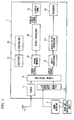
- Fig. 1 illustrates a system configuration of a TV receiver 1 (video display apparatus) according to the embodiment of the invention.
- the TV receiver I is equipped with a tuner 11, an external input terminal unit 12, a pre-stage module 13, a frame memory 14, a video processor 30, a selector 21, a controller 20, an audio processor 16, and an audio delay processor 17.
- the frame memory 14 and the video processor 30 are separated from each other for convenience of description, the frame memory 14 may be regarded as part of the video processor 30 and the frame memory 14, the video processor 30, etc. may be implemented as a single system LSI.
- An antenna 2 is connected to the tuner 11.
- a game machine 3 having a game manipulation unit 4 is connected to the external input terminal unit 12, and a video signal and an audio signal are output to a display panel 15 (display module) and speakers 18 (audio output modules), respectively.
- the tuner 11 tunes in to and processes a broadcast signal or the like of a satellite broadcast such as a BS broadcast or a CS broadcast, a ground-wave broadcast, or the like and outputs a video signal and an audio signal.
- the tuner 11 can also receive a signal that is transmitted by a communication line such as a cable TV line.
- the external input terminal unit 12 has a D terminal (D1-D5 terminals), a component terminal, an S terminal, an RCA terminal, a composite video signal terminal, an HDMI (high-definition multimedia interface) terminal, etc.
- the external input terminal unit 12 receives a video signal and an audio signal as external input signals from an external apparatus such as the game machine 3 or a hard disk recorder in the form of a composite signal, an S terminal signal, color difference signals, a D-sub signal, or the like.
- the TV receiver 1 accommodates various video formats such as 480i, 480p, 720p, 1,080i, and 1,080p. Furthermore, the TV receiver 1 accommodates various chroma formats for narrowing the bandwidth of color signals and can process video signals of the 4:4:4 format (no decimation), the 4:2:2 format (the sampling points of color difference signals are decimated to 1/2 of those of a luminance signal), the 4:2:0 format and the 4:1:1 format (the sampling points of color difference signals are decimated to 1/4 of those of a luminance signal), etc.
- the pre-stage module 13 receives plural sets of a video signal and an audio signal from the tuner 11 and the external input terminal unit 12 and performs pre-sage processing on a selected video signal and audio signal. As described later, the pre-stage module 13 has an A/D converting function of converting an analog video signal into a digital video signal and a chroma format converting function. The pre-stage module 13 outputs a pre-stage-processed video signal and audio signal to the frame memory 14 and the audio processor 16, respectively.
- the video signal is supplied via the frame memory 14 to the video processor 30 (described later in detail), where it is subjected to signal processing.
- a resulting video display signal is output to the display panel 15.
- the audio signal is subjected to signal processing in the audio processor 16.
- a resulting signal is delayed by the audio delay processor 17 according to a delay time of the video signal, and output to the speakers 18.
- the controller 20 is a CPU which controls the entire TV receiver 1 according to, for example, the setting of the selector 21 which receives a user instruction.
- the controller 20 controls the pre-stage module 13 and the video processor 30 according to the format of an input video signal so that the video signal is subjected to video processing that is most suitable for its format If the pre-stage module 13 is to select, for example, a video signal of the 4:4:4 format that is output from the D terminal of the external input terminal unit 12, the controller 20 causes the pre-stage module 13 to convert the video signal of the 4:4:4 format into a video signal of the 4:2:2, for example, and output the latter.
- the controller 20 controls the video processor 30 so that the chroma-format-converted video signal is subjected to super-resolution processing of both of a 4:2:2 super-resolution module and a 4:4:4 super-resolution module.
- the selector 21 determines, according to a user manipulation, which of a video signal supplied from the tuner 11 and a video signal supplied from the external input terminal unit 12 should be selected, and gives the controller 20 an instruction to that effect.
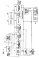
- Fig. 2 is a block diagram showing a specific configuration corresponding to Fig. 1 , in particular, specific configurations of the pre-stage module 13 and the video processor 30.
- the pre-stage module 13 of the TV receiver 1 is composed of an A/D converter 27, selectors 28, and a chroma format converter 29.
- the A/D converter 27 converts an input video signal into a digital signal and outputs the latter.
- the A/D converter 27 can convert an input video signal into a digital signal through oversampling.
- the selectors 28, which are controlled by the controller 20, are configured so as to supplies the output signal of the A/D converter 27 to the chroma format converter 29 if it is a video signal of the 4:4:4 format and has a relatively low resolution (480i, 480p, 720p, or the like) and directly to the frame memory 14 if it is a video signal of any of the other formats.
- the selectors 28 may be configured so that only a video signal of the 4:4:4 format that is supplied via the D terminal among various kinds of output signals of the A/D converter 27 is supplied to the chroma format converter 29.
- the chroma format converter 29 converts the received video signal of the 4:4:4 format into a video signal of a chroma format that is smaller in the number of color sampling points than the 4:4:4 format, such as the 4:2:2 format, the 4:2:0 format, or the 4:1:1 format, and outputs the latter to the frame memory 14.
- the chroma format converter 29 may be configured so as to convert a video signal of the 4:4:4 format that is supplied via the D terminal into a video signal of the 4:2:2 format.
- the pre-stage module 13 converts at least a video signal of the 4:4:4 format that is supplied via the D terminal into a video signal of the 4:2:2 format, and supplies the latter to the frame memory 14.
- the resolution of color signal components is lowered when a video signal of the 4:4:4 format is converted into a video signal of the 4:2:2 format.
- the A/D converter 27 performs A/D conversion through oversampling, image quality degradation due to resolution reduction caused by the chroma format conversion is slight.
- the TV receiver 1 is equipped with the frame memory 14, the video processor 30, a video analyzer 22, a sync signal generator 41, a clock unit 42, a sync correction module 43, and a display sync signal generator 44.
- the video processor 30 is composed of an IP conversion/NR module 31, a 4:2:2 super-resolution module 32, a 4:4:4 super-resolution module 33, a scaler 34, an image quality enhancer 35, and a frame-rate-doubling processor 36.
- the video analyzer 22 analyzes a video signal that is stored in the frame memory 14 and outputs frame information to be used by the controller 20 in controlling the video processor 30. For example, the video analyzer 22 acquires luminance histogram data of one frame by dividing a luminance level dynamic range into n parts and counting the numbers of pixels, corresponding to respective luminance levels 1-n, of a video signal of one frame. Furthermore, the video analyzer 22 detects, for example, a frequency distribution of a video signal.
- the sync signal generator 41 generates sync signals by separating them from an input video signal.
- the clock unit 42 generates a signal having a predetermined frequency
- the display sync signal generator 44 generates sync signals (display sync signals) for a display video signal to be displayed by the display panel 15 based on the signal generated by the clock unit 42.
- the sync correction module 43 synchronizes the input sync signals generated by the sync signal generator 41 and the display sync signals generated by the display sync signal generator 44 with each other.
- a flat panel display hereinafter referred to as FPD
- horizontal and vertical sync signals (hereinafter referred to as display sync signals) for display of the FPD are generated asynchronously with horizontal and vertical sync signals (hereinafter referred to as input sync signals) of an input video signal.
- the frequencies of the display sync signals of the FPD have allowable ranges, and the FPD can always perform display based on an input video signal as long as the frequencies of input sync signals are within the allowable ranges (corresponding periods will be hereinafter referred to as sync compensation periods).
- the sync correction module 43 synchronizes display sync signals with input sync signals.
- the sync correction module 43 generates display sync signals that are synchronized with input sync signals that are in predetermined sync compensation periods, and outputs the generated display sync signals to the display panel 15.
- the IP (interface/progressive) conversion/NR (noise reduction) module 31 of the video processor 30 performs IP conversion processing of converting an interlaced video signal into a progressive video signal and noise reduction processing of reducing roughness, a flicker, blocking noise, and mosquito noise of video. That is, the IP conversion/NR module 31 is composed of an IP conversion module and an NR module. No IP conversion processing is performed on a progressive input video signal. Noise reduction processing may be omitted an input video signal contains only little noise. That is, the IP conversion/NR module 31 performs at least one of IP conversion processing and noise reduction processing.
- the 4:2:2 super-resolution module 32 is equipped with a self-congruence-type super-resolution processor and a color super-resolution processor.
- the self-congruence-type super-resolution processor generates a signal between existing pixels using a signal that is located in the vicinity of an edge and is similar to it utilizing a property (self-congruence) that an image similar to a certain image exists in the frame. That is, the self-congruence-type super-resolution processor processes an edge portion such as a boundary between objects, a line, or the like, detects a portion that similar in a video signal to the edge portion from a peripheral portion of the edge portion, and generates a higher resolution image by superimposing resulting images on each other.
- the processing of the self-congruence-type super-resolution processor increases the resolution of an image and thereby increases the sharpness of video further.
- the color super-resolution processor performs such self-congruence-type super-resolution processing on color signals and thereby doubles the color resolution.
- the color super-resolution processor can thus increase the color sharpness and fineness of an image.
- a video signal of the 4:2:0 format may be used in which color sampling points are decimated to 1/2 points in each of the horizontal and vertical directions.
- Performing color super-resolution processing on such a video signal makes it possible to restore color information that was partially lost due to the compression to I12 of brightness information and to thereby reproduce highly colorful video. That is, the color super-resolution processor can increase the color information amount to fine details, thereby suppress blurring in edge portions and increase sharpness, and consequently increase the fineness of the entire image.
- the color super-resolution processor performs congruent points search processing and phase focusing processing.
- the color super-resolution processor detects a pixel that is self-congruent with an input pixel by congruent points search processing and uses it as a new sampling point.
- a phase offset occurs that the pixel positions of color different signals are shifted in the vertical direction from those of a luminance signal.
- the color super-resolution processor performs phase focusing processing to correct the phase of color signals according to that of a luminance signal.
- the 4:2:2 super-resolution module 32 cannot perform signal processing on a video signal of the 4:4:4 format. However, as for a video signal of the 4:4:4 format, a sufficiently high resolution can be obtained without color super resolution processing because color signals were not subjected to decimation processing.
- Processing that is performed by the 4:2:2 super-resolution module 32 is associated with vertical pixel interpolation, and basically the 4:2:2 super-resolution module 32 cannot process a video signal whose number of pixels is larger than 1/2 of the number of pixels in the vertical direction of the display panel 15.
- the 4:2:2 super-resolution module 32 may be configured so as to perform self-congruence-type super-resolution processing and color super-resolution processing on a video signal whose number of pixels is larger than 1/2 of the number of pixels in the vertical direction of the display panel 15 with an assumption that pixel compression processing or decimation processing is performer.
- the 4:2:2 super-resolution module 32 may be configured so as to perform super-resolution processing on not only 480i and 480p video signals but also a 720p video signal of the 4:2:2 format.
- the 4:2:2 super-resolution module 32 cannot perform super-resolution processing on all kinds of video signals because of limitations relating to the number of pixels in the vertical direction and the chroma format. For example, where a 480p video signal that is input to the D terminal has the 4:4:4 format, the 4:2:2 super-resolution module 32 cannot perform super-resolution processing on this video signal. However, even a 480p video signal of the 4:4:4 format which is input to the D terminal is not sufficiently high in resolution and it is desired that such a video signal be increased in resolution by super-resolution processing.
- a 480p video signal of the 4:4:4 format which is input to the D terminal is converted into a video signal of the 4:2:2 format, which is supplied to the 4:2:2 super-resolution module 32.
- This video signal is increased in resolution by self-congruence-type super-resolution processing and color super-resolution processing.
- selectors 37 supply this video signal to the 4:4:4 super-resolution module 33 via the 4:2:2 super-resolution module 32.
- the selectors 37 supply any of the other kinds of video signals directly to the 4:4:4 super-resolution module 33, that is, without causing them to be processed by the 4:2:2 super-resolution module 32.
- the selectors 37 supply it to the 4:2:2 super-resolution module 32.
- a video signal of the 4:4:4 format which is input via the D terminal is converted into a video signal of the 4:2:2 format, which is supplied to the 4:2:2 super-resolution module 32 and subjected to self-congruence-type super-resolution processing and color super-resolution processing there.
- the 4:2:2 super-resolution module 32 may have a plural frames super-resolution processor which performs super-resolution processing for each set of frames.
- the 4:4:4 super-resolution module 33 which is to perform reconstruction-based super-resolution processing, generates video having a higher resolution than original video by creating high frequency components and sharpening the video by generating new pixel data between pixels. That is, the 4:4:4 super-resolution module 33 restores a video signal having a high resolution (second resolution) by increasing pixels by estimating intrinsic pixel values from a video signal having a low resolution (first resolution).
- intrinsic pixel values means, for example, values of pixels of a video signal that would be obtained when a subject that was shot to obtain a video signal having a low resolution (first resolution) is shot with a camera having a high resolution (second resolution).
- the term "to increase pixels through estimation” means estimating intrinsic pixel values by detecting a feature of a subject image and using a high-correlation image in the same or another frame, and employing them as pixel values of new pixels (correlation between images is utilized).
- the 4:4:4 super-resolution module 33 uses a known technique such as a technique of restoring video having high frequency components whose frequencies are higher than a Nyquist frequency that is determined by a sampling frequency of input video.
- the scaler 34 performs scaling processing of adjusting the specifications of a video signal to those of the display panel 15 when the former are currently different from the latter. For example, when the aspect ratio of an input video signal is 4:3 and that of the display panel IS is 16:9, the scaler 34 converts the input video signal into a display video signal having an aspect ratio 16:9.
- the image quality enhancer 35 performs image quality enhancement processing such as color correction (gamma correction, white balance adjustment, brightness adjustment, and contrast adjustment), sharpness adjustment, edge enhancement, and response speed raising.
- image quality enhancement processing such as color correction (gamma correction, white balance adjustment, brightness adjustment, and contrast adjustment), sharpness adjustment, edge enhancement, and response speed raising.
- the frame-rate-doubling processor 36 performs doubling processing of doubling the frame rate (50 Hz to 100 Hz, 60 Hz to 120 Hz) and thereby reducing the degree of afterimage.
- the frame-rate-doubling processing may be either of a method in which an interpolation frame to be inserted between two consecutive frames is generated by motion compensation prediction or a simple double repeat method in which the same image is simply displayed two times.
- a video signal inducted in the antenna 2 is selected by the tuner 11 through tuning and supplied to the pre-stage module 13.
- a video signal supplied from the game machine 3 is supplied to the pre-stage module 13 via the external input terminal unit 12.
- a high-resolution video signal e.g., 1,080p video signal of the 4:4:4 format
- the input video signal is an analog signal
- the A/D converter 27 of the pre-stage module 13 converts it into a digital signal.
- the controller 20 detects that the video format of the selected video signal is the 4:4:4 format and is high in resolution (S3: yes) and supplies it to the frame memory 14 and stores it therein by controlling the selectors 28 of the pre-stage module 13.
- the video processor 30 reads the video signal from the frame memory 14 and processes it in its individual modules.
- the controller 20 supplies an output signal of the IP conversion/NR module 31 to the 4:4:4 super-resolution module 33 by controlling the selectors 37.
- the video signal that has been read from the frame memory 14 is subjected to NR processing in the IP conversion/NR module 31 and then subjected to reconstruction-based super-resolution processing (step S7) and thereby increased in resolution.
- An output video signal of the 4:4:4 super-resolution module 33 is subjected to respective pieces of processing in the scaler 34, the image quality enhancer 35, and the frame-rate doubler 36, and a resulting display video signal is supplied to the display panel 15.
- the A/D converter 27 of the pre-stage module 13 converts a 480p analog video signal which is input via the D terminal into a digital signal.
- the controller 20 detects that the video format of the selected video signal is the 4:4:4 format is relatively low in resolution (S3: no; S4: yes), the process moves to step S5. More specifically, the controller 20 supplies the video signal to the chroma format converter 29 by controlling the selectors 28 of the pre-stage module 13.
- the chroma format converter 29 converts the video format of the received video signal to, for example, the 4:2:2 format by decreasing the number of sampling points of the color signals.
- a chroma-format-converted video signal is supplied to the frame memory 14 and stored therein.
- the video processor 30 reads the video signal from the frame memory 14 and processes it in its individual modules.
- the controller 20 supplies an output signal of the IP conversion/NR module 31 to the 4:2:2 super-resolution module 32 by controlling the selectors 37.
- the video signal is subjected to subjected to self-congruence-type super-resolution processing and color super-resolution processing and thereby increased in resolution (step S6), whereby the luminance signal and the color signals are increased in resolution in oblique directions.
- step S6 the video signal having the relatively low resolution which has been input via the D terminal is increased in resolution.
- An output video signal of the 4:2:2 super-resolution module 32 is supplied to the 4:4:4 super-resolution module 33 and subjected to reconstruction-based super-resolution processing there (step S7).
- An output video signal of the 4:4:4 super-resolution module 33 is subjected to respective pieces of processing in the scaler 34, the image quality enhancer 35, and the frame-rate doubler 36, and a resulting display video signal is supplied to the display panel 15.
- a video signal of the 4:4:4 format having a relatively low resolution is converted into a video signal of the 4:2:2 format, which is subjected to super-resolution processing etc.
- the number of color sampling points is decreased by the conversion into the 4:2:2 format, image quality degradation due to the decrease in the number of sampling points is slight because of oversampling of A/D conversion.
- the video signal is subjected to self-congruence-type super-resolution processing and color super-resolution processing by virtue of the conversion into the 4:2:2 format, the resolution can be increased sufficiently and the image quality can be increased greatly.
- a video signal of the 4:4:4 format that is input from the game machine 3 or the like via the D terminal can be increased or enhanced sufficiently in resolution and image quality.
- Fig. 4 illustrates a functional configuration of a TV receiver 1' according to a modification of the embodiment. Modules, sections, etc. in Fig. 4 having the same ones in Fig. 2 will be given the same reference numerals and will not be described in detail.
- This modification is different from the embodiment in that a chroma format converter 29' is provided in place of the chroma format converter 29.
- the chroma format converter 29' perform chroma format conversion according to conversion parameters which are supplied from the controller 20. If an input video signal is of the 4:4:4 format and has a relatively low resolution (e.g., 480i, 480p, or 720p), the controller 20 gives the chroma format converter 29' conversion parameters for converting the input video signal into a video signal of a chroma format (e.g., 4,2:2, 4:2:0, or 4:1:1) in which the number of color sampling points is smaller than in the 4:4:4 format.
- a chroma format e.g., 4,2:2, 4:2:0, or 4:1:1
- the controller 20 gives the chroma format converter 29' conversion parameters for causing the chroma format converter 29' to output the received video signal as it is, that is, without performing any chroma format conversion on it.
- the chroma format converter 29' converts a video signal of the 4:4:4 format having a relatively low resolution into a video signal of a chroma format (e.g., 4:2:2, 4:2:0, or 4:1:1) that has a smaller number of color sampling points than the 4:4:4 format and outputs the latter to the frame memory 14.
- a chroma format e.g., 4:2:2, 4:2:0, or 4:1:1
Applications Claiming Priority (1)
| Application Number | Priority Date | Filing Date | Title |
|---|---|---|---|
| JP2011044373A JP5112528B2 (ja) | 2011-03-01 | 2011-03-01 | 映像表示装置及び映像処理方法 |
Publications (1)
| Publication Number | Publication Date |
|---|---|
| EP2495963A2 true EP2495963A2 (de) | 2012-09-05 |
Family
ID=45476355
Family Applications (1)
| Application Number | Title | Priority Date | Filing Date |
|---|---|---|---|
| EP11195985A Withdrawn EP2495963A2 (de) | 2011-03-01 | 2011-12-29 | Videoanzeigevorrichtung und Videoverarbeitungsverfahren |
Country Status (2)
| Country | Link |
|---|---|
| EP (1) | EP2495963A2 (de) |
| JP (1) | JP5112528B2 (de) |
Cited By (3)
| Publication number | Priority date | Publication date | Assignee | Title |
|---|---|---|---|---|
| CN103152540A (zh) * | 2013-03-11 | 2013-06-12 | 深圳创维-Rgb电子有限公司 | 分辨率转换方法及装置、超高清电视机 |
| US8885102B1 (en) | 2013-06-14 | 2014-11-11 | Kabushiki Kaisha Toshiba | Video transmission device, video display device, and video transmission method |
| US10552876B2 (en) | 2015-01-15 | 2020-02-04 | Barco N.V. | Method and apparatus for chroma reconstruction |
Family Cites Families (9)
| Publication number | Priority date | Publication date | Assignee | Title |
|---|---|---|---|---|
| JP2001292459A (ja) * | 2000-04-06 | 2001-10-19 | Nippon Television Network Corp | 映像信号の変換、伝送方法及び装置 |
| JP2002171535A (ja) * | 2000-12-04 | 2002-06-14 | Sony Corp | 画像処理装置および方法、並びに記録媒体 |
| JP4044826B2 (ja) * | 2002-07-25 | 2008-02-06 | 富士通株式会社 | 半導体集積回路 |
| JP2006191216A (ja) * | 2005-01-04 | 2006-07-20 | Nec Electronics Corp | オーバーサンプリングa/d変換回路 |
| JP2006203795A (ja) * | 2005-01-24 | 2006-08-03 | Matsushita Electric Ind Co Ltd | 映像信号処理回路および撮像装置 |
| JP2009100407A (ja) * | 2007-10-19 | 2009-05-07 | Toshiba Corp | 画像処理装置及びその方法 |
| JP4908440B2 (ja) * | 2008-03-06 | 2012-04-04 | 株式会社東芝 | 画像処理装置及び方法 |
| JP2010226411A (ja) * | 2009-03-24 | 2010-10-07 | Panasonic Corp | 映像信号処理装置 |
| JP5448981B2 (ja) * | 2009-04-08 | 2014-03-19 | 株式会社半導体エネルギー研究所 | 液晶表示装置の駆動方法 |
-
2011
- 2011-03-01 JP JP2011044373A patent/JP5112528B2/ja not_active Expired - Fee Related
- 2011-12-29 EP EP11195985A patent/EP2495963A2/de not_active Withdrawn
Non-Patent Citations (1)
| Title |
|---|
| None |
Cited By (7)
| Publication number | Priority date | Publication date | Assignee | Title |
|---|---|---|---|---|
| CN103152540A (zh) * | 2013-03-11 | 2013-06-12 | 深圳创维-Rgb电子有限公司 | 分辨率转换方法及装置、超高清电视机 |
| WO2014139289A1 (zh) * | 2013-03-11 | 2014-09-18 | 深圳创维-Rgb电子有限公司 | 分辨率转换方法及装置、超高清电视机 |
| CN103152540B (zh) * | 2013-03-11 | 2016-01-20 | 深圳创维-Rgb电子有限公司 | 分辨率转换方法及装置、超高清电视机 |
| RU2636934C2 (ru) * | 2013-03-11 | 2017-11-29 | ШЭНЬЧЖЭНЬ СКАЙВОРС-АрДжиБи ЭЛЕКТРОНИК КО., ЛТД. | Способ и устройство для преобразования разрешающей способности, телевизор сверхвысокой четкости |
| US8885102B1 (en) | 2013-06-14 | 2014-11-11 | Kabushiki Kaisha Toshiba | Video transmission device, video display device, and video transmission method |
| US9237303B2 (en) | 2013-06-14 | 2016-01-12 | Kabushiki Kaisha Toshiba | Video transmission device, video display device, and video transmission method |
| US10552876B2 (en) | 2015-01-15 | 2020-02-04 | Barco N.V. | Method and apparatus for chroma reconstruction |
Also Published As
| Publication number | Publication date |
|---|---|
| JP5112528B2 (ja) | 2013-01-09 |
| JP2012182674A (ja) | 2012-09-20 |
Similar Documents
| Publication | Publication Date | Title |
|---|---|---|
| US8385422B2 (en) | Image processing apparatus and image processing method | |
| US7158186B2 (en) | Method and system for changing the frame rate to be optimal for the material being displayed while maintaining a stable image throughout | |
| JP5220726B2 (ja) | 共有メモリマルチビデオチャネルディスプレイ装置および方法 | |
| KR100684999B1 (ko) | 디스플레이장치 및 그 제어방법 | |
| US7995146B2 (en) | Image processing apparatus and image processing method | |
| KR20050000956A (ko) | 비디오 포맷 변환 장치 | |
| US20050168483A1 (en) | Device and method for processing video signal | |
| JP2009534931A (ja) | 共有メモリマルチビデオチャネルディスプレイ装置および方法 | |
| US20070040943A1 (en) | Digital noise reduction apparatus and method and video signal processing apparatus | |
| US8593575B2 (en) | Video display apparatus for shortened-delay processing of a video signal and video processing method | |
| US20050104899A1 (en) | Real time data stream processor | |
| US20130271650A1 (en) | Video display apparatus and video processing method | |
| US8284324B2 (en) | Video display apparatus and video processing method | |
| EP2016763A2 (de) | Mehrfach-videokanalanzeigevorrichtungen und verfahren mit gemeinsam benutztem speicher | |
| US20070188645A1 (en) | Image output apparatus, method and program thereof, and imaging apparatus | |
| EP2495963A2 (de) | Videoanzeigevorrichtung und Videoverarbeitungsverfahren | |
| US7554605B2 (en) | Method for progressive and interlace TV signal simultaneous output | |
| US8270773B2 (en) | Image processing apparatus and image processing method | |
| JP2006227442A (ja) | 映像信号処理装置、及び該装置を備えた映像表示装置 | |
| KR100531780B1 (ko) | 선택 디코딩 및 다중 디스플레이를 위한 디지털 티브이 수신시스템 및 방법 | |
| JP5259867B2 (ja) | 映像表示装置及び映像処理方法 | |
| KR100943902B1 (ko) | 디지털 tv 모니터용 범용 영상 처리 장치 | |
| US20090073264A1 (en) | Image signal transmission apparatus and image signal transmission system | |
| US20110181691A1 (en) | System and method for decoding and de-interlacing CVBS signal | |
| KR20080034478A (ko) | 모바일 텔레비전 디바이스에서의 lcd의 그래픽 스케일링방법 |
Legal Events
| Date | Code | Title | Description |
|---|---|---|---|
| PUAI | Public reference made under article 153(3) epc to a published international application that has entered the european phase |
Free format text: ORIGINAL CODE: 0009012 |
|
| 17P | Request for examination filed |
Effective date: 20111229 |
|
| AK | Designated contracting states |
Kind code of ref document: A2 Designated state(s): AL AT BE BG CH CY CZ DE DK EE ES FI FR GB GR HR HU IE IS IT LI LT LU LV MC MK MT NL NO PL PT RO RS SE SI SK SM TR |
|
| AX | Request for extension of the european patent |
Extension state: BA ME |
|
| STAA | Information on the status of an ep patent application or granted ep patent |
Free format text: STATUS: THE APPLICATION HAS BEEN WITHDRAWN |
|
| 18W | Application withdrawn |
Effective date: 20130620 |