EP2495757B1 - Plasma etching method - Google Patents
Plasma etching method Download PDFInfo
- Publication number
- EP2495757B1 EP2495757B1 EP10826431.8A EP10826431A EP2495757B1 EP 2495757 B1 EP2495757 B1 EP 2495757B1 EP 10826431 A EP10826431 A EP 10826431A EP 2495757 B1 EP2495757 B1 EP 2495757B1
- Authority
- EP
- European Patent Office
- Prior art keywords
- etching
- silicon carbide
- carbide substrate
- temperature
- plasma
- Prior art date
- Legal status (The legal status is an assumption and is not a legal conclusion. Google has not performed a legal analysis and makes no representation as to the accuracy of the status listed.)
- Active
Links
- 238000001020 plasma etching Methods 0.000 title claims description 27
- 238000000034 method Methods 0.000 title claims description 20
- 239000000758 substrate Substances 0.000 claims description 168
- 229910010271 silicon carbide Inorganic materials 0.000 claims description 128
- HBMJWWWQQXIZIP-UHFFFAOYSA-N silicon carbide Chemical compound [Si+]#[C-] HBMJWWWQQXIZIP-UHFFFAOYSA-N 0.000 claims description 126
- 238000005530 etching Methods 0.000 claims description 124
- 239000007789 gas Substances 0.000 claims description 49
- VYPSYNLAJGMNEJ-UHFFFAOYSA-N Silicium dioxide Chemical compound O=[Si]=O VYPSYNLAJGMNEJ-UHFFFAOYSA-N 0.000 claims description 34
- 238000012545 processing Methods 0.000 claims description 28
- 239000011261 inert gas Substances 0.000 claims description 25
- 150000002500 ions Chemical class 0.000 claims description 18
- 239000000377 silicon dioxide Substances 0.000 claims description 17
- 235000012239 silicon dioxide Nutrition 0.000 claims description 15
- PXHVJJICTQNCMI-UHFFFAOYSA-N Nickel Chemical compound [Ni] PXHVJJICTQNCMI-UHFFFAOYSA-N 0.000 claims description 6
- 238000005513 bias potential Methods 0.000 claims description 6
- 229910052759 nickel Inorganic materials 0.000 claims description 3
- 239000004065 semiconductor Substances 0.000 description 32
- 238000010438 heat treatment Methods 0.000 description 16
- XUIMIQQOPSSXEZ-UHFFFAOYSA-N Silicon Chemical compound [Si] XUIMIQQOPSSXEZ-UHFFFAOYSA-N 0.000 description 9
- 229910052710 silicon Inorganic materials 0.000 description 9
- 239000010703 silicon Substances 0.000 description 9
- OKTJSMMVPCPJKN-UHFFFAOYSA-N Carbon Chemical compound [C] OKTJSMMVPCPJKN-UHFFFAOYSA-N 0.000 description 5
- 229910052799 carbon Inorganic materials 0.000 description 5
- 239000013078 crystal Substances 0.000 description 5
- 239000000463 material Substances 0.000 description 5
- IJGRMHOSHXDMSA-UHFFFAOYSA-N Atomic nitrogen Chemical compound N#N IJGRMHOSHXDMSA-UHFFFAOYSA-N 0.000 description 2
- 238000001816 cooling Methods 0.000 description 2
- 239000000203 mixture Substances 0.000 description 2
- 230000000704 physical effect Effects 0.000 description 2
- 238000011160 research Methods 0.000 description 2
- PIGFYZPCRLYGLF-UHFFFAOYSA-N Aluminum nitride Chemical compound [Al]#N PIGFYZPCRLYGLF-UHFFFAOYSA-N 0.000 description 1
- JBRZTFJDHDCESZ-UHFFFAOYSA-N AsGa Chemical compound [As]#[Ga] JBRZTFJDHDCESZ-UHFFFAOYSA-N 0.000 description 1
- ZOXJGFHDIHLPTG-UHFFFAOYSA-N Boron Chemical compound [B] ZOXJGFHDIHLPTG-UHFFFAOYSA-N 0.000 description 1
- PZNSFCLAULLKQX-UHFFFAOYSA-N Boron nitride Chemical compound N#B PZNSFCLAULLKQX-UHFFFAOYSA-N 0.000 description 1
- JMASRVWKEDWRBT-UHFFFAOYSA-N Gallium nitride Chemical compound [Ga]#N JMASRVWKEDWRBT-UHFFFAOYSA-N 0.000 description 1
- XLOMVQKBTHCTTD-UHFFFAOYSA-N Zinc monoxide Chemical compound [Zn]=O XLOMVQKBTHCTTD-UHFFFAOYSA-N 0.000 description 1
- QVGXLLKOCUKJST-UHFFFAOYSA-N atomic oxygen Chemical compound [O] QVGXLLKOCUKJST-UHFFFAOYSA-N 0.000 description 1
- FFBGYFUYJVKRNV-UHFFFAOYSA-N boranylidynephosphane Chemical compound P#B FFBGYFUYJVKRNV-UHFFFAOYSA-N 0.000 description 1
- 229910052796 boron Inorganic materials 0.000 description 1
- 230000000694 effects Effects 0.000 description 1
- 238000002474 experimental method Methods 0.000 description 1
- 238000005259 measurement Methods 0.000 description 1
- 229910052757 nitrogen Inorganic materials 0.000 description 1
- 239000001301 oxygen Substances 0.000 description 1
- 229910052760 oxygen Inorganic materials 0.000 description 1
- 238000002161 passivation Methods 0.000 description 1
- 230000002093 peripheral effect Effects 0.000 description 1
- 230000003746 surface roughness Effects 0.000 description 1
Images
Classifications
-
- H—ELECTRICITY
- H01—ELECTRIC ELEMENTS
- H01L—SEMICONDUCTOR DEVICES NOT COVERED BY CLASS H10
- H01L21/00—Processes or apparatus adapted for the manufacture or treatment of semiconductor or solid state devices or of parts thereof
- H01L21/02—Manufacture or treatment of semiconductor devices or of parts thereof
- H01L21/04—Manufacture or treatment of semiconductor devices or of parts thereof the devices having at least one potential-jump barrier or surface barrier, e.g. PN junction, depletion layer or carrier concentration layer
- H01L21/18—Manufacture or treatment of semiconductor devices or of parts thereof the devices having at least one potential-jump barrier or surface barrier, e.g. PN junction, depletion layer or carrier concentration layer the devices having semiconductor bodies comprising elements of Group IV of the Periodic System or AIIIBV compounds with or without impurities, e.g. doping materials
- H01L21/30—Treatment of semiconductor bodies using processes or apparatus not provided for in groups H01L21/20 - H01L21/26
- H01L21/302—Treatment of semiconductor bodies using processes or apparatus not provided for in groups H01L21/20 - H01L21/26 to change their surface-physical characteristics or shape, e.g. etching, polishing, cutting
- H01L21/306—Chemical or electrical treatment, e.g. electrolytic etching
- H01L21/3065—Plasma etching; Reactive-ion etching
-
- H—ELECTRICITY
- H01—ELECTRIC ELEMENTS
- H01L—SEMICONDUCTOR DEVICES NOT COVERED BY CLASS H10
- H01L21/00—Processes or apparatus adapted for the manufacture or treatment of semiconductor or solid state devices or of parts thereof
- H01L21/02—Manufacture or treatment of semiconductor devices or of parts thereof
- H01L21/04—Manufacture or treatment of semiconductor devices or of parts thereof the devices having at least one potential-jump barrier or surface barrier, e.g. PN junction, depletion layer or carrier concentration layer
- H01L21/0445—Manufacture or treatment of semiconductor devices or of parts thereof the devices having at least one potential-jump barrier or surface barrier, e.g. PN junction, depletion layer or carrier concentration layer the devices having semiconductor bodies comprising crystalline silicon carbide
- H01L21/0475—Changing the shape of the semiconductor body, e.g. forming recesses
-
- H—ELECTRICITY
- H01—ELECTRIC ELEMENTS
- H01L—SEMICONDUCTOR DEVICES NOT COVERED BY CLASS H10
- H01L29/00—Semiconductor devices adapted for rectifying, amplifying, oscillating or switching, or capacitors or resistors with at least one potential-jump barrier or surface barrier, e.g. PN junction depletion layer or carrier concentration layer; Details of semiconductor bodies or of electrodes thereof ; Multistep manufacturing processes therefor
- H01L29/02—Semiconductor bodies ; Multistep manufacturing processes therefor
- H01L29/12—Semiconductor bodies ; Multistep manufacturing processes therefor characterised by the materials of which they are formed
- H01L29/16—Semiconductor bodies ; Multistep manufacturing processes therefor characterised by the materials of which they are formed including, apart from doping materials or other impurities, only elements of Group IV of the Periodic System
- H01L29/1608—Silicon carbide
Landscapes
- Engineering & Computer Science (AREA)
- Physics & Mathematics (AREA)
- Power Engineering (AREA)
- Microelectronics & Electronic Packaging (AREA)
- Computer Hardware Design (AREA)
- General Physics & Mathematics (AREA)
- Condensed Matter Physics & Semiconductors (AREA)
- Manufacturing & Machinery (AREA)
- Plasma & Fusion (AREA)
- Chemical & Material Sciences (AREA)
- Crystallography & Structural Chemistry (AREA)
- Ceramic Engineering (AREA)
- Drying Of Semiconductors (AREA)
Description
- The present invention relates to a plasma etching method for plasma etching a silicon carbide substrate.
- 0002 In the field of semiconductor, conventionally, the silicon substrate (Si substrate) has been widely used as substrate material. However, in recent years, the wide-gap semiconductor substrate which is superior to the silicon substrate in physical properties has been noted. The wide-gap semiconductor substrate generally has a feature that, as compared with silicon and gallium arsenide (GaAs), the crystal lattice constant thereof is smaller and the band gap thereof is larger, and is made including at least one of silicon carbide (SiC), gallium nitride (GaN), aluminum nitride (AlN), zinc oxide (ZnO), boron (B) such as boron nitride (BN) and boron phosphide (BP), carbon (C), nitrogen (N) and oxygen (O).
- 0003 The wide-gap semiconductor substrate, on the one hand, has a small crystal lattice constant, that is, a strong interatomic bond, and therefore has good physical properties, and, on the other hand, has a disadvantage that it is difficult to be etched because of its strong interatomic bond. Therefore, as a method of plasma etching the semiconductor substrate, for example, a plasma etching method for silicon carbide substrate disclosed in the Japanese Unexamined Patent Application Publication No.
2008-294210 - 0004 In this plasma etching method, a mask forming step of forming a silicon dioxide film (SiO2 film) having a mask pattern of a predetermined shape on a surface of a silicon carbide substrate, a first etching step of plasma etching the silicon carbide substrate using a gas mixture of SF6 gas, O2 gas and Ar gas as etching gas and using the silicon dioxide film as mask, and a second etching step of plasma etching the silicon carbide substrate using a gas mixture of Ar gas and O2 gas as etching gas and using the silicon dioxide film as mask are executed in sequence. In the first etching step, the ratio of the SF6 gas to the O2 gas to the Ar gas is set to a predetermined ratio, the ambient pressure is set to be equal to or lower than 0.5 Pa, and the silicon carbide substrate is heated to a temperature between 70°C and 100°C. In the second etching step, the ratio of the Ar gas to the O2 gas is set to a predetermined ratio, the ambient pressure is set to be equal to or lower than 0.5 Pa, and the silicon carbide substrate is heated to a temperature between 70°C and 100°C.
- Methods of plasma etching SiC are also disclosed in Beheim G. M. et al.: "Control of trenching and surface roughness in deep reactive ion etched 4H and 6H SiC", Silicon carbide 2006-materials, processing and devices. Symposium (Materials Research Society Symposium Proceedings Vol. 911) Materials Research Society Warrendale, PA, USA, 2006, pages 329-334, and
US 2007/207614 A1 . - 0005 Patent document 1: Japanese Unexamined Patent Application Publication No.
2008-294210 - 0006 By the way, when, for example, a silicon (Si) substrate is plasma etched, the temperature of the substrate is usually limited up to 100°C. This is because, once the temperature of the substrate exceeds 100°C, problems occur that the etching shape is deteriorated (it is difficult to perform anisotropic etching) because the etching proceeds isotropically and a passivation film is difficult to be formed, and that, because the heat resistance of a resist film which serves as a mask is low, the resist film is softened and the shape accuracy of the mask pattern is thereby reduced. Further, also when a silicon dioxide (SiO2) substrate is plasma etched, similarly to that described above, because of the problem that the heat resistance of the resist film serving as a mask is low, the temperature to which the substrate is heated is generally limited up to 100°C.
- 0007 In the aforementioned conventional plasma etching method known from
Patent document 1, the silicon carbide substrate is heated to a temperature between 70°C and 100°C for etching and the temperature is controlled up to 100°C similarly to the above-mentioned silicon substrate and silicon dioxide substrate. - 0008 However, as a result of a constant hard study, the inventors of the application found that, in a case where a substrate to be plasma etched was a wide-gap semiconductor substrate having a strong interatomic bond, heating the semiconductor substrate to a temperature above 100°C for etching improved the etching accuracy.
- 0009 The present invention as defined in
independent claim 1 has been achieved as a result of the inventors' repeated experiments on the temperature to which the wide-gap semiconductor substrate is heated, at which it is possible to accurately plasma etch the wide-gap semiconductor substrate, and an object thereof is to provide a plasma etching method with which a wide-gap semiconductor substrate can be etched with high accuracy. - 0010 The present invention, for achieving the above-described object, relates to a plasma etching method according to
claim 1. - 0011 According to the invention, when a silicon carbide substrate (hereinafter, merely referred to as a "semiconductor substrate") is plasma etched, the semiconductor substrate is heated to a temperature between 200°C and 400°C. The reason for this is that, as a result of the inventors' study, it was found that, when a semiconductor substrate having a strong interatomic bond is etched, it is preferable that the temperature to which the semiconductor substrate is heated is a temperature between 200°C and 400°C.
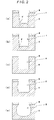
- 0012 That is, according to the inventors' study, when the temperature to which a semiconductor substrate K is heated is low, as shown in
Fig. 2(a) , a sub-trench H' is additionally formed at the side wall side of the bottom of a hole H or trench H which is formed by etching and it is therefore not possible to obtain an accurate etching shape. However, as the temperature to which the semiconductor substrate K is heated becomes gradually higher, as shown inFig. 2(b) , the formed sub-trench H' becomes gradually smaller, and finally, as shown inFig. 2(c) , the sub-trench H' is not formed. - 0013 Further, as the temperature to which the semiconductor substrate K is heated becomes gradually higher from the temperature at which the sub-trench H' is not formed, the etching becomes apt to proceed isotropically, and, as shown in
Figs. 2(d) and 2(e) , the side wall of the hole H or trench H is also etched. The atoms forming the semiconductor substrate K do not react with radicals and ions generated by generating plasma from an etching gas until the bonds between the atoms are broken. When the temperature of the semiconductor substrate K is higher, the bonds between the atoms are broken more easily and the atoms forming the semiconductor substrate K more easily react with radicals and ions generated by generating plasma from an etching gas, and therefore the etching caused by this reaction proceeds efficiently. It is noted that, among the above-mentioned materials which can form a semiconductor substrate K, particularly silicon carbide has a strong bond between silicon (Si) and carbon (C), but, when the temperature of the semiconductor substrate K is higher, the bond between them is broken more easily and the semiconductor substrate K can be easily etched. Therefore, as the temperature to which the semiconductor substrate K is heated becomes higher, the wide-gap semiconductor substrate K becomes apt to be etched isotropically and the side wall of the hole H or trench H becomes apt to be etched. It is noted that, comparingFigs. 2(d) and 2(e), Fig. 2(e) shows an etching shape obtained when the temperature to which the semiconductor substrate K is heated is higher. Further, inFig. 2 , the reference M indicates a mask. - 0014 The relationship between the temperature to which the semiconductor substrate was heated and etching shape was examined taking the above-described matters into consideration, and it was verified that, where the temperature to which the semiconductor substrate was heated was a temperature between 200°C and 400°C, when plasma etching was performed, the sub-trench H' was never formed in the bottom of the hole H or trench H, and, even though the sub-trench H' was formed therein, it was a very small one, and the side wall of the hole H or trench H was never etched, and, even though it was etched, it was etched very slightly. Therefore, heating the semiconductor substrate to a temperature between 200°C and 400°C enables the semiconductor substrate to be etched with high accuracy. It is noted that it is more preferable that the temperature to which the semiconductor substrate is heated is a temperature in the range of 300°C to 400°C.
- 0015 Thus, according to the plasma etching method of the present invention, it is possible to accurately etch a silicon carbide substrate because the silicon carbide substrate is heated to a temperature between 200°C and 400°C when plasma etching the silicon carbide substrate.
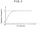
- 0016 By the way, as shown in
Fig. 3 , it takes a certain time to raise the temperature of a silicon carbide substrate from a temperature before heating T0 to a temperature for etching T1 (200°C ≤ T1 ≤ 400°C). Further, if an etching gas is supplied into the processing chamber and etching of a silicon carbide substrate is started before the temperature of the silicon carbide substrate reaches the etching temperature T1, because etching conditions vary due to the change of the temperature of the silicon carbide substrate until the temperature of the silicon carbide substrate reaches the etching temperature T1 after the start of the etching, problems occur that it is not possible to etch the silicon carbide substrate with high accuracy (for example, a sub-trench H' as shown inFig. 2(a) or Fig. 2(b) , which is formed by etching during a time period during which the temperature of the silicon carbide substrate is low, cannot be removed completely even by etching after the temperature of the silicon carbide substrate reaches the etching temperature T1), and that the etching rate is not uniform. - 0017 Therefore, by etching a silicon carbide substrate with a plasma generated form an etching gas while maintaining the temperature of the silicon carbide substrate at a temperature for etching after the silicon carbide substrate is heated in advance until the temperature thereof reaches the temperature for etching, it is possible to prevent the change of the temperature of the silicon carbide substrate after the start of the etching and thereby stabilize the etching. Therefore, it is possible to accurately etch the silicon carbide substrate and to prevent the etching rate from becoming non-uniform.
- 0018 It is noted that a configuration is possible in which, when heating the silicon carbide substrate to raise the temperature thereof to the temperature for etching, an inert gas is supplied into the processing chamber and plasma is generated from the inert gas, and a bias potential is applied to the platen, thereby making ions which are generated by the generation of plasma from the inert gas incident on the silicon carbide substrate to thereby heat the silicon carbide substrate. When thus configured, it is possible to raise the temperature of the silicon carbide substrate to a predetermined temperature while preventing etching by ion incidence. Further, the silicon carbide substrate can be heated only by generating plasma from an inert gas without newly providing heating means for heating the silicon carbide substrate.
- 0019 Further, in order to maintain the temperature of the silicon carbide substrate at a constant temperature, it is advantageous that the silicon carbide substrate is heated by incidence of ions which are generated by generating plasma from an etching gas.
- 0020 Besides, when heating the silicon carbide substrate, the silicon carbide substrate may be heated by a heater or by both ion incidence and a heater. Further, in a case where the temperature of the silicon carbide substrate rises too high, cooling of the silicon carbide substrate may be incorporated.
- 0022 As described above, according to the plasma etching method of the present invention, setting the temperature to which a silicon carbide substrate is heated to a temperature between 200°C and 400°C makes it possible to perform a highly accurate plasma etching.
- 0023
-
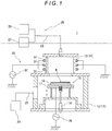
Fig. 1 is a sectional view showing a schematic configuration of an etching apparatus for performing a plasma etching method according to one embodiment of the present invention; -
Fig. 2 is a sectional view for explaining the relationship between etching shape of substrate and heating temperature; and -
Fig. 3 is a graph showing the relationship between temperature of substrate and heating time. - 0024 Hereinafter, a specific embodiment of the present invention will be described on the basis of the accompanying drawings. It is noted that the embodiment describes, as an example, a case where a silicon carbide substrate K is plasma etched by an
etching apparatus 1 shown inFig. 1 . Further, this silicon carbide substrate K has, for example, the crystal structure of 4H-SiC and has a silicon dioxide film as etching mask formed on the surface thereof, and the silicon dioxide film has a mask pattern of a predetermined shape formed thereon. - 0025 Initially, the
etching apparatus 1 will be described. Theetching apparatus 1 has, as shown inFig. 1 , aprocessing chamber 11 having a closed space, aplaten 15 which is disposed in theprocessing chamber 11 in such a manner that it can be freely lifted up and down and on which the silicon carbide substrate K is placed, alifting cylinder 18 for lifting up and down theplaten 15, anexhaust device 20 for reducing the pressure in theprocessing chamber 11, agas supply device 25 for supplying an etching gas and an inert gas into theprocessing chamber 11, aplasma generating device 30 for generating plasma from the etching gas and inert gas supplied into theprocessing chamber 11, and an RFpower supply unit 35 for supplying RF power to theplaten 15. - 0026 The
processing chamber 11 is configured by alower chamber 12 and anupper chamber 13 each having an inner space, the inner spaces communicating with each other, and theupper chamber 13 is formed to be smaller than thelower chamber 12. Theplaten 15 is configured by anupper member 16 on which the silicon carbide substrate K is placed and alower member 17 to which thelifting cylinder 18 is connected, and theplaten 15 is disposed in thelower chamber 12. - 0027 The
exhaust device 20 has anexhaust pipe 21 which is connected to a side surface of thelower chamber 12, and theexhaust device 20 exhausts the gas within theprocessing chamber 11 through theexhaust pipe 21 to thereby reduce the pressure in theprocessing chamber 11 to a predetermined pressure. - 0028 The
gas supply device 25 has an etchinggas supply section 26 supplying according to the invention, SF6 gas as etching gas, and an inertgas supply section 27 supplying an inert gas such as He gas, for example, and asupply pipe 28 one end of which is connected to the top surface of theupper chamber 13 and the other end of which is branched and connected to the etchinggas supply section 26 and the inertgas supply section 27. An etching gas is supplied into theprocessing chamber 11 from the etchinggas supply section 26 through thesupply pipe 28 and an inert gas is supplied into theprocessing chamber 11 from the inertgas supply section 27 through thesupply pipe 28. 0029 - The
plasma generating device 30 is configured by a plurality ofannular coils 31 which are provided on the outer peripheral portion of theupper chamber 13 in such a manner that they are aligned in the vertical direction, and an RFpower supply unit 32 for supplying RF power to thecoils 31. Plasma is generated from an etching gas and inert gas supplied into theupper chamber 13 by supplying RF power to thecoils 31 by means of the RFpower supply unit 32. The RFpower supply unit 35 supplies RF power to theplaten 15 to thereby generate a potential difference (bias potential) between theplaten 15 and the plasma, thereby making ions which are generated by generating plasma from the etching gas and the inert gas incident on the silicon carbide substrate K. - 0030 Next, a method of plasma etching a silicon carbide substrate K using the
etching apparatus 1 configured as described above will be described. - 0031 First, the silicon carbide substrate K is loaded into the
etching apparatus 1 and placed on theplaten 15, and the silicon carbide substrate K is heated until the temperature thereof reaches a temperature between 200°C and 400°C for etching (etching temperature). At this time, in theetching apparatus 1, an inert gas is supplied into theprocessing chamber 11 from the inertgas supply section 27, the pressure in theprocessing chamber 11 is reduced to a predetermined pressure by theexhaust device 20, and RF power is supplied to thecoils 31 and theplaten 15 by the RFpower supply units processing chamber 11 and ions generated by the generation of plasma are made incident on the silicon carbide substrate K and collide therewith due to the bias potential. Thereby, the silicon carbide substrate K is heated, and the temperature thereof rises and is balanced at the etching temperature in due course. - 0032 It is noted that whether the temperature of the silicon carbide substrate K reaches the etching temperature can be judged by the heating time of the silicon carbide substrate K or by measurement of temperature, for example. Further, because the silicon dioxide film which is an etching mask has a higher heat resistance than the resist, even though the silicon carbide substrate K is heated to a temperature between 200°C and 400°C, it is not possible that the silicon dioxide film is softened and the shape accuracy of the mask pattern thereof is therefore reduced.
- 0033 Once the temperature of the silicon carbide substrate K is balanced at the etching temperature, the silicon carbide substrate K is etched using the silicon dioxide film as mask. At this time, in the
etching apparatus 1, an etching gas is supplied into theprocessing chamber 11 from the etchinggas supply section 26, the pressure in theprocessing chamber 11 is reduced to a predetermined pressure by theexhaust device 20, and RF power is supplied to thecoils 31 and theplaten 15 by the RFpower supply units processing chamber 11 and the silicon carbide substrate K is etched by radicals and ions generated by the generation of plasma. Holes and/or trenches corresponding to the mask pattern of the silicon dioxide film are formed in the silicon carbide substrate K. - 0034 It is noted that, since, also when the silicon carbide substrate K is etched, the silicon carbide substrate K is heated by ions which are made incident thereon and collide therewith due to the bias potential, the temperature of the silicon carbide substrate K is maintained constant (at the etching temperature).
- 0035 By the way, as described above, in the embodiment, the silicon carbide substrate K is heated to a temperature between 200°C and 400°C for etching. The reason for this is that, as a result of the inventors' study, it was found that, when etching a silicon carbide substrate K having a strong interatomic bond, it is preferable to heat the silicon carbide substrate K to a temperature between 200°C and 400°C.
- 0036 That is, according to the inventors' study, when the temperature to which a silicon carbide substrate K is heated is low, as shown in
Fig. 2(a) , a sub-trench H' is additionally formed at the side wall side of the bottom of a hole H or trench H which is formed by etching and it is therefore not possible to obtain an accurate etching shape. However, as the temperature to which the silicon carbide substrate K is heated is increased gradually, as shown inFig. 2(b) , the formed sub-trench H' becomes gradually smaller, and finally, as shown inFig. 2(c) , the sub-trench H' is not formed. - 0037 Further, as the temperature to which the silicon carbide substrate K is heated is increased gradually from the temperature at which the sub-trench H' is not formed, the etching becomes apt to proceed isotropically, and as shown in
Figs. 2(d) and 2(e) , the side wall of the hole H or trench H is also etched. Although silicon (Si) and carbon (C) forming the silicon carbide substrate K do not react with radicals and ions generated by generating plasma from an etching gas until the bonds between them are broken, when the temperature of the silicon carbide substrate K is higher, the bonds between the silicon and the carbon are broken more easily and the silicon and the carbon more easily react with radicals and ions generated by generating plasma from an etching gas, and therefore the etching caused by this reaction proceeds efficiently. Therefore, as the temperature to which the silicon carbide substrate K is heated becomes higher, the silicon carbide substrate K becomes apt to be etched isotropically and the side wall of the hole H or trench H becomes apt to be etched. - 0038 The relationship between the temperature to which the silicon carbide substrate K was heated and etching shape was examined taking the above-described matters into consideration, and it was verified that, where the temperature to which the silicon carbide substrate K was heated was a temperature between 200°C and 400°C (more preferably, between 300°C and 400°C), when the silicon carbide substrate K was etched, the sub-trench H' was never formed in the bottom of the hole H or trench H, and, the side wall of the hole H or trench H was never etched. Therefore, heating the silicon carbide substrate K to a temperature between 200°C and 400°C (more preferably, between 300°C and 400°C) makes it possible to etch the silicon carbide substrate K with high accuracy.
- 0039 Thus, according to the plasma etching method of the embodiment, it is possible to accurately etch a silicon carbide substrate K because the silicon carbide substrate K is heated to a temperature between 200°C and 400°C when plasma etching the silicon carbide substrate K.
- 0040 Further, according to the invention, the etching is started after the temperature of the silicon carbide substrate K reaches the etching temperature. The reason for this is that, because, as shown in
Fig. 3 , it takes a certain time to raise the temperature of the silicon carbide substrate K from a temperature before heating T0 to the etching temperature T1 (200°C ≤ T1 ≤ 400°C), if the etching of the silicon carbide substrate K is started before the temperature thereof reaches the etching temperature T1, problems occur that, because etching conditions vary due to the change of the temperature of the silicon carbide substrate K until the temperature of the silicon carbide substrate K reaches the etching temperature T1 after the start of the etching, it is not possible to etch the silicon carbide substrate K with high accuracy (for example, a sub-trench H' as shown inFig. 2(a) or Fig. 2(b) , which is formed by etching during a time period during which the temperature of the silicon carbide substrate K is low, cannot be removed completely even by etching after the temperature of the silicon carbide substrate K reaches the etching temperature T1), and that the etching rate is not uniform. - 0041 Therefore, by starting the etching after the temperature of the silicon carbide substrate K reaches the etching temperature T1, it is possible to prevent the change of the temperature of the silicon carbide substrate K after the start of the etching and thereby stabilize the etching. Therefore, it is possible to accurately etch the silicon carbide substrate K and to prevent the etching rate from becoming non-uniform.
- 0042 Further, since the silicon carbide substrate K is heated by making ions which are generated by generating plasma from the inert gas incident on the silicon carbide substrate K and collide therewith, it is possible to raise the temperature of the silicon carbide substrate K while preventing etching caused by ion incidence. Further, it is possible to heat the silicon carbide substrate K only by generating plasma from an inert gas without providing a heating mechanism for heating the silicon carbide substrate K on the
processing chamber 11. - 0043 In this connection, when etching a silicon carbide substrate K having a silicon dioxide film as mask formed on the surface thereof using the plasma etching method of the invention, an accurate etching shape as shown in
Fig. 2(c) was obtained without a sub-trench H' as shown inFig. 2(a) or Fig. 2(b) being formed and without the side wall being etched as shown inFig. 2(d) or Fig. 2(e) . It is noted that the processing conditions when heating the silicon carbide substrate K by the generation of plasma from an inert gas and thereby raising the temperature of the silicon carbide substrate K to an etching temperature between 200°C and 400°C were that the supply flow rate of He gas as inert gas was 50 sccm, the pressure in theprocessing chamber 11 was 3 Pa, the RF power to be supplied to thecoils 31 was 2.5 kW, and the RF power to be supplied to theplaten 15 was 700 W. Further, the processing conditions when etching the silicon carbide substrate K after the temperature thereof reached the etching temperature were that the supply flow rate of SF6 gas as etching gas was 50 sccm, the pressure in theprocessing chamber 11 was 3 Pa, the RF power to be supplied to thecoils 31 was 2.5 kW, and the RF power to be supplied to theplaten 15 was 700 W. Further, the etching temperature for the silicon carbide substrate K at this time was about 400°C. - 0045 Although, in the above embodiment, the temperature of the silicon carbide substrate K is raised by making ions which are generated by generating of plasma from an inert gas incident on the silicon carbide substrate K and collide therewith, the silicon carbide substrate K can be heated by any method. For example, a configuration is possible in which a heater is embedded in the
platen 15 and the silicon carbide substrate K is heated by the heater or by both the ion incidence and the heater. Further, in a case where the temperature of the silicon carbide substrate K is raised above 400°C by heating, it is advantageous to control the temperature of the silicon carbide substrate K in the range of 200°C to 400°C in combination with cooling of the silicon carbide substrate K. - 0046 Furthermore, although, for the substrate to be etched K, the silicon carbide substrate having the crystal structure of 4H-SiC is given as an example, the substrate to be etched K may be a silicon carbide substrate having a crystal structure other than 4H-SiC. Further, for the etching mask on the silicon carbide substrate K, instead of the above-mentioned silicon dioxide film, a nickel film can be employed, according to the invention.
- 0047 Furthermore, although, in the above embodiment, the plasma etching method of the present invention is performed using the
etching apparatus 1, an etching apparatus having a different configuration can be used for performing this plasma etching method. - 0048
- 1
- Etching apparatus
- 11
- Processing chamber
- 15
- Platen
- 20
- Exhaust device
- 25
- Gas supply device
- 26
- Etching gas supply section
- 27
- Inert gas supply section
- 30
- Plasma generating device
- 31
- Coil
- 32
- RF power supply unit
- 35
- RF power supply unit
- K
- Silicon carbide substrate (wide-gap semiconductor substrate)
Claims (2)
- A plasma etching method in whichan etching gas is supplied into a processing chamber (11) and plasma is generated from the etching gas anda bias potential is applied to a platen (15) which is disposed in the processing chamber (11) and on which a silicon carbide substrate (K) is placed, thereby plasma etching the silicon carbide substrate (K) on the platen (15), with a silicon dioxide film or a nickel film as etching mask formed on the surface of the silicon carbide substrate (K),wherein SF6 gas is used as the etching gas,wherein the silicon carbide substrate (K) is heated to a temperature between 200°C and 400°C for etching,and wherein, after the silicon carbide substrate (K) is heated in advance until the temperature thereof reaches the temperature for etching between 200°C and 400°C, the silicon carbide substrate (K) is etched by the plasma generated from the etching gas while maintaining the temperature of the silicon carbide substrate (K) at the temperature for etching between 200°C and 400°C,and whereinwhen etching the silicon carbide substrate (K) having the silicon dioxide film or nickel film as etching mask formed on the surface thereof using the plasma generated from the etching gas while maintaining the temperature of the silicon carbide substrate (K) at the temperature for etching between 200°C and 400°C an etching shape of a hole (H) or trench (H) formed by etching is obtained without a sub-trench being formed at a bottom of the hole (H) or trench (H) and without the side wall of the hole (H) or trench (H) being etched isotropically.
- The plasma etching method according to claim 1, characterized in thatwhen the silicon carbide substrate (K) is heated to raise the temperature thereof to the temperature for etching between 200°C and 400°C,the silicon carbide substrate (K) is heated by supplying an inert gas into the processing chamber (11) and generating plasma from the inert gas, andapplying a bias potential to the platen (15), andthereby making ions which are generated by the generation of plasma from the inert gas incident on the silicon carbide substrate (K) to thereby heat the silicon carbide substrate (K).
Applications Claiming Priority (2)
| Application Number | Priority Date | Filing Date | Title |
|---|---|---|---|
| JP2009246096A JP5179455B2 (en) | 2009-10-27 | 2009-10-27 | Plasma etching method |
| PCT/JP2010/065203 WO2011052296A1 (en) | 2009-10-27 | 2010-09-06 | Plasma etching method |
Publications (3)
| Publication Number | Publication Date |
|---|---|
| EP2495757A1 EP2495757A1 (en) | 2012-09-05 |
| EP2495757A4 EP2495757A4 (en) | 2013-02-20 |
| EP2495757B1 true EP2495757B1 (en) | 2020-04-22 |
Family
ID=43921726
Family Applications (1)
| Application Number | Title | Priority Date | Filing Date |
|---|---|---|---|
| EP10826431.8A Active EP2495757B1 (en) | 2009-10-27 | 2010-09-06 | Plasma etching method |
Country Status (6)
| Country | Link |
|---|---|
| US (1) | US8673781B2 (en) |
| EP (1) | EP2495757B1 (en) |
| JP (1) | JP5179455B2 (en) |
| KR (1) | KR101861709B1 (en) |
| CN (1) | CN102473630A (en) |
| WO (1) | WO2011052296A1 (en) |
Families Citing this family (9)
| Publication number | Priority date | Publication date | Assignee | Title |
|---|---|---|---|---|
| FR2934709B1 (en) * | 2008-08-01 | 2010-09-10 | Commissariat Energie Atomique | THERMAL EXCHANGE STRUCTURE AND COOLING DEVICE HAVING SUCH A STRUCTURE. |
| WO2012008179A1 (en) * | 2010-07-12 | 2012-01-19 | 住友精密工業株式会社 | Etching method |
| JP5658110B2 (en) * | 2011-08-29 | 2015-01-21 | パナソニックIpマネジメント株式会社 | Dry etching method |
| KR101904126B1 (en) | 2011-09-05 | 2018-10-04 | 에스피피 테크놀로지스 컴퍼니 리미티드 | Plasma etching method |
| JP5877982B2 (en) * | 2011-09-22 | 2016-03-08 | Sppテクノロジーズ株式会社 | Plasma etching method |
| JP5888027B2 (en) * | 2012-03-14 | 2016-03-16 | 富士通株式会社 | Manufacturing method of semiconductor device |
| US20140342569A1 (en) * | 2013-05-16 | 2014-11-20 | Applied Materials, Inc. | Near surface etch selectivity enhancement |
| JP5874687B2 (en) * | 2013-05-31 | 2016-03-02 | 豊田合成株式会社 | Manufacturing method of semiconductor device |
| JP2017005177A (en) * | 2015-06-12 | 2017-01-05 | 株式会社日立ハイテクノロジーズ | Plasma processing device and plasma treatment method |
Citations (1)
| Publication number | Priority date | Publication date | Assignee | Title |
|---|---|---|---|---|
| US20070207614A1 (en) * | 2006-03-01 | 2007-09-06 | Eudyna Devices Inc. | Semiconductor device and method of manufacturing the same |
Family Cites Families (17)
| Publication number | Priority date | Publication date | Assignee | Title |
|---|---|---|---|---|
| JPH07105441B2 (en) * | 1992-11-30 | 1995-11-13 | 日本電気株式会社 | Method for manufacturing semiconductor device |
| JPH088232A (en) * | 1994-06-22 | 1996-01-12 | Sony Corp | Plasma treatment method |
| US5571374A (en) * | 1995-10-02 | 1996-11-05 | Motorola | Method of etching silicon carbide |
| JPH10303185A (en) | 1997-04-26 | 1998-11-13 | Anelva Corp | Etching apparatus and etching method |
| JPH11162958A (en) * | 1997-09-16 | 1999-06-18 | Tokyo Electron Ltd | Plasma treating device and plasma treating method |
| JP2001144075A (en) | 1999-11-15 | 2001-05-25 | Matsushita Electric Ind Co Ltd | Plasma treatment device |
| US6475889B1 (en) * | 2000-04-11 | 2002-11-05 | Cree, Inc. | Method of forming vias in silicon carbide and resulting devices and circuits |
| US6670278B2 (en) * | 2001-03-30 | 2003-12-30 | Lam Research Corporation | Method of plasma etching of silicon carbide |
| JP2003069154A (en) * | 2001-06-11 | 2003-03-07 | Sharp Corp | Semiconductor laser element and manufacturing method thereof |
| JP2003273084A (en) * | 2002-03-15 | 2003-09-26 | Seiko Epson Corp | Atmospheric pressure plasma apparatus and atmospheric pressure plasma processing method, device, and device manufacturing method |
| JP4030982B2 (en) | 2004-05-10 | 2008-01-09 | ユーディナデバイス株式会社 | Semiconductor device and manufacturing method of semiconductor device |
| US7465670B2 (en) * | 2005-03-28 | 2008-12-16 | Tokyo Electron Limited | Plasma etching method, plasma etching apparatus, control program and computer storage medium with enhanced selectivity |
| JP4859474B2 (en) * | 2006-02-15 | 2012-01-25 | 三菱重工業株式会社 | Plasma processing method and plasma processing apparatus |
| JP5135885B2 (en) | 2007-05-24 | 2013-02-06 | 富士電機株式会社 | Method for manufacturing silicon carbide semiconductor device |
| JP5072082B2 (en) * | 2007-09-07 | 2012-11-14 | 株式会社アルバック | Dry etching method |
| JP5309587B2 (en) | 2008-02-07 | 2013-10-09 | 富士電機株式会社 | Trench etching method for silicon carbide semiconductor substrate |
| JP2009194194A (en) * | 2008-02-15 | 2009-08-27 | Sumitomo Precision Prod Co Ltd | Method of plasma treatment |
-
2009
- 2009-10-27 JP JP2009246096A patent/JP5179455B2/en active Active
-
2010
- 2010-09-06 CN CN2010800266927A patent/CN102473630A/en active Pending
- 2010-09-06 US US13/318,279 patent/US8673781B2/en active Active
- 2010-09-06 EP EP10826431.8A patent/EP2495757B1/en active Active
- 2010-09-06 KR KR1020117023438A patent/KR101861709B1/en active IP Right Grant
- 2010-09-06 WO PCT/JP2010/065203 patent/WO2011052296A1/en active Application Filing
Patent Citations (1)
| Publication number | Priority date | Publication date | Assignee | Title |
|---|---|---|---|---|
| US20070207614A1 (en) * | 2006-03-01 | 2007-09-06 | Eudyna Devices Inc. | Semiconductor device and method of manufacturing the same |
Also Published As
| Publication number | Publication date |
|---|---|
| CN102473630A (en) | 2012-05-23 |
| JP5179455B2 (en) | 2013-04-10 |
| EP2495757A1 (en) | 2012-09-05 |
| US20120052688A1 (en) | 2012-03-01 |
| KR20120073160A (en) | 2012-07-04 |
| JP2011096700A (en) | 2011-05-12 |
| WO2011052296A1 (en) | 2011-05-05 |
| EP2495757A4 (en) | 2013-02-20 |
| KR101861709B1 (en) | 2018-05-28 |
| US8673781B2 (en) | 2014-03-18 |
Similar Documents
| Publication | Publication Date | Title |
|---|---|---|
| EP2495757B1 (en) | Plasma etching method | |
| JP5762491B2 (en) | Etching method | |
| EP2755230B1 (en) | Plasma etching method | |
| JP2008311541A (en) | Manufacturing method of silicon carbide semiconductor substrate | |
| US9299576B2 (en) | Method of plasma etching a trench in a semiconductor substrate | |
| JP2010129764A (en) | Susceptor, semiconductor manufacturing apparatus, and semiconductor manufacturing method | |
| JP5877982B2 (en) | Plasma etching method | |
| EP3035371A1 (en) | Silicon carbide semiconductor substrate, method for producing same, and method for producing silicon carbide semiconductor device | |
| US7718515B2 (en) | Method for fabricating semiconductor device | |
| WO2018066173A1 (en) | Silicon carbide epitaxial substrate, and method for manufacturing silicon carbide semiconductor device | |
| JP2012231081A (en) | Semiconductor device manufacturing method | |
| JP6233555B1 (en) | Silicon carbide epitaxial substrate and method for manufacturing silicon carbide semiconductor device | |
| JP6567487B2 (en) | Plasma etching method | |
| US20220216116A1 (en) | Temperature distribution evaluation method, temperature distribution evaluation device, and soaking range evaluation method | |
| JP6130313B2 (en) | Plasma etching method | |
| JP2012054616A (en) | Plasma etching method | |
| CN104599952A (en) | Method for removing etch damage layer formed in etching of silicon carbide plasma | |
| JP2012054616A5 (en) | ||
| US20080206924A1 (en) | Method for fabtricating semiconductor device | |
| CN114351253B (en) | Method and apparatus for producing silicon carbide single crystal, and silicon carbide single crystal ingot | |
| Niebelschutz et al. | Isotropic dry-etching of SiC for AlGaN/GaN MEMS fabrication |
Legal Events
| Date | Code | Title | Description |
|---|---|---|---|
| PUAI | Public reference made under article 153(3) epc to a published international application that has entered the european phase |
Free format text: ORIGINAL CODE: 0009012 |
|
| 17P | Request for examination filed |
Effective date: 20120229 |
|
| AK | Designated contracting states |
Kind code of ref document: A1 Designated state(s): AL AT BE BG CH CY CZ DE DK EE ES FI FR GB GR HR HU IE IS IT LI LT LU LV MC MK MT NL NO PL PT RO SE SI SK SM TR |
|
| DAX | Request for extension of the european patent (deleted) | ||
| A4 | Supplementary search report drawn up and despatched |
Effective date: 20130123 |
|
| RIC1 | Information provided on ipc code assigned before grant |
Ipc: H01L 21/3065 20060101AFI20130114BHEP Ipc: H01L 21/04 20060101ALI20130114BHEP |
|
| RAP1 | Party data changed (applicant data changed or rights of an application transferred) |
Owner name: SPP TECHNOLOGIES CO., LTD. |
|
| STAA | Information on the status of an ep patent application or granted ep patent |
Free format text: STATUS: EXAMINATION IS IN PROGRESS |
|
| 17Q | First examination report despatched |
Effective date: 20181015 |
|
| GRAP | Despatch of communication of intention to grant a patent |
Free format text: ORIGINAL CODE: EPIDOSNIGR1 |
|
| STAA | Information on the status of an ep patent application or granted ep patent |
Free format text: STATUS: GRANT OF PATENT IS INTENDED |
|
| INTG | Intention to grant announced |
Effective date: 20191122 |
|
| GRAS | Grant fee paid |
Free format text: ORIGINAL CODE: EPIDOSNIGR3 |
|
| GRAA | (expected) grant |
Free format text: ORIGINAL CODE: 0009210 |
|
| STAA | Information on the status of an ep patent application or granted ep patent |
Free format text: STATUS: THE PATENT HAS BEEN GRANTED |
|
| AK | Designated contracting states |
Kind code of ref document: B1 Designated state(s): AL AT BE BG CH CY CZ DE DK EE ES FI FR GB GR HR HU IE IS IT LI LT LU LV MC MK MT NL NO PL PT RO SE SI SK SM TR |
|
| REG | Reference to a national code |
Ref country code: GB Ref legal event code: FG4D |
|
| REG | Reference to a national code |
Ref country code: CH Ref legal event code: EP |
|
| REG | Reference to a national code |
Ref country code: DE Ref legal event code: R096 Ref document number: 602010064038 Country of ref document: DE |
|
| REG | Reference to a national code |
Ref country code: IE Ref legal event code: FG4D |
|
| REG | Reference to a national code |
Ref country code: AT Ref legal event code: REF Ref document number: 1261244 Country of ref document: AT Kind code of ref document: T Effective date: 20200515 |
|
| REG | Reference to a national code |
Ref country code: LT Ref legal event code: MG4D |
|
| REG | Reference to a national code |
Ref country code: NL Ref legal event code: MP Effective date: 20200422 |
|
| PG25 | Lapsed in a contracting state [announced via postgrant information from national office to epo] |
Ref country code: IS Free format text: LAPSE BECAUSE OF FAILURE TO SUBMIT A TRANSLATION OF THE DESCRIPTION OR TO PAY THE FEE WITHIN THE PRESCRIBED TIME-LIMIT Effective date: 20200822 Ref country code: GR Free format text: LAPSE BECAUSE OF FAILURE TO SUBMIT A TRANSLATION OF THE DESCRIPTION OR TO PAY THE FEE WITHIN THE PRESCRIBED TIME-LIMIT Effective date: 20200723 Ref country code: NO Free format text: LAPSE BECAUSE OF FAILURE TO SUBMIT A TRANSLATION OF THE DESCRIPTION OR TO PAY THE FEE WITHIN THE PRESCRIBED TIME-LIMIT Effective date: 20200722 Ref country code: FI Free format text: LAPSE BECAUSE OF FAILURE TO SUBMIT A TRANSLATION OF THE DESCRIPTION OR TO PAY THE FEE WITHIN THE PRESCRIBED TIME-LIMIT Effective date: 20200422 Ref country code: NL Free format text: LAPSE BECAUSE OF FAILURE TO SUBMIT A TRANSLATION OF THE DESCRIPTION OR TO PAY THE FEE WITHIN THE PRESCRIBED TIME-LIMIT Effective date: 20200422 Ref country code: SE Free format text: LAPSE BECAUSE OF FAILURE TO SUBMIT A TRANSLATION OF THE DESCRIPTION OR TO PAY THE FEE WITHIN THE PRESCRIBED TIME-LIMIT Effective date: 20200422 Ref country code: PT Free format text: LAPSE BECAUSE OF FAILURE TO SUBMIT A TRANSLATION OF THE DESCRIPTION OR TO PAY THE FEE WITHIN THE PRESCRIBED TIME-LIMIT Effective date: 20200824 Ref country code: LT Free format text: LAPSE BECAUSE OF FAILURE TO SUBMIT A TRANSLATION OF THE DESCRIPTION OR TO PAY THE FEE WITHIN THE PRESCRIBED TIME-LIMIT Effective date: 20200422 |
|
| REG | Reference to a national code |
Ref country code: AT Ref legal event code: MK05 Ref document number: 1261244 Country of ref document: AT Kind code of ref document: T Effective date: 20200422 |
|
| PG25 | Lapsed in a contracting state [announced via postgrant information from national office to epo] |
Ref country code: BG Free format text: LAPSE BECAUSE OF FAILURE TO SUBMIT A TRANSLATION OF THE DESCRIPTION OR TO PAY THE FEE WITHIN THE PRESCRIBED TIME-LIMIT Effective date: 20200722 Ref country code: LV Free format text: LAPSE BECAUSE OF FAILURE TO SUBMIT A TRANSLATION OF THE DESCRIPTION OR TO PAY THE FEE WITHIN THE PRESCRIBED TIME-LIMIT Effective date: 20200422 Ref country code: HR Free format text: LAPSE BECAUSE OF FAILURE TO SUBMIT A TRANSLATION OF THE DESCRIPTION OR TO PAY THE FEE WITHIN THE PRESCRIBED TIME-LIMIT Effective date: 20200422 |
|
| PG25 | Lapsed in a contracting state [announced via postgrant information from national office to epo] |
Ref country code: AL Free format text: LAPSE BECAUSE OF FAILURE TO SUBMIT A TRANSLATION OF THE DESCRIPTION OR TO PAY THE FEE WITHIN THE PRESCRIBED TIME-LIMIT Effective date: 20200422 |
|
| REG | Reference to a national code |
Ref country code: DE Ref legal event code: R097 Ref document number: 602010064038 Country of ref document: DE |
|
| PG25 | Lapsed in a contracting state [announced via postgrant information from national office to epo] |
Ref country code: AT Free format text: LAPSE BECAUSE OF FAILURE TO SUBMIT A TRANSLATION OF THE DESCRIPTION OR TO PAY THE FEE WITHIN THE PRESCRIBED TIME-LIMIT Effective date: 20200422 Ref country code: EE Free format text: LAPSE BECAUSE OF FAILURE TO SUBMIT A TRANSLATION OF THE DESCRIPTION OR TO PAY THE FEE WITHIN THE PRESCRIBED TIME-LIMIT Effective date: 20200422 Ref country code: SM Free format text: LAPSE BECAUSE OF FAILURE TO SUBMIT A TRANSLATION OF THE DESCRIPTION OR TO PAY THE FEE WITHIN THE PRESCRIBED TIME-LIMIT Effective date: 20200422 Ref country code: DK Free format text: LAPSE BECAUSE OF FAILURE TO SUBMIT A TRANSLATION OF THE DESCRIPTION OR TO PAY THE FEE WITHIN THE PRESCRIBED TIME-LIMIT Effective date: 20200422 Ref country code: CZ Free format text: LAPSE BECAUSE OF FAILURE TO SUBMIT A TRANSLATION OF THE DESCRIPTION OR TO PAY THE FEE WITHIN THE PRESCRIBED TIME-LIMIT Effective date: 20200422 Ref country code: IT Free format text: LAPSE BECAUSE OF FAILURE TO SUBMIT A TRANSLATION OF THE DESCRIPTION OR TO PAY THE FEE WITHIN THE PRESCRIBED TIME-LIMIT Effective date: 20200422 Ref country code: RO Free format text: LAPSE BECAUSE OF FAILURE TO SUBMIT A TRANSLATION OF THE DESCRIPTION OR TO PAY THE FEE WITHIN THE PRESCRIBED TIME-LIMIT Effective date: 20200422 Ref country code: ES Free format text: LAPSE BECAUSE OF FAILURE TO SUBMIT A TRANSLATION OF THE DESCRIPTION OR TO PAY THE FEE WITHIN THE PRESCRIBED TIME-LIMIT Effective date: 20200422 |
|
| PG25 | Lapsed in a contracting state [announced via postgrant information from national office to epo] |
Ref country code: PL Free format text: LAPSE BECAUSE OF FAILURE TO SUBMIT A TRANSLATION OF THE DESCRIPTION OR TO PAY THE FEE WITHIN THE PRESCRIBED TIME-LIMIT Effective date: 20200422 Ref country code: SK Free format text: LAPSE BECAUSE OF FAILURE TO SUBMIT A TRANSLATION OF THE DESCRIPTION OR TO PAY THE FEE WITHIN THE PRESCRIBED TIME-LIMIT Effective date: 20200422 |
|
| PLBE | No opposition filed within time limit |
Free format text: ORIGINAL CODE: 0009261 |
|
| STAA | Information on the status of an ep patent application or granted ep patent |
Free format text: STATUS: NO OPPOSITION FILED WITHIN TIME LIMIT |
|
| 26N | No opposition filed |
Effective date: 20210125 |
|
| PG25 | Lapsed in a contracting state [announced via postgrant information from national office to epo] |
Ref country code: MC Free format text: LAPSE BECAUSE OF FAILURE TO SUBMIT A TRANSLATION OF THE DESCRIPTION OR TO PAY THE FEE WITHIN THE PRESCRIBED TIME-LIMIT Effective date: 20200422 |
|
| REG | Reference to a national code |
Ref country code: CH Ref legal event code: PL |
|
| PG25 | Lapsed in a contracting state [announced via postgrant information from national office to epo] |
Ref country code: SI Free format text: LAPSE BECAUSE OF FAILURE TO SUBMIT A TRANSLATION OF THE DESCRIPTION OR TO PAY THE FEE WITHIN THE PRESCRIBED TIME-LIMIT Effective date: 20200422 |
|
| REG | Reference to a national code |
Ref country code: BE Ref legal event code: MM Effective date: 20200930 |
|
| PG25 | Lapsed in a contracting state [announced via postgrant information from national office to epo] |
Ref country code: LU Free format text: LAPSE BECAUSE OF NON-PAYMENT OF DUE FEES Effective date: 20200906 |
|
| PG25 | Lapsed in a contracting state [announced via postgrant information from national office to epo] |
Ref country code: IE Free format text: LAPSE BECAUSE OF NON-PAYMENT OF DUE FEES Effective date: 20200906 Ref country code: LI Free format text: LAPSE BECAUSE OF NON-PAYMENT OF DUE FEES Effective date: 20200930 Ref country code: BE Free format text: LAPSE BECAUSE OF NON-PAYMENT OF DUE FEES Effective date: 20200930 Ref country code: CH Free format text: LAPSE BECAUSE OF NON-PAYMENT OF DUE FEES Effective date: 20200930 |
|
| PG25 | Lapsed in a contracting state [announced via postgrant information from national office to epo] |
Ref country code: TR Free format text: LAPSE BECAUSE OF FAILURE TO SUBMIT A TRANSLATION OF THE DESCRIPTION OR TO PAY THE FEE WITHIN THE PRESCRIBED TIME-LIMIT Effective date: 20200422 Ref country code: MT Free format text: LAPSE BECAUSE OF FAILURE TO SUBMIT A TRANSLATION OF THE DESCRIPTION OR TO PAY THE FEE WITHIN THE PRESCRIBED TIME-LIMIT Effective date: 20200422 Ref country code: CY Free format text: LAPSE BECAUSE OF FAILURE TO SUBMIT A TRANSLATION OF THE DESCRIPTION OR TO PAY THE FEE WITHIN THE PRESCRIBED TIME-LIMIT Effective date: 20200422 |
|
| PG25 | Lapsed in a contracting state [announced via postgrant information from national office to epo] |
Ref country code: MK Free format text: LAPSE BECAUSE OF FAILURE TO SUBMIT A TRANSLATION OF THE DESCRIPTION OR TO PAY THE FEE WITHIN THE PRESCRIBED TIME-LIMIT Effective date: 20200422 |
|
| PGFP | Annual fee paid to national office [announced via postgrant information from national office to epo] |
Ref country code: GB Payment date: 20230727 Year of fee payment: 14 |
|
| PGFP | Annual fee paid to national office [announced via postgrant information from national office to epo] |
Ref country code: FR Payment date: 20230808 Year of fee payment: 14 Ref country code: DE Payment date: 20230802 Year of fee payment: 14 |