EP2495433B1 - Éolienne et procédé pour lever un bras de couple de boîte de vitesses - Google Patents
Éolienne et procédé pour lever un bras de couple de boîte de vitesses Download PDFInfo
- Publication number
- EP2495433B1 EP2495433B1 EP11382054.2A EP11382054A EP2495433B1 EP 2495433 B1 EP2495433 B1 EP 2495433B1 EP 11382054 A EP11382054 A EP 11382054A EP 2495433 B1 EP2495433 B1 EP 2495433B1
- Authority
- EP
- European Patent Office
- Prior art keywords
- torque arm
- gearbox
- support structure
- wind turbine
- rod
- Prior art date
- Legal status (The legal status is an assumption and is not a legal conclusion. Google has not performed a legal analysis and makes no representation as to the accuracy of the status listed.)
- Active
Links
- 238000000034 method Methods 0.000 title claims description 22
- 238000013016 damping Methods 0.000 claims description 29
- 230000000087 stabilizing effect Effects 0.000 description 7
- 230000005540 biological transmission Effects 0.000 description 2
- 230000013011 mating Effects 0.000 description 2
- 238000006073 displacement reaction Methods 0.000 description 1
- 230000005611 electricity Effects 0.000 description 1
- 238000012423 maintenance Methods 0.000 description 1
- 238000012986 modification Methods 0.000 description 1
- 230000004048 modification Effects 0.000 description 1
Images


Classifications
-
- F—MECHANICAL ENGINEERING; LIGHTING; HEATING; WEAPONS; BLASTING
- F16—ENGINEERING ELEMENTS AND UNITS; GENERAL MEASURES FOR PRODUCING AND MAINTAINING EFFECTIVE FUNCTIONING OF MACHINES OR INSTALLATIONS; THERMAL INSULATION IN GENERAL
- F16H—GEARING
- F16H57/00—General details of gearing
- F16H57/02—Gearboxes; Mounting gearing therein
- F16H57/025—Support of gearboxes, e.g. torque arms, or attachment to other devices
-
- F—MECHANICAL ENGINEERING; LIGHTING; HEATING; WEAPONS; BLASTING
- F03—MACHINES OR ENGINES FOR LIQUIDS; WIND, SPRING, OR WEIGHT MOTORS; PRODUCING MECHANICAL POWER OR A REACTIVE PROPULSIVE THRUST, NOT OTHERWISE PROVIDED FOR
- F03D—WIND MOTORS
- F03D80/00—Details, components or accessories not provided for in groups F03D1/00 - F03D17/00
- F03D80/50—Maintenance or repair
-
- F—MECHANICAL ENGINEERING; LIGHTING; HEATING; WEAPONS; BLASTING
- F03—MACHINES OR ENGINES FOR LIQUIDS; WIND, SPRING, OR WEIGHT MOTORS; PRODUCING MECHANICAL POWER OR A REACTIVE PROPULSIVE THRUST, NOT OTHERWISE PROVIDED FOR
- F03D—WIND MOTORS
- F03D80/00—Details, components or accessories not provided for in groups F03D1/00 - F03D17/00
- F03D80/70—Bearing or lubricating arrangements
-
- F—MECHANICAL ENGINEERING; LIGHTING; HEATING; WEAPONS; BLASTING
- F05—INDEXING SCHEMES RELATING TO ENGINES OR PUMPS IN VARIOUS SUBCLASSES OF CLASSES F01-F04
- F05B—INDEXING SCHEME RELATING TO WIND, SPRING, WEIGHT, INERTIA OR LIKE MOTORS, TO MACHINES OR ENGINES FOR LIQUIDS COVERED BY SUBCLASSES F03B, F03D AND F03G
- F05B2230/00—Manufacture
- F05B2230/60—Assembly methods
- F05B2230/61—Assembly methods using auxiliary equipment for lifting or holding
-
- F—MECHANICAL ENGINEERING; LIGHTING; HEATING; WEAPONS; BLASTING
- F05—INDEXING SCHEMES RELATING TO ENGINES OR PUMPS IN VARIOUS SUBCLASSES OF CLASSES F01-F04
- F05B—INDEXING SCHEME RELATING TO WIND, SPRING, WEIGHT, INERTIA OR LIKE MOTORS, TO MACHINES OR ENGINES FOR LIQUIDS COVERED BY SUBCLASSES F03B, F03D AND F03G
- F05B2230/00—Manufacture
- F05B2230/70—Disassembly methods
-
- F—MECHANICAL ENGINEERING; LIGHTING; HEATING; WEAPONS; BLASTING
- F05—INDEXING SCHEMES RELATING TO ENGINES OR PUMPS IN VARIOUS SUBCLASSES OF CLASSES F01-F04
- F05B—INDEXING SCHEME RELATING TO WIND, SPRING, WEIGHT, INERTIA OR LIKE MOTORS, TO MACHINES OR ENGINES FOR LIQUIDS COVERED BY SUBCLASSES F03B, F03D AND F03G
- F05B2230/00—Manufacture
- F05B2230/80—Repairing, retrofitting or upgrading methods
-
- F—MECHANICAL ENGINEERING; LIGHTING; HEATING; WEAPONS; BLASTING
- F05—INDEXING SCHEMES RELATING TO ENGINES OR PUMPS IN VARIOUS SUBCLASSES OF CLASSES F01-F04
- F05B—INDEXING SCHEME RELATING TO WIND, SPRING, WEIGHT, INERTIA OR LIKE MOTORS, TO MACHINES OR ENGINES FOR LIQUIDS COVERED BY SUBCLASSES F03B, F03D AND F03G
- F05B2240/00—Components
- F05B2240/50—Bearings
-
- F—MECHANICAL ENGINEERING; LIGHTING; HEATING; WEAPONS; BLASTING
- F05—INDEXING SCHEMES RELATING TO ENGINES OR PUMPS IN VARIOUS SUBCLASSES OF CLASSES F01-F04
- F05B—INDEXING SCHEME RELATING TO WIND, SPRING, WEIGHT, INERTIA OR LIKE MOTORS, TO MACHINES OR ENGINES FOR LIQUIDS COVERED BY SUBCLASSES F03B, F03D AND F03G
- F05B2260/00—Function
- F05B2260/96—Preventing, counteracting or reducing vibration or noise
- F05B2260/964—Preventing, counteracting or reducing vibration or noise by damping means
-
- Y—GENERAL TAGGING OF NEW TECHNOLOGICAL DEVELOPMENTS; GENERAL TAGGING OF CROSS-SECTIONAL TECHNOLOGIES SPANNING OVER SEVERAL SECTIONS OF THE IPC; TECHNICAL SUBJECTS COVERED BY FORMER USPC CROSS-REFERENCE ART COLLECTIONS [XRACs] AND DIGESTS
- Y02—TECHNOLOGIES OR APPLICATIONS FOR MITIGATION OR ADAPTATION AGAINST CLIMATE CHANGE
- Y02E—REDUCTION OF GREENHOUSE GAS [GHG] EMISSIONS, RELATED TO ENERGY GENERATION, TRANSMISSION OR DISTRIBUTION
- Y02E10/00—Energy generation through renewable energy sources
- Y02E10/70—Wind energy
- Y02E10/72—Wind turbines with rotation axis in wind direction
-
- Y—GENERAL TAGGING OF NEW TECHNOLOGICAL DEVELOPMENTS; GENERAL TAGGING OF CROSS-SECTIONAL TECHNOLOGIES SPANNING OVER SEVERAL SECTIONS OF THE IPC; TECHNICAL SUBJECTS COVERED BY FORMER USPC CROSS-REFERENCE ART COLLECTIONS [XRACs] AND DIGESTS
- Y02—TECHNOLOGIES OR APPLICATIONS FOR MITIGATION OR ADAPTATION AGAINST CLIMATE CHANGE
- Y02P—CLIMATE CHANGE MITIGATION TECHNOLOGIES IN THE PRODUCTION OR PROCESSING OF GOODS
- Y02P70/00—Climate change mitigation technologies in the production process for final industrial or consumer products
- Y02P70/50—Manufacturing or production processes characterised by the final manufactured product
Definitions
- EP 2 172 647 discloses a wind turbine with a gearbox.
- the torque arms of the gearbox are supported by flexible supports.
- a wind turbine which comprises a gearbox that is adapted to be lifted using a lifting tool comprising a rod, which generally may be less complicated and less expensive than in prior art systems and methods.
- a lifting tool which may be used for lifting a gearbox torque arm sufficiently such that a damping element provided underneath the torque arm may be inspected, repaired and/or replaced.
- it is not necessary to lift or remove the complete gearbox.
- the support structure already surrounding the torque arm is used. There is thus no need for e.g. an additional crane.
- the lifting tool comprises at least one washer.
- one or more spherical washers may be used. Spherical washers may be used to compensate for small misalignments between parts.
- Figure 1 a illustrates a side view of a wind turbine gearbox 20 which is mounted on a frame 10.
- Frame 10 may form part of a nacelle which may be rotatably mounted on a wind turbine tower. Both gearbox 20 and the top surface of frame 10 may be slightly inclined due to a tilt angle of the rotor shaft.
- Figure 1c illustrates a side view of the same wind turbine comprising a frame 10 upon which a gearbox is mounted.
- the gearbox has been represented merely by the mounting flange for reasons of clarity.
- the removable support structure in this embodiment is substantially U-shaped having a base 31 and two legs 32, 33 extending from its base.
- the ends of the legs 32, 33 of the removable support structure may be fixed to the frame, as schematically indicated with reference signs 11 and 12.
- Torque arm 25 and damping elements 41, 42 may thus adequately be clamped in the support structure and the damping elements may at least partially reduce the transmissions of vibrations from the gearbox to the frame 10 and tower.
- a stabilizing tool that avoids tumbling or horizontal shifting of the gearbox when it is being lifted may be provided.
- Such a tool may be fastened using suitable holes 16 provided in frame 10 and holes 27 provided in torque arm 25. This will be further explained with reference to figures 3a - 3e .
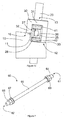
- a first spherical washer 63 is provided to cooperate with first nut 64 and a second spherical washer 67 is provided to cooperate with second nut 66.
- Spherical washers are especially suited for applications in wind turbines in which the rotor shaft has a certain inclination (tilt angle). In alternative embodiments (with no or a small tilt angle), no washers, or plane washers may be used.
- the lifting tool 60 which may be used in embodiments of the present invention are especially suited for lifting a gearbox torque arm of a wind turbine, e.g. a wind turbine such as shown in figure 1 .
- FIGS 3a - 3e schematically illustrate a method for lifting a gearbox torque arm in accordance with an embodiment of the present invention.
- Removable support structure 30 may be disconnected from frame 10.
- the removable support structure may be lifted using e.g. a service crane having a chain hoist, or other hoisting means typically provided in a wind turbine nacelle.
- the hoisting means typically be provided in a nacelle would be capable of lifting a weight of several hundreds of kilograms, and would therefore generally be suitable to lift the removable support structure. It should furthermore be noted that the same hoisting means would typically not be able to lift a gearbox (with a weight of several tons).
- damping element 41 may be removed from between the gearbox torque arm and said structure.
- the removable support structure may once again be fixed to frame 10.
- FIG 3c the step of installing lifting tool 60 with respect to removable support structure 30 and bracket 26 of torque arm 25 is illustrated.
- the rod at a first end 61 extends above the support structure and at its second end 62 extends through bracket 26.
- Nuts and washers are provided at either end. Spherical washers may be used in this case to adjust for the tilt angle.
- Figure 3d illustrates the actual lifting of the gearbox torque arm using lifting tool 60.
- a lifting of the torque arm of the gearbox may be established.
- damping element 42 may be removed, inspected and possibly be substituted.
- gearbox as a whole may be inclined in a transverse direction.
- the turning of the nut(s) of the lifting tool may be carried out using e.g. suitable electric or hydraulic equipment.
- the gearbox torque arm may be lowered in a controlled manner.
- the lifting tool 60 may be removed, and the removable support structure may be lifted for the placement of damping element 41.
- the removable support structure may be attached to the frame again and lifting tool and stabilizing tool may be removed and the maintenance of the damping element that normally is difficult to access will have been completed in relatively cheap and reliable manner.
- a damping element supporting the torque arm on the other side of the gearbox may subsequently be inspected or substituted following the same procedure.
- the stabilizing tool may not be necessary. Since the gearbox is generally connected to the rotor hub through the rotor shaft, the gearbox will generally not shift or tumble, even if the stabilizing tool is not used. Additionally, with smaller tilt angles, there will be no tendency for the gearbox to either move or tumble. Also in these cases, the stabilizing tool may not be necessary.
- any kind of gearbox damping element (or other suitable gearbox support element) may be used.
- an efficient and reliable way of repairing and substituting these damping elements / supports may be obtained.
- the design of the torque arms of the gearbox and the support structure are not limited to the particular examples illustrated in the figures, but instead may vary widely within the scope of the present invention.
- the torque arms may not comprise hollow brackets at their ends.
Landscapes
- Engineering & Computer Science (AREA)
- General Engineering & Computer Science (AREA)
- Mechanical Engineering (AREA)
- Life Sciences & Earth Sciences (AREA)
- Sustainable Development (AREA)
- Sustainable Energy (AREA)
- Chemical & Material Sciences (AREA)
- Combustion & Propulsion (AREA)
- Wind Motors (AREA)
Claims (12)
- Éolienne comprenant une boîte de vitesses (20) ayant un bras de réaction (25), étant une partie d'extrémité du bras de réaction soutenue dans une structure de soutien (30) et supportée par au moins un élément amortisseur (41, 42), dans laquelle
la structure de soutien (30) entoure essentiellement une partie d'extrémité du bras de réaction (25) et caractérisée en ce que
la structure de soutien et le bras de réaction de la boîte de vitesses comprennent des trous (13, 28) verticalement alignés tels qu'une barre (65) d'un outil de levage (60) peut être insérée au travers desdits trous. - Éolienne selon la revendication 1, dans laquelle la partie d'extrémité du bras de réaction est serrée entre deux éléments amortisseurs (41, 42).
- Éolienne selon la revendication 1 ou 2, dans laquelle la structure de soutien est au moins partiellement formée par un cadre (10) sur lequel la boîte de vitesses (20) est montée.
- Éolienne selon l'une quelconque des revendications 1 - 3, dans laquelle la structure de soutien est au moins partiellement amovible.
- Éolienne selon l'une quelconque des revendications 1 - 4, dans laquelle la partie d'extrémité du bras de réaction de la boîte de vitesses comprend un support essentiellement creux (26), étant les trous du bras de réaction de la boîte de vitesses fournis dans ledit support creux.
- Procédé de levage d'un bras de réaction d'une boîte de vitesses dans une éolienne comprenant une boîte de vitesses (20) ayant un bras de réaction (25), étant une partie d'extrémité du bras de réaction (25) soutenue dans une structure de soutien (30) et étant supportée par au moins un élément amortisseur (41, 42), dans lequel la structure de soutien et le bras de réaction de la boîte de vitesses comprennent des trous alignés (13, 28) de façon qu'une barre (65) d'un outil de levage (60) peut être insérée au travers desdits trous, étant le procédé caractérisé en ce que
une barre (60) est insérée au travers des trous fournis dans la structure de soutien (30) et dans le bras de réaction de la boîte de vitesses (25) de façon qu'une première extrémité (61) de la barre s'étend au-dessus de la structure de soutien (30) et une deuxième extrémité s'étend au-dessous du bras de réaction (25) ;
des premiers (64) et deuxièmes écrous (66) sont montés respectivement sur la première et la deuxième extrémité de la barre ;
au moins un des écrous (64, 66) est tourné afin de réduire la séparation entre eux et de lever ainsi le bras de réaction de la boîte de vitesses. - Procédé selon la revendication 6, dans lequel le premier écrou (64) est tourné afin de lever le bras de réaction de la boîte de vitesses.
- Procédé selon l'une quelconque des revendications 6 ou 7, dans lequel au moins un des écrous est tourné en utilisant un outil hydraulique.
- Procédé selon l'une quelconque des revendications 6 - 8, comprenant en outre enlever un élément amortisseur (42) disposé au-dessous d'une partie d'extrémité du bras de réaction de la boîte de vitesses.
- Procédé selon l'une quelconque des revendications 6 - 9, comprenant en outre enlever un élément amortisseur (41) disposé au-dessus du bras de réaction de la boîte de vitesses avant d'insérer une barre au travers des trous.
- Procédé selon la revendication 10, dans lequel l'action d'enlever un élément amortisseur (41) disposé au-dessus du bras de réaction de la boîte de vitesses comprend démonter au moins partiellement la structure de soutien (30) entourant le bras de réaction
enlever un élément amortisseur (41) fourni au-dessus du bras de réaction de la boîte de vitesses, et
assembler de nouveau la structure de soutien (30) entourant le bras de réaction sans l'élément amortisseur. - Procédé selon l'une quelconque des revendications 6 - 11, comprenant en outre établir une connexion entre le bras de réaction (25) et la structure de soutien (30) dans une direction essentiellement horizontale, avant de tourner au moins un des écrous (64, 66) de façon à réduire la séparation entre eux.
Priority Applications (2)
| Application Number | Priority Date | Filing Date | Title |
|---|---|---|---|
| EP11382054.2A EP2495433B1 (fr) | 2011-03-02 | 2011-03-02 | Éolienne et procédé pour lever un bras de couple de boîte de vitesses |
| PCT/EP2012/053576 WO2012117078A1 (fr) | 2011-03-02 | 2012-03-01 | Turbine éolienne, outil de levage et procédé pour lever une jambe de force de boîte de vitesses |
Applications Claiming Priority (1)
| Application Number | Priority Date | Filing Date | Title |
|---|---|---|---|
| EP11382054.2A EP2495433B1 (fr) | 2011-03-02 | 2011-03-02 | Éolienne et procédé pour lever un bras de couple de boîte de vitesses |
Publications (2)
| Publication Number | Publication Date |
|---|---|
| EP2495433A1 EP2495433A1 (fr) | 2012-09-05 |
| EP2495433B1 true EP2495433B1 (fr) | 2016-03-02 |
Family
ID=44262958
Family Applications (1)
| Application Number | Title | Priority Date | Filing Date |
|---|---|---|---|
| EP11382054.2A Active EP2495433B1 (fr) | 2011-03-02 | 2011-03-02 | Éolienne et procédé pour lever un bras de couple de boîte de vitesses |
Country Status (2)
| Country | Link |
|---|---|
| EP (1) | EP2495433B1 (fr) |
| WO (1) | WO2012117078A1 (fr) |
Families Citing this family (5)
| Publication number | Priority date | Publication date | Assignee | Title |
|---|---|---|---|---|
| DK177934B9 (en) * | 2013-06-19 | 2015-01-19 | Envision Energy Denmark Aps | Assembly method for a main rotor shaft and an installation tool thereto |
| JP6494164B2 (ja) | 2014-02-12 | 2019-04-03 | 住友重機械工業株式会社 | トルクアーム構造 |
| JP6517049B2 (ja) * | 2015-03-03 | 2019-05-22 | 住友重機械工業株式会社 | トルクアーム構造 |
| DK178869B1 (en) * | 2015-09-16 | 2017-04-10 | Envision Energy Denmark Aps | Wind turbine with a gear unit and an installation method and an upgrading method thereof |
| ES2613851B1 (es) * | 2015-11-26 | 2018-03-15 | Gamesa Innovation & Technology, S.L. | Dispositivo de absorción de par para cajas multiplicadoras de aerogeneradores |
Family Cites Families (10)
| Publication number | Priority date | Publication date | Assignee | Title |
|---|---|---|---|---|
| GB2018942B (en) * | 1978-03-20 | 1982-06-03 | Aerospatiale | Multi-directional suspension means |
| DE19918379A1 (de) * | 1999-04-22 | 2000-10-26 | Franz Mitsch | Spannbuchse und ihre Verwendung in Windkraftanlagen |
| ATE305101T1 (de) | 2000-10-14 | 2005-10-15 | Franz Mitsch | Getriebelagerung für windkraftanlagen |
| JP4125149B2 (ja) * | 2003-02-04 | 2008-07-30 | 株式会社 神崎高級工機製作所 | 風力発電装置 |
| ES2331801T3 (es) | 2004-02-18 | 2010-01-15 | Franz Mitsch | Rodamiento de elastomero de rigidez regulable. |
| DE202005001519U1 (de) * | 2005-02-01 | 2005-04-07 | Mitsch Franz | Höhenverstellbares Generatorlager |
| CN101363419A (zh) * | 2008-09-17 | 2009-02-11 | 株洲时代新材料科技股份有限公司 | 风力发电机组齿轮箱减振支撑方法及装置 |
| ES2746975T3 (es) | 2008-10-03 | 2020-03-09 | Ge Renewable Tech Wind Bv | Procedimiento y sistema para alinear un componente de un aerogenerador |
| US8596700B2 (en) * | 2009-08-14 | 2013-12-03 | Mjt Holdings, Llc | Tower erection lift kit tools |
| CN201666225U (zh) * | 2009-12-30 | 2010-12-08 | 洛阳双瑞橡塑科技有限公司 | 一种风力发电机齿轮箱用阻尼复合型变刚度减振支撑 |
-
2011
- 2011-03-02 EP EP11382054.2A patent/EP2495433B1/fr active Active
-
2012
- 2012-03-01 WO PCT/EP2012/053576 patent/WO2012117078A1/fr active Application Filing
Also Published As
| Publication number | Publication date |
|---|---|
| WO2012117078A1 (fr) | 2012-09-07 |
| EP2495433A1 (fr) | 2012-09-05 |
Similar Documents
| Publication | Publication Date | Title |
|---|---|---|
| US10352297B2 (en) | Wind power installation and method for adjusting the rotor rotation axis | |
| EP2982862B1 (fr) | Procédé et dispositif de remplacement d'une pale dans des éoliennes | |
| EP2495433B1 (fr) | Éolienne et procédé pour lever un bras de couple de boîte de vitesses | |
| EP3394426B1 (fr) | Procédés pour monter ou démonter des éléments d'éolienne d'une éolienne à rotors multiples | |
| EP2672106A2 (fr) | Système et procédé permettant d'assembler et de désassembler des composants d'une turbine éolienne | |
| CN105270986A (zh) | 风力涡轮机叶片起吊设备及用于起吊风力涡轮机叶片的方法 | |
| EP3263888B1 (fr) | Procédé de manipulation d'une unité de palier à pas de pale de rotor d'éolienne | |
| CN108138752B (zh) | 具有齿轮单元的风力涡轮机及其安装方法和升级方法 | |
| AU2012224580B2 (en) | Wind turbine rotor and method of mounting | |
| US20190136626A1 (en) | External ladder assembly for wind turbine nacelle | |
| US9803739B2 (en) | Gearbox adjustment system | |
| US9028215B2 (en) | Nacelle main frame structure and drive train assembly for a wind turbine | |
| CN106801660B (zh) | 用于安装风力发电机的叶片的方法及设备 | |
| EP3431756B1 (fr) | Procédé de remplacement d'un cadre de générateur d'une éolienne | |
| JP7063977B1 (ja) | ブレードの取り外し方法、ブレードの取り付け方法及び吊治具 | |
| US20220195989A1 (en) | Blade lifting assembly for mounting a blade to or unmounting a blade from a rotor hub of a wind turbine | |
| EP3615794B1 (fr) | Appareil et procédé pour retirer ou installer une unité de palier dans un châssis de nacelle d'éolienne avec un support de palier réglable | |
| GB2534851A (en) | Turbine support structure |
Legal Events
| Date | Code | Title | Description |
|---|---|---|---|
| PUAI | Public reference made under article 153(3) epc to a published international application that has entered the european phase |
Free format text: ORIGINAL CODE: 0009012 |
|
| AK | Designated contracting states |
Kind code of ref document: A1 Designated state(s): AL AT BE BG CH CY CZ DE DK EE ES FI FR GB GR HR HU IE IS IT LI LT LU LV MC MK MT NL NO PL PT RO RS SE SI SK SM TR |
|
| AX | Request for extension of the european patent |
Extension state: BA ME |
|
| 17P | Request for examination filed |
Effective date: 20130305 |
|
| GRAP | Despatch of communication of intention to grant a patent |
Free format text: ORIGINAL CODE: EPIDOSNIGR1 |
|
| RIC1 | Information provided on ipc code assigned before grant |
Ipc: F03D 11/00 20060101ALI20150717BHEP Ipc: F16H 57/025 20120101ALI20150717BHEP Ipc: F03D 1/00 20060101AFI20150717BHEP |
|
| INTG | Intention to grant announced |
Effective date: 20150805 |
|
| GRAS | Grant fee paid |
Free format text: ORIGINAL CODE: EPIDOSNIGR3 |
|
| RAP1 | Party data changed (applicant data changed or rights of an application transferred) |
Owner name: ALSTOM RENEWABLE TECHNOLOGIES |
|
| GRAA | (expected) grant |
Free format text: ORIGINAL CODE: 0009210 |
|
| RIC1 | Information provided on ipc code assigned before grant |
Ipc: F03D 1/00 20060101AFI20160119BHEP Ipc: F16H 57/025 20120101ALI20160119BHEP Ipc: F03D 80/70 20160101ALI20160119BHEP |
|
| AK | Designated contracting states |
Kind code of ref document: B1 Designated state(s): AL AT BE BG CH CY CZ DE DK EE ES FI FR GB GR HR HU IE IS IT LI LT LU LV MC MK MT NL NO PL PT RO RS SE SI SK SM TR |
|
| REG | Reference to a national code |
Ref country code: GB Ref legal event code: FG4D |
|
| REG | Reference to a national code |
Ref country code: AT Ref legal event code: REF Ref document number: 778238 Country of ref document: AT Kind code of ref document: T Effective date: 20160315 Ref country code: CH Ref legal event code: EP |
|
| REG | Reference to a national code |
Ref country code: IE Ref legal event code: FG4D |
|
| REG | Reference to a national code |
Ref country code: FR Ref legal event code: PLFP Year of fee payment: 6 |
|
| REG | Reference to a national code |
Ref country code: DE Ref legal event code: R096 Ref document number: 602011023600 Country of ref document: DE |
|
| REG | Reference to a national code |
Ref country code: NL Ref legal event code: MP Effective date: 20160302 |
|
| REG | Reference to a national code |
Ref country code: LT Ref legal event code: MG4D |
|
| REG | Reference to a national code |
Ref country code: AT Ref legal event code: MK05 Ref document number: 778238 Country of ref document: AT Kind code of ref document: T Effective date: 20160302 |
|
| PG25 | Lapsed in a contracting state [announced via postgrant information from national office to epo] |
Ref country code: NO Free format text: LAPSE BECAUSE OF FAILURE TO SUBMIT A TRANSLATION OF THE DESCRIPTION OR TO PAY THE FEE WITHIN THE PRESCRIBED TIME-LIMIT Effective date: 20160602 Ref country code: FI Free format text: LAPSE BECAUSE OF FAILURE TO SUBMIT A TRANSLATION OF THE DESCRIPTION OR TO PAY THE FEE WITHIN THE PRESCRIBED TIME-LIMIT Effective date: 20160302 Ref country code: HR Free format text: LAPSE BECAUSE OF FAILURE TO SUBMIT A TRANSLATION OF THE DESCRIPTION OR TO PAY THE FEE WITHIN THE PRESCRIBED TIME-LIMIT Effective date: 20160302 Ref country code: ES Free format text: LAPSE BECAUSE OF FAILURE TO SUBMIT A TRANSLATION OF THE DESCRIPTION OR TO PAY THE FEE WITHIN THE PRESCRIBED TIME-LIMIT Effective date: 20160302 Ref country code: GR Free format text: LAPSE BECAUSE OF FAILURE TO SUBMIT A TRANSLATION OF THE DESCRIPTION OR TO PAY THE FEE WITHIN THE PRESCRIBED TIME-LIMIT Effective date: 20160603 |
|
| PG25 | Lapsed in a contracting state [announced via postgrant information from national office to epo] |
Ref country code: AT Free format text: LAPSE BECAUSE OF FAILURE TO SUBMIT A TRANSLATION OF THE DESCRIPTION OR TO PAY THE FEE WITHIN THE PRESCRIBED TIME-LIMIT Effective date: 20160302 Ref country code: PL Free format text: LAPSE BECAUSE OF FAILURE TO SUBMIT A TRANSLATION OF THE DESCRIPTION OR TO PAY THE FEE WITHIN THE PRESCRIBED TIME-LIMIT Effective date: 20160302 Ref country code: SE Free format text: LAPSE BECAUSE OF FAILURE TO SUBMIT A TRANSLATION OF THE DESCRIPTION OR TO PAY THE FEE WITHIN THE PRESCRIBED TIME-LIMIT Effective date: 20160302 Ref country code: NL Free format text: LAPSE BECAUSE OF FAILURE TO SUBMIT A TRANSLATION OF THE DESCRIPTION OR TO PAY THE FEE WITHIN THE PRESCRIBED TIME-LIMIT Effective date: 20160302 Ref country code: LT Free format text: LAPSE BECAUSE OF FAILURE TO SUBMIT A TRANSLATION OF THE DESCRIPTION OR TO PAY THE FEE WITHIN THE PRESCRIBED TIME-LIMIT Effective date: 20160302 Ref country code: RS Free format text: LAPSE BECAUSE OF FAILURE TO SUBMIT A TRANSLATION OF THE DESCRIPTION OR TO PAY THE FEE WITHIN THE PRESCRIBED TIME-LIMIT Effective date: 20160302 Ref country code: LV Free format text: LAPSE BECAUSE OF FAILURE TO SUBMIT A TRANSLATION OF THE DESCRIPTION OR TO PAY THE FEE WITHIN THE PRESCRIBED TIME-LIMIT Effective date: 20160302 Ref country code: BE Free format text: LAPSE BECAUSE OF NON-PAYMENT OF DUE FEES Effective date: 20160331 |
|
| PG25 | Lapsed in a contracting state [announced via postgrant information from national office to epo] |
Ref country code: IS Free format text: LAPSE BECAUSE OF FAILURE TO SUBMIT A TRANSLATION OF THE DESCRIPTION OR TO PAY THE FEE WITHIN THE PRESCRIBED TIME-LIMIT Effective date: 20160702 Ref country code: EE Free format text: LAPSE BECAUSE OF FAILURE TO SUBMIT A TRANSLATION OF THE DESCRIPTION OR TO PAY THE FEE WITHIN THE PRESCRIBED TIME-LIMIT Effective date: 20160302 |
|
| REG | Reference to a national code |
Ref country code: CH Ref legal event code: PL |
|
| PG25 | Lapsed in a contracting state [announced via postgrant information from national office to epo] |
Ref country code: SM Free format text: LAPSE BECAUSE OF FAILURE TO SUBMIT A TRANSLATION OF THE DESCRIPTION OR TO PAY THE FEE WITHIN THE PRESCRIBED TIME-LIMIT Effective date: 20160302 Ref country code: PT Free format text: LAPSE BECAUSE OF FAILURE TO SUBMIT A TRANSLATION OF THE DESCRIPTION OR TO PAY THE FEE WITHIN THE PRESCRIBED TIME-LIMIT Effective date: 20160704 Ref country code: RO Free format text: LAPSE BECAUSE OF FAILURE TO SUBMIT A TRANSLATION OF THE DESCRIPTION OR TO PAY THE FEE WITHIN THE PRESCRIBED TIME-LIMIT Effective date: 20160302 Ref country code: SK Free format text: LAPSE BECAUSE OF FAILURE TO SUBMIT A TRANSLATION OF THE DESCRIPTION OR TO PAY THE FEE WITHIN THE PRESCRIBED TIME-LIMIT Effective date: 20160302 Ref country code: CZ Free format text: LAPSE BECAUSE OF FAILURE TO SUBMIT A TRANSLATION OF THE DESCRIPTION OR TO PAY THE FEE WITHIN THE PRESCRIBED TIME-LIMIT Effective date: 20160302 |
|
| REG | Reference to a national code |
Ref country code: DE Ref legal event code: R097 Ref document number: 602011023600 Country of ref document: DE |
|
| REG | Reference to a national code |
Ref country code: IE Ref legal event code: MM4A |
|
| PG25 | Lapsed in a contracting state [announced via postgrant information from national office to epo] |
Ref country code: IT Free format text: LAPSE BECAUSE OF FAILURE TO SUBMIT A TRANSLATION OF THE DESCRIPTION OR TO PAY THE FEE WITHIN THE PRESCRIBED TIME-LIMIT Effective date: 20160302 Ref country code: BE Free format text: LAPSE BECAUSE OF FAILURE TO SUBMIT A TRANSLATION OF THE DESCRIPTION OR TO PAY THE FEE WITHIN THE PRESCRIBED TIME-LIMIT Effective date: 20160302 |
|
| PLBE | No opposition filed within time limit |
Free format text: ORIGINAL CODE: 0009261 |
|
| STAA | Information on the status of an ep patent application or granted ep patent |
Free format text: STATUS: NO OPPOSITION FILED WITHIN TIME LIMIT |
|
| PG25 | Lapsed in a contracting state [announced via postgrant information from national office to epo] |
Ref country code: LI Free format text: LAPSE BECAUSE OF NON-PAYMENT OF DUE FEES Effective date: 20160331 Ref country code: CH Free format text: LAPSE BECAUSE OF NON-PAYMENT OF DUE FEES Effective date: 20160331 Ref country code: IE Free format text: LAPSE BECAUSE OF NON-PAYMENT OF DUE FEES Effective date: 20160302 Ref country code: DK Free format text: LAPSE BECAUSE OF FAILURE TO SUBMIT A TRANSLATION OF THE DESCRIPTION OR TO PAY THE FEE WITHIN THE PRESCRIBED TIME-LIMIT Effective date: 20160302 |
|
| 26N | No opposition filed |
Effective date: 20161205 |
|
| PG25 | Lapsed in a contracting state [announced via postgrant information from national office to epo] |
Ref country code: BG Free format text: LAPSE BECAUSE OF FAILURE TO SUBMIT A TRANSLATION OF THE DESCRIPTION OR TO PAY THE FEE WITHIN THE PRESCRIBED TIME-LIMIT Effective date: 20160602 Ref country code: SI Free format text: LAPSE BECAUSE OF FAILURE TO SUBMIT A TRANSLATION OF THE DESCRIPTION OR TO PAY THE FEE WITHIN THE PRESCRIBED TIME-LIMIT Effective date: 20160302 |
|
| REG | Reference to a national code |
Ref country code: FR Ref legal event code: PLFP Year of fee payment: 7 |
|
| PG25 | Lapsed in a contracting state [announced via postgrant information from national office to epo] |
Ref country code: MT Free format text: LAPSE BECAUSE OF FAILURE TO SUBMIT A TRANSLATION OF THE DESCRIPTION OR TO PAY THE FEE WITHIN THE PRESCRIBED TIME-LIMIT Effective date: 20160302 |
|
| PG25 | Lapsed in a contracting state [announced via postgrant information from national office to epo] |
Ref country code: MC Free format text: LAPSE BECAUSE OF FAILURE TO SUBMIT A TRANSLATION OF THE DESCRIPTION OR TO PAY THE FEE WITHIN THE PRESCRIBED TIME-LIMIT Effective date: 20160302 |
|
| REG | Reference to a national code |
Ref country code: DE Ref legal event code: R081 Ref document number: 602011023600 Country of ref document: DE Owner name: GE RENEWABLE TECHNOLOGIES WIND B.V., NL Free format text: FORMER OWNER: ALSTOM RENEWABLE TECHNOLOGIES, GRENOBLE, FR |
|
| REG | Reference to a national code |
Ref country code: FR Ref legal event code: CD Owner name: GE RENEWABLE TECHNOLOGIES WIND B.V., NL Effective date: 20180219 Ref country code: FR Ref legal event code: TP Owner name: GE RENEWABLE TECHNOLOGIES WIND B.V., NL Effective date: 20180219 |
|
| REG | Reference to a national code |
Ref country code: FR Ref legal event code: PLFP Year of fee payment: 8 |
|
| REG | Reference to a national code |
Ref country code: GB Ref legal event code: 732E Free format text: REGISTERED BETWEEN 20180315 AND 20180326 |
|
| PG25 | Lapsed in a contracting state [announced via postgrant information from national office to epo] |
Ref country code: CY Free format text: LAPSE BECAUSE OF FAILURE TO SUBMIT A TRANSLATION OF THE DESCRIPTION OR TO PAY THE FEE WITHIN THE PRESCRIBED TIME-LIMIT Effective date: 20160302 Ref country code: HU Free format text: LAPSE BECAUSE OF FAILURE TO SUBMIT A TRANSLATION OF THE DESCRIPTION OR TO PAY THE FEE WITHIN THE PRESCRIBED TIME-LIMIT; INVALID AB INITIO Effective date: 20110302 |
|
| PG25 | Lapsed in a contracting state [announced via postgrant information from national office to epo] |
Ref country code: LU Free format text: LAPSE BECAUSE OF NON-PAYMENT OF DUE FEES Effective date: 20160302 Ref country code: MT Free format text: LAPSE BECAUSE OF FAILURE TO SUBMIT A TRANSLATION OF THE DESCRIPTION OR TO PAY THE FEE WITHIN THE PRESCRIBED TIME-LIMIT Effective date: 20160331 Ref country code: TR Free format text: LAPSE BECAUSE OF FAILURE TO SUBMIT A TRANSLATION OF THE DESCRIPTION OR TO PAY THE FEE WITHIN THE PRESCRIBED TIME-LIMIT Effective date: 20160302 Ref country code: MK Free format text: LAPSE BECAUSE OF FAILURE TO SUBMIT A TRANSLATION OF THE DESCRIPTION OR TO PAY THE FEE WITHIN THE PRESCRIBED TIME-LIMIT Effective date: 20160302 |
|
| PG25 | Lapsed in a contracting state [announced via postgrant information from national office to epo] |
Ref country code: AL Free format text: LAPSE BECAUSE OF FAILURE TO SUBMIT A TRANSLATION OF THE DESCRIPTION OR TO PAY THE FEE WITHIN THE PRESCRIBED TIME-LIMIT Effective date: 20160302 |
|
| P01 | Opt-out of the competence of the unified patent court (upc) registered |
Effective date: 20230530 |
|
| PGFP | Annual fee paid to national office [announced via postgrant information from national office to epo] |
Ref country code: DE Payment date: 20240220 Year of fee payment: 14 Ref country code: GB Payment date: 20240220 Year of fee payment: 14 |
|
| PGFP | Annual fee paid to national office [announced via postgrant information from national office to epo] |
Ref country code: FR Payment date: 20240221 Year of fee payment: 14 |