EP2495433A1 - Windturbine, Hebewerkzeug und Verfahren zum Anheben eines Getriebedrehmomentarms - Google Patents
Windturbine, Hebewerkzeug und Verfahren zum Anheben eines Getriebedrehmomentarms Download PDFInfo
- Publication number
- EP2495433A1 EP2495433A1 EP11382054A EP11382054A EP2495433A1 EP 2495433 A1 EP2495433 A1 EP 2495433A1 EP 11382054 A EP11382054 A EP 11382054A EP 11382054 A EP11382054 A EP 11382054A EP 2495433 A1 EP2495433 A1 EP 2495433A1
- Authority
- EP
- European Patent Office
- Prior art keywords
- torque arm
- gearbox
- support structure
- wind turbine
- rod
- Prior art date
- Legal status (The legal status is an assumption and is not a legal conclusion. Google has not performed a legal analysis and makes no representation as to the accuracy of the status listed.)
- Granted
Links
- 238000000034 method Methods 0.000 title claims abstract description 21
- 238000013016 damping Methods 0.000 claims abstract description 28
- 230000000087 stabilizing effect Effects 0.000 description 7
- 230000005540 biological transmission Effects 0.000 description 2
- 230000013011 mating Effects 0.000 description 2
- 238000006073 displacement reaction Methods 0.000 description 1
- 230000005611 electricity Effects 0.000 description 1
- 238000012423 maintenance Methods 0.000 description 1
- 238000012986 modification Methods 0.000 description 1
- 230000004048 modification Effects 0.000 description 1
Images


Classifications
-
- F—MECHANICAL ENGINEERING; LIGHTING; HEATING; WEAPONS; BLASTING
- F16—ENGINEERING ELEMENTS AND UNITS; GENERAL MEASURES FOR PRODUCING AND MAINTAINING EFFECTIVE FUNCTIONING OF MACHINES OR INSTALLATIONS; THERMAL INSULATION IN GENERAL
- F16H—GEARING
- F16H57/00—General details of gearing
- F16H57/02—Gearboxes; Mounting gearing therein
- F16H57/025—Support of gearboxes, e.g. torque arms, or attachment to other devices
-
- F—MECHANICAL ENGINEERING; LIGHTING; HEATING; WEAPONS; BLASTING
- F03—MACHINES OR ENGINES FOR LIQUIDS; WIND, SPRING, OR WEIGHT MOTORS; PRODUCING MECHANICAL POWER OR A REACTIVE PROPULSIVE THRUST, NOT OTHERWISE PROVIDED FOR
- F03D—WIND MOTORS
- F03D80/00—Details, components or accessories not provided for in groups F03D1/00 - F03D17/00
- F03D80/50—Maintenance or repair
-
- F—MECHANICAL ENGINEERING; LIGHTING; HEATING; WEAPONS; BLASTING
- F03—MACHINES OR ENGINES FOR LIQUIDS; WIND, SPRING, OR WEIGHT MOTORS; PRODUCING MECHANICAL POWER OR A REACTIVE PROPULSIVE THRUST, NOT OTHERWISE PROVIDED FOR
- F03D—WIND MOTORS
- F03D80/00—Details, components or accessories not provided for in groups F03D1/00 - F03D17/00
- F03D80/70—Bearing or lubricating arrangements
-
- F—MECHANICAL ENGINEERING; LIGHTING; HEATING; WEAPONS; BLASTING
- F05—INDEXING SCHEMES RELATING TO ENGINES OR PUMPS IN VARIOUS SUBCLASSES OF CLASSES F01-F04
- F05B—INDEXING SCHEME RELATING TO WIND, SPRING, WEIGHT, INERTIA OR LIKE MOTORS, TO MACHINES OR ENGINES FOR LIQUIDS COVERED BY SUBCLASSES F03B, F03D AND F03G
- F05B2230/00—Manufacture
- F05B2230/60—Assembly methods
- F05B2230/61—Assembly methods using auxiliary equipment for lifting or holding
-
- F—MECHANICAL ENGINEERING; LIGHTING; HEATING; WEAPONS; BLASTING
- F05—INDEXING SCHEMES RELATING TO ENGINES OR PUMPS IN VARIOUS SUBCLASSES OF CLASSES F01-F04
- F05B—INDEXING SCHEME RELATING TO WIND, SPRING, WEIGHT, INERTIA OR LIKE MOTORS, TO MACHINES OR ENGINES FOR LIQUIDS COVERED BY SUBCLASSES F03B, F03D AND F03G
- F05B2230/00—Manufacture
- F05B2230/70—Disassembly methods
-
- F—MECHANICAL ENGINEERING; LIGHTING; HEATING; WEAPONS; BLASTING
- F05—INDEXING SCHEMES RELATING TO ENGINES OR PUMPS IN VARIOUS SUBCLASSES OF CLASSES F01-F04
- F05B—INDEXING SCHEME RELATING TO WIND, SPRING, WEIGHT, INERTIA OR LIKE MOTORS, TO MACHINES OR ENGINES FOR LIQUIDS COVERED BY SUBCLASSES F03B, F03D AND F03G
- F05B2230/00—Manufacture
- F05B2230/80—Repairing, retrofitting or upgrading methods
-
- F—MECHANICAL ENGINEERING; LIGHTING; HEATING; WEAPONS; BLASTING
- F05—INDEXING SCHEMES RELATING TO ENGINES OR PUMPS IN VARIOUS SUBCLASSES OF CLASSES F01-F04
- F05B—INDEXING SCHEME RELATING TO WIND, SPRING, WEIGHT, INERTIA OR LIKE MOTORS, TO MACHINES OR ENGINES FOR LIQUIDS COVERED BY SUBCLASSES F03B, F03D AND F03G
- F05B2240/00—Components
- F05B2240/50—Bearings
-
- F—MECHANICAL ENGINEERING; LIGHTING; HEATING; WEAPONS; BLASTING
- F05—INDEXING SCHEMES RELATING TO ENGINES OR PUMPS IN VARIOUS SUBCLASSES OF CLASSES F01-F04
- F05B—INDEXING SCHEME RELATING TO WIND, SPRING, WEIGHT, INERTIA OR LIKE MOTORS, TO MACHINES OR ENGINES FOR LIQUIDS COVERED BY SUBCLASSES F03B, F03D AND F03G
- F05B2260/00—Function
- F05B2260/96—Preventing, counteracting or reducing vibration or noise
- F05B2260/964—Preventing, counteracting or reducing vibration or noise by damping means
-
- Y—GENERAL TAGGING OF NEW TECHNOLOGICAL DEVELOPMENTS; GENERAL TAGGING OF CROSS-SECTIONAL TECHNOLOGIES SPANNING OVER SEVERAL SECTIONS OF THE IPC; TECHNICAL SUBJECTS COVERED BY FORMER USPC CROSS-REFERENCE ART COLLECTIONS [XRACs] AND DIGESTS
- Y02—TECHNOLOGIES OR APPLICATIONS FOR MITIGATION OR ADAPTATION AGAINST CLIMATE CHANGE
- Y02E—REDUCTION OF GREENHOUSE GAS [GHG] EMISSIONS, RELATED TO ENERGY GENERATION, TRANSMISSION OR DISTRIBUTION
- Y02E10/00—Energy generation through renewable energy sources
- Y02E10/70—Wind energy
- Y02E10/72—Wind turbines with rotation axis in wind direction
-
- Y—GENERAL TAGGING OF NEW TECHNOLOGICAL DEVELOPMENTS; GENERAL TAGGING OF CROSS-SECTIONAL TECHNOLOGIES SPANNING OVER SEVERAL SECTIONS OF THE IPC; TECHNICAL SUBJECTS COVERED BY FORMER USPC CROSS-REFERENCE ART COLLECTIONS [XRACs] AND DIGESTS
- Y02—TECHNOLOGIES OR APPLICATIONS FOR MITIGATION OR ADAPTATION AGAINST CLIMATE CHANGE
- Y02P—CLIMATE CHANGE MITIGATION TECHNOLOGIES IN THE PRODUCTION OR PROCESSING OF GOODS
- Y02P70/00—Climate change mitigation technologies in the production process for final industrial or consumer products
- Y02P70/50—Manufacturing or production processes characterised by the final manufactured product
Definitions
- the present invention relates to a wind turbine, and more particularly relates to a wind turbine comprising a gearbox having a torque arm.
- the present invention also relates to a method for lifting a gearbox torque arm and a lifting tool suitable for use in such a method.
- Wind turbines are commonly used to supply electricity into the electrical grid.
- Wind turbines of this kind generally comprise a rotor with a rotor hub and a plurality of blades.
- the rotor is set into rotation under the influence of the wind on the blades.
- the rotation of the rotor shaft either directly drives the generator rotor ("directly driven") or through the use of a gearbox.
- EP 1 197 677 discloses a wind turbine comprising a gearbox having wedge-shaped flanges. The flanges are supported by damping elements.
- EP 1 566 543 discloses adjustable damping elements supporting the torque arms of a wind turbine gearbox.
- EP 2 172 647 discloses a wind turbine with a gearbox.
- the torque arms of the gearbox are supported by flexible supports.
- the invention provides a wind turbine comprising a gearbox having a torque arm, an end portion of the torque arm being held in a support structure and being supported by at least one damping element, wherein the support structure and the gearbox torque arm comprise aligned through-holes such that a rod of a lifting tool can be fitted through said through-holes.
- a wind turbine is provided which is adapted to be lifted using a lifting tool comprising a rod, which generally may be less complicated and less expensive than in prior art systems and methods.
- the invention provides a lifting tool for lifting a gearbox torque arm in such a wind turbine comprising a longitudinal rod having a first end and a second end, wherein portions of the rod near the first and second ends comprise threads, the lifting tool further comprising a first nut adapted to cooperate with the threads at the first end and a second nut adapted to cooperate with the threads at the second end, the rod adapted to be fitted through the holes provided in the torque arm and the support structure, and having a length such that when fitted through the holes, it extends beyond said holes on both sides.
- a lifting tool is provided which may be used for lifting a gearbox torque arm sufficiently such that a damping element provided underneath the torque arm may be inspected, repaired and/or replaced.
- it is not necessary to lift or remove the complete gearbox.
- the support structure already surrounding the torque arm is used. There is thus no need for e.g. an additional crane.
- the invention provides a method for lifting a gearbox torque arm in such a wind turbine comprising inserting a rod through the through-holes provided in the support structure and gearbox torque arm such that a first end of the rod extends above the support structure and a second end extends underneath the torque arm; mounting first and second nuts at the first and second end of the rod respectively; turning at least one of the nuts such as to reduce the distance between them and thereby raise the gearbox torque arm.
- the end portion of the torque arm is clamped between two damping elements.
- the damping element on top of the torque arm may first be removed before lifting the torque arm.
- the support structure may need to be at least partially disassembled.
- the rod of the lifting tool comprises threads substantially along its entire length. In alternative embodiments, only portions of the rod are provided with threads.
- the lifting tool comprises at least one washer.
- one or more spherical washers may be used. Spherical washers may be used to compensate for small misalignments between parts.
- a connection between the torque arm and the support structure in a substantially horizontal direction is provided. In these embodiments, it can be assured that no horizontal displacement occurs during lifting of the gearbox even when the rotor shaft has a substantial tilting angle.
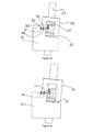
- Figure 1a illustrates a side view of a wind turbine gearbox 20 which is mounted on a frame 10.
- Frame 10 may form part of a nacelle which may be rotatably mounted on a wind turbine tower. Both gearbox 20 and the top surface of frame 10 may be slightly inclined due to a tilt angle of the rotor shaft.
- a flange 21 for connecting to the low speed shaft (i.e. the rotor shaft) and the high speed shaft 29 which in use drives the generator.
- the gearbox 20 furthermore comprises a mounting flange 23, from which torque arms 25 extend on either side of the gearbox.
- the torque arms in this embodiment each comprise a hollow rectangular bracket 26 at an end portion.
- Damping elements 41 and 42 are provided respectively on top of and underneath the bracket 26.
- a gearbox support structure is provided, which in this embodiment is formed by fixed frame 10 and removable support structure 30.
- the gearbox support structure may thus substantially surround an end portion of the torque arms.
- Figure 1c illustrates a side view of the same wind turbine comprising a frame 10 upon which a gearbox is mounted.
- the gearbox has been represented merely by the mounting flange for reasons of clarity.
- the removable support structure in this embodiment is substantially U-shaped having a base 31 and two legs 32, 33 extending from its base.
- the ends of the legs 32, 33 of the removable support structure may be fixed to the frame, as schematically indicated with reference signs 11 and 12.
- Torque arm 25 and damping elements 41, 42 may thus adequately be clamped in the support structure and the damping elements may at least partially reduce the transmissions of vibrations from the gearbox to the frame 10 and tower.
- Both support structure 30 and torque arm 25 comprise aligned holes, such that a rod may be inserted through them.
- the base 31 of the U-shaped removable support structure 30 and bracket 26 may have aligned holes suitable for fitting a rod. This has been schematically indicated in figure 2a with reference signs 13 and 28 respectively.
- a stabilizing tool that avoids tumbling or horizontal shifting of the gearbox when it is being lifted may be provided.
- Such a tool may be fastened using suitable holes 16 provided in frame 10 and holes 27 provided in torque arm 25. This will be further explained with reference to figures 3a - 3e .
- FIG. 2 illustrates a lifting tool in accordance with an embodiment of the present invention
- the lifting tool 60 comprises a rod 65 having a first end 61 and a second end 62. Threaded portions are provided at or near either end of the rod, such that a first nut 64 with mating threads may be mounted at the first end 61 of the rod and such that a second nut 66 with mating threads may be mounted at the second end 62 of the rod.
- a first spherical washer 63 is provided to cooperate with first nut 64 and a second spherical washer 67 is provided to cooperate with second nut 66.
- Spherical washers are especially suited for applications in wind turbines in which the rotor shaft has a certain inclination (tilt angle). In alternative embodiments (with no or a small tilt angle), no washers, or plane washers may be used.
- Embodiments of the lifting tool 60 according to the present invention are especially suited for lifting a gearbox torque arm of a wind turbine, e.g. a wind turbine such as shown in figure 1 .
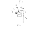
- FIGS 3a - 3e schematically illustrate a method for lifting a gearbox torque arm in accordance with an embodiment of the present invention.
- stabilizing tool 50 that aids to avoid tumbling or horizontal shifting of the gearbox when it is being lifted is mounted.
- stabilizing tool 50 comprises a rod 53 with a first mounting bracket 51 at a first end to fix it to frame 10 and a second mounting bracket 52 to fix it to torque arm 25.
- Mounting brackets 51 and 52 are connected to the rod 53 through hinges, such that a relative movement between mounting brackets and rod is possible.
- Removable support structure 30 may be disconnected from frame 10.
- the removable support structure may be lifted using e.g. a service crane having a chain hoist, or other hoisting means typically provided in a wind turbine nacelle.
- the hoisting means typically be provided in a nacelle would be capable of lifting a weight of several hundreds of kilograms, and would therefore generally be suitable to lift the removable support structure. It should furthermore be noted that the same hoisting means would typically not be able to lift a gearbox (with a weight of several tons).
- damping element 41 may be removed from between the gearbox torque arm and said structure.
- the removable support structure may once again be fixed to frame 10.
- FIG 3c the step of installing lifting tool 60 with respect to removable support structure 30 and bracket 26 of torque arm 25 is illustrated.
- the rod at a first end 61 extends above the support structure and at its second end 62 extends through bracket 26.
- Nuts and washers are provided at either end. Spherical washers may be used in this case to adjust for the tilt angle.
- Figure 3d illustrates the actual lifting of the gearbox torque arm using lifting tool 60.
- a lifting of the torque arm of the gearbox may be established.
- damping element 42 may be removed, inspected and possibly be substituted.
- gearbox as a whole may be inclined in a transverse direction.
- the turning of the nut(s) of the lifting tool may be carried out using e.g. suitable electric or hydraulic equipment.
- the gearbox torque arm may be lowered in a controlled manner.
- the lifting tool 60 may be removed, and the removable support structure may be lifted for the placement of damping element 41.
- the removable support structure may be attached to the frame again and lifting tool and stabilizing tool may be removed and the maintenance of the damping element that normally is difficult to access will have been completed in relatively cheap and reliable manner.
- a damping element supporting the torque arm on the other side of the gearbox may subsequently be inspected or substituted following the same procedure.
- the stabilizing tool may not be necessary. Since the gearbox is generally connected to the rotor hub through the rotor shaft, the gearbox will generally not shift or tumble, even if the stabilizing tool is not used. Additionally, with smaller tilt angles, there will be no tendency for the gearbox to either move or tumble. Also in these cases, the stabilizing tool may not be necessary.
- any kind of gearbox damping element (or other suitable gearbox support element) may be used.
- an efficient and reliable way of repairing and substituting these damping elements / supports may be obtained.
- the design of the torque arms of the gearbox and the support structure are not limited to the particular examples illustrated in the figures, but instead may vary widely within the scope of the present invention.
- the torque arms may not comprise hollow brackets at their ends.
Priority Applications (2)
| Application Number | Priority Date | Filing Date | Title |
|---|---|---|---|
| EP11382054.2A EP2495433B1 (de) | 2011-03-02 | 2011-03-02 | Windturbine und Verfahren zum Anheben eines Getriebedrehmomentarms |
| PCT/EP2012/053576 WO2012117078A1 (en) | 2011-03-02 | 2012-03-01 | Wind turbine, lifting tool and method for lifting a gearbox torque arm |
Applications Claiming Priority (1)
| Application Number | Priority Date | Filing Date | Title |
|---|---|---|---|
| EP11382054.2A EP2495433B1 (de) | 2011-03-02 | 2011-03-02 | Windturbine und Verfahren zum Anheben eines Getriebedrehmomentarms |
Publications (2)
| Publication Number | Publication Date |
|---|---|
| EP2495433A1 true EP2495433A1 (de) | 2012-09-05 |
| EP2495433B1 EP2495433B1 (de) | 2016-03-02 |
Family
ID=44262958
Family Applications (1)
| Application Number | Title | Priority Date | Filing Date |
|---|---|---|---|
| EP11382054.2A Active EP2495433B1 (de) | 2011-03-02 | 2011-03-02 | Windturbine und Verfahren zum Anheben eines Getriebedrehmomentarms |
Country Status (2)
| Country | Link |
|---|---|
| EP (1) | EP2495433B1 (de) |
| WO (1) | WO2012117078A1 (de) |
Cited By (5)
| Publication number | Priority date | Publication date | Assignee | Title |
|---|---|---|---|---|
| EP2816224A1 (de) * | 2013-06-19 | 2014-12-24 | Envision Energy (Denmark) ApS | Montageverfahren für eine Hauptrotorwelle und Installationswerkzeug dafür |
| JP2015152035A (ja) * | 2014-02-12 | 2015-08-24 | 住友重機械工業株式会社 | トルクアーム構造 |
| JP2016161061A (ja) * | 2015-03-03 | 2016-09-05 | 住友重機械工業株式会社 | トルクアーム構造 |
| WO2017045688A1 (en) * | 2015-09-16 | 2017-03-23 | Envision Energy (Denmark) Aps | Wind turbine with a gear unit and an installation method and an upgrading method thereof |
| ES2613851A1 (es) * | 2015-11-26 | 2017-05-26 | Gamesa Innovation & Technology, S.L. | Dispositivo de absorción de par para cajas multiplicadoras de aerogeneradores |
Citations (10)
| Publication number | Priority date | Publication date | Assignee | Title |
|---|---|---|---|---|
| GB2018942A (en) * | 1978-03-20 | 1979-10-24 | Aerospatiale | Multi-directional suspension means |
| EP1046832A1 (de) * | 1999-04-22 | 2000-10-25 | Franz Mitsch | Spannbuchse und ihre Verwendung in Windkraftanlagen |
| EP1197677A2 (de) | 2000-10-14 | 2002-04-17 | Franz Mitsch | Getriebelagerung für Windkraftanlagen |
| JP2004239113A (ja) * | 2003-02-04 | 2004-08-26 | Kanzaki Kokyukoki Mfg Co Ltd | 風力発電装置 |
| DE202005001519U1 (de) * | 2005-02-01 | 2005-04-07 | Mitsch Franz | Höhenverstellbares Generatorlager |
| EP1566543A1 (de) | 2004-02-18 | 2005-08-24 | Franz Mitsch | Elastomerlagerung mit regulierbarer Steifigkeit |
| CN101363419A (zh) * | 2008-09-17 | 2009-02-11 | 株洲时代新材料科技股份有限公司 | 风力发电机组齿轮箱减振支撑方法及装置 |
| EP2172647A1 (de) | 2008-10-03 | 2010-04-07 | Ecotecnia Energias Renovables, S.L. | Verfahren und System zum Ausrichten einer Windturbinenkomponente |
| CN201666225U (zh) * | 2009-12-30 | 2010-12-08 | 洛阳双瑞橡塑科技有限公司 | 一种风力发电机齿轮箱用阻尼复合型变刚度减振支撑 |
| WO2011020086A2 (en) * | 2009-08-14 | 2011-02-17 | Mjt Holdings, Llc | Tower erection lift kit tools |
-
2011
- 2011-03-02 EP EP11382054.2A patent/EP2495433B1/de active Active
-
2012
- 2012-03-01 WO PCT/EP2012/053576 patent/WO2012117078A1/en active Application Filing
Patent Citations (10)
| Publication number | Priority date | Publication date | Assignee | Title |
|---|---|---|---|---|
| GB2018942A (en) * | 1978-03-20 | 1979-10-24 | Aerospatiale | Multi-directional suspension means |
| EP1046832A1 (de) * | 1999-04-22 | 2000-10-25 | Franz Mitsch | Spannbuchse und ihre Verwendung in Windkraftanlagen |
| EP1197677A2 (de) | 2000-10-14 | 2002-04-17 | Franz Mitsch | Getriebelagerung für Windkraftanlagen |
| JP2004239113A (ja) * | 2003-02-04 | 2004-08-26 | Kanzaki Kokyukoki Mfg Co Ltd | 風力発電装置 |
| EP1566543A1 (de) | 2004-02-18 | 2005-08-24 | Franz Mitsch | Elastomerlagerung mit regulierbarer Steifigkeit |
| DE202005001519U1 (de) * | 2005-02-01 | 2005-04-07 | Mitsch Franz | Höhenverstellbares Generatorlager |
| CN101363419A (zh) * | 2008-09-17 | 2009-02-11 | 株洲时代新材料科技股份有限公司 | 风力发电机组齿轮箱减振支撑方法及装置 |
| EP2172647A1 (de) | 2008-10-03 | 2010-04-07 | Ecotecnia Energias Renovables, S.L. | Verfahren und System zum Ausrichten einer Windturbinenkomponente |
| WO2011020086A2 (en) * | 2009-08-14 | 2011-02-17 | Mjt Holdings, Llc | Tower erection lift kit tools |
| CN201666225U (zh) * | 2009-12-30 | 2010-12-08 | 洛阳双瑞橡塑科技有限公司 | 一种风力发电机齿轮箱用阻尼复合型变刚度减振支撑 |
Cited By (12)
| Publication number | Priority date | Publication date | Assignee | Title |
|---|---|---|---|---|
| EP2816224A1 (de) * | 2013-06-19 | 2014-12-24 | Envision Energy (Denmark) ApS | Montageverfahren für eine Hauptrotorwelle und Installationswerkzeug dafür |
| DK201370334A1 (en) * | 2013-06-19 | 2015-01-12 | Envision Energy Denmark Aps | Assembly method for a main rotor shaft and an installation tool thereto |
| US9624902B2 (en) | 2013-06-19 | 2017-04-18 | Envision Energy (Denmark) Aps | Assembly method for a main rotor shaft and an installation tool thereto |
| JP2015152035A (ja) * | 2014-02-12 | 2015-08-24 | 住友重機械工業株式会社 | トルクアーム構造 |
| US9897191B2 (en) | 2014-02-12 | 2018-02-20 | Sumitomo Heavy Industries, Ltd. | Torque arm structure |
| JP2016161061A (ja) * | 2015-03-03 | 2016-09-05 | 住友重機械工業株式会社 | トルクアーム構造 |
| WO2017045688A1 (en) * | 2015-09-16 | 2017-03-23 | Envision Energy (Denmark) Aps | Wind turbine with a gear unit and an installation method and an upgrading method thereof |
| DK178869B1 (en) * | 2015-09-16 | 2017-04-10 | Envision Energy Denmark Aps | Wind turbine with a gear unit and an installation method and an upgrading method thereof |
| CN108138752A (zh) * | 2015-09-16 | 2018-06-08 | 远景能源(江苏)有限公司 | 具有齿轮单元的风力涡轮机及其安装方法和升级方法 |
| CN108138752B (zh) * | 2015-09-16 | 2019-12-27 | 远景能源(江苏)有限公司 | 具有齿轮单元的风力涡轮机及其安装方法和升级方法 |
| ES2613851A1 (es) * | 2015-11-26 | 2017-05-26 | Gamesa Innovation & Technology, S.L. | Dispositivo de absorción de par para cajas multiplicadoras de aerogeneradores |
| EP3173620A1 (de) * | 2015-11-26 | 2017-05-31 | Gamesa Innovation & Technology, S.L. | Drehmomentaufnehmer für windturbinengetriebe |
Also Published As
| Publication number | Publication date |
|---|---|
| WO2012117078A1 (en) | 2012-09-07 |
| EP2495433B1 (de) | 2016-03-02 |
Similar Documents
| Publication | Publication Date | Title |
|---|---|---|
| US10352297B2 (en) | Wind power installation and method for adjusting the rotor rotation axis | |
| EP2982862B1 (de) | Verfahren und vorrichtung zum austauschen von schaufeln bei windturbinen | |
| EP2495433B1 (de) | Windturbine und Verfahren zum Anheben eines Getriebedrehmomentarms | |
| EP2672106A2 (de) | System und Verfahren zur Montage und Demontage von Bauteilen einer Windkraftturbine | |
| EP3394426B1 (de) | Verfahren zur montage oder demontage von windturbinenkomponenten einer mehrrotor-windturbine | |
| EP2461021A2 (de) | Windkraftgenerator und Gierlagerwechselverfahren für einen Windkraftgenerator | |
| EP3431751B1 (de) | System und verfahren zur uptower-aufhängung einer rotorschaufel einer windturbine | |
| EP3263888B1 (de) | Verfahren zur handhabung einer windturbinenrotorblattanstelllagereinheit | |
| US20140072430A1 (en) | Wind turbine rotor and method of mounting | |
| CN108138752B (zh) | 具有齿轮单元的风力涡轮机及其安装方法和升级方法 | |
| US9803739B2 (en) | Gearbox adjustment system | |
| US9028215B2 (en) | Nacelle main frame structure and drive train assembly for a wind turbine | |
| CN115467796A (zh) | 支撑组件 | |
| EP3431756B1 (de) | Verfahren zum auswechseln eines generatorrahmens einer windturbine | |
| US20220195989A1 (en) | Blade lifting assembly for mounting a blade to or unmounting a blade from a rotor hub of a wind turbine | |
| CN219412790U (zh) | 一种基于多个滑轮组的风力发电机叶片更换设备 | |
| CN219587708U (zh) | 一种基于螺纹固定的风力发电机叶片更换装置 | |
| US10436180B2 (en) | Apparatus and method for removing or installing a bearing unit in a wind turbine bedplate with an adjustable bearing support | |
| JP2022100013A (ja) | ブレードの取り外し方法、ブレードの取り付け方法及び吊治具 | |
| KR20230099794A (ko) | 가스 터빈 디스크 인양 지그 | |
| CN117279858A (zh) | 用于支撑便携式起重机的基座和用于移除风力涡轮机的主轴承的方法 |
Legal Events
| Date | Code | Title | Description |
|---|---|---|---|
| PUAI | Public reference made under article 153(3) epc to a published international application that has entered the european phase |
Free format text: ORIGINAL CODE: 0009012 |
|
| AK | Designated contracting states |
Kind code of ref document: A1 Designated state(s): AL AT BE BG CH CY CZ DE DK EE ES FI FR GB GR HR HU IE IS IT LI LT LU LV MC MK MT NL NO PL PT RO RS SE SI SK SM TR |
|
| AX | Request for extension of the european patent |
Extension state: BA ME |
|
| 17P | Request for examination filed |
Effective date: 20130305 |
|
| GRAP | Despatch of communication of intention to grant a patent |
Free format text: ORIGINAL CODE: EPIDOSNIGR1 |
|
| RIC1 | Information provided on ipc code assigned before grant |
Ipc: F03D 11/00 20060101ALI20150717BHEP Ipc: F16H 57/025 20120101ALI20150717BHEP Ipc: F03D 1/00 20060101AFI20150717BHEP |
|
| INTG | Intention to grant announced |
Effective date: 20150805 |
|
| GRAS | Grant fee paid |
Free format text: ORIGINAL CODE: EPIDOSNIGR3 |
|
| RAP1 | Party data changed (applicant data changed or rights of an application transferred) |
Owner name: ALSTOM RENEWABLE TECHNOLOGIES |
|
| GRAA | (expected) grant |
Free format text: ORIGINAL CODE: 0009210 |
|
| RIC1 | Information provided on ipc code assigned before grant |
Ipc: F03D 1/00 20060101AFI20160119BHEP Ipc: F16H 57/025 20120101ALI20160119BHEP Ipc: F03D 80/70 20160101ALI20160119BHEP |
|
| AK | Designated contracting states |
Kind code of ref document: B1 Designated state(s): AL AT BE BG CH CY CZ DE DK EE ES FI FR GB GR HR HU IE IS IT LI LT LU LV MC MK MT NL NO PL PT RO RS SE SI SK SM TR |
|
| REG | Reference to a national code |
Ref country code: GB Ref legal event code: FG4D |
|
| REG | Reference to a national code |
Ref country code: AT Ref legal event code: REF Ref document number: 778238 Country of ref document: AT Kind code of ref document: T Effective date: 20160315 Ref country code: CH Ref legal event code: EP |
|
| REG | Reference to a national code |
Ref country code: IE Ref legal event code: FG4D |
|
| REG | Reference to a national code |
Ref country code: FR Ref legal event code: PLFP Year of fee payment: 6 |
|
| REG | Reference to a national code |
Ref country code: DE Ref legal event code: R096 Ref document number: 602011023600 Country of ref document: DE |
|
| REG | Reference to a national code |
Ref country code: NL Ref legal event code: MP Effective date: 20160302 |
|
| REG | Reference to a national code |
Ref country code: LT Ref legal event code: MG4D |
|
| REG | Reference to a national code |
Ref country code: AT Ref legal event code: MK05 Ref document number: 778238 Country of ref document: AT Kind code of ref document: T Effective date: 20160302 |
|
| PG25 | Lapsed in a contracting state [announced via postgrant information from national office to epo] |
Ref country code: NO Free format text: LAPSE BECAUSE OF FAILURE TO SUBMIT A TRANSLATION OF THE DESCRIPTION OR TO PAY THE FEE WITHIN THE PRESCRIBED TIME-LIMIT Effective date: 20160602 Ref country code: FI Free format text: LAPSE BECAUSE OF FAILURE TO SUBMIT A TRANSLATION OF THE DESCRIPTION OR TO PAY THE FEE WITHIN THE PRESCRIBED TIME-LIMIT Effective date: 20160302 Ref country code: HR Free format text: LAPSE BECAUSE OF FAILURE TO SUBMIT A TRANSLATION OF THE DESCRIPTION OR TO PAY THE FEE WITHIN THE PRESCRIBED TIME-LIMIT Effective date: 20160302 Ref country code: ES Free format text: LAPSE BECAUSE OF FAILURE TO SUBMIT A TRANSLATION OF THE DESCRIPTION OR TO PAY THE FEE WITHIN THE PRESCRIBED TIME-LIMIT Effective date: 20160302 Ref country code: GR Free format text: LAPSE BECAUSE OF FAILURE TO SUBMIT A TRANSLATION OF THE DESCRIPTION OR TO PAY THE FEE WITHIN THE PRESCRIBED TIME-LIMIT Effective date: 20160603 |
|
| PG25 | Lapsed in a contracting state [announced via postgrant information from national office to epo] |
Ref country code: AT Free format text: LAPSE BECAUSE OF FAILURE TO SUBMIT A TRANSLATION OF THE DESCRIPTION OR TO PAY THE FEE WITHIN THE PRESCRIBED TIME-LIMIT Effective date: 20160302 Ref country code: PL Free format text: LAPSE BECAUSE OF FAILURE TO SUBMIT A TRANSLATION OF THE DESCRIPTION OR TO PAY THE FEE WITHIN THE PRESCRIBED TIME-LIMIT Effective date: 20160302 Ref country code: SE Free format text: LAPSE BECAUSE OF FAILURE TO SUBMIT A TRANSLATION OF THE DESCRIPTION OR TO PAY THE FEE WITHIN THE PRESCRIBED TIME-LIMIT Effective date: 20160302 Ref country code: NL Free format text: LAPSE BECAUSE OF FAILURE TO SUBMIT A TRANSLATION OF THE DESCRIPTION OR TO PAY THE FEE WITHIN THE PRESCRIBED TIME-LIMIT Effective date: 20160302 Ref country code: LT Free format text: LAPSE BECAUSE OF FAILURE TO SUBMIT A TRANSLATION OF THE DESCRIPTION OR TO PAY THE FEE WITHIN THE PRESCRIBED TIME-LIMIT Effective date: 20160302 Ref country code: RS Free format text: LAPSE BECAUSE OF FAILURE TO SUBMIT A TRANSLATION OF THE DESCRIPTION OR TO PAY THE FEE WITHIN THE PRESCRIBED TIME-LIMIT Effective date: 20160302 Ref country code: LV Free format text: LAPSE BECAUSE OF FAILURE TO SUBMIT A TRANSLATION OF THE DESCRIPTION OR TO PAY THE FEE WITHIN THE PRESCRIBED TIME-LIMIT Effective date: 20160302 Ref country code: BE Free format text: LAPSE BECAUSE OF NON-PAYMENT OF DUE FEES Effective date: 20160331 |
|
| PG25 | Lapsed in a contracting state [announced via postgrant information from national office to epo] |
Ref country code: IS Free format text: LAPSE BECAUSE OF FAILURE TO SUBMIT A TRANSLATION OF THE DESCRIPTION OR TO PAY THE FEE WITHIN THE PRESCRIBED TIME-LIMIT Effective date: 20160702 Ref country code: EE Free format text: LAPSE BECAUSE OF FAILURE TO SUBMIT A TRANSLATION OF THE DESCRIPTION OR TO PAY THE FEE WITHIN THE PRESCRIBED TIME-LIMIT Effective date: 20160302 |
|
| REG | Reference to a national code |
Ref country code: CH Ref legal event code: PL |
|
| PG25 | Lapsed in a contracting state [announced via postgrant information from national office to epo] |
Ref country code: SM Free format text: LAPSE BECAUSE OF FAILURE TO SUBMIT A TRANSLATION OF THE DESCRIPTION OR TO PAY THE FEE WITHIN THE PRESCRIBED TIME-LIMIT Effective date: 20160302 Ref country code: PT Free format text: LAPSE BECAUSE OF FAILURE TO SUBMIT A TRANSLATION OF THE DESCRIPTION OR TO PAY THE FEE WITHIN THE PRESCRIBED TIME-LIMIT Effective date: 20160704 Ref country code: RO Free format text: LAPSE BECAUSE OF FAILURE TO SUBMIT A TRANSLATION OF THE DESCRIPTION OR TO PAY THE FEE WITHIN THE PRESCRIBED TIME-LIMIT Effective date: 20160302 Ref country code: SK Free format text: LAPSE BECAUSE OF FAILURE TO SUBMIT A TRANSLATION OF THE DESCRIPTION OR TO PAY THE FEE WITHIN THE PRESCRIBED TIME-LIMIT Effective date: 20160302 Ref country code: CZ Free format text: LAPSE BECAUSE OF FAILURE TO SUBMIT A TRANSLATION OF THE DESCRIPTION OR TO PAY THE FEE WITHIN THE PRESCRIBED TIME-LIMIT Effective date: 20160302 |
|
| REG | Reference to a national code |
Ref country code: DE Ref legal event code: R097 Ref document number: 602011023600 Country of ref document: DE |
|
| REG | Reference to a national code |
Ref country code: IE Ref legal event code: MM4A |
|
| PG25 | Lapsed in a contracting state [announced via postgrant information from national office to epo] |
Ref country code: IT Free format text: LAPSE BECAUSE OF FAILURE TO SUBMIT A TRANSLATION OF THE DESCRIPTION OR TO PAY THE FEE WITHIN THE PRESCRIBED TIME-LIMIT Effective date: 20160302 Ref country code: BE Free format text: LAPSE BECAUSE OF FAILURE TO SUBMIT A TRANSLATION OF THE DESCRIPTION OR TO PAY THE FEE WITHIN THE PRESCRIBED TIME-LIMIT Effective date: 20160302 |
|
| PLBE | No opposition filed within time limit |
Free format text: ORIGINAL CODE: 0009261 |
|
| STAA | Information on the status of an ep patent application or granted ep patent |
Free format text: STATUS: NO OPPOSITION FILED WITHIN TIME LIMIT |
|
| PG25 | Lapsed in a contracting state [announced via postgrant information from national office to epo] |
Ref country code: LI Free format text: LAPSE BECAUSE OF NON-PAYMENT OF DUE FEES Effective date: 20160331 Ref country code: CH Free format text: LAPSE BECAUSE OF NON-PAYMENT OF DUE FEES Effective date: 20160331 Ref country code: IE Free format text: LAPSE BECAUSE OF NON-PAYMENT OF DUE FEES Effective date: 20160302 Ref country code: DK Free format text: LAPSE BECAUSE OF FAILURE TO SUBMIT A TRANSLATION OF THE DESCRIPTION OR TO PAY THE FEE WITHIN THE PRESCRIBED TIME-LIMIT Effective date: 20160302 |
|
| 26N | No opposition filed |
Effective date: 20161205 |
|
| PG25 | Lapsed in a contracting state [announced via postgrant information from national office to epo] |
Ref country code: BG Free format text: LAPSE BECAUSE OF FAILURE TO SUBMIT A TRANSLATION OF THE DESCRIPTION OR TO PAY THE FEE WITHIN THE PRESCRIBED TIME-LIMIT Effective date: 20160602 Ref country code: SI Free format text: LAPSE BECAUSE OF FAILURE TO SUBMIT A TRANSLATION OF THE DESCRIPTION OR TO PAY THE FEE WITHIN THE PRESCRIBED TIME-LIMIT Effective date: 20160302 |
|
| REG | Reference to a national code |
Ref country code: FR Ref legal event code: PLFP Year of fee payment: 7 |
|
| PG25 | Lapsed in a contracting state [announced via postgrant information from national office to epo] |
Ref country code: MT Free format text: LAPSE BECAUSE OF FAILURE TO SUBMIT A TRANSLATION OF THE DESCRIPTION OR TO PAY THE FEE WITHIN THE PRESCRIBED TIME-LIMIT Effective date: 20160302 |
|
| PG25 | Lapsed in a contracting state [announced via postgrant information from national office to epo] |
Ref country code: MC Free format text: LAPSE BECAUSE OF FAILURE TO SUBMIT A TRANSLATION OF THE DESCRIPTION OR TO PAY THE FEE WITHIN THE PRESCRIBED TIME-LIMIT Effective date: 20160302 |
|
| REG | Reference to a national code |
Ref country code: DE Ref legal event code: R081 Ref document number: 602011023600 Country of ref document: DE Owner name: GE RENEWABLE TECHNOLOGIES WIND B.V., NL Free format text: FORMER OWNER: ALSTOM RENEWABLE TECHNOLOGIES, GRENOBLE, FR |
|
| REG | Reference to a national code |
Ref country code: FR Ref legal event code: CD Owner name: GE RENEWABLE TECHNOLOGIES WIND B.V., NL Effective date: 20180219 Ref country code: FR Ref legal event code: TP Owner name: GE RENEWABLE TECHNOLOGIES WIND B.V., NL Effective date: 20180219 |
|
| REG | Reference to a national code |
Ref country code: FR Ref legal event code: PLFP Year of fee payment: 8 |
|
| REG | Reference to a national code |
Ref country code: GB Ref legal event code: 732E Free format text: REGISTERED BETWEEN 20180315 AND 20180326 |
|
| PG25 | Lapsed in a contracting state [announced via postgrant information from national office to epo] |
Ref country code: CY Free format text: LAPSE BECAUSE OF FAILURE TO SUBMIT A TRANSLATION OF THE DESCRIPTION OR TO PAY THE FEE WITHIN THE PRESCRIBED TIME-LIMIT Effective date: 20160302 Ref country code: HU Free format text: LAPSE BECAUSE OF FAILURE TO SUBMIT A TRANSLATION OF THE DESCRIPTION OR TO PAY THE FEE WITHIN THE PRESCRIBED TIME-LIMIT; INVALID AB INITIO Effective date: 20110302 |
|
| PG25 | Lapsed in a contracting state [announced via postgrant information from national office to epo] |
Ref country code: LU Free format text: LAPSE BECAUSE OF NON-PAYMENT OF DUE FEES Effective date: 20160302 Ref country code: MT Free format text: LAPSE BECAUSE OF FAILURE TO SUBMIT A TRANSLATION OF THE DESCRIPTION OR TO PAY THE FEE WITHIN THE PRESCRIBED TIME-LIMIT Effective date: 20160331 Ref country code: TR Free format text: LAPSE BECAUSE OF FAILURE TO SUBMIT A TRANSLATION OF THE DESCRIPTION OR TO PAY THE FEE WITHIN THE PRESCRIBED TIME-LIMIT Effective date: 20160302 Ref country code: MK Free format text: LAPSE BECAUSE OF FAILURE TO SUBMIT A TRANSLATION OF THE DESCRIPTION OR TO PAY THE FEE WITHIN THE PRESCRIBED TIME-LIMIT Effective date: 20160302 |
|
| PG25 | Lapsed in a contracting state [announced via postgrant information from national office to epo] |
Ref country code: AL Free format text: LAPSE BECAUSE OF FAILURE TO SUBMIT A TRANSLATION OF THE DESCRIPTION OR TO PAY THE FEE WITHIN THE PRESCRIBED TIME-LIMIT Effective date: 20160302 |
|
| PGFP | Annual fee paid to national office [announced via postgrant information from national office to epo] |
Ref country code: FR Payment date: 20230222 Year of fee payment: 13 |
|
| P01 | Opt-out of the competence of the unified patent court (upc) registered |
Effective date: 20230530 |
|
| PGFP | Annual fee paid to national office [announced via postgrant information from national office to epo] |
Ref country code: DE Payment date: 20240220 Year of fee payment: 14 Ref country code: GB Payment date: 20240220 Year of fee payment: 14 |