EP2495411A1 - Abgasanlagenkomponente - Google Patents
Abgasanlagenkomponente Download PDFInfo
- Publication number
- EP2495411A1 EP2495411A1 EP12152494A EP12152494A EP2495411A1 EP 2495411 A1 EP2495411 A1 EP 2495411A1 EP 12152494 A EP12152494 A EP 12152494A EP 12152494 A EP12152494 A EP 12152494A EP 2495411 A1 EP2495411 A1 EP 2495411A1
- Authority
- EP
- European Patent Office
- Prior art keywords
- pressure
- housing
- deformation
- housing wall
- component according
- Prior art date
- Legal status (The legal status is an assumption and is not a legal conclusion. Google has not performed a legal analysis and makes no representation as to the accuracy of the status listed.)
- Granted
Links
Images


Classifications
-
- F—MECHANICAL ENGINEERING; LIGHTING; HEATING; WEAPONS; BLASTING
- F01—MACHINES OR ENGINES IN GENERAL; ENGINE PLANTS IN GENERAL; STEAM ENGINES
- F01N—GAS-FLOW SILENCERS OR EXHAUST APPARATUS FOR MACHINES OR ENGINES IN GENERAL; GAS-FLOW SILENCERS OR EXHAUST APPARATUS FOR INTERNAL-COMBUSTION ENGINES
- F01N13/00—Exhaust or silencing apparatus characterised by constructional features
- F01N13/18—Construction facilitating manufacture, assembly, or disassembly
-
- F—MECHANICAL ENGINEERING; LIGHTING; HEATING; WEAPONS; BLASTING
- F01—MACHINES OR ENGINES IN GENERAL; ENGINE PLANTS IN GENERAL; STEAM ENGINES
- F01N—GAS-FLOW SILENCERS OR EXHAUST APPARATUS FOR MACHINES OR ENGINES IN GENERAL; GAS-FLOW SILENCERS OR EXHAUST APPARATUS FOR INTERNAL-COMBUSTION ENGINES
- F01N13/00—Exhaust or silencing apparatus characterised by constructional features
-
- F—MECHANICAL ENGINEERING; LIGHTING; HEATING; WEAPONS; BLASTING
- F01—MACHINES OR ENGINES IN GENERAL; ENGINE PLANTS IN GENERAL; STEAM ENGINES
- F01N—GAS-FLOW SILENCERS OR EXHAUST APPARATUS FOR MACHINES OR ENGINES IN GENERAL; GAS-FLOW SILENCERS OR EXHAUST APPARATUS FOR INTERNAL-COMBUSTION ENGINES
- F01N13/00—Exhaust or silencing apparatus characterised by constructional features
- F01N13/18—Construction facilitating manufacture, assembly, or disassembly
- F01N13/1805—Fixing exhaust manifolds, exhaust pipes or pipe sections to each other, to engine or to vehicle body
- F01N13/1811—Fixing exhaust manifolds, exhaust pipes or pipe sections to each other, to engine or to vehicle body with means permitting relative movement, e.g. compensation of thermal expansion or vibration
Definitions
- the present invention relates to an exhaust system component for an exhaust system of an internal combustion engine, in particular of a motor vehicle.
- Conventional exhaust system components such. Ex. Silencer, particulate filter, catalysts, SCR systems and the like, usually include a housing having at least one housing wall which separates an internal pressure of the exhaust system during operation of the interior of the housing from a surrounding housing surrounding, having an ambient pressure environment.
- the internal pressure is greater than the ambient pressure, so that the respective housing wall is exposed to an outwardly oriented pressure force.
- the housings are to be manufactured with smaller wall thicknesses.
- thinner housing walls may become more deformed due to the aforementioned compressive forces occurring during operation. Such deformations can lead to a noise at the appropriate frequency.
- joints, z. Ex. Welds exposed by such deformations very high mechanical loads. Thus, such induced by the internal pressure deformations affect the life of the respective exhaust system component.
- the present invention is concerned with the problem of providing for an exhaust system component of the type mentioned an improved embodiment, which is particularly characterized in that it is particularly suitable for the realization of a lightweight construction.
- the lifetime should be increased and / or the noise emission should be reduced.
- the invention is based on the general idea to equip the housing with at least one stiffening element, wherein the respective stiffening element is arranged and configured so that it counteracts a deformation of the housing wall exposed to the internal pressure.
- the housing can thus be stiffened in such a way that a deformation tendency of the affected housing wall is reduced.
- the housing wall affected by the deformation itself can be stiffened by the respective stiffening element.
- the respective stiffening element is a separate component with respect to the respective housing wall, which is attached to the housing.
- the respective stiffening element into the respective housing wall, for example by producing the respective housing wall from a so-called tailored blank.
- the respective stiffening element has a significantly smaller area than the housing wall, so that overall the desired weight saving can be realized.
- the stability of the housing can be achieved with the aid of the respective stiffening element, while the gas-tightness of the housing is realized with the aid of the respective housing wall.
- virtually a functional separation can be realized, so that the housing wall is more or less relieved of its supporting function within the housing by the use of the respective stiffening element.
- the respective stiffening element can be designed rod-shaped or web-shaped or wire-shaped or band-shaped.
- Such rectilinear stiffening element can be provided in particular endlessly on coils, windings and the like and is characterized by an extremely high tensile strength in a small space.
- the respective housing wall can be stiffened linear.
- the respective stiffening element to a tension-resistant tension element, such. Eg a wire or a band or a rope.
- the respective tension element may be arranged on an outer side facing the environment of the respective housing wall.
- outwardly oriented forces can be particularly easily converted to the respective tension element in tensile forces, which can be particularly easily absorbed and removed by the respective tension element.
- the respective tension element can be fastened to the housing only in the region of its longitudinal ends, so that the respective tension element absorbs the compressive forces between its ends and is supported on the housing in the form of tensile forces.
- the respective tension element can also be configured so that it is closed in an annular manner, so that the tensile forces can be absorbed completely within the respective tension element.
- the respective tension element in particular between its longitudinal ends, comes to rest loosely in a deformation region of the respective housing wall affected by the pressure-related deformation.
- the housing wall and tension element are possible in order to avoid mechanical tension.
- At least one holder or a holding frame can be arranged outside of a deformation region of the respective housing wall which is affected by the pressure-related deformation on the housing on which the respective tension element is supported.
- the fixation or support of the respective tension element does not take place directly on the housing, but via said holder or holding frame.
- the introduction of force from the respective tension element can be improved on the housing on the specially designed holder or support frame.
- At least one such stiffening element can be configured as a pressure-stable pressure element.
- a pressure element can, for example, be a profile carrier with basically any profile cross section.
- closed profiles or hollow profiles such as. Eg Rectangle profile, circle profile.
- open profiles can be used, such. Eg T-profile, L-profile, H-profile.
- the respective pressure element can now be arranged on an inner side of the respective housing wall facing the inner space.
- the respective pressure element can be mounted so that it is attached only in the region of its longitudinal ends on the housing.
- an annularly closed circumferential configuration is also conceivable for the respective pressure element.
- the respective pressure element preferably between its longitudinal ends, in a deformation region affected by the deformation caused by pressure on the respective housing wall loosely rest or be spaced from the housing wall.
- the mode of action of the respective pressure element thus differs fundamentally from the mode of action of the tension element described above.
- the respective traction element braces the housing wall affected by the deformation, so as to direct the Deformation of the housing wall to counteract
- the respective pressure element leads to a stiffening of the housing and thereby indirectly counteracts a deformation of the respective housing wall. This is based on the consideration that the deformation of the housing wall inevitably goes hand in hand with a deformation of the housing, at least under certain installation conditions. If the housing is then stiffened with the aid of the respective pressure element, the tendency for the deformation of the respective housing wall can be correspondingly reduced.
- the respective pressure element made of a material such. Ex. Austenite, exist whose coefficient of thermal expansion is greater than the coefficient of thermal expansion of the material, such. Eg ferrite, from which the respective housing wall consists.
- the respective exhaust system component heats up.
- the respective pressure element can expand more than the respective housing wall, which leads to a bias that is opposite to the pressure load.
- the positioning of the respective pressure element is deliberately carried out so that the thermal expansion of the pressure element already leads to a stress-induced deformation of the housing or the respective housing wall.
- the respective pressure element is arranged in the interior, so that the pressure element reaches higher temperatures than the respective housing wall, which is exposed on its outside of the relatively cold environment.
- the respective pressure element in the housing can be arranged so that it during operation of the Exhaust system exhaust gas or even an exhaust gas flow is exposed, which increases the thermal expansion of the respective pressure element.
- the respective stiffening element may extend between its longitudinal ends in a groove which is integrally formed on or in the respective housing wall, for example by means of a bead.
- a positioning transversely to the longitudinal axis of the respective stiffening element is achieved in particular for elongated stiffening elements.
- the respective housing wall is already preformed in a deformation region affected by the pressure-related deformation in the direction of the deformation or in the opposite direction.
- the respective stiffening element is fastened to the housing only in the region of its longitudinal ends, in each case in a fastening region which is not affected by the pressure-related deformation or is less affected than a deformation region affected by the pressure-related deformation whose deformation counteracts the respective stiffening element.
- Such an embodiment is particularly suitable for housing with an oval or elliptical, at least not circular cross-section. Deformation areas are then those peripheral portions with larger bending radii, while attachment areas are then peripheral portions with smaller bending radii.
- At least one stiffening element is designed as a tension-resistant tension element which is assigned to a housing region which seeks to be removed during the pressure load from a diametrically opposite housing region.
- At least one stiffening element is designed as a pressure-stable pressure element, which supports two diametrically opposite housing areas to each other, which seek to approach in the pressure load. This also allows an intensive stiffening of the housing can be realized to reduce pressure-induced deformations.
- an exhaust system component 1 comprises a housing 2 and at least one stiffening element 3.
- the exhaust system component 1, which may also be referred to below as component 1, is intended for use in an exhaust system of an internal combustion engine, preferably a motor vehicle, preferably a commercial vehicle.
- the component 1 is, for example, a muffler or an exhaust gas treatment device, such.
- a particulate filter or a catalyst or a NOX storage or a 3-way catalytic converter or an SCR system In principle, it can also be a combination of the above institutions.
- the housing 2 has at least one housing wall 4, which separates an interior 5 of the housing 2 from an environment 6 of the housing 2.
- an internal pressure Pi In the operation of the exhaust system prevails in the interior 5 an internal pressure Pi, while in the environment 6 an ambient pressure Pu prevails, usually the internal pressure Pi is greater than the ambient pressure Pu.
- the housing wall 4 is indicated by an arrow pressure load. 7 exposed.
- This pressure load 7 induces a deformation of the housing wall 4. Usually, this results in a curvature of the housing wall 4 to the outside, ie in the direction of environment 6.
- This deformation now counteracts the respective stiffening element 3.
- the respective stiffening element 3 is attached and arranged in a suitable manner on the housing 2.
- Fig. 1 to 11 is the respective stiffening element 3 rod-shaped or web-shaped.
- the show Fig. 1 to 9 a wire-shaped configuration of the stiffening element 3.
- a wire-shaped stiffening element 3 has a circular cross-section.
- a band-shaped stiffening element 3 has a rectangular cross-section.
- the stiffening elements 3 are conceivable as single or multiple curved shapes.
- At least the embodiments of the Fig. 1 to 6 show at least one stiffening element 3, which is designed as a tension-resistant tension element 8.
- Tensile elements 8 are, for example, a wire or a band or a rope.
- the respective tension element 8 is arranged on one of the surroundings 6 facing outside of the respective housing wall 4. As a result, the respective tension element 3 can counteract the outwardly oriented deformation of the housing wall 4 in a particularly effective manner.
- the examples of the tension elements 8 shown here are designed such that the respective tension element 8 is fastened to the housing 2 exclusively in the region of its longitudinal ends. Corresponding attachment points are designated 9. Between the longitudinal ends of the tension element 8 can rest against the respective housing wall 4 loosely, at least in one of the As a result, the assembly of the tension elements 8 on the housing 2 is simplified.
- corresponding holders 11 or a holding frame 12 can be provided on the housing 2.
- the respective holder 11 or the respective holding frame 12 is arranged on one of the surroundings 6 facing outside of the housing 2, that is attached to the housing 2, z. Ex.
- welds 13 according to Fig. 2 And is positioned outside of the deforming region 10 of the housing wall 4 affected by the pressure-related deformation.
- the respective tension element 8 can now be fixed or supported.
- Fig. 2 shows a special type of fixation 9, which allows a rotation of the tension member 8 about a rotation axis 14, which coincides with the longitudinal axis of the tension member 8 in the region of the fixation 9.
- the rotation is realized purely by way of example with a spherical end element 15 of the tension element 8.
- Fig. 1 to 5 show exemplarily, as with the help of the tension elements 8 designed as an end bottom housing wall 4 can be supported from the outside to reduce the pressure-induced deformations.
- the show Fig. 6 to 11 Embodiments in which a shell-side housing wall 4 can be protected by means of the stiffening elements 3 from a pressure-induced deformation.
- Fig. 6 an embodiment in which the housing 2 is designed comparatively flat and a dimensionally stable housing wall 4 'and a flexible housing wall. 4 wherein the flexible housing wall 4 is stabilized with respect to the pressure-induced deformation with the aid of the at least one stiffening element 3, which is also designed here as a tension element 8.
- Fig. 7 to 9 show a housing 2 with elliptical cross-section.
- housing portions 16 are diametrically opposed with a larger bending radius and offset by 90 ° to housing areas are also diametrically opposite with smaller bending radii.
- the housing regions 16 with a larger bending radius try to move away from each other, while the housing regions 17 with a smaller bending radius try to approach each other.
- this pressure-induced deformation is in the in Fig.
- At least one stiffening element 3 is provided, which is designed as a tension element 8 and which fixes the two housing portions 16 with a larger bending radius to each other and thus prevents it from each other at a pressure load.
- Arrows 18 indicate the generated with the help of the respective tension element 8 opposing forces, which counteract the pressure-induced deformation.
- At the in Fig. 8 in the embodiment shown, at least one stiffening element 3 is designed as a pressure-stable pressure element 19 and arranged such that it supports the two housing regions 17 with smaller bending radii. This prevents that these two housing portions 17 in the case of a pressure load of the housing 2 approach each other.
- the opposing forces generated by means of the pressure element 19 are in Fig. 8 indicated by arrows 20 and counteract the pressure-induced deformation of these housing portions 17.
- the 10 and 11 show a further embodiment in which at least one stiffening element 3 is designed as a pressure-resistant pressure element 19.
- the pressure element 19 is preferably a profile carrier. Shown in the 10 and 11 In this case, a profile carrier with an L-profile as a pressure element 19.
- T-profiles or H-profiles or closed hollow sections such as circular profiles or rectangular profiles are conceivable.
- the respective pressure element 19 is arranged on an inner side of the respective housing wall 4 facing the inner space 5.
- the respective pressure element 19 is attached to the housing 2 exclusively in the region of its longitudinal ends.
- the corresponding fastening points are again denoted by 9 and can be formed, for example, by welding points.
- an annularly closed circumferential configuration for the pressure elements 19 is also conceivable here.
- the respective pressure element 19 is positioned such that it is spaced apart from the housing wall 4 in the deformation region 10 affected by the pressure-related deformation, which in the case of the elliptical housing 2 shown here coincides with the housing regions 16 with a larger bending radius. Likewise, it is basically possible for the respective pressure element 19 to rest loosely against the housing wall 4 in said deformation area 10.
- Fig. 10 shown configuration with the printing elements 19 corresponds largely to in Fig. 8 shown configuration.
- the respective pressure element 19 consists of a material whose temperature expansion coefficient is greater than the coefficient of thermal expansion of the material of which the respective housing wall 4 consists.
- the respective pressure element 19 may be made of austenite material, while the respective housing wall 4 is made of ferrite material.
- pressure element 19 and housing wall 4 heat up.
- the pressure element 19 expands more than the housing wall 4, whereby the opposing forces 20 of the pressure element 19, which counteract the deformation of the housing wall 4 due to the compressive forces 7, are increased. This effect is assisted by the fact that the housing wall 4 is exposed to the environment 6, so that the housing wall 4 is usually colder than the pressure elements 19 arranged in the interior 5.
- a variant in which the respective pressure element 19 in the housing is also particularly advantageous 2 is positioned so that it in the operation of the exhaust system exhaust gas or a in Fig. 11 is exposed by arrows indicated exhaust gas flow 21.
- the pressure elements 19 reach higher temperatures than the housing wall. 4
- the respective stiffening element 3 here the pressure elements 19 in the region of the longitudinal ends is fixed in each case in a mounting region 22 of the respective housing wall 4, which is not or less affected by the pressure-induced deformation of the housing wall 4 as the deformation region 10 Case of the elliptical housing 2, these attachment portions 22 correspond to the housing portions 17 with a smaller bending radius.
- the stiffening elements 3 arranged inside or outside, in particular between their longitudinal ends, can run in a groove which is integrally formed on the respective housing wall 4, for example by means of a bead.
- a groove 23 is indicated.
- the respective housing wall 4 may already be preformed in a deformation region 10 affected by the pressure-related deformation in the direction of the deformation or the compressive forces 7. As a result, a part of the deformation is anticipated, which increases the dimensional stability of the housing wall in the deformation region.
- This negative pre-deformation can be realized, for example, with the aid of the stiffening elements 3 and is preferably realized in the region of elastic deformations. In this way, the housing wall 4 is biased against the pressure load. In operation, then the pressure load, which initially, up to a predetermined pressure, leads to a discharge of the housing wall 4, since only the bias of the housing wall 4 is used up. By this measure, a particularly dimensionally stable structure for the housing 2 can be realized.
Landscapes
- Engineering & Computer Science (AREA)
- Chemical & Material Sciences (AREA)
- Combustion & Propulsion (AREA)
- Mechanical Engineering (AREA)
- General Engineering & Computer Science (AREA)
- Exhaust Gas After Treatment (AREA)
- Exhaust Silencers (AREA)
Abstract
Description
- Die vorliegende Erfindung betrifft eine Abgasanlagenkomponente für eine Abgasanlage einer Brennkraftmaschine, insbesondere eines Kraftfahrzeugs.
- Herkömmliche Abgasanlagenkomponenten, wie z. Bsp. Schalldämpfer, Partikelfilter, Katalysatoren, SCR-Systeme und dergleichen, umfassen üblicherweise ein Gehäuse, das zumindest eine Gehäusewand aufweist, die einen im Betrieb der Abgasanlage einem Innendruck ausgesetzten Innenraum des Gehäuses von einer das Gehäuse umgebenden, einen Umgebungsdruck aufweisenden Umgebung trennt. Üblicherweise ist dabei der Innendruck größer als der Umgebungsdruck, so dass die jeweilige Gehäusewand einer nach außen orientierten Druckkraft ausgesetzt ist. Um bei Kraftfahrzeugen den Kraftstoffverbrauch zu reduzieren, wird unter anderem versucht, möglichst viel Gewicht einzusparen. Im Hinblick auf Abgasanlagenkomponenten bedeutet dies, dass die Gehäuse mit kleineren Wandstärken hergestellt werden sollen. Dünnere Gehäusewände können sich jedoch aufgrund der zuvor genannten, im Betrieb auftretenden Druckkräfte stärker verformen. Derartige Verformungen können bei entsprechender Frequenz zu einer Geräuschentwicklung führen. Zum anderen sind insbesondere Verbindungsstellen, z. Bsp. Schweißnähte, durch derartige Verformungen sehr hohen mechanischen Belastungen ausgesetzt. Somit können derartige, durch den Innendruck induzierte Verformungen die Lebensdauer der jeweiligen Abgasanlagenkomponente beeinträchtigen.
- Die vorliegende Erfindung beschäftigt sich mit dem Problem, für eine Abgasanlagenkomponente der eingangs genannten Art eine verbesserte Ausführungsform anzugeben, die sich insbesondere dadurch auszeichnet, dass sie sich in besonderer Weise zur Realisierung einer Leichtbauausführung eignet. Insbesondere sollen die Lebensdauer erhöht und/oder die Geräuschemission reduziert werden.
- Dieses Problem wird erfindungsgemäß durch den Gegenstand des unabhängigen Anspruchs gelöst. Vorteilhafte Ausführungsformen sind Gegenstand der abhängigen Ansprüche.
- Die Erfindung beruht auf dem allgemeinen Gedanken, das Gehäuse mit wenigstens einem Versteifungselement auszustatten, wobei das jeweilige Versteifungselement so angeordnet und ausgestaltet ist, dass es einer Verformung der dem Innendruck ausgesetzten Gehäusewand entgegenwirkt. Mit Hilfe des jeweiligen Versteifungselements kann somit einerseits das Gehäuse derart ausgesteift werden, dass eine Verformungstendenz der betroffenen Gehäusewand reduziert ist. Andererseits kann die von der Verformung betroffene Gehäusewand selbst durch das jeweilige Versteifungselement versteift werden. Zweckmäßig handelt es sich beim jeweiligen Versteifungselement um ein bezüglich der jeweiligen Gehäusewand separates Bauteil, das an das Gehäuse angebaut wird. Alternativ ist es grundsätzlich ebenso möglich, das jeweilige Versteifungselement in die jeweilige Gehäusewand zu integrieren, bspw. durch die Herstellung der jeweiligen Gehäusewand aus einem so genannten Tailored-Blank. Es ist klar, dass das jeweilige Versteifungselement eine deutliche kleinere Fläche besitzt als die Gehäusewand, so dass insgesamt die gewünschte Gewichtseinsparung realisierbar ist. Durch die Verwendung wenigstens eines solchen Versteifungselements kann die Stabilität des Gehäuses mit Hilfe des jeweiligen Versteifungselements erzielt werden, während die Gasdichtigkeit des Gehäuses mit Hilfe der jeweiligen Gehäusewand realisiert wird. Insoweit kann quasi eine funktionale Trennung realisiert werden, so dass die Gehäusewand von ihrer tragenden Funktion innerhalb des Gehäuses durch die Verwendung des jeweiligen Versteifungselements mehr oder weniger entlastet ist.
- Entsprechend einer vorteilhaften Ausführungsform kann das jeweilige Versteifungselement stabförmig oder stegförmig oder drahtförmig oder bandförmig ausgestaltet sein. Derartiges geradliniges Versteifungselement kann insbesondere endlos auf Spulen, Wicklungen und dergleichen bereitgestellt werden und zeichnet sich durch eine extrem hohe Zugfestigkeit bei kleinem Bauraum aus. Somit kann die jeweilige Gehäusewand linienförmig ausgesteift werden. Besonders zweckmäßig handelt es sich beim jeweiligen Versteifungselement um ein zugstabiles Zugelement, wie z. Bsp. um einen Draht oder ein Band oder ein Seil.
- Gemäß einer anderen Ausführungsform kann das jeweilige Zugelement an einer der Umgebung zugewandten Außenseite der jeweiligen Gehäusewand angeordnet sein. Auf diese Weise lassen sich nach außen orientierte Kräfte besonders einfach am jeweiligen Zugelement in Zugkräfte umwandeln, die vom jeweiligen Zugelement besonders einfach aufgenommen und abgetragen werden können. Zweckmäßig kann das jeweilige Zugelement nur im Bereich seiner Längsenden am Gehäuse befestigt sein, so dass das jeweilige Zugelement zwischen seinen Enden die Druckkräfte aufnimmt und in Form von Zugkräften am Gehäuse abstützt. Alternativ dazu kann das jeweilige Zugelement auch ringförmig geschlossen umlaufend ausgestaltet sein, so dass die Zugkräfte vollständig innerhalb des jeweiligen Zugelements aufgenommen werden können. Desweiteren kann vorgesehen sein, dass das jeweilige Zugelement, insbesondere zwischen seinen Längsenden, in einem von der druckbedingten Verformung betroffenen Verformungsbereich der jeweiligen Gehäusewand lose zur Anlage kommt. Hierdurch sind insbesondere Relativbewegungen zwischen Gehäusewand und Zugelement möglich, um mechanische Verspannungen zu vermeiden.
- Gemäß einer anderen vorteilhaften Ausführungsform kann am Gehäuse an einer der Umgebung zugewandten Außenseite zumindest ein Halter oder ein Halterahmen außerhalb eines von der druckbedingten Verformung betroffenen Verformungsbereichs der jeweiligen Gehäusewand angeordnet sein, an dem das jeweilige Zugelement abgestützt ist. Somit erfolgt die Fixierung bzw. Abstützung des jeweiligen Zugelements nicht unmittelbar am Gehäuse, sondern über besagten Halter bzw. Halterahmen. Somit kann die Krafteinleitung vom jeweiligen Zugelement auf das Gehäuse über den speziell dafür gestalteten Halter bzw. Halterahmen verbessert werden.
- Gemäß einer anderen Ausführungsform kann wenigstens ein solches Versteifungselement als druckstabiles Druckelement ausgestaltet sein. Ein derartiges Druckelement kann bspw. ein Profilträger mit grundsätzlich beliebigem Profilquerschnitt sein. Beispielsweise eignen sich geschlossene Profile oder Hohlprofile, wie z. Bsp. Rechteck-Profil, Kreis-Profil. Ferner können auch offene Profile verwendet werden, wie z. Bsp. T-Profil, L-Profil, H-Profil.
- Zweckmäßig kann nun das jeweilige Druckelement an einer dem Innenraum zugewandten Innenseite der jeweiligen Gehäusewand angeordnet sein. Dabei kann das jeweilige Druckelement so angebracht werden, dass es nur im Bereich seiner Längsenden am Gehäuse befestigt ist. Alternativ ist auch für das jeweilige Druckelement eine ringförmig geschlossen umlaufende Konfiguration denkbar. Besonders zweckmäßig kann das jeweilige Druckelement, vorzugsweise zwischen seinen Längsenden, in einem von der druckbedingten Verformung betroffenen Verformungsbereich an der jeweiligen Gehäusewand lose anliegen oder von der Gehäusewand beabstandet sein. Die Wirkungsweise des jeweiligen Druckelements unterscheidet sich somit grundsätzlich von der Wirkungsweise des zuvor beschriebenen Zugelements. Während das jeweilige Zugelement die von der Verformung betroffene Gehäusewand aussteift, um so direkt der Verformung der Gehäusewand entgegen zu wirken, führt das jeweilige Druckelement zu einer Aussteifung des Gehäuses und wirkt dadurch indirekt einer Verformung der jeweiligen Gehäusewand entgegen. Dies beruht auf der Überlegung, dass die Verformung der Gehäusewand zumindest bei bestimmten Montagebedingungen zwangsläufig mit einer Verformung des Gehäuses einhergeht. Wird nun mit Hilfe des jeweiligen Druckelements das Gehäuse versteift, lässt sich die Tendenz zur Verformung der jeweiligen Gehäusewand entsprechend reduzieren.
- Entsprechend einer besonders vorteilhaften Ausführungsform kann das jeweilige Druckelement aus einem Material, wie z. Bsp. Austenit, bestehen, dessen Temperaturausdehnungskoeffizient größer ist als der Temperaturausdehnungskoeffizient des Materials, wie z. Bsp. Ferrit, aus dem die jeweilige Gehäusewand besteht. Im Betrieb der Abgasanlage heizt sich die jeweilige Abgasanlagenkomponente auf. Hierbei kann sich das jeweilige Druckelement stärker ausdehnen als die jeweilige Gehäusewand, was zu einer Vorspannung führt, die der Druckbelastung entgegengesetzt ist. Das bedeutet, dass die Positionierung des jeweiligen Druckelements gezielt so erfolgt, dass bereits die thermische Ausdehnung des Druckelements zu einer der druckinduzierten Verformung entgegen gerichteten Verspannung des Gehäuses bzw. der jeweiligen Gehäusewand führt. Unterstützt wird dieser Effekt dadurch, dass gemäß einer vorteilhaften Ausführungsform das jeweilige Druckelement im Innenraum angeordnet ist, so dass das Druckelement höhere Temperaturen erreicht als die jeweilige Gehäusewand, die an ihrer Außenseite der vergleichsweise kalten Umgebung ausgesetzt ist.
- Gemäß einer besonders vorteilhaften Weiterbildung kann das jeweilige Druckelement im Gehäuse so angeordnet sein, dass es im Betrieb der Abgasanlage Abgas oder sogar einer Abgasströmung ausgesetzt ist, was die thermische Ausdehnung des jeweiligen Druckelements erhöht.
- Gemäß einer anderen Ausführungsform kann das jeweilige Versteifungselement zwischen seinen Längsenden in einer Nut verlaufen, die an bzw. in der jeweiligen Gehäusewand integral ausgebildet ist, bspw. mittels einer Sicke. Hierdurch wird insbesondere für längliche Versteifungselemente eine Positionierung quer zur Längsachse des jeweiligen Versteifungselements erreicht.
- Ferner kann gemäß einer vorteilhaften Ausführungsform vorgesehen sein, dass die jeweilige Gehäusewand in einem von der druckbedingten Verformung betroffenen Verformungsbereich in Richtung der Verformung oder in der Gegenrichtung bereits vorgeformt ist.
- Gemäß einer anderen vorteilhaften Ausführungsform kann vorgesehen sein, dass das jeweilige Versteifungselement nur im Bereich seiner Längsenden am Gehäuse befestigt ist, und zwar jeweils in einem Befestigungsbereich, der von der druckbedingten Verformung nicht betroffen ist oder weniger betroffen ist als ein von der druckbedingten Verformung betroffener Verformungsbereich, dessen Verformung das jeweilige Versteifungselement entgegenwirkt. Eine derartige Ausführungsform eignet sich insbesondere für Gehäuse mit ovalem oder elliptischem, jedenfalls nicht kreisförmigem Querschnitt. Verformungsbereiche sind dann diejenigen Umfangsabschnitte mit größeren Biegeradien, während Befestigungsbereiche dann Umfangsabschnitte mit kleineren Biegeradien sind.
- Bei einer anderen vorteilhaften Ausführungsform kann vorgesehen sein, dass zumindest ein Versteifungselement als zugstabiles Zugelement ausgestaltet ist, das einem Gehäusebereich zugeordnet ist, der sich bei der Druckbelastung von einem diametral gegenüberliegenden Gehäusebereich zu entfernen sucht.
- Zusätzlich oder alternativ ist zumindest ein Versteifungselement als druckstabiles Druckelement ausgestaltet, das zwei einander diametral gegenüberliegende Gehäusebereiche aneinander abstützt, die sich bei der Druckbelastung zu nähern suchen. Auch hierdurch kann eine intensive Aussteifung des Gehäuses realisiert werden, um druckbedingte Verformungen zu reduzieren.
- Weitere wichtige Merkmale und Vorteile der Erfindung ergeben sich aus den Unteransprüchen, aus den Zeichnungen und aus der zugehörigen Figurenbeschreibung anhand der Zeichnungen.
- Es versteht sich, dass die vorstehend genannten und die nachstehend noch zu erläuternden Merkmale nicht nur in der jeweils angegebenen Kombination, sondern auch in anderen Kombinationen oder in Alleinstellung verwendbar sind, ohne den Rahmen der vorliegenden Erfindung zu verlassen.
- Bevorzugte Ausführungsbeispiele der Erfindung sind in den Zeichnungen dargestellt und werden in der nachfolgenden Beschreibung näher erläutert, wobei sich gleiche Bezugszeichen auf gleiche oder ähnliche oder funktional gleiche Bauteile beziehen.
- Es zeigen, jeweils schematisch,
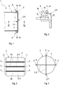
- Fig. 1
- eine stark vereinfachte Schnittansicht einer Abgasanlagenkomponente im Bereich einer Gehäusewand,
- Fig. 2
- ein vergrößertes Detail II aus
Fig. 1 im Bereich einer Halterung, - Fig. 3 bis 5
- Frontansichten auf die Gehäusewand bei verschiedenen Ausführungsformen,
- Fig. 6 bis 9
- Querschnitte der Abgasanlagenkomponente bei verschiedenen Ausführungsformen,
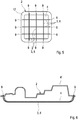
- Fig. 10
- ein Querschnitt der Abgasanlagenkomponente bei einer weiteren Ausführungsform gemäß Schnittlinien X in
Fig. 11 , - Fig. 11
- ein Längsschnitt der weiteren Ausführungsform entsprechend Schnittlinien XI in
Fig. 10 . - Entsprechend den
Fig. 1 bis 11 umfasst eine Abgasanlagenkomponente 1 ein Gehäuse 2 und zumindest ein Versteifungselement 3. Die Abgasanlagenkomponente 1, die im Folgenden auch als Komponente 1 bezeichnet werden kann, ist für die Verwendung in einer Abgasanlage einer Brennkraftmaschine, vorzugsweise eines Kraftfahrzeugs, vorzugsweise eines Nutzfahrzeugs, vorgesehen. Die Komponente 1 ist bspw. ein Schalldämpfer oder eine Abgasbehandlungseinrichtung, wie z. Bsp. ein Partikelfilter oder ein Katalysator oder ein NOX-Speicher oder ein 3-Wege-Katalysator oder eine SCR-Anlage. Grundsätzlich kann es sich auch um eine Kombination vorstehender Einrichtungen handeln. - Das Gehäuse 2 besitzt zumindest eine Gehäusewand 4, die einen Innenraum 5 des Gehäuses 2 von einer Umgebung 6 des Gehäuses 2 trennt. Im Betrieb der Abgasanlage herrscht im Innenraum 5 ein Innendruck Pi, während in der Umgebung 6 ein Umgebungsdruck Pu herrscht, wobei üblicherweise der Innendruck Pi größer ist als der Umgebungsdruck Pu. Dementsprechend ist die Gehäusewand 4 einer durch einen Pfeil angedeuteten Druckbelastung 7 ausgesetzt. Diese Druckbelastung 7 induziert eine Verformung der Gehäusewand 4. Üblicherweise kommt es dabei zu einer Wölbung der Gehäusewand 4 nach außen, also in Richtung Umgebung 6. Dieser Verformung wirkt nun das jeweilige Versteifungselement 3 entgegen. Hierzu ist das jeweilige Versteifungselement 3 auf geeignete Weise am Gehäuse 2 befestigt und angeordnet.
- Bei den Ausführungsformen der
Fig. 1 bis 11 ist das jeweilige Versteifungselement 3 stabförmig oder stegförmig ausgestaltet. Insbesondere zeigen dieFig. 1 bis 9 eine drahtförmige Ausgestaltung des Versteifungselements 3. Grundsätzlich sind jedoch auch bandförmige Ausführungsformen möglich. Ein drahtförmiges Versteifungselement 3 besitzt einen kreisförmigen Querschnitt. Ein bandförmiges Versteifungselement 3 besitzt einen Rechteckquerschnitt. Die Versteifungselemente 3 sind auch als einfach oder mehrfach gewölbte Formen denkbar. - Zumindest die Ausführungsformen der
Fig. 1 bis 6 zeigen zumindest ein Versteifungselement 3, das als zugstabiles Zugelement 8 ausgestaltet ist. Zugelemente 8 sind bspw. ein Draht oder ein Band oder ein Seil. Bei den Ausführungsformen derFig. 1 bis 6 ist das jeweilige Zugelement 8 an einer der Umgebung 6 zugewandten Außenseite der jeweiligen Gehäusewand 4 angeordnet. Hierdurch kann das jeweilige Zugelement 3 der nach außen orientierten Verformung der Gehäusewand 4 besonders effektiv entgegenwirken. - Die hier gezeigten Beispiele der Zugelemente 8 sind so ausgeführt, dass das jeweilige Zugelement 8 ausschließlich im Bereich seiner Längsenden am Gehäuse 2 befestigt ist. Entsprechende Befestigungsstellen sind dabei mit 9 bezeichnet. Zwischen den Längsenden kann das Zugelement 8 an der jeweiligen Gehäusewand 4 lose anliegen, und zwar zumindest in einem von der druckbedingten Verformung betroffenen Verformungsbereich 10 der jeweiligen Gehäusewand 4. Hierdurch vereinfacht sich die Montage der Zugelemente 8 am Gehäuse 2. Alternativ hierzu ist es grundsätzlich auch möglich, das jeweilige Zugelement 8 am Gehäuse 2 ringförmig geschlossen umlaufend zu konzipieren, so dass die Druckkräfte 7 innerhalb des ringförmigen Zugelements 8 abgetragen werden und nicht auf das Gehäuse 2 übertragen werden.
- Zur Abstützung der vom jeweiligen Zugelement 8 aufgenommenen Druckkräfte 7 am Gehäuse 2 können am Gehäuse 2 entsprechende Halter 11 oder ein Halterahmen 12 vorgesehen sein. Der jeweilige Halter 11 bzw. der jeweilige Halterahmen 12 ist dabei an einer der Umgebung 6 zugewandten Außenseite des Gehäuses 2 angeordnet, also am Gehäuse 2 befestigt, z. Bsp. durch Schweißnähte 13 gemäß
Fig. 2 , und ist dabei außerhalb des von der druckbedingten Verformung betroffenen Verformungsbereichs 10 der Gehäusewand 4 positioniert. An diesem Halter 11 bzw. an diesem Halterahmen 12 kann nun das jeweilige Zugelement 8 fixiert bzw. abgestützt sein.Fig. 2 zeigt eine spezielle Art der Fixierung 9, die eine Rotation des Zugelements 8 um eine Rotationsachse 14 ermöglicht, die mit der Längsachse des Zugelements 8 im Bereich der Fixierung 9 zusammenfällt. Die Drehbarkeit ist rein exemplarisch mit einem kugelförmigen Abschlusselement 15 des Zugelements 8 realisiert. - Die
Fig. 1 bis 5 zeigen exemplarisch, wie mit Hilfe der Zugelemente 8 eine als Endboden ausgestaltete Gehäusewand 4 von außen abgestützt werden kann, um die druckinduzierten Verformungen zu reduzieren. Im Unterschied dazu zeigen dieFig. 6 bis 11 Ausführungsformen, bei denen eine mantelseitige Gehäusewand 4 mit Hilfe der Versteifungselemente 3 vor einer druckinduzierten Verformung geschützt werden kann. Rein exemplarisch zeigtFig. 6 eine Ausführungsform, bei welcher das Gehäuse 2 vergleichsweise flach konzipiert ist und eine formstabile Gehäusewand 4' sowie ein biegeweiche Gehäusewand 4 besitzt, wobei die biegeweiche Gehäusewand 4 mit Hilfe des wenigstens einen Versteifungselements 3, das auch hier als Zugelement 8 ausgestaltet ist, hinsichtlich der druckinduzierten Verformung stabilisiert ist. - Die
Fig. 7 bis 9 zeigen ein Gehäuse 2 mit elliptischem Querschnitt. Innerhalb eines derartigen elliptischen Profils liegen sich Gehäusebereiche 16 mit größerem Biegeradius diametral gegenüber und um 90° versetzt dazu liegen sich Gehäusebereiche 17 mit kleineren Biegeradien ebenfalls diametral gegenüber. Im Falle einer Druckbelastung dieses Gehäuses 2 versuchen die Gehäusebereiche 16 mit größerem Biegeradius sich voneinander zu entfernen, während die Gehäusebereiche 17 mit kleinerem Biegeradius versuchen, sich anzunähern. Um dieser druckinduzierten Verformung entgegenzuwirken, ist bei der inFig. 7 gezeigten Ausführungsform zumindest ein Versteifungselement 3 vorgesehen, das als Zugelement 8 ausgestaltet ist und das die beiden Gehäusebereiche 16 mit größerem Biegeradius aneinander fixiert und so daran hindert, sich bei einer Druckbelastung voneinander zu entfernen. Pfeile 18 deuten die mit Hilfe des jeweiligen Zugelements 8 erzeugten Gegenkräfte an, welche der druckinduzierten Verformung entgegenwirken. - Bei der in
Fig. 8 gezeigten Ausführungsform ist zumindest ein Versteifungselement 3 als druckstabiles Druckelement 19 ausgestaltet und so angeordnet, dass es die beiden Gehäusebereiche 17 mit kleineren Biegeradien aneinander abstützt. Hierdurch wird verhindert, dass sich diese beiden Gehäusebereiche 17 im Falle einer Druckbelastung des Gehäuses 2 einander nähern. Die mit Hilfe des Druckelements 19 erzeugten Gegenkräfte sind inFig. 8 durch Pfeile 20 angedeutet und wirken der druckinduzierten Verformung dieser Gehäusebereiche 17 entgegen. - Bei der in
Fig. 9 gezeigten Ausführungsform ist zumindest ein Zugelement 8 gemäßFig. 7 und wenigstens ein Druckelement 19 gemäßFig. 8 vorgesehen, um das Gehäuse 2 auszusteifen. Hierdurch wird der im Gehäuse 2 ausgebildete Kraftpfad geschlossen. - Die
Fig. 10 und 11 zeigen eine weitere Ausführungsform, bei welcher zumindest ein Versteifungselement 3 als druckstabiles Druckelement 19 ausgestaltet ist. Vorzugsweise handelt es sich beim Druckelement 19 bspw. um einen Profilträger. Gezeigt ist in denFig. 10 und 11 dabei ein Profilträger mit einem L-Profil als Druckelement 19. Ebenso sind T-Profile oder H-Profile oder geschlossene Hohlprofile wie Kreis-Profile oder Rechteck-Profile denkbar. - Zweckmäßig ist dabei das jeweilige Druckelement 19 an einer dem Innenraum 5 zugewandten Innenseite der jeweiligen Gehäusewand 4 angeordnet. Wie sich insbesondere
Fig. 10 entnehmen lässt, ist das jeweilige Druckelement 19 dabei ausschließlich im Bereich seiner Längsenden am Gehäuse 2 befestigt. Die entsprechenden Befestigungsstellen sind dabei wieder mit 9 bezeichnet und können bspw. durch Schweißpunkte gebildet sein. Alternativ ist auch hier grundsätzlich eine ringförmig geschlossen umlaufende Konfiguration für die Druckelemente 19 denkbar. - Das jeweilige Druckelement 19 ist bei der hier gezeigten Ausführungsform so positioniert, dass es in dem von der druckbedingten Verformung betroffenen Verformungsbereich 10, der im Falle des hier gezeigten elliptischen Gehäuses 2 mit den Gehäusebereichen 16 mit größerem Biegeradius zusammenfällt, von der Gehäusewand 4 beabstandet ist. Ebenso ist es grundsätzlich möglich, das jeweilige Druckelement 19 in besagtem Verformungsbereich 10 lose an der Gehäusewand 4 anliegen zu lassen. Die in
Fig. 10 gezeigte Konfiguration mit den Druckelementen 19 entspricht weitgehend der inFig. 8 gezeigten Konfiguration. - Besonders vorteilhaft ist eine Ausführungsform, bei welcher das jeweilige Druckelement 19 aus einem Material besteht, dessen Temperaturausdehnungskoeffizient größer ist als der Temperaturausdehnungskoeffizient des Materials, aus dem die jeweilige Gehäusewand 4 besteht. Beispielsweise kann das jeweilige Druckelement 19 aus Austenitmaterial hergestellt sein, während die jeweilige Gehäusewand 4 aus Ferritmaterial hergestellt ist. Im Betrieb der Abgasanlage heizen sich Druckelement 19 und Gehäusewand 4 auf. Dabei dehnt sich bei gleichen Temperaturen das Druckelement 19 stärker aus als die Gehäusewand 4, wodurch die Gegenkräfte 20 des Druckelements 19, die der Verformung der Gehäusewand 4 aufgrund der Druckkräfte 7 entgegenwirken, vergrößert werden. Unterstützt wird diese Wirkung dadurch, dass die Gehäusewand 4 der Umgebung 6 ausgesetzt ist, so dass die Gehäusewand 4 in der Regel kälter ist als die im Inneren 5 angeordneten Druckelemente 19. Besonders vorteilhaft ist ferner eine Variante, bei welcher das jeweilige Druckelement 19 im Gehäuse 2 so positioniert ist, dass es im Betrieb der Abgasanlage Abgas bzw. einer in
Fig. 11 durch Pfeile angedeuteten Abgasströmung 21 ausgesetzt ist. Somit erreichen die Druckelemente 19 höhere Temperaturen als die Gehäusewand 4. - Bei der Ausführungsform der
Fig. 10 und 11 ist außerdem erkennbar, dass das jeweilige Versteifungselement 3, hier die Druckelemente 19 im Bereich der Längsenden jeweils in einem Befestigungsbereich 22 der jeweiligen Gehäusewand 4 fixiert ist, der von der druckbedingten Verformung der Gehäusewand 4 nicht oder weniger stark betroffen ist als der Verformungsbereich 10. Im Fall des elliptischen Gehäuses 2 entsprechen diese Befestigungsbereiche 22 den Gehäusebereichen 17 mit kleinerem Biegeradius. - Entsprechend einer vorteilhaften Ausführungsform können die innen oder außen angeordneten Versteifungselemente 3, insbesondere zwischen ihren Längsenden, in einer Nut verlaufen, die an der jeweiligen Gehäusewand 4 integral ausgeformt ist, bspw. mittels einer Sicke. Rein exemplarisch ist dabei für alle Ausführungsformen in
Fig. 3 für die drei dort gezeigten Zugelemente 8 jeweils eine derartige Nut 23 angedeutet. - Generell gilt für alle Ausführungsformen, dass die jeweilige Gehäusewand 4 in einem von der druckbedingten Verformung betroffenen Verformungsbereich 10 in Richtung der Verformung bzw. der Druckkräfte 7 bereits vorgeformt sein kann. Hierdurch wird ein Teil der Verformung vorweggenommen, was die Formstabilität der Gehäusewand im Verformungsbereich erhöht. Alternativ ist es ebenso möglich, die jeweilige Gehäusewand 4 in dem von der druckbedingten Verformung betroffenen Verformungsbereich 10 entgegen der Verformung, also entgegen der Druckkräfte 7 vorzuformen. Diese negative Vorverformung kann bspw. mit Hilfe der Versteifungselemente 3 realisiert werden und wird vorzugsweise im Bereich elastischer Verformungen realisiert. Auf diese Weise ist die Gehäusewand 4 entgegen der Druckbelastung vorgespannt. Im Betrieb erfolgt dann die Druckbelastung, die zunächst, bis zu einem vorbestimmten Druck, zu einer Entlastung der Gehäusewand 4 führt, da dadurch lediglich die Vorspannung der Gehäusewand 4 aufgebraucht wird. Durch diese Maßnahme lässt sich eine besonders formstabile Struktur für das Gehäuse 2 realisieren.
Claims (12)
- Abgasanlagenkomponente für eine Abgasanlage einer Brennkraftmaschine, insbesondere eines Kraftfahrzeugs,- mit einem Gehäuse (2), das zumindest eine Gehäusewand (4) aufweist, die einen im Betrieb der Abgasanlage einem Innendruck (Pi) ausgesetzten Innenraum (5) des Gehäuses (2) von einer das Gehäuse (2) umgebenden, einen Umgebungsdruck (Pu) aufweisenden Umgebung (6) trennt,- mit wenigstens einem Versteifungselement (3), das am Gehäuse (2) so befestigt und angeordnet ist, dass es einer durch den oberhalb des Umgebungsdrucks (Pu) liegenden Innendruck (Pi) induzierten Verformung der Gehäusewand (4) entgegenwirkt.
- Komponente nach Anspruch 1,
dadurch gekennzeichnet,
dass das jeweilige Versteifungselement (3) stabförmig oder stegförmig oder drahtförmig oder bandförmig ausgestaltet ist. - Komponente nach Anspruch 1 oder 2,
dadurch gekennzeichnet,
dass das wenigstens eine Versteifungselement (3) als zugstabiles Zugelement (8) ausgestaltet ist, das im Betrieb der Abgasanlage einer Zugbelastung ausgesetzt ist. - Komponente nach Anspruch 3,
dadurch gekennzeichnet,- dass das jeweilige Zugelement (8) an einer der Umgebung (6) zugewandten Außenseite der jeweiligen Gehäusewand (4) angeordnet ist, und/oder- dass das jeweilige Zugelement (8) nur im Bereich seiner Längsenden am Gehäuse (2) befestigt ist, und/oder- dass das jeweilige Zugelement (8), insbesondere zwischen seinen Längsenden, in einem von der druckbedingten Verformung betroffenen Verformungsbereich (10) der Gehäusewand (4) lose anliegt. - Komponente nach Anspruch 3 oder 4,
dadurch gekennzeichnet,
dass am Gehäuse (2) an einer Umgebung (6) zugewandten Außenseite zumindest ein Halter (11) oder zumindest ein Halterahmen (12) außerhalb eines von der druckbedingten Verformung betroffenen Formungsbereichs (10) der Gehäusewand (4) angeordnet ist, an dem das jeweilige Zugelement (8) abgestützt ist. - Komponente nach einem der Ansprüche 1 bis 5,
dadurch gekennzeichnet,
dass wenigstens ein Versteifungselement (3) als druckstabiles Druckelement (19) ausgestaltet ist, das im Betrieb der Abgasanlage einer Druckbelastung ausgesetzt ist. - Komponente nach Anspruch 6,
dadurch gekennzeichnet,- dass das jeweilige Druckelement (19) an einer dem Innenraum (5) zugewandten Innenseite der jeweiligen Gehäusewand (4) angeordnet ist, und/oder- dass das jeweilige Druckelement (19) nur im Bereich seiner Längsenden am Gehäuse (2) befestigt ist, und/oder- dass das jeweilige Druckelement (19), insbesondere zwischen seinen Längsenden, in einem von der druckbedingten Verformung betroffenen Verformungsbereich (10) an der Gehäusewand (4) lose anliegt oder von der Gehäusewand (4) beabstandet ist. - Komponente nach Anspruch 6 oder 7,
dadurch gekennzeichnet,- dass das jeweilige Druckelement (19) aus einem Material besteht, dessen Temperaturausdehnungskoeffizient größer ist als der Temperaturausdehnungskoeffizient des Materials, aus dem die jeweilige Gehäusewand (4) besteht, und/oder- dass das jeweilige Druckelement (19) im Gehäuse (2) so angeordnet ist, dass es im Betrieb der Abgasanlage Abgas bzw. eine Abgasströmung (21) ausgesetzt ist. - Komponente nach einem der Ansprüche 1 bis 8,
dadurch gekennzeichnet,
dass das jeweilige Versteifungselement (3), insbesondere zwischen seinen Längsenden, in einer Nut (23) verläuft, die an der jeweiligen Gehäusewand (4), insbesondere mittels einer Sicke, integral ausgebildet ist. - Komponente nach einem der Ansprüche 1 bis 9,
dadurch gekennzeichnet,
dass die jeweilige Gehäusewand (4) in einem von der druckbedingten Verformung betroffenen Verformungsbereich (10) in Richtung der Verformung oder entgegen der Verformung vorgeformt ist. - Komponente nach einem der Ansprüche 1 bis 10,
dadurch gekennzeichnet,
dass das jeweilige Versteifungselement (3) nur im Bereich seiner Längsenden am Gehäuse (2) befestigt ist, und zwar jeweils in einem Befestigungsbereich (22), der von der druckbedingten Verformung nicht betroffen ist oder weniger betroffen ist als ein von der druckbedingten Verformung betroffener Verformungsbereich (10), dessen Verformung das jeweilige Versteifungselement (3) entgegenwirkt. - Komponente nach einem der Ansprüche 1 bis 11,
dadurch gekennzeichnet,- dass zumindest ein Versteifungselement (3) als zugstabiles Zugelement (8) ausgestaltet ist, das einem Gehäusebereich (16) zugeordnet ist, der sich bei der Druckbelastung des Innenraums (5) von einem diametral gegenüberliegenden Gehäusebereich (16) zu entfernen sucht, und/oder- dass zumindest ein Versteifungselement (3) als druckstabiles Druckelement (19) ausgestaltet ist, das zwei einander diametral gegenüberliegende Gehäusebereiche (17) aneinander abstützt, die sich bei der Druckbelastung des Innenraums (5) zu nähern suchen.
Applications Claiming Priority (1)
| Application Number | Priority Date | Filing Date | Title |
|---|---|---|---|
| DE201110005155 DE102011005155A1 (de) | 2011-03-04 | 2011-03-04 | Abgasanlagenkomponente |
Publications (2)
| Publication Number | Publication Date |
|---|---|
| EP2495411A1 true EP2495411A1 (de) | 2012-09-05 |
| EP2495411B1 EP2495411B1 (de) | 2015-11-18 |
Family
ID=45524410
Family Applications (1)
| Application Number | Title | Priority Date | Filing Date |
|---|---|---|---|
| EP12152494.6A Active EP2495411B1 (de) | 2011-03-04 | 2012-01-25 | Abgasanlagenkomponente |
Country Status (4)
| Country | Link |
|---|---|
| US (1) | US8973700B2 (de) |
| EP (1) | EP2495411B1 (de) |
| CN (1) | CN102678243B (de) |
| DE (1) | DE102011005155A1 (de) |
Families Citing this family (1)
| Publication number | Priority date | Publication date | Assignee | Title |
|---|---|---|---|---|
| DE102010062569A1 (de) * | 2010-12-07 | 2012-06-14 | J. Eberspächer GmbH & Co. KG | Gehäuse |
Citations (2)
| Publication number | Priority date | Publication date | Assignee | Title |
|---|---|---|---|---|
| DE3612515A1 (de) * | 1986-04-14 | 1987-10-15 | Wang Liang Hsiung | Wickelfalzrohr |
| DE102005009749A1 (de) * | 2005-03-03 | 2006-09-07 | Arvinmeritor Emissions Technologies Gmbh | Gehäuse für ein Bauteil einer Abgasanlage |
Family Cites Families (13)
| Publication number | Priority date | Publication date | Assignee | Title |
|---|---|---|---|---|
| DE4323644A1 (de) * | 1993-07-15 | 1995-01-26 | Hatz Motoren | Auspufftopf für Verbrennungsmotor, insbesondere Einzylinder-Dieselmotor |
| JP2910607B2 (ja) * | 1995-02-24 | 1999-06-23 | トヨタ自動車株式会社 | 車両用蒸発燃料処理装置 |
| US6726884B1 (en) * | 1996-06-18 | 2004-04-27 | 3M Innovative Properties Company | Free-standing internally insulating liner |
| DE19630222C1 (de) * | 1996-07-26 | 1998-02-19 | Daimler Benz Ag | Vorrichtung zum Abkoppeln von Torsionsschwingungen |
| US6935461B2 (en) * | 1998-08-18 | 2005-08-30 | Gregory M. Marocco | Exhaust sound and emission control systems |
| FR2819013A1 (fr) * | 2000-12-29 | 2002-07-05 | Faurecia Ind | Volume d'echappement comportant une enveloppe delimitant un passage de circulation des gaz |
| JP4805808B2 (ja) * | 2003-01-22 | 2011-11-02 | スリーエム イノベイティブ プロパティズ カンパニー | 成形三次元絶縁体 |
| DE102004035495A1 (de) * | 2004-07-22 | 2006-02-16 | Bernhard Niedermayr | Automobil-Abgasschalldämpfer und Automobilauspuffanlage sowie Kraftfahrzeug damit, Verfahren zur Herstellung eines solchen Automobil-Abgasschalldämpfers sowie Verwendung von Formteilen für einen Automobil-Abgasschalldämpfer |
| DE202006011238U1 (de) * | 2006-07-21 | 2007-11-22 | Heinrich Gillet Gmbh | Vorrichtung zur Reduzierung der Abstrahlung von Körperschall |
| EP2137389B1 (de) * | 2007-04-20 | 2011-08-17 | Tehag AG | Vorrichtung und verfahren zum verbinden von gehäuseabschnitten bei russpartikelfiltern |
| FR2917122B1 (fr) * | 2007-06-08 | 2009-09-04 | Faurecia Sys Echappement | Silencieux pour ligne d'echappement de vehicule automobile |
| DE102008046222B4 (de) * | 2008-09-08 | 2024-06-06 | Purem GmbH | Abgasnachbehandlungseinrichtung |
| DE102010042679A1 (de) * | 2010-10-20 | 2012-04-26 | J. Eberspächer GmbH & Co. KG | Schalldämpfer |
-
2011
- 2011-03-04 DE DE201110005155 patent/DE102011005155A1/de not_active Ceased
-
2012
- 2012-01-25 EP EP12152494.6A patent/EP2495411B1/de active Active
- 2012-03-02 US US13/410,415 patent/US8973700B2/en active Active
- 2012-03-05 CN CN201210054741.9A patent/CN102678243B/zh active Active
Patent Citations (2)
| Publication number | Priority date | Publication date | Assignee | Title |
|---|---|---|---|---|
| DE3612515A1 (de) * | 1986-04-14 | 1987-10-15 | Wang Liang Hsiung | Wickelfalzrohr |
| DE102005009749A1 (de) * | 2005-03-03 | 2006-09-07 | Arvinmeritor Emissions Technologies Gmbh | Gehäuse für ein Bauteil einer Abgasanlage |
Also Published As
| Publication number | Publication date |
|---|---|
| EP2495411B1 (de) | 2015-11-18 |
| US8973700B2 (en) | 2015-03-10 |
| DE102011005155A1 (de) | 2012-09-06 |
| CN102678243B (zh) | 2015-04-22 |
| US20120223210A1 (en) | 2012-09-06 |
| CN102678243A (zh) | 2012-09-19 |
Similar Documents
| Publication | Publication Date | Title |
|---|---|---|
| EP1887194B1 (de) | Abgasreinigungseinrichtung | |
| EP2522824B1 (de) | Abgasanlagenkomponente | |
| EP0683851B1 (de) | In einem inneren und einem äusseren mantelrohr gehalterter metallischer wabenkörper, insbesondere katalysator-trägerkörper | |
| EP0797039A2 (de) | Leitungselement mit einem Balg aus Metall | |
| EP2845636A1 (de) | Filterelement und Verfahren zur Herstellung eines Filterelements | |
| EP1967709B1 (de) | Abgasbehandlungseinrichtung und zugehöriges Herstellungsverfahren | |
| DE102012008243B4 (de) | Stützelement, Abgasanlage | |
| EP2495411B1 (de) | Abgasanlagenkomponente | |
| DE10392744B4 (de) | Nicht-zylindrischer Katalysator-Trägerkörper sowie Verfahren zu seiner Herstellung | |
| DE202018102108U1 (de) | Abgasleitungselement | |
| DE3922667A1 (de) | Vorrichtung zur katalytischen entgiftung oder dgl. von verbrennungsmotor-abgasen mit doppelwandigem gehaeuse | |
| EP3032063B1 (de) | Abgasrohr | |
| EP1241389B1 (de) | Leitungselement mit einem Balg aus Metall | |
| DE19755703B4 (de) | Katalysatorträgeranordnung für einen motornahen Einbau | |
| DE102008008352A1 (de) | Bauteilverbindung | |
| EP1859132B1 (de) | Gehäuse für eine abgasbehandlungskomponente mit verstärkungshülse | |
| EP2463492B1 (de) | Schalldämpfergehäuse | |
| EP1715154B1 (de) | Abgasbehandlungsvorrichtung für eine Abgasanlage | |
| DE102007058790B4 (de) | Abgasbehandlungsvorrichtung | |
| EP1818591B1 (de) | Leitungselement mit einem Balg und einem Geflechtsschlauch, der durch ein Ringelement an dem Balg fixiert ist. | |
| DE10164036A1 (de) | Flexibles Leitungselement | |
| EP2520822A2 (de) | Federträger mit einer Tragfeder | |
| EP2663746B1 (de) | Abgasbehandlungseinrichtung | |
| EP1772603A1 (de) | Bauteil einer Abgasanlage | |
| DE102004048769B4 (de) | Abgasbehandlungseinheit |
Legal Events
| Date | Code | Title | Description |
|---|---|---|---|
| PUAI | Public reference made under article 153(3) epc to a published international application that has entered the european phase |
Free format text: ORIGINAL CODE: 0009012 |
|
| AK | Designated contracting states |
Kind code of ref document: A1 Designated state(s): AL AT BE BG CH CY CZ DE DK EE ES FI FR GB GR HR HU IE IS IT LI LT LU LV MC MK MT NL NO PL PT RO RS SE SI SK SM TR |
|
| AX | Request for extension of the european patent |
Extension state: BA ME |
|
| 17P | Request for examination filed |
Effective date: 20130305 |
|
| RAP1 | Party data changed (applicant data changed or rights of an application transferred) |
Owner name: EBERSPAECHER EXHAUST TECHNOLOGY GMBH & CO. KG |
|
| 17Q | First examination report despatched |
Effective date: 20150219 |
|
| GRAP | Despatch of communication of intention to grant a patent |
Free format text: ORIGINAL CODE: EPIDOSNIGR1 |
|
| INTG | Intention to grant announced |
Effective date: 20150804 |
|
| GRAS | Grant fee paid |
Free format text: ORIGINAL CODE: EPIDOSNIGR3 |
|
| GRAA | (expected) grant |
Free format text: ORIGINAL CODE: 0009210 |
|
| AK | Designated contracting states |
Kind code of ref document: B1 Designated state(s): AL AT BE BG CH CY CZ DE DK EE ES FI FR GB GR HR HU IE IS IT LI LT LU LV MC MK MT NL NO PL PT RO RS SE SI SK SM TR |
|
| REG | Reference to a national code |
Ref country code: GB Ref legal event code: FG4D Free format text: NOT ENGLISH |
|
| REG | Reference to a national code |
Ref country code: CH Ref legal event code: EP |
|
| REG | Reference to a national code |
Ref country code: AT Ref legal event code: REF Ref document number: 761704 Country of ref document: AT Kind code of ref document: T Effective date: 20151215 |
|
| REG | Reference to a national code |
Ref country code: IE Ref legal event code: FG4D Free format text: LANGUAGE OF EP DOCUMENT: GERMAN |
|
| REG | Reference to a national code |
Ref country code: DE Ref legal event code: R096 Ref document number: 502012005221 Country of ref document: DE |
|
| REG | Reference to a national code |
Ref country code: FR Ref legal event code: PLFP Year of fee payment: 5 |
|
| REG | Reference to a national code |
Ref country code: NL Ref legal event code: MP Effective date: 20160218 |
|
| REG | Reference to a national code |
Ref country code: LT Ref legal event code: MG4D |
|
| PG25 | Lapsed in a contracting state [announced via postgrant information from national office to epo] |
Ref country code: NO Free format text: LAPSE BECAUSE OF FAILURE TO SUBMIT A TRANSLATION OF THE DESCRIPTION OR TO PAY THE FEE WITHIN THE PRESCRIBED TIME-LIMIT Effective date: 20160218 Ref country code: HR Free format text: LAPSE BECAUSE OF FAILURE TO SUBMIT A TRANSLATION OF THE DESCRIPTION OR TO PAY THE FEE WITHIN THE PRESCRIBED TIME-LIMIT Effective date: 20151118 Ref country code: LT Free format text: LAPSE BECAUSE OF FAILURE TO SUBMIT A TRANSLATION OF THE DESCRIPTION OR TO PAY THE FEE WITHIN THE PRESCRIBED TIME-LIMIT Effective date: 20151118 Ref country code: NL Free format text: LAPSE BECAUSE OF FAILURE TO SUBMIT A TRANSLATION OF THE DESCRIPTION OR TO PAY THE FEE WITHIN THE PRESCRIBED TIME-LIMIT Effective date: 20151118 Ref country code: IS Free format text: LAPSE BECAUSE OF FAILURE TO SUBMIT A TRANSLATION OF THE DESCRIPTION OR TO PAY THE FEE WITHIN THE PRESCRIBED TIME-LIMIT Effective date: 20160318 Ref country code: ES Free format text: LAPSE BECAUSE OF FAILURE TO SUBMIT A TRANSLATION OF THE DESCRIPTION OR TO PAY THE FEE WITHIN THE PRESCRIBED TIME-LIMIT Effective date: 20151118 |
|
| PG25 | Lapsed in a contracting state [announced via postgrant information from national office to epo] |
Ref country code: LV Free format text: LAPSE BECAUSE OF FAILURE TO SUBMIT A TRANSLATION OF THE DESCRIPTION OR TO PAY THE FEE WITHIN THE PRESCRIBED TIME-LIMIT Effective date: 20151118 Ref country code: GR Free format text: LAPSE BECAUSE OF FAILURE TO SUBMIT A TRANSLATION OF THE DESCRIPTION OR TO PAY THE FEE WITHIN THE PRESCRIBED TIME-LIMIT Effective date: 20160219 Ref country code: PL Free format text: LAPSE BECAUSE OF FAILURE TO SUBMIT A TRANSLATION OF THE DESCRIPTION OR TO PAY THE FEE WITHIN THE PRESCRIBED TIME-LIMIT Effective date: 20151118 Ref country code: FI Free format text: LAPSE BECAUSE OF FAILURE TO SUBMIT A TRANSLATION OF THE DESCRIPTION OR TO PAY THE FEE WITHIN THE PRESCRIBED TIME-LIMIT Effective date: 20151118 Ref country code: BE Free format text: LAPSE BECAUSE OF NON-PAYMENT OF DUE FEES Effective date: 20160131 Ref country code: SE Free format text: LAPSE BECAUSE OF FAILURE TO SUBMIT A TRANSLATION OF THE DESCRIPTION OR TO PAY THE FEE WITHIN THE PRESCRIBED TIME-LIMIT Effective date: 20151118 Ref country code: PT Free format text: LAPSE BECAUSE OF FAILURE TO SUBMIT A TRANSLATION OF THE DESCRIPTION OR TO PAY THE FEE WITHIN THE PRESCRIBED TIME-LIMIT Effective date: 20160318 Ref country code: RS Free format text: LAPSE BECAUSE OF FAILURE TO SUBMIT A TRANSLATION OF THE DESCRIPTION OR TO PAY THE FEE WITHIN THE PRESCRIBED TIME-LIMIT Effective date: 20151118 |
|
| PG25 | Lapsed in a contracting state [announced via postgrant information from national office to epo] |
Ref country code: CZ Free format text: LAPSE BECAUSE OF FAILURE TO SUBMIT A TRANSLATION OF THE DESCRIPTION OR TO PAY THE FEE WITHIN THE PRESCRIBED TIME-LIMIT Effective date: 20151118 |
|
| REG | Reference to a national code |
Ref country code: DE Ref legal event code: R097 Ref document number: 502012005221 Country of ref document: DE |
|
| PG25 | Lapsed in a contracting state [announced via postgrant information from national office to epo] |
Ref country code: RO Free format text: LAPSE BECAUSE OF FAILURE TO SUBMIT A TRANSLATION OF THE DESCRIPTION OR TO PAY THE FEE WITHIN THE PRESCRIBED TIME-LIMIT Effective date: 20151118 Ref country code: LU Free format text: LAPSE BECAUSE OF FAILURE TO SUBMIT A TRANSLATION OF THE DESCRIPTION OR TO PAY THE FEE WITHIN THE PRESCRIBED TIME-LIMIT Effective date: 20160125 Ref country code: SK Free format text: LAPSE BECAUSE OF FAILURE TO SUBMIT A TRANSLATION OF THE DESCRIPTION OR TO PAY THE FEE WITHIN THE PRESCRIBED TIME-LIMIT Effective date: 20151118 Ref country code: SM Free format text: LAPSE BECAUSE OF FAILURE TO SUBMIT A TRANSLATION OF THE DESCRIPTION OR TO PAY THE FEE WITHIN THE PRESCRIBED TIME-LIMIT Effective date: 20151118 Ref country code: EE Free format text: LAPSE BECAUSE OF FAILURE TO SUBMIT A TRANSLATION OF THE DESCRIPTION OR TO PAY THE FEE WITHIN THE PRESCRIBED TIME-LIMIT Effective date: 20151118 Ref country code: DK Free format text: LAPSE BECAUSE OF FAILURE TO SUBMIT A TRANSLATION OF THE DESCRIPTION OR TO PAY THE FEE WITHIN THE PRESCRIBED TIME-LIMIT Effective date: 20151118 |
|
| REG | Reference to a national code |
Ref country code: CH Ref legal event code: PL |
|
| PLBE | No opposition filed within time limit |
Free format text: ORIGINAL CODE: 0009261 |
|
| STAA | Information on the status of an ep patent application or granted ep patent |
Free format text: STATUS: NO OPPOSITION FILED WITHIN TIME LIMIT |
|
| PG25 | Lapsed in a contracting state [announced via postgrant information from national office to epo] |
Ref country code: MC Free format text: LAPSE BECAUSE OF FAILURE TO SUBMIT A TRANSLATION OF THE DESCRIPTION OR TO PAY THE FEE WITHIN THE PRESCRIBED TIME-LIMIT Effective date: 20151118 |
|
| 26N | No opposition filed |
Effective date: 20160819 |
|
| PG25 | Lapsed in a contracting state [announced via postgrant information from national office to epo] |
Ref country code: LI Free format text: LAPSE BECAUSE OF NON-PAYMENT OF DUE FEES Effective date: 20160131 Ref country code: CH Free format text: LAPSE BECAUSE OF NON-PAYMENT OF DUE FEES Effective date: 20160131 |
|
| REG | Reference to a national code |
Ref country code: IE Ref legal event code: MM4A |
|
| PG25 | Lapsed in a contracting state [announced via postgrant information from national office to epo] |
Ref country code: SI Free format text: LAPSE BECAUSE OF FAILURE TO SUBMIT A TRANSLATION OF THE DESCRIPTION OR TO PAY THE FEE WITHIN THE PRESCRIBED TIME-LIMIT Effective date: 20151118 |
|
| REG | Reference to a national code |
Ref country code: FR Ref legal event code: PLFP Year of fee payment: 6 |
|
| PG25 | Lapsed in a contracting state [announced via postgrant information from national office to epo] |
Ref country code: IE Free format text: LAPSE BECAUSE OF NON-PAYMENT OF DUE FEES Effective date: 20160125 |
|
| PG25 | Lapsed in a contracting state [announced via postgrant information from national office to epo] |
Ref country code: MT Free format text: LAPSE BECAUSE OF FAILURE TO SUBMIT A TRANSLATION OF THE DESCRIPTION OR TO PAY THE FEE WITHIN THE PRESCRIBED TIME-LIMIT Effective date: 20151118 |
|
| REG | Reference to a national code |
Ref country code: FR Ref legal event code: PLFP Year of fee payment: 7 |
|
| REG | Reference to a national code |
Ref country code: AT Ref legal event code: MM01 Ref document number: 761704 Country of ref document: AT Kind code of ref document: T Effective date: 20170125 |
|
| PG25 | Lapsed in a contracting state [announced via postgrant information from national office to epo] |
Ref country code: HU Free format text: LAPSE BECAUSE OF FAILURE TO SUBMIT A TRANSLATION OF THE DESCRIPTION OR TO PAY THE FEE WITHIN THE PRESCRIBED TIME-LIMIT; INVALID AB INITIO Effective date: 20120125 Ref country code: CY Free format text: LAPSE BECAUSE OF FAILURE TO SUBMIT A TRANSLATION OF THE DESCRIPTION OR TO PAY THE FEE WITHIN THE PRESCRIBED TIME-LIMIT Effective date: 20151118 Ref country code: AT Free format text: LAPSE BECAUSE OF NON-PAYMENT OF DUE FEES Effective date: 20170125 |
|
| PGFP | Annual fee paid to national office [announced via postgrant information from national office to epo] |
Ref country code: IT Payment date: 20180126 Year of fee payment: 7 |
|
| PG25 | Lapsed in a contracting state [announced via postgrant information from national office to epo] |
Ref country code: TR Free format text: LAPSE BECAUSE OF FAILURE TO SUBMIT A TRANSLATION OF THE DESCRIPTION OR TO PAY THE FEE WITHIN THE PRESCRIBED TIME-LIMIT Effective date: 20151118 Ref country code: MK Free format text: LAPSE BECAUSE OF FAILURE TO SUBMIT A TRANSLATION OF THE DESCRIPTION OR TO PAY THE FEE WITHIN THE PRESCRIBED TIME-LIMIT Effective date: 20151118 |
|
| PG25 | Lapsed in a contracting state [announced via postgrant information from national office to epo] |
Ref country code: BG Free format text: LAPSE BECAUSE OF FAILURE TO SUBMIT A TRANSLATION OF THE DESCRIPTION OR TO PAY THE FEE WITHIN THE PRESCRIBED TIME-LIMIT Effective date: 20151118 |
|
| PG25 | Lapsed in a contracting state [announced via postgrant information from national office to epo] |
Ref country code: AL Free format text: LAPSE BECAUSE OF FAILURE TO SUBMIT A TRANSLATION OF THE DESCRIPTION OR TO PAY THE FEE WITHIN THE PRESCRIBED TIME-LIMIT Effective date: 20151118 |
|
| PG25 | Lapsed in a contracting state [announced via postgrant information from national office to epo] |
Ref country code: IT Free format text: LAPSE BECAUSE OF NON-PAYMENT OF DUE FEES Effective date: 20190125 |
|
| REG | Reference to a national code |
Ref country code: DE Ref legal event code: R081 Ref document number: 502012005221 Country of ref document: DE Owner name: PUREM GMBH, DE Free format text: FORMER OWNER: EBERSPAECHER EXHAUST TECHNOLOGY GMBH & CO. KG, 66539 NEUNKIRCHEN, DE |
|
| PGFP | Annual fee paid to national office [announced via postgrant information from national office to epo] |
Ref country code: GB Payment date: 20260122 Year of fee payment: 15 |
|
| PGFP | Annual fee paid to national office [announced via postgrant information from national office to epo] |
Ref country code: DE Payment date: 20260120 Year of fee payment: 15 |
|
| PGFP | Annual fee paid to national office [announced via postgrant information from national office to epo] |
Ref country code: FR Payment date: 20260128 Year of fee payment: 15 |