EP2495405A2 - Power recovery - Google Patents
Power recovery Download PDFInfo
- Publication number
- EP2495405A2 EP2495405A2 EP12170077A EP12170077A EP2495405A2 EP 2495405 A2 EP2495405 A2 EP 2495405A2 EP 12170077 A EP12170077 A EP 12170077A EP 12170077 A EP12170077 A EP 12170077A EP 2495405 A2 EP2495405 A2 EP 2495405A2
- Authority
- EP
- European Patent Office
- Prior art keywords
- gaseous stream
- reactor
- gas
- heater
- gaseous
- Prior art date
- Legal status (The legal status is an assumption and is not a legal conclusion. Google has not performed a legal analysis and makes no representation as to the accuracy of the status listed.)
- Withdrawn
Links
- 238000011084 recovery Methods 0.000 title claims abstract description 46
- 238000007254 oxidation reaction Methods 0.000 claims abstract description 89
- 238000000034 method Methods 0.000 claims abstract description 68
- 230000001590 oxidative effect Effects 0.000 claims abstract description 60
- 239000007800 oxidant agent Substances 0.000 claims abstract description 59
- 238000010438 heat treatment Methods 0.000 claims abstract description 46
- 238000006243 chemical reaction Methods 0.000 claims abstract description 19
- 230000003647 oxidation Effects 0.000 claims description 65
- 238000007084 catalytic combustion reaction Methods 0.000 claims description 21
- 238000011144 upstream manufacturing Methods 0.000 claims description 19
- 230000005611 electricity Effects 0.000 claims description 10
- 239000007789 gas Substances 0.000 description 141
- KKEYFWRCBNTPAC-UHFFFAOYSA-N Terephthalic acid Chemical compound OC(=O)C1=CC=C(C(O)=O)C=C1 KKEYFWRCBNTPAC-UHFFFAOYSA-N 0.000 description 34
- URLKBWYHVLBVBO-UHFFFAOYSA-N Para-Xylene Chemical group CC1=CC=C(C)C=C1 URLKBWYHVLBVBO-UHFFFAOYSA-N 0.000 description 24
- QTBSBXVTEAMEQO-UHFFFAOYSA-N Acetic acid Chemical compound CC(O)=O QTBSBXVTEAMEQO-UHFFFAOYSA-N 0.000 description 18
- 230000008569 process Effects 0.000 description 18
- 239000002243 precursor Substances 0.000 description 17
- WPYMKLBDIGXBTP-UHFFFAOYSA-N benzoic acid Chemical compound OC(=O)C1=CC=CC=C1 WPYMKLBDIGXBTP-UHFFFAOYSA-N 0.000 description 15
- 239000000446 fuel Substances 0.000 description 14
- 239000003054 catalyst Substances 0.000 description 13
- 239000002904 solvent Substances 0.000 description 12
- 238000010586 diagram Methods 0.000 description 10
- 238000004519 manufacturing process Methods 0.000 description 10
- 238000002485 combustion reaction Methods 0.000 description 9
- 239000007791 liquid phase Substances 0.000 description 8
- WOZVHXUHUFLZGK-UHFFFAOYSA-N dimethyl terephthalate Chemical compound COC(=O)C1=CC=C(C(=O)OC)C=C1 WOZVHXUHUFLZGK-UHFFFAOYSA-N 0.000 description 6
- 238000000746 purification Methods 0.000 description 6
- 230000003197 catalytic effect Effects 0.000 description 5
- 238000012544 monitoring process Methods 0.000 description 5
- 239000000126 substance Substances 0.000 description 5
- GOUHYARYYWKXHS-UHFFFAOYSA-N 4-formylbenzoic acid Chemical compound OC(=O)C1=CC=C(C=O)C=C1 GOUHYARYYWKXHS-UHFFFAOYSA-N 0.000 description 4
- QGZKDVFQNNGYKY-UHFFFAOYSA-N Ammonia Chemical compound N QGZKDVFQNNGYKY-UHFFFAOYSA-N 0.000 description 4
- CPELXLSAUQHCOX-UHFFFAOYSA-N Hydrogen bromide Chemical compound Br CPELXLSAUQHCOX-UHFFFAOYSA-N 0.000 description 4
- GDTBXPJZTBHREO-UHFFFAOYSA-N bromine Substances BrBr GDTBXPJZTBHREO-UHFFFAOYSA-N 0.000 description 4
- 238000013461 design Methods 0.000 description 4
- 150000002148 esters Chemical class 0.000 description 4
- 238000005984 hydrogenation reaction Methods 0.000 description 4
- QQVIHTHCMHWDBS-UHFFFAOYSA-N isophthalic acid Chemical compound OC(=O)C1=CC=CC(C(O)=O)=C1 QQVIHTHCMHWDBS-UHFFFAOYSA-N 0.000 description 4
- IVSZLXZYQVIEFR-UHFFFAOYSA-N m-xylene Chemical group CC1=CC=CC(C)=C1 IVSZLXZYQVIEFR-UHFFFAOYSA-N 0.000 description 4
- VNWKTOKETHGBQD-UHFFFAOYSA-N methane Chemical compound C VNWKTOKETHGBQD-UHFFFAOYSA-N 0.000 description 4
- 239000000047 product Substances 0.000 description 4
- MYMOFIZGZYHOMD-UHFFFAOYSA-N Dioxygen Chemical compound O=O MYMOFIZGZYHOMD-UHFFFAOYSA-N 0.000 description 3
- 239000008186 active pharmaceutical agent Substances 0.000 description 3
- GZUXJHMPEANEGY-UHFFFAOYSA-N bromomethane Chemical compound BrC GZUXJHMPEANEGY-UHFFFAOYSA-N 0.000 description 3
- 239000006227 byproduct Substances 0.000 description 3
- 229910017052 cobalt Inorganic materials 0.000 description 3
- 239000010941 cobalt Substances 0.000 description 3
- GUTLYIVDDKVIGB-UHFFFAOYSA-N cobalt atom Chemical compound [Co] GUTLYIVDDKVIGB-UHFFFAOYSA-N 0.000 description 3
- 229910001882 dioxygen Inorganic materials 0.000 description 3
- 230000007613 environmental effect Effects 0.000 description 3
- 229910001385 heavy metal Inorganic materials 0.000 description 3
- 150000002894 organic compounds Chemical class 0.000 description 3
- 239000003208 petroleum Substances 0.000 description 3
- 239000000376 reactant Substances 0.000 description 3
- XLYOFNOQVPJJNP-UHFFFAOYSA-N water Substances O XLYOFNOQVPJJNP-UHFFFAOYSA-N 0.000 description 3
- IJGRMHOSHXDMSA-UHFFFAOYSA-N Atomic nitrogen Chemical compound N#N IJGRMHOSHXDMSA-UHFFFAOYSA-N 0.000 description 2
- CPELXLSAUQHCOX-UHFFFAOYSA-M Bromide Chemical compound [Br-] CPELXLSAUQHCOX-UHFFFAOYSA-M 0.000 description 2
- WKBOTKDWSSQWDR-UHFFFAOYSA-N Bromine atom Chemical compound [Br] WKBOTKDWSSQWDR-UHFFFAOYSA-N 0.000 description 2
- UGFAIRIUMAVXCW-UHFFFAOYSA-N Carbon monoxide Chemical compound [O+]#[C-] UGFAIRIUMAVXCW-UHFFFAOYSA-N 0.000 description 2
- XDTMQSROBMDMFD-UHFFFAOYSA-N Cyclohexane Chemical compound C1CCCCC1 XDTMQSROBMDMFD-UHFFFAOYSA-N 0.000 description 2
- XEEYBQQBJWHFJM-UHFFFAOYSA-N Iron Chemical compound [Fe] XEEYBQQBJWHFJM-UHFFFAOYSA-N 0.000 description 2
- PWHULOQIROXLJO-UHFFFAOYSA-N Manganese Chemical compound [Mn] PWHULOQIROXLJO-UHFFFAOYSA-N 0.000 description 2
- PXHVJJICTQNCMI-UHFFFAOYSA-N Nickel Chemical compound [Ni] PXHVJJICTQNCMI-UHFFFAOYSA-N 0.000 description 2
- 229910021529 ammonia Inorganic materials 0.000 description 2
- QVGXLLKOCUKJST-UHFFFAOYSA-N atomic oxygen Chemical compound [O] QVGXLLKOCUKJST-UHFFFAOYSA-N 0.000 description 2
- 229910052794 bromium Inorganic materials 0.000 description 2
- 229910002091 carbon monoxide Inorganic materials 0.000 description 2
- 150000001732 carboxylic acid derivatives Chemical class 0.000 description 2
- 238000001311 chemical methods and process Methods 0.000 description 2
- 239000007795 chemical reaction product Substances 0.000 description 2
- BZRRQSJJPUGBAA-UHFFFAOYSA-L cobalt(ii) bromide Chemical compound Br[Co]Br BZRRQSJJPUGBAA-UHFFFAOYSA-L 0.000 description 2
- JHIVVAPYMSGYDF-UHFFFAOYSA-N cyclohexanone Chemical compound O=C1CCCCC1 JHIVVAPYMSGYDF-UHFFFAOYSA-N 0.000 description 2
- 239000000295 fuel oil Substances 0.000 description 2
- 229910052748 manganese Inorganic materials 0.000 description 2
- 239000011572 manganese Substances 0.000 description 2
- 238000002156 mixing Methods 0.000 description 2
- 238000012986 modification Methods 0.000 description 2
- 230000004048 modification Effects 0.000 description 2
- 239000003345 natural gas Substances 0.000 description 2
- 229910052760 oxygen Inorganic materials 0.000 description 2
- 239000001301 oxygen Substances 0.000 description 2
- LPNBBFKOUUSUDB-UHFFFAOYSA-N p-toluic acid Chemical compound CC1=CC=C(C(O)=O)C=C1 LPNBBFKOUUSUDB-UHFFFAOYSA-N 0.000 description 2
- 239000011541 reaction mixture Substances 0.000 description 2
- 239000002002 slurry Substances 0.000 description 2
- JHJLBTNAGRQEKS-UHFFFAOYSA-M sodium bromide Chemical compound [Na+].[Br-] JHJLBTNAGRQEKS-UHFFFAOYSA-M 0.000 description 2
- 239000012855 volatile organic compound Substances 0.000 description 2
- RVHSTXJKKZWWDQ-UHFFFAOYSA-N 1,1,1,2-tetrabromoethane Chemical compound BrCC(Br)(Br)Br RVHSTXJKKZWWDQ-UHFFFAOYSA-N 0.000 description 1
- PAAZPARNPHGIKF-UHFFFAOYSA-N 1,2-dibromoethane Chemical compound BrCCBr PAAZPARNPHGIKF-UHFFFAOYSA-N 0.000 description 1
- LSTRKXWIZZZYAS-UHFFFAOYSA-N 2-bromoacetyl bromide Chemical compound BrCC(Br)=O LSTRKXWIZZZYAS-UHFFFAOYSA-N 0.000 description 1
- 239000004215 Carbon black (E152) Substances 0.000 description 1
- 229910052684 Cerium Inorganic materials 0.000 description 1
- VYZAMTAEIAYCRO-UHFFFAOYSA-N Chromium Chemical compound [Cr] VYZAMTAEIAYCRO-UHFFFAOYSA-N 0.000 description 1
- ZOKXTWBITQBERF-UHFFFAOYSA-N Molybdenum Chemical compound [Mo] ZOKXTWBITQBERF-UHFFFAOYSA-N 0.000 description 1
- QCWXUUIWCKQGHC-UHFFFAOYSA-N Zirconium Chemical compound [Zr] QCWXUUIWCKQGHC-UHFFFAOYSA-N 0.000 description 1
- 150000001242 acetic acid derivatives Chemical class 0.000 description 1
- 125000001931 aliphatic group Chemical group 0.000 description 1
- -1 aliphatic monocarboxylic acid Chemical class 0.000 description 1
- SWLVFNYSXGMGBS-UHFFFAOYSA-N ammonium bromide Chemical compound [NH4+].[Br-] SWLVFNYSXGMGBS-UHFFFAOYSA-N 0.000 description 1
- 230000008901 benefit Effects 0.000 description 1
- AGEZXYOZHKGVCM-UHFFFAOYSA-N benzyl bromide Chemical compound BrCC1=CC=CC=C1 AGEZXYOZHKGVCM-UHFFFAOYSA-N 0.000 description 1
- 150000001649 bromium compounds Chemical class 0.000 description 1
- 150000004768 bromobenzenes Chemical class 0.000 description 1
- 238000004364 calculation method Methods 0.000 description 1
- 125000004432 carbon atom Chemical group C* 0.000 description 1
- UBAZGMLMVVQSCD-UHFFFAOYSA-N carbon dioxide;molecular oxygen Chemical compound O=O.O=C=O UBAZGMLMVVQSCD-UHFFFAOYSA-N 0.000 description 1
- ZMIGMASIKSOYAM-UHFFFAOYSA-N cerium Chemical compound [Ce][Ce][Ce][Ce][Ce][Ce][Ce][Ce][Ce][Ce][Ce][Ce][Ce][Ce][Ce][Ce][Ce][Ce][Ce][Ce][Ce][Ce][Ce][Ce][Ce][Ce][Ce][Ce][Ce][Ce][Ce][Ce][Ce][Ce][Ce][Ce][Ce][Ce] ZMIGMASIKSOYAM-UHFFFAOYSA-N 0.000 description 1
- 229910052804 chromium Inorganic materials 0.000 description 1
- 239000011651 chromium Substances 0.000 description 1
- 239000000567 combustion gas Substances 0.000 description 1
- 150000001875 compounds Chemical class 0.000 description 1
- 238000010276 construction Methods 0.000 description 1
- 239000000356 contaminant Substances 0.000 description 1
- 238000007796 conventional method Methods 0.000 description 1
- 238000010168 coupling process Methods 0.000 description 1
- 238000005859 coupling reaction Methods 0.000 description 1
- 239000013078 crystal Substances 0.000 description 1
- HPXRVTGHNJAIIH-UHFFFAOYSA-N cyclohexanol Chemical compound OC1CCCCC1 HPXRVTGHNJAIIH-UHFFFAOYSA-N 0.000 description 1
- 239000007857 degradation product Substances 0.000 description 1
- 230000001066 destructive effect Effects 0.000 description 1
- SIEILFNCEFEENQ-UHFFFAOYSA-N dibromoacetic acid Chemical compound OC(=O)C(Br)Br SIEILFNCEFEENQ-UHFFFAOYSA-N 0.000 description 1
- RJYMRRJVDRJMJW-UHFFFAOYSA-L dibromomanganese Chemical compound Br[Mn]Br RJYMRRJVDRJMJW-UHFFFAOYSA-L 0.000 description 1
- 238000004821 distillation Methods 0.000 description 1
- 238000011143 downstream manufacturing Methods 0.000 description 1
- 230000000694 effects Effects 0.000 description 1
- 238000001914 filtration Methods 0.000 description 1
- 239000012530 fluid Substances 0.000 description 1
- 229910052735 hafnium Inorganic materials 0.000 description 1
- VBJZVLUMGGDVMO-UHFFFAOYSA-N hafnium atom Chemical compound [Hf] VBJZVLUMGGDVMO-UHFFFAOYSA-N 0.000 description 1
- 229930195733 hydrocarbon Natural products 0.000 description 1
- 150000002430 hydrocarbons Chemical class 0.000 description 1
- 239000012535 impurity Substances 0.000 description 1
- 238000002347 injection Methods 0.000 description 1
- 239000007924 injection Substances 0.000 description 1
- 238000009434 installation Methods 0.000 description 1
- 230000010354 integration Effects 0.000 description 1
- 229910052742 iron Inorganic materials 0.000 description 1
- 229910052747 lanthanoid Inorganic materials 0.000 description 1
- 150000002602 lanthanoids Chemical class 0.000 description 1
- 150000002697 manganese compounds Chemical class 0.000 description 1
- 150000002736 metal compounds Chemical class 0.000 description 1
- 229940102396 methyl bromide Drugs 0.000 description 1
- 239000000203 mixture Substances 0.000 description 1
- 229910052750 molybdenum Inorganic materials 0.000 description 1
- 239000011733 molybdenum Substances 0.000 description 1
- 229910052759 nickel Inorganic materials 0.000 description 1
- 229910052757 nitrogen Inorganic materials 0.000 description 1
- 239000010815 organic waste Substances 0.000 description 1
- FXLOVSHXALFLKQ-UHFFFAOYSA-N p-tolualdehyde Chemical compound CC1=CC=C(C=O)C=C1 FXLOVSHXALFLKQ-UHFFFAOYSA-N 0.000 description 1
- 230000037361 pathway Effects 0.000 description 1
- 238000006116 polymerization reaction Methods 0.000 description 1
- IOLCXVTUBQKXJR-UHFFFAOYSA-M potassium bromide Chemical compound [K+].[Br-] IOLCXVTUBQKXJR-UHFFFAOYSA-M 0.000 description 1
- 239000012429 reaction media Substances 0.000 description 1
- 230000009467 reduction Effects 0.000 description 1
- 238000005201 scrubbing Methods 0.000 description 1
- 238000000926 separation method Methods 0.000 description 1
- 239000011877 solvent mixture Substances 0.000 description 1
- 239000007858 starting material Substances 0.000 description 1
- 229910052720 vanadium Inorganic materials 0.000 description 1
- GPPXJZIENCGNKB-UHFFFAOYSA-N vanadium Chemical compound [V]#[V] GPPXJZIENCGNKB-UHFFFAOYSA-N 0.000 description 1
- 238000005406 washing Methods 0.000 description 1
- 229910052726 zirconium Inorganic materials 0.000 description 1
Images


Classifications
-
- F—MECHANICAL ENGINEERING; LIGHTING; HEATING; WEAPONS; BLASTING
- F01—MACHINES OR ENGINES IN GENERAL; ENGINE PLANTS IN GENERAL; STEAM ENGINES
- F01K—STEAM ENGINE PLANTS; STEAM ACCUMULATORS; ENGINE PLANTS NOT OTHERWISE PROVIDED FOR; ENGINES USING SPECIAL WORKING FLUIDS OR CYCLES
- F01K25/00—Plants or engines characterised by use of special working fluids, not otherwise provided for; Plants operating in closed cycles and not otherwise provided for
- F01K25/08—Plants or engines characterised by use of special working fluids, not otherwise provided for; Plants operating in closed cycles and not otherwise provided for using special vapours
- F01K25/14—Plants or engines characterised by use of special working fluids, not otherwise provided for; Plants operating in closed cycles and not otherwise provided for using special vapours using industrial or other waste gases
-
- F—MECHANICAL ENGINEERING; LIGHTING; HEATING; WEAPONS; BLASTING
- F01—MACHINES OR ENGINES IN GENERAL; ENGINE PLANTS IN GENERAL; STEAM ENGINES
- F01K—STEAM ENGINE PLANTS; STEAM ACCUMULATORS; ENGINE PLANTS NOT OTHERWISE PROVIDED FOR; ENGINES USING SPECIAL WORKING FLUIDS OR CYCLES
- F01K25/00—Plants or engines characterised by use of special working fluids, not otherwise provided for; Plants operating in closed cycles and not otherwise provided for
- F01K25/08—Plants or engines characterised by use of special working fluids, not otherwise provided for; Plants operating in closed cycles and not otherwise provided for using special vapours
-
- B—PERFORMING OPERATIONS; TRANSPORTING
- B01—PHYSICAL OR CHEMICAL PROCESSES OR APPARATUS IN GENERAL
- B01J—CHEMICAL OR PHYSICAL PROCESSES, e.g. CATALYSIS OR COLLOID CHEMISTRY; THEIR RELEVANT APPARATUS
- B01J19/00—Chemical, physical or physico-chemical processes in general; Their relevant apparatus
-
- C—CHEMISTRY; METALLURGY
- C07—ORGANIC CHEMISTRY
- C07B—GENERAL METHODS OF ORGANIC CHEMISTRY; APPARATUS THEREFOR
- C07B33/00—Oxidation in general
-
- C—CHEMISTRY; METALLURGY
- C07—ORGANIC CHEMISTRY
- C07C—ACYCLIC OR CARBOCYCLIC COMPOUNDS
- C07C51/00—Preparation of carboxylic acids or their salts, halides or anhydrides
- C07C51/16—Preparation of carboxylic acids or their salts, halides or anhydrides by oxidation
-
- C—CHEMISTRY; METALLURGY
- C07—ORGANIC CHEMISTRY
- C07C—ACYCLIC OR CARBOCYCLIC COMPOUNDS
- C07C51/00—Preparation of carboxylic acids or their salts, halides or anhydrides
- C07C51/16—Preparation of carboxylic acids or their salts, halides or anhydrides by oxidation
- C07C51/21—Preparation of carboxylic acids or their salts, halides or anhydrides by oxidation with molecular oxygen
- C07C51/255—Preparation of carboxylic acids or their salts, halides or anhydrides by oxidation with molecular oxygen of compounds containing six-membered aromatic rings without ring-splitting
-
- C—CHEMISTRY; METALLURGY
- C07—ORGANIC CHEMISTRY
- C07C—ACYCLIC OR CARBOCYCLIC COMPOUNDS
- C07C51/00—Preparation of carboxylic acids or their salts, halides or anhydrides
- C07C51/16—Preparation of carboxylic acids or their salts, halides or anhydrides by oxidation
- C07C51/21—Preparation of carboxylic acids or their salts, halides or anhydrides by oxidation with molecular oxygen
- C07C51/255—Preparation of carboxylic acids or their salts, halides or anhydrides by oxidation with molecular oxygen of compounds containing six-membered aromatic rings without ring-splitting
- C07C51/265—Preparation of carboxylic acids or their salts, halides or anhydrides by oxidation with molecular oxygen of compounds containing six-membered aromatic rings without ring-splitting having alkyl side chains which are oxidised to carboxyl groups
-
- F—MECHANICAL ENGINEERING; LIGHTING; HEATING; WEAPONS; BLASTING
- F01—MACHINES OR ENGINES IN GENERAL; ENGINE PLANTS IN GENERAL; STEAM ENGINES
- F01K—STEAM ENGINE PLANTS; STEAM ACCUMULATORS; ENGINE PLANTS NOT OTHERWISE PROVIDED FOR; ENGINES USING SPECIAL WORKING FLUIDS OR CYCLES
- F01K13/00—General layout or general methods of operation of complete plants
- F01K13/003—Arrangements for measuring or testing
-
- F—MECHANICAL ENGINEERING; LIGHTING; HEATING; WEAPONS; BLASTING
- F01—MACHINES OR ENGINES IN GENERAL; ENGINE PLANTS IN GENERAL; STEAM ENGINES
- F01K—STEAM ENGINE PLANTS; STEAM ACCUMULATORS; ENGINE PLANTS NOT OTHERWISE PROVIDED FOR; ENGINES USING SPECIAL WORKING FLUIDS OR CYCLES
- F01K21/00—Steam engine plants not otherwise provided for
- F01K21/04—Steam engine plants not otherwise provided for using mixtures of steam and gas; Plants generating or heating steam by bringing water or steam into direct contact with hot gas
- F01K21/047—Steam engine plants not otherwise provided for using mixtures of steam and gas; Plants generating or heating steam by bringing water or steam into direct contact with hot gas having at least one combustion gas turbine
-
- F—MECHANICAL ENGINEERING; LIGHTING; HEATING; WEAPONS; BLASTING
- F01—MACHINES OR ENGINES IN GENERAL; ENGINE PLANTS IN GENERAL; STEAM ENGINES
- F01K—STEAM ENGINE PLANTS; STEAM ACCUMULATORS; ENGINE PLANTS NOT OTHERWISE PROVIDED FOR; ENGINES USING SPECIAL WORKING FLUIDS OR CYCLES
- F01K27/00—Plants for converting heat or fluid energy into mechanical energy, not otherwise provided for
- F01K27/02—Plants modified to use their waste heat, other than that of exhaust, e.g. engine-friction heat
-
- F—MECHANICAL ENGINEERING; LIGHTING; HEATING; WEAPONS; BLASTING
- F01—MACHINES OR ENGINES IN GENERAL; ENGINE PLANTS IN GENERAL; STEAM ENGINES
- F01K—STEAM ENGINE PLANTS; STEAM ACCUMULATORS; ENGINE PLANTS NOT OTHERWISE PROVIDED FOR; ENGINES USING SPECIAL WORKING FLUIDS OR CYCLES
- F01K7/00—Steam engine plants characterised by the use of specific types of engine; Plants or engines characterised by their use of special steam systems, cycles or processes; Control means specially adapted for such systems, cycles or processes; Use of withdrawn or exhaust steam for feed-water heating
- F01K7/16—Steam engine plants characterised by the use of specific types of engine; Plants or engines characterised by their use of special steam systems, cycles or processes; Control means specially adapted for such systems, cycles or processes; Use of withdrawn or exhaust steam for feed-water heating the engines being only of turbine type
-
- F—MECHANICAL ENGINEERING; LIGHTING; HEATING; WEAPONS; BLASTING
- F02—COMBUSTION ENGINES; HOT-GAS OR COMBUSTION-PRODUCT ENGINE PLANTS
- F02C—GAS-TURBINE PLANTS; AIR INTAKES FOR JET-PROPULSION PLANTS; CONTROLLING FUEL SUPPLY IN AIR-BREATHING JET-PROPULSION PLANTS
- F02C3/00—Gas-turbine plants characterised by the use of combustion products as the working fluid
- F02C3/20—Gas-turbine plants characterised by the use of combustion products as the working fluid using a special fuel, oxidant, or dilution fluid to generate the combustion products
-
- F—MECHANICAL ENGINEERING; LIGHTING; HEATING; WEAPONS; BLASTING
- F02—COMBUSTION ENGINES; HOT-GAS OR COMBUSTION-PRODUCT ENGINE PLANTS
- F02C—GAS-TURBINE PLANTS; AIR INTAKES FOR JET-PROPULSION PLANTS; CONTROLLING FUEL SUPPLY IN AIR-BREATHING JET-PROPULSION PLANTS
- F02C3/00—Gas-turbine plants characterised by the use of combustion products as the working fluid
- F02C3/20—Gas-turbine plants characterised by the use of combustion products as the working fluid using a special fuel, oxidant, or dilution fluid to generate the combustion products
- F02C3/30—Adding water, steam or other fluids for influencing combustion, e.g. to obtain cleaner exhaust gases
-
- G—PHYSICS
- G01—MEASURING; TESTING
- G01M—TESTING STATIC OR DYNAMIC BALANCE OF MACHINES OR STRUCTURES; TESTING OF STRUCTURES OR APPARATUS, NOT OTHERWISE PROVIDED FOR
- G01M15/00—Testing of engines
- G01M15/14—Testing gas-turbine engines or jet-propulsion engines
Definitions
- This invention relates to a method for recovering power from the gaseous stream ("off-gas") produced by an oxidation reaction, for example the oxidations of para-xylene (PX) to terephthalic acid (TA) and dimethyl terephthalate (DMT) or of cyclohexane to cyclohexanone / cyclohexanol.
- the invention also relates to a reactor comprising a power recovery system.
- the invention relates to a process for preparing an aromatic carboxylic acid by the liquid phase oxidation of an aromatic carboxylic acid precursor whereby energy is recovered.
- TA para-xylene
- TA terephthalic acid
- TA terephthalic acid
- the production of TA typically involves the liquid phase oxidation of PX feedstock using molecular oxygen in acetic acid, in the presence of a dissolved heavy metal catalyst system usually incorporating a promoter, such as bromine as disclosed in US patent number 2,833,816 .
- acetic acid, molecular oxygen in the form of air, para-xylene and catalyst are fed continuously into the oxidation reactor at elevated temperature and pressure, typically a temperature from about 150°C to about 250°C and a pressure from about 600 kPa to about 2500 kPa.
- Para-xylene oxidation produces a high-pressure gaseous stream (or "off-gas") which comprises nitrogen, unreacted oxygen, carbon dioxide, carbon monoxide and, where bromine is used as a promoter, methyl bromide.
- off-gas gaseous stream
- the acetic acid solvent is frequently allowed to vaporize to control the reaction temperature and is removed in the gaseous stream. This vapour is typically condensed and most of the condensate is refluxed to the reactor, with some condensate being withdrawn to control reactor water concentration.
- Catalytic combustors have been deployed on TA plants typically upstream of an expander. Their function is to catalytically combust volatile organic compounds (VOC's) and carbon monoxide.
- the gaseous stream from the reactor contains a significant amount of energy. This energy can be recovered to offset, at least partially, the cost of obtaining the high temperatures and pressures required in the oxidation reactor.
- WO 96/11899 and JP 8-155265 disclose directing the high pressure gaseous stream to a means for recovering energy, for example an expander, which is connected to an electric generator or other equipment requiring mechanical work, such as a compressor. Power recovery using an expander (for example as disclosed in WO 96/39595 ) is conventionally carried out at temperatures from about 150-750 °C, typically 450°C.
- there is scope to improve power recovery using an expander by changes to the configuration of the manufacturing process and the means for recovering power from the process, for example as disclosed in API 616 Gas Turbines for the Petroleum, Chemical and Gas Industry Services.
- the TA manufacturing process requires a source of heat above 300 degC to heat the feed stream to the Purification plant hydrogenation reactor. This duty is typically accomplished using a source of High Pressure (HP) Steam (100 bara, 311 degC). Normally, HP steam for this purpose is imported from a Utility provider or raised on site following installation of a packaged boiler assembly.
- HP High Pressure
- a method has been found to improve power recovery from an oxidation reactor by heating the gaseous stream from the oxidation reaction to higher temperatures (for example at least 800°C) and recovering energy through an expander (turbine).
- higher temperatures for example at least 800°C
- expanders provide significantly improved power recovery relative to expanders at about 450°C, the improved power recovery more than offsets the additional cost of heating the off-gas.
- the additional power recovered from the higher temperature gaseous stream can be utilised elsewhere in the oxidation process.
- the present invention can be characterized by a method for recovering power from an oxidation reaction producing a gaseous stream, the reaction being conducted in a continuous oxidation reactor fed with gaseous oxidant, comprising:
- a generator can be attached to the turbine.
- the net power generated can be used to offset the power requirement of the PTA plant.
- Surplus power can be exported from the plant.
- the present invention can be characterized by a method for recovering power from an oxidation reaction producing a gaseous stream, the reaction being conducted in a continuous oxidation reactor fed with gaseous oxidant, comprising:
- Gas can be added to the gaseous stream prior to, or simultaneously with, feeding the gaseous stream to the turbine.
- the mass flow of the gas added to the gaseous stream can be in the range of from about 0% to about 25% of the mass flow of the gaseous stream prior to addition of the gas, for example from about 6% to about 15%.
- the gas added to the gaseous stream can be steam or air.
- the gaseous stream can be heated to a temperature in the range of from 800°C to about 1300°C, for example 800°C to about 1100°C, or suitably about 1050°C.
- An expander or booster compressor can be provided downstream of the gas turbine compressor on the gaseous oxidant inlet to the oxidation reactor.
- a heater can be provided to heat the gaseous stream and a booster compressor can be provided downstream of the oxidation reactor and upstream of the heater.
- the gaseous stream can be heated with a direct heater or an indirect heater.
- the heater can be an interchanger.
- the gaseous stream can be heated with a catalytic combustion unit prior to heating with a direct heater, an indirect heater or an interchanger.
- the gaseous stream can be treated with a scrubber.
- the process can further comprise generating steam from the gaseous stream after step (b).
- the process can further comprise generating electricity from the gaseous stream after step (b).
- The can further comprise removing CO and NOx from the gaseous stream after step (b).
- Another embodiment of the present invention can be characterized by a method of monitoring power recovery from an oxidation reaction producing a gaseous stream, the reaction being conducted in a continuous oxidation reactor fed with gaseous oxidant, comprising:
- the flow of the added gas can be varied to control the pressure at the turbine stage of the gas turbine and the power output of the turbine stage.
- Gas can be added to the gaseous stream prior to, or simultaneously with, feeding the gaseous stream to the turbine.
- the mass flow of the gas added to the gaseous stream can be in the range of from about 0% to about 25% of the mass flow of the gaseous stream prior to addition of the gas, for example from about 6% to about 15%.
- the gas added to the gaseous stream can be steam or air.
- the gaseous stream can be heated to a temperature in the range of from 800°C to about 1300°C, for example 800°C to about 1100°C, or suitably about 1050°C.
- An expander or booster compressor can be provided downstream of the gas turbine compressor on the gaseous oxidant inlet to the oxidation reactor.
- a heater can be provided to heat the gaseous stream and a booster compressor can be provided downstream of the oxidation reactor and upstream of the heater.
- the gaseous stream can be heated with a direct heater or an indirect heater.
- the heater can be an interchanger.
- the gaseous stream can be heated with a catalytic combustion unit prior to heating with a direct heater, an indirect heater or an interchanger.
- the gaseous stream can be treated with a scrubber.
- the process can further comprise generating steam from the gaseous stream after step (d).
- the process can further comprise generating electricity from the gaseous stream after step (d).
- The can further comprise removing CO and NOx from the gaseous stream after step (d).
- Another embodiment of the present invention can be characterized by a continuous reactor for an oxidation reaction producing a gaseous stream, the reactor comprising:
- the power recovery system can comprise a gas inlet for adding gas to the gaseous stream.
- the heater can be a direct heater or an indirect heater.
- a catalytic combustion unit can be provided upstream of the heater.
- a scrubber can be provided between the catalytic combustion unit and the heater.
- the power recovery system can further comprise an expander or booster compressor downstream of the gas turbine compressor on the gaseous oxidant inlet to the oxidation reactor.
- the power recovery system can further comprise a booster compressor downstream of the oxidation reactor and upstream of the heater.
- the power recovery system can further comprise generating steam from the gaseous stream after step (b2).
- the power recovery system can further comprise generating electricity from the gaseous stream after step (b2).
- the power recovery system can further comprise removing CO and NOx from the gaseous stream after step (b2).
- Another embodiment of the present invention can be characterized by a process of oxidizing a precursor to an aromatic carboxylic acid or ester thereof in a liquid phase reaction mixture, whereby energy is recovered from the oxidation reaction, comprising:
- Gas can be added to the gaseous stream prior to, or simultaneously with, feeding the gaseous stream to the turbine.
- the mass flow of the gas added to the gaseous stream can be in the range of from about 0% to about 25% of the mass flow of the gaseous stream prior to addition of the gas, for example from about 6% to about 15%.
- the gas added to the gaseous stream can be steam or air.
- the gaseous stream can be heated to a temperature in the range of from 800°C to about 1300°C, for example 800°C to about 1100°C, or suitably about 1050°C.
- An expander or booster compressor can be provided downstream of the gas turbine compressor on the gaseous oxidant inlet to the oxidation reactor.
- a heater can be provided to heat the gaseous stream and a booster compressor can be provided downstream of the oxidation reactor and upstream of the heater.
- the gaseous stream can be heated with a direct heater or an indirect heater.
- the heater can be an interchanger.
- the gaseous stream can be heated with a catalytic combustion unit prior to heating with a direct heater, an indirect heater or an interchanger.
- the gaseous stream can be treated with a scrubber.
- the process can further comprise generating steam from the gaseous stream after step (c).
- the process can further comprise generating electricity from the gaseous stream after step (c).
- the process can further comprise removing CO and NOx from the gaseous stream after step (c).
- Another embodiment of the present invention can be characterized by a method for raising power from fuel using the gas turbine. This power generated can be used to offset the plant power requirement. However, more power can be raised than is required for the PTA plant itself. Surplus power generated from the gas turbine can be exported to another chemical plant or to a utility company.
- Another embodiment of the present invention can be characterized by a method for heating feeds to the Purification plant hydrogenation reactor, for example this can be accomplished by either:
- An Internal Combustion Open Cycle Gas Turbine (ICOCGT), as disclosed in API 616 Gas Turbines for the Petroleum, Chemical and Gas Industry Services, comprises a compressor, a combustor and a turbine and is optimized to generate power.
- An embodiment of the present invention utilizes an ICOCGT to beneficially recover power from the gaseous stream produced by an oxidation reaction.
- the compressor stage of the ICOCGT compresses the oxidant feed to the reactor (at greater than atmospheric pressure) thereby at least partially offsetting the cost of providing the high temperature and pressure reaction conditions in the reactor.
- the turbine stage of the ICOCGT expands the heated gaseous stream from the oxidation reactor recovering energy to power the compressor and a hot gas stream, for example to raise steam downstream of the ICOCGT.
- the net power generated can be used to offset the power requirement of the PTA plant. Surplus power can be exported from the plant.
- Another embodiment of the invention can be characterized by improved control of the power recovery system.
- the inventors have discovered that the performance of the ICOCGT can be improved by feeding gas (for example steam or air) to the gaseous stream to modulate the flow of gas to the turbine relative to the compressor discharge flow in order to compensate for the consumption of oxidant in the reactor.
- This embodiment of the present invention therefore provides a convenient method for optimising the power recovery by monitoring the pressure at the turbine stage of the gas turbine. Steam can be utilised in this method because steam is readily available and is usually a by-product of the reaction process.
- an expander or booster compressor can be provided downstream of the gas turbine compressor on the oxidant inlet to the oxidation reactor or downstream of the oxidation reactor to adjust the gas turbine compressor discharge to match the optimum pressure of gaseous oxidant into the reactor.
- the modulation of steam flow into the gaseous stream and the expander or booster compressor enables the use of an ICOCGT coupled to a chemical reactor, thereby allowing the reactor and gas turbine operations to be optimised independently.
- This embodiment therefore allows a standard gas turbine, which may not itself have optimum properties for the power recovery system, to be optimally integrated for efficient power recovery.
- solvent in the gaseous steam can be condensed, for example using separation apparatus such as a distillation column or overhead condensers.
- separation apparatus such as a distillation column or overhead condensers.
- most of the condensate is refluxed to the reactor, with some of the condensate being withdrawn to control reactor water concentration (two moles of water are formed per mole of PX reacted in TA production).
- the gaseous stream When it leaves the reactor, the gaseous stream typically has a temperature from 150 to 220°C and a pressure from 600 kPa to 2500 kPa.
- the temperature and pressure of the reactor can be selected to optimize the operation of the reactor and the downstream processes.
- the gaseous stream leaving the reactor can be heated to at least 800°C with any suitable heater, such as a direct heater of the gaseous stream, such as a combustor fuelled for example with natural gas or fuel oil, or an indirect heater of the gaseous stream, such as a furnace fuelled for example with natural gas or fuel oil.
- a direct heater of the gaseous stream such as a combustor fuelled for example with natural gas or fuel oil
- an indirect heater of the gaseous stream such as a furnace fuelled for example with natural gas or fuel oil.
- fuel and oxidant for example from the reactor oxidant feed
- a furnace heats the gaseous stream indirectly, i.e.
- fuel and oxidant for example air
- oxidant for example air
- Indirect heating can be advantageous as it does not require additional oxidant to be fed above atmospheric pressure to the gaseous stream to burn the fuel.
- indirect heating can involve combustion of fuel using atmospheric air.
- auxiliary heaters can be used in addition to the heater for heating the gaseous stream.
- the gaseous stream Prior to heating (i.e. upstream of the heater), the gaseous stream can be fed to a catalytic combustion unit (CCU). CCUs are typically used for environmental reasons to remove organic compounds and reactor by-products in the gaseous stream and operate by flameless oxidation of the organic compounds etc (e.g. MeBr).
- the gaseous stream leaving the CCU has a temperature of from about 450°C to about 600°C.
- the gaseous stream can be heated with an interchanger, i.e. a heat exchanger that transfers heat between a process stream and the gaseous stream.
- the temperature of the gaseous stream entering the CCU can be about 250°C to about 400°C, for example about 300°C, to ensure stable combustion in the CCU.
- the gaseous stream Prior to treatment with the CCU, can be heated from about 200°C to about 350°C, for example from about 300°C to about 350°C.
- a steam heater provided upstream of the CCU can be used to achieve such heating.
- the steam heater can use steam produced as a by-product of the oxidation reaction to heat the gaseous stream.
- the gas can be treated, for example by scrubbing (for example by use of a scrubber), to remove reactive components such as HBr and Br 2 prior to feeding to a gas heater.
- scrubbing for example by use of a scrubber
- One way of heating the gaseous feed stream to the CCU can be to interchange heat with the CCU exit stream.
- gas for example steam or air
- the power recovery system can comprise a gas inlet for adding gas to the gaseous stream.
- the gas for example steam or air
- the gas can be added to the gaseous stream before or after the step of heating the gaseous stream (or where heating involves more than one step between steps).
- the gas can be added before the step of heating of the gaseous stream (i.e. upstream of the heater).
- the gaseous stream, immediately prior to being fed to the turbine has a temperature of at least 800°C, for example in the range of from 800°C to about 1300°C, or 800°C to about 1100°C, or suitably about 1050°C.
- the gas can be added to the gaseous stream to modulate the mass flow of gas to the turbine to compensate for the oxidant consumed in the oxidation reactor.
- additional gas can be further added to the gaseous stream beyond that required to compensate for the consumption of oxidant in the reactor. This can be advantageous, as it allows the power recovered in the gas turbine to be increased. Calculation of the gas turbine characteristics can allow determination of the additional gas added to the gaseous stream; the upper value set by the power or pressure limits of the gas turbine and the lower value set by generating sufficient power to drive the compressor.
- the mass flow of gas added to the gaseous stream can be in the range of from about 0% to about 25%, for example about 6% to about 15%, of the mass flow of the gaseous stream (prior to addition of gas).
- the additional flow of gas can allow the temperature of gaseous stream flowing into the turbine to be lowered (while achieving equivalent power recovery from the gas turbine), thus reducing the temperature to which the gaseous stream must be heated and saving fuel costs.
- the power recovery by the gas turbine can be optimised by the selection of the appropriate gaseous stream flow into the gas turbine (which can be modulated by the addition of steam or air) and the temperature of the gaseous stream into the turbine.
- a "gas turbine” refers to a standard gas turbine, for example those described and listed in API 616 Gas Turbines for the Petroleum, Chemical and Gas Industry Services and Turbomachinery International Handbook 2006, vol. 46, no. 6 , comprising a compressor coupled to a turbine by one or more shafts.
- the turbine is connected to the gaseous stream downstream of the heater.
- the compressor is connected to the oxidant inlet of the reactor and compresses the gaseous oxidant fed to the reactor.
- the turbine power will be greater than the compressor power consumption.
- the gas turbine used in the invention can be of a standard design and construction with only minor modification.
- the present invention selects a gas turbine designed for the temperatures, pressures and flow rates of the gaseous stream, and the power requirements of the compressor for compressing the oxidant feed.
- An expander or booster compressor can be provided downstream of the gas turbine compressor on the gaseous oxidant feed. This expander or compressor allows adjustment of the turbine compressor discharge to match the optimum pressure of gaseous oxidant into the reactor in order to assist with the integration of the gas turbine with the remaining components of the power recovery system and the reactor, and to allow optimisation of the power recovery.
- This embodiment can be particularly advantageous, as it enables de-coupling of the requirements of the gas turbine and reactor, thereby allowing the reactor and gas turbine operations to be optimised independently.
- a booster compressor can be located downstream of the oxidation reactor and upstream of the heater to adjust and optimise the pressure of the gaseous stream into the turbine.
- Gas for example steam or air
- gas can be added to the gaseous stream, prior to, or simultaneously with, feeding the gaseous stream to the turbine inlet.
- gas can be added to the gaseous stream prior to feeding the gaseous stream to the turbine inlet (i.e. upstream of the turbine) and, therefore, in the power recovery system of the invention, the steam inlet is upstream of the turbine. This can be advantageous to match the compressor and turbine duties, enabling the use of a standard gas turbine.
- One technical issue of the present invention is ensuring that the off gas emissions meet increasingly tight NOx and CO legislative specifications.
- higher combustion temperature and longer residence time encourages good CO combustion at the expense of increased production of NOx.
- the converse also applies - low combustion temperature or, residence time leads to low NOx but also to high CO.
- Finding a suitable design point gives significant risk of the operating plant failing to meet at least one of its environmental operating targets either through inaccuracy of the design to exacting requirements or due to need of the PTA plant for operational flexibility.
- gaseous stream downstream of the turbine can be treated as follows:
- the reactor is a continuous flow reactor, meaning a reactor in which reactants are introduced and mixed and products withdrawn simultaneously in a continuous manner, as opposed to a batch-type reactor.
- a standard oxidation reactor for example as disclosed in US 7,153,480
- Standard reactants and operating conditions for example as disclosed in US 7,153,480 , can also be used.
- the invention is suitable for any oxidation reaction producing a gaseous stream, i.e. gaseous reaction products.
- oxidation reactions include cyclohexane oxidation, PX oxidation to TA or dimethyl terephthalate, metaxylene oxidation to isophthalic acid etc.
- the oxidation of PX to TA is of particular interest in the invention.
- the oxidant in the invention can be molecular oxygen, for example air (including oxygen-depleted air and oxygen enriched air).
- Oxidation reactions are typically exothermic and heat can be removed, in order to control the reaction temperature, by removing the volatile components, condensing them, and returning the condensate to the reactor.
- the heat of reaction can be removed from the reaction by heat exchange with a heat-accepting fluid, according to conventional techniques known to those skilled in the art.
- the reactor is generally operated in a continuous mode.
- the residence time for the reaction can be made compatible with the attainment of conversion of the precursors to the desired product without significant production of degradation products.
- the gaseous stream can be heated to a temperature in the range of from 800°C to about 1300°C, for example 800°C to about 1100°C, or suitably about 1050°C.
- reference to the production of a carboxylic acid includes reference to the production of its ester. As will be evident to the skilled person, whether a carboxylic acid or its ester is produced will depend on the conditions in the reactor and/or the conditions used to purify the products.
- aromatic carboxylic acid precursor or “precursor” means an organic compound, preferably a hydrocarbon, capable of being oxidised to a specific aromatic carboxylic acid in a majority yield in the presence of selective oxidising conditions.
- aromatic carboxylic acid precursor is paraxylene.
- isophthalic acid precursor is metaxylene.
- the present invention can comprise feeding solvent, oxidant, precursor and catalyst into an oxidation reactor that is maintained at a temperature in the range of from about 150°C to about 250°C, for example about 175°C to about 225°C, and a pressure in the range of from about 100 kPa to about 5000 kPa, for example about 1000 kPa to about 3000 kPa.
- the oxidation reaction can be carried out in the presence of an oxidation catalyst.
- the catalyst can be substantially soluble in the reaction medium comprising solvent and the aromatic carboxylic acid precursor(s).
- the catalyst can comprise one or more heavy metal compounds, for example cobalt and/or manganese compounds, and can optionally include an oxidation promoter.
- the catalyst can take any of the forms that have been used in the liquid phase oxidation of aromatic carboxylic acid precursors such as terephthalic acid precursor(s) in aliphatic aromatic carboxylic acid solvent, for example bromides, bromoalkanoates or alkanoates (usually C 1 -C 4 alkanoates such as acetates) of cobalt and/or manganese.
- the catalyst system can include manganese bromide (MnBr 2 ) and/or cobalt bromide (CoBr 2 ).
- the oxidation promoter can be in the form of elemental bromine, ionic bromide (for example HBr, NaBr, KBr, NH4Br) and/or organic bromide (for example bromobenzenes, benzyl-bromide, mono- and di-bromoacetic acid, bromoacetyl bromide, tetrabromoethane, ethylene-dibromide, etc.).
- ionic bromide for example HBr, NaBr, KBr, NH4Br
- organic bromide for example bromobenzenes, benzyl-bromide, mono- and di-bromoacetic acid, bromoacetyl bromide, tetrabromoethane, ethylene-dibromide, etc.
- any suitable solvent in which the oxidation reaction can take place can be used.
- the solvent can be an aliphatic monocarboxylic acid having from 2 to 6 carbon atoms, for example, the solvent can be acetic acid.
- Acetic acid can be particularly useful as the solvent since it is relatively resistant to oxidation in comparison with other solvents and increases the activity of the catalytic pathway.
- the reaction can be effected by heating and pressurising the precursor, catalyst and solvent mixture followed by introduction of the oxidant into the reactor via the oxidant inlet.
- the effluent, i.e. reaction product, from the oxidation reactor can be a slurry of aromatic carboxylic acid crystals which are recovered from the slurry by filtration and subsequent washing. They can thereafter be fed to a separate purification step or directly to a polymerization process, for example, the main impurity in crude TPA is 4-carboxybenzaldehyde (4-CBA), which is incompletely oxidized paraxylene, although other oxidation products and precursors to terephthalic acid such as p-tolualdehyde and p-toluic acid can also be present as contaminants.
- 4-CBA 4-carboxybenzaldehyde
- a method of starting the power recovery system can be to start the gas turbine using its normal starting device (such as a starter motor), obeying all the normal protocols for internal combustion gas turbine operation.
- This stage of start up uses a plant bypass shortcutting the whole reactor system and heating train (comprising furnace etc.). Once the gas turbine is in steady state at part-load, air is gradually passed through the booster compressor or expander (if present), and heating train (comprising furnace etc.) and returned to the gas turbine combustor and the expansion stage of the gas turbine. Similarly, if a booster compressor is located upstream of the combustor, this is started once the gas turbine is in steady state at part load. This stage of start up uses an air bypass round the oxidation reactor.
- the first bypass is fully closed. Now air is fed to the oxidation reactor in order to initiate the reaction. Steam is fed to the heating train to maintain the gas turbine output power to the desired level. The proportion of air fed to the reactor is controlled by modulating the reactor bypass valve. The power recovery system is fully online once the reactor bypass is closed.
- composition comprising X may consist exclusively of X or may include something additional for example X + Y.
- the invention also encompasses the following embodiments.
Landscapes
- Engineering & Computer Science (AREA)
- Chemical & Material Sciences (AREA)
- Combustion & Propulsion (AREA)
- Organic Chemistry (AREA)
- Mechanical Engineering (AREA)
- General Engineering & Computer Science (AREA)
- Oil, Petroleum & Natural Gas (AREA)
- Physics & Mathematics (AREA)
- General Physics & Mathematics (AREA)
- Chemical Kinetics & Catalysis (AREA)
- Organic Low-Molecular-Weight Compounds And Preparation Thereof (AREA)
- Physical Or Chemical Processes And Apparatus (AREA)
- Treating Waste Gases (AREA)
Abstract
Description
- This application claims benefit of priority from Provisional Application No.
61/108233 filed October 24, 2008 GB Patent Applicatioin No. 0808200.0 filed May 6, 2008 - This invention relates to a method for recovering power from the gaseous stream ("off-gas") produced by an oxidation reaction, for example the oxidations of para-xylene (PX) to terephthalic acid (TA) and dimethyl terephthalate (DMT) or of cyclohexane to cyclohexanone / cyclohexanol. The invention also relates to a reactor comprising a power recovery system. Furthermore, the invention relates to a process for preparing an aromatic carboxylic acid by the liquid phase oxidation of an aromatic carboxylic acid precursor whereby energy is recovered.
- Many industrial synthetic chemical processes, for example the synthetic oxidation of para-xylene (PX) to terephthalic acid (TA), and destructive chemical processes, for example the oxidation of organic waste, occur at high temperatures and pressures. The production of TA, for example, typically involves the liquid phase oxidation of PX feedstock using molecular oxygen in acetic acid, in the presence of a dissolved heavy metal catalyst system usually incorporating a promoter, such as bromine as disclosed in
US patent number 2,833,816 . In general, acetic acid, molecular oxygen in the form of air, para-xylene and catalyst are fed continuously into the oxidation reactor at elevated temperature and pressure, typically a temperature from about 150°C to about 250°C and a pressure from about 600 kPa to about 2500 kPa. - Para-xylene oxidation produces a high-pressure gaseous stream (or "off-gas") which comprises nitrogen, unreacted oxygen, carbon dioxide, carbon monoxide and, where bromine is used as a promoter, methyl bromide. In addition, because the reaction is exothermic, the acetic acid solvent is frequently allowed to vaporize to control the reaction temperature and is removed in the gaseous stream. This vapour is typically condensed and most of the condensate is refluxed to the reactor, with some condensate being withdrawn to control reactor water concentration. The portion of the gaseous stream which is not condensed is either vented, or passed through a catalytic combustion unit (CCU) to form an environmentally acceptable effluent as disclosed in publication
WO 96139595 - The gaseous stream from the reactor contains a significant amount of energy. This energy can be recovered to offset, at least partially, the cost of obtaining the high temperatures and pressures required in the oxidation reactor. For example,
WO 96/11899 JP 8-155265 WO 96/39595 - The TA manufacturing process requires a source of heat above 300 degC to heat the feed stream to the Purification plant hydrogenation reactor. This duty is typically accomplished using a source of High Pressure (HP) Steam (100 bara, 311 degC). Normally, HP steam for this purpose is imported from a Utility provider or raised on site following installation of a packaged boiler assembly.
- Similarly, some power for the PTA process is typically provided by a utility provider.
- It is therefore an object of the invention to provide an improved power recovery system with potential for reduced plant HP steam usage and method for recovering more power along with generating HP steam from the gaseous streams of oxidation reactions.
- In accordance with the present invention, a method has been found to improve power recovery from an oxidation reactor by heating the gaseous stream from the oxidation reaction to higher temperatures (for example at least 800°C) and recovering energy through an expander (turbine). At such temperatures expanders provide significantly improved power recovery relative to expanders at about 450°C, the improved power recovery more than offsets the additional cost of heating the off-gas. The additional power recovered from the higher temperature gaseous stream can be utilised elsewhere in the oxidation process. The present invention can be characterized by a method for recovering power from an oxidation reaction producing a gaseous stream, the reaction being conducted in a continuous oxidation reactor fed with gaseous oxidant, comprising:
- (a) heating the gaseous stream to a temperature of at least 800°C;
- (b) feeding the gaseous stream to a gas turbine comprising a turbine coupled to a compressor, where the compressor compresses the gaseous oxidant fed to the reactor.
- The figures describe examples of the different embodiments (configurations and modes) of the present invention.
-
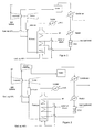
Figure 1 is a schematic process diagram which illustrates one embodiment of the invention in which: Air is compressed in the compressor of the gas turbine and fed to an oxidation reactor in which it is reacted. The gaseous stream from the reactor is condensed to remove condensibles, heated and then reacted in a catalytic combustion unit. Steam or gas is heated in the indirect heater and then added to the catalytically combusted gaseous stream prior to it being heated in an indirect heater. Fuel and air preheated in the indirect heater are fed to the heater to provide a heat source. The resulting hot gaseous stream is then contacted with a clean fuel and with make-up air from the compressor discharge and reacted in a direct-fired combustor to generate the desired gas temperature. The combustor off-gas is then fed to the turbine from which power is recovered. The hot vent gases from the turbine are cooled to recover heat and then discharged to atmosphere. -
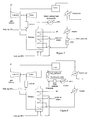
Figure 2 is a schematic diagram of another alternative embodiment of the invention in which: Air is compressed in the compressor of the gas turbine then further compressed in a booster compressor. The compressed air is fed to an oxidation reactor in which it is reacted. The gaseous stream from the reactor is condensed to remove condensibles, heated and then reacted in a catalytic combustion unit. Steam or gas is heated in the indirect heater and then added to the catalytically combusted gaseous steam prior to its being heated in an indirect heater. Fuel and air are preheated in the indirect heater then fed to the heater to provide a heat source. The resulting hot gaseous stream is then contacted with a clean fuel and with make-up air from the compressor discharge and reacted in a direct-fired combustor to generate the desired gas temperature. The combustor off-gas is then fed to the turbine from which power is recovered. The hot vent gases from the turbine are cooled to recover heat and then discharged to atmosphere. -
Figure 3 is a schematic diagram of another alternative embodiment of the invention in which: Air is compressed in the compressor of the gas turbine and fed to an oxidation reactor in which it is reacted. The gaseous stream from the reactor is condensed to remove condensibles, heated then reacted in a catalytic combustion unit. The gaseous stream is cooled and treated, for example by a scrubber to remove reactive components such as HBr and Br2 and then compressed in a booster compressor. The booster compressor is used to maintain the required pressure of the gaseous stream from the reactor through gas treatment to the turbine. Steam or gas is heated in the indirect heater and added to the treated and reheated gaseous stream prior to it being heated in an indirect heater. The resulting hot gaseous stream is then contacted with a clean fuel and with make-up air from the compressor discharge and reacted in a direct-fired combustor to generate the desired gas temperature. The combustor off-gas is then fed to the turbine from which power is recovered. The hot vent gases from the turbine are cooled to recover heat and then discharged to atmosphere. -
Figure 4 is a schematic diagram of another alternative embodiment of the invention in which: Air is compressed in the compressor of the gas turbine and further compressed in a booster compressor. The compressed air is fed to an oxidation reactor in which it is reacted. The gaseous stream from the reactor is condensed to remove condensibles, heated and then reacted in a catalytic combustion unit. Steam or gas, fed under flow or pressure control from the feed to the turbine, is heated in the indirect heater and then added to the catalytically combusted gaseous stream prior to being heated in an indirect heater. Fuel and air are preheated in the indirect heater then fed to the heater to provide a heat source. The resulting hot gaseous stream is then contacted with a clean fuel and with make-up air from the compressor discharge and reacted in a direct-fired combustor to generate the desired gas temperature. The combustor off-gas is then fed to the turbine from which power is recovered. The hot vent gases from the turbine are further cooled to recover heat and then discharged to atmosphere. -
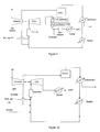
Figure 5 is a schematic diagram of another alternative embodiment of the invention in which: Air is compressed in the compressor of the gas turbine, then fed to an oxidation reactor in which it is reacted. The gaseous stream from the reactor is condensed to remove condensibles, heated and reacted in a catalytic combustion unit. Steam or gas is added to the gaseous stream, contacted with a clean fuel and with make-up air from the compressor discharge and reacted in a direct-fired combustor to generate the desired gas temperature. The combustor off-gas is then fed to the turbine from which power is recovered. The hot vent is further cooled to recover heat and then discharged to atmosphere. -
Figure 6 is a schematic diagram of another alternative embodiment of the invention in which:Figure 1 is modified by interchanging the hot vent gases from the turbine with the feed to the purification plant to displace the high pressure steam requirement from that duty. -
Figure 7 is a schematic diagram of another alternative embodiment of the invention in which:Figure 1 is modified by using the hot vent gases from the turbine to raise steam, which can be high temperature steam (for example 300- 500 degC) -
Figure 8 is a schematic diagram of another alternative embodiment of the invention in which:Figure 1 is modified by adding a combustion unit downstream of the LP Turbine. Additionally ammonia injection together with a NOx reduction catalyst is shown. The catalytic combustion unit inFigure 1 that was downstream of the "Heater" has been removed. -
Figure 9 is a schematic diagram of another alternative embodiment of the invention in which:Figure 8 is depicted with the furnace removed. -
Figure 10 is a schematic diagram of another alternative embodiment of the invention in which:Figure 5 is modified by removing the CCU unit. - In any of these configurations a generator can be attached to the turbine. The net power generated can be used to offset the power requirement of the PTA plant. Surplus power can be exported from the plant.
- The present invention can be characterized by a method for recovering power from an oxidation reaction producing a gaseous stream, the reaction being conducted in a continuous oxidation reactor fed with gaseous oxidant, comprising:
- (a) heating the gaseous stream to a temperature of at least 800°C;
- (b) feeding the gaseous stream to a gas turbine comprising a turbine coupled to a compressor, where the compressor compresses the gaseous oxidant fed to the reactor.
- Gas can be added to the gaseous stream prior to, or simultaneously with, feeding the gaseous stream to the turbine. The mass flow of the gas added to the gaseous stream can be in the range of from about 0% to about 25% of the mass flow of the gaseous stream prior to addition of the gas, for example from about 6% to about 15%. The gas added to the gaseous stream can be steam or air. The gaseous stream can be heated to a temperature in the range of from 800°C to about 1300°C, for example 800°C to about 1100°C, or suitably about 1050°C. An expander or booster compressor can be provided downstream of the gas turbine compressor on the gaseous oxidant inlet to the oxidation reactor. A heater can be provided to heat the gaseous stream and a booster compressor can be provided downstream of the oxidation reactor and upstream of the heater. The gaseous stream can be heated with a direct heater or an indirect heater. The heater can be an interchanger. The gaseous stream can be heated with a catalytic combustion unit prior to heating with a direct heater, an indirect heater or an interchanger. The gaseous stream can be treated with a scrubber. The process can further comprise generating steam from the gaseous stream after step (b). The process can further comprise generating electricity from the gaseous stream after step (b). The can further comprise removing CO and NOx from the gaseous stream after step (b).
- Another embodiment of the present invention can be characterized by a method of monitoring power recovery from an oxidation reaction producing a gaseous stream, the reaction being conducted in a continuous oxidation reactor fed with gaseous oxidant, comprising:
- (a) heating the gaseous stream to a temperature of at least 800°C;
- (b) feeding the gaseous stream to the turbine stage of a gas ICOCGT comprising a turbine coupled to a compressor, where the compressor compresses the gaseous oxidant fed to the reactor;
- (c) monitoring the pressure at the turbine stage of the ICOCGT;
- (d) maintaining the pressure within the turbine stage of the ICOCGT within a pressure range above a minimum value corresponding to the power demand of the compressor to compress the gaseous oxidant feed to an oxidation reactor and below a maximum value set by the power or pressure limits of the gas turbine by adding gas to the gaseous stream.
- The flow of the added gas can be varied to control the pressure at the turbine stage of the gas turbine and the power output of the turbine stage. Gas can be added to the gaseous stream prior to, or simultaneously with, feeding the gaseous stream to the turbine. The mass flow of the gas added to the gaseous stream can be in the range of from about 0% to about 25% of the mass flow of the gaseous stream prior to addition of the gas, for example from about 6% to about 15%. The gas added to the gaseous stream can be steam or air. The gaseous stream can be heated to a temperature in the range of from 800°C to about 1300°C, for example 800°C to about 1100°C, or suitably about 1050°C. An expander or booster compressor can be provided downstream of the gas turbine compressor on the gaseous oxidant inlet to the oxidation reactor. A heater can be provided to heat the gaseous stream and a booster compressor can be provided downstream of the oxidation reactor and upstream of the heater. The gaseous stream can be heated with a direct heater or an indirect heater. The heater can be an interchanger. The gaseous stream can be heated with a catalytic combustion unit prior to heating with a direct heater, an indirect heater or an interchanger. The gaseous stream can be treated with a scrubber. The process can further comprise generating steam from the gaseous stream after step (d). The process can further comprise generating electricity from the gaseous stream after step (d). The can further comprise removing CO and NOx from the gaseous stream after step (d).
- Another embodiment of the present invention can be characterized by a continuous reactor for an oxidation reaction producing a gaseous stream, the reactor comprising:
- (a) a vessel comprising an oxidant inlet and a gaseous stream outlet; and
- (b) a power recovery system connected to the gaseous stream outlet comprising:
- (b1) a heater for heating the gaseous stream connected downstream of the gaseous stream outlet; and
- (b2) a gas turbine connected downstream of the heater comprising a turbine coupled to a compressor, where the compressor is connected to the oxidant inlet such that, when the reactor is in use, the compressor compresses the gaseous oxidant fed to the reactor.
- Prior to, or simultaneously with, feeding the gaseous stream to the turbine, a gas (for example steam or air) can be added to the gaseous stream. In the reactor of the invention, therefore, the power recovery system can comprise a gas inlet for adding gas to the gaseous stream. The heater can be a direct heater or an indirect heater. A catalytic combustion unit can be provided upstream of the heater. A scrubber can be provided between the catalytic combustion unit and the heater. The power recovery system can further comprise an expander or booster compressor downstream of the gas turbine compressor on the gaseous oxidant inlet to the oxidation reactor. The power recovery system can further comprise a booster compressor downstream of the oxidation reactor and upstream of the heater. The power recovery system can further comprise generating steam from the gaseous stream after step (b2). The power recovery system can further comprise generating electricity from the gaseous stream after step (b2). The power recovery system can further comprise removing CO and NOx from the gaseous stream after step (b2).
- Another embodiment of the present invention can be characterized by a process of oxidizing a precursor to an aromatic carboxylic acid or ester thereof in a liquid phase reaction mixture, whereby energy is recovered from the oxidation reaction, comprising:
- (a) contacting one or more precursors of the aromatic carboxylic acid with an oxidant, in the presence of a catalyst and a liquid phase solvent, in a continuous oxidation reactor fed with gaseous oxidant to produce aromatic carboxylic acid and a gaseous stream;
- (b) heating the gaseous stream to a temperature of at least 800°C;
- (c) feeding the gaseous stream to a gas turbine comprising a turbine coupled to a compressor, where the compressor compresses the gaseous oxidant fed to the reactor.
- Gas can be added to the gaseous stream prior to, or simultaneously with, feeding the gaseous stream to the turbine. The mass flow of the gas added to the gaseous stream can be in the range of from about 0% to about 25% of the mass flow of the gaseous stream prior to addition of the gas, for example from about 6% to about 15%. The gas added to the gaseous stream can be steam or air. The gaseous stream can be heated to a temperature in the range of from 800°C to about 1300°C, for example 800°C to about 1100°C, or suitably about 1050°C. An expander or booster compressor can be provided downstream of the gas turbine compressor on the gaseous oxidant inlet to the oxidation reactor. A heater can be provided to heat the gaseous stream and a booster compressor can be provided downstream of the oxidation reactor and upstream of the heater. The gaseous stream can be heated with a direct heater or an indirect heater. The heater can be an interchanger. The gaseous stream can be heated with a catalytic combustion unit prior to heating with a direct heater, an indirect heater or an interchanger. The gaseous stream can be treated with a scrubber. The process can further comprise generating steam from the gaseous stream after step (c). The process can further comprise generating electricity from the gaseous stream after step (c). The process can further comprise removing CO and NOx from the gaseous stream after step (c).
- Another embodiment of the present invention can be characterized by a method for raising power from fuel using the gas turbine. This power generated can be used to offset the plant power requirement. However, more power can be raised than is required for the PTA plant itself. Surplus power generated from the gas turbine can be exported to another chemical plant or to a utility company.
- Another embodiment of the present invention can be characterized by a method for heating feeds to the Purification plant hydrogenation reactor, for example this can be accomplished by either:
- (a) direct heat exchange, namely using the hot turbine exhaust gas to directly heat the Purification plant hydrogenation reactor feed stream;
- (b) using the hot turbine exhaust gas to raise HP steam. The HP steam is then used to heat the Purification plant hydrogenation reactor feed stream.
- An Internal Combustion Open Cycle Gas Turbine (ICOCGT), as disclosed in API 616 Gas Turbines for the Petroleum, Chemical and Gas Industry Services, comprises a compressor, a combustor and a turbine and is optimized to generate power. An embodiment of the present invention utilizes an ICOCGT to beneficially recover power from the gaseous stream produced by an oxidation reaction.
- The compressor stage of the ICOCGT compresses the oxidant feed to the reactor (at greater than atmospheric pressure) thereby at least partially offsetting the cost of providing the high temperature and pressure reaction conditions in the reactor.
- The turbine stage of the ICOCGT expands the heated gaseous stream from the oxidation reactor recovering energy to power the compressor and a hot gas stream, for example to raise steam downstream of the ICOCGT. The net power generated can be used to offset the power requirement of the PTA plant. Surplus power can be exported from the plant.
- Another embodiment of the invention can be characterized by improved control of the power recovery system. The inventors have discovered that the performance of the ICOCGT can be improved by feeding gas (for example steam or air) to the gaseous stream to modulate the flow of gas to the turbine relative to the compressor discharge flow in order to compensate for the consumption of oxidant in the reactor. This embodiment of the present invention therefore provides a convenient method for optimising the power recovery by monitoring the pressure at the turbine stage of the gas turbine. Steam can be utilised in this method because steam is readily available and is usually a by-product of the reaction process.
- In another embodiment of the present invention an expander or booster compressor can be provided downstream of the gas turbine compressor on the oxidant inlet to the oxidation reactor or downstream of the oxidation reactor to adjust the gas turbine compressor discharge to match the optimum pressure of gaseous oxidant into the reactor. Together, the modulation of steam flow into the gaseous stream and the expander or booster compressor enables the use of an ICOCGT coupled to a chemical reactor, thereby allowing the reactor and gas turbine operations to be optimised independently. This embodiment therefore allows a standard gas turbine, which may not itself have optimum properties for the power recovery system, to be optimally integrated for efficient power recovery.
- These, and other aspects of the invention, are described in detail below.
- Prior to heating the gaseous stream or mixing the gaseous stream with steam, solvent in the gaseous steam (for example acetic acid in TA production) can be condensed, for example using separation apparatus such as a distillation column or overhead condensers. Usually, most of the condensate is refluxed to the reactor, with some of the condensate being withdrawn to control reactor water concentration (two moles of water are formed per mole of PX reacted in TA production).
- When it leaves the reactor, the gaseous stream typically has a temperature from 150 to 220°C and a pressure from 600 kPa to 2500 kPa. The temperature and pressure of the reactor can be selected to optimize the operation of the reactor and the downstream processes.
- Optionally, to optimize the temperature and pressure of the gaseous stream leaving the reactor it can be necessary to boost the gaseous stream pressure in an additional compressor.
- The gaseous stream leaving the reactor can be heated to at least 800°C with any suitable heater, such as a direct heater of the gaseous stream, such as a combustor fuelled for example with natural gas or fuel oil, or an indirect heater of the gaseous stream, such as a furnace fuelled for example with natural gas or fuel oil. In one embodiment, fuel and oxidant (for example from the reactor oxidant feed) are mixed with the gaseous stream in a combustor and burnt in order to raise the temperature of the gaseous stream directly. Typically, however, a furnace heats the gaseous stream indirectly, i.e. fuel and oxidant (for example air) are burnt in the furnace without mixing with the gaseous stream and the gaseous stream is heated by indirect heat exchange as it passes thorough the furnace. Indirect heating can be advantageous as it does not require additional oxidant to be fed above atmospheric pressure to the gaseous stream to burn the fuel. Instead indirect heating can involve combustion of fuel using atmospheric air.
- Optionally, other auxiliary heaters can be used in addition to the heater for heating the gaseous stream. Prior to heating (i.e. upstream of the heater), the gaseous stream can be fed to a catalytic combustion unit (CCU). CCUs are typically used for environmental reasons to remove organic compounds and reactor by-products in the gaseous stream and operate by flameless oxidation of the organic compounds etc (e.g. MeBr). Typically, the gaseous stream leaving the CCU has a temperature of from about 450°C to about 600°C. Optionally, the gaseous stream can be heated with an interchanger, i.e. a heat exchanger that transfers heat between a process stream and the gaseous stream.
- The temperature of the gaseous stream entering the CCU can be about 250°C to about 400°C, for example about 300°C, to ensure stable combustion in the CCU. Prior to treatment with the CCU, the gaseous stream can be heated from about 200°C to about 350°C, for example from about 300°C to about 350°C. A steam heater provided upstream of the CCU can be used to achieve such heating. The steam heater can use steam produced as a by-product of the oxidation reaction to heat the gaseous stream.
- Following the CCU, optionally the gas can be treated, for example by scrubbing (for example by use of a scrubber), to remove reactive components such as HBr and Br2 prior to feeding to a gas heater. One way of heating the gaseous feed stream to the CCU can be to interchange heat with the CCU exit stream.
- Prior to, or simultaneously with, feeding the gaseous stream to the turbine inlet, gas (for example steam or air) can be added to the gaseous stream. In the reactor of the invention, therefore, the power recovery system can comprise a gas inlet for adding gas to the gaseous stream. The gas, for example steam or air, can be added to the gaseous stream before or after the step of heating the gaseous stream (or where heating involves more than one step between steps). The gas can be added before the step of heating of the gaseous stream (i.e. upstream of the heater). The gaseous stream, immediately prior to being fed to the turbine, has a temperature of at least 800°C, for example in the range of from 800°C to about 1300°C, or 800°C to about 1100°C, or suitably about 1050°C.
- The gas can be added to the gaseous stream to modulate the mass flow of gas to the turbine to compensate for the oxidant consumed in the oxidation reactor. To optimise the economic performance additional gas can be further added to the gaseous stream beyond that required to compensate for the consumption of oxidant in the reactor. This can be advantageous, as it allows the power recovered in the gas turbine to be increased. Calculation of the gas turbine characteristics can allow determination of the additional gas added to the gaseous stream; the upper value set by the power or pressure limits of the gas turbine and the lower value set by generating sufficient power to drive the compressor. Typically, however, the mass flow of gas added to the gaseous stream can be in the range of from about 0% to about 25%, for example about 6% to about 15%, of the mass flow of the gaseous stream (prior to addition of gas).
- Alternatively, the additional flow of gas can allow the temperature of gaseous stream flowing into the turbine to be lowered (while achieving equivalent power recovery from the gas turbine), thus reducing the temperature to which the gaseous stream must be heated and saving fuel costs. In general, the power recovery by the gas turbine can be optimised by the selection of the appropriate gaseous stream flow into the gas turbine (which can be modulated by the addition of steam or air) and the temperature of the gaseous stream into the turbine.
- As used herein, a "gas turbine" refers to a standard gas turbine, for example those described and listed in API 616 Gas Turbines for the Petroleum, Chemical and Gas Industry Services and Turbomachinery International Handbook 2006, vol. 46, no. 6, comprising a compressor coupled to a turbine by one or more shafts. The turbine is connected to the gaseous stream downstream of the heater. The compressor is connected to the oxidant inlet of the reactor and compresses the gaseous oxidant fed to the reactor. Typically, the turbine power will be greater than the compressor power consumption.
- Because compressing the oxidant (which is used in significant quantities in the reactor) is a costly step in the reaction process, it is advantageous that this cost be at least partially offset by power recovery from the gaseous stream.
- To minimise the capital cost of the power recovery system, the gas turbine used in the invention can be of a standard design and construction with only minor modification. Generally, the present invention selects a gas turbine designed for the temperatures, pressures and flow rates of the gaseous stream, and the power requirements of the compressor for compressing the oxidant feed. An expander or booster compressor can be provided downstream of the gas turbine compressor on the gaseous oxidant feed. This expander or compressor allows adjustment of the turbine compressor discharge to match the optimum pressure of gaseous oxidant into the reactor in order to assist with the integration of the gas turbine with the remaining components of the power recovery system and the reactor, and to allow optimisation of the power recovery. This embodiment can be particularly advantageous, as it enables de-coupling of the requirements of the gas turbine and reactor, thereby allowing the reactor and gas turbine operations to be optimised independently. Alternatively, a booster compressor can be located downstream of the oxidation reactor and upstream of the heater to adjust and optimise the pressure of the gaseous stream into the turbine.
- Gas (for example steam or air) can be added to the gaseous stream, prior to, or simultaneously with, feeding the gaseous stream to the turbine inlet. In one embodiment, gas can be added to the gaseous stream prior to feeding the gaseous stream to the turbine inlet (i.e. upstream of the turbine) and, therefore, in the power recovery system of the invention, the steam inlet is upstream of the turbine. This can be advantageous to match the compressor and turbine duties, enabling the use of a standard gas turbine.
- One technical issue of the present invention is ensuring that the off gas emissions meet increasingly tight NOx and CO legislative specifications. With respect to the turbine burner design, in general, higher combustion temperature and longer residence time encourages good CO combustion at the expense of increased production of NOx. The converse also applies - low combustion temperature or, residence time leads to low NOx but also to high CO. Where unacceptably high CO or NOx is left in the offgas the gaseous stream would need to be treated. Finding a suitable design point gives significant risk of the operating plant failing to meet at least one of its environmental operating targets either through inaccuracy of the design to exacting requirements or due to need of the PTA plant for operational flexibility.
- To mitigate this risk the gaseous stream downstream of the turbine can be treated as follows:
- 1. The gaseous stream is fed to a combustion unit (catalytic or non-catalytic) to remove CO as conventionally known in the art.
- 2. Following the combustion unit, ammonia can be injected to the gas stream and directed over a catalyst bed to reduce the NOx to N2 gas. This stream can then be discharged to atmosphere meeting relevant enviromnental standards.
- Either, or both, of these schemes may be used depending upon the local environmental standards required.
- The reactor is a continuous flow reactor, meaning a reactor in which reactants are introduced and mixed and products withdrawn simultaneously in a continuous manner, as opposed to a batch-type reactor. In this invention a standard oxidation reactor, for example as disclosed in
US 7,153,480 , can be used. Standard reactants and operating conditions, for example as disclosed inUS 7,153,480 , can also be used. - The invention is suitable for any oxidation reaction producing a gaseous stream, i.e. gaseous reaction products. For example, oxidation reactions include cyclohexane oxidation, PX oxidation to TA or dimethyl terephthalate, metaxylene oxidation to isophthalic acid etc. However, the oxidation of PX to TA is of particular interest in the invention.
- The oxidant in the invention can be molecular oxygen, for example air (including oxygen-depleted air and oxygen enriched air).
- Oxidation reactions are typically exothermic and heat can be removed, in order to control the reaction temperature, by removing the volatile components, condensing them, and returning the condensate to the reactor. Alternatively or additionally, the heat of reaction can be removed from the reaction by heat exchange with a heat-accepting fluid, according to conventional techniques known to those skilled in the art.
- As mentioned above, the reactor is generally operated in a continuous mode. By carrying out the process in a continuous flow reactor, the residence time for the reaction can be made compatible with the attainment of conversion of the precursors to the desired product without significant production of degradation products.
- The gaseous stream can be heated to a temperature in the range of from 800°C to about 1300°C, for example 800°C to about 1100°C, or suitably about 1050°C.
- As used herein, reference to the production of a carboxylic acid includes reference to the production of its ester. As will be evident to the skilled person, whether a carboxylic acid or its ester is produced will depend on the conditions in the reactor and/or the conditions used to purify the products.
- As used herein, "aromatic carboxylic acid precursor" or "precursor" means an organic compound, preferably a hydrocarbon, capable of being oxidised to a specific aromatic carboxylic acid in a majority yield in the presence of selective oxidising conditions. An example of a terephthalic acid precursor is paraxylene. An example of an isophthalic acid precursor is metaxylene.
- The present invention can comprise feeding solvent, oxidant, precursor and catalyst into an oxidation reactor that is maintained at a temperature in the range of from about 150°C to about 250°C, for example about 175°C to about 225°C, and a pressure in the range of from about 100 kPa to about 5000 kPa, for example about 1000 kPa to about 3000 kPa.
- The oxidation reaction can be carried out in the presence of an oxidation catalyst. The catalyst can be substantially soluble in the reaction medium comprising solvent and the aromatic carboxylic acid precursor(s). The catalyst can comprise one or more heavy metal compounds, for example cobalt and/or manganese compounds, and can optionally include an oxidation promoter. For instance, the catalyst can take any of the forms that have been used in the liquid phase oxidation of aromatic carboxylic acid precursors such as terephthalic acid precursor(s) in aliphatic aromatic carboxylic acid solvent, for example bromides, bromoalkanoates or alkanoates (usually C1-C4 alkanoates such as acetates) of cobalt and/or manganese. Compounds of other heavy metals such as vanadium, chromium, iron, molybdenum, a lanthanide such as cerium, zirconium, hafnium, and/or nickel can be used instead of, or additional to, cobalt and/or manganese. Advantageously, the catalyst system can include manganese bromide (MnBr2) and/or cobalt bromide (CoBr2). The oxidation promoter, where employed, can be in the form of elemental bromine, ionic bromide (for example HBr, NaBr, KBr, NH4Br) and/or organic bromide (for example bromobenzenes, benzyl-bromide, mono- and di-bromoacetic acid, bromoacetyl bromide, tetrabromoethane, ethylene-dibromide, etc.).
- Any suitable solvent in which the oxidation reaction can take place can be used. Where the oxidation reaction is the catalytic liquid phase oxidation of a precursor to produce aromatic carboxylic acid, the solvent can be an aliphatic monocarboxylic acid having from 2 to 6 carbon atoms, for example, the solvent can be acetic acid. Acetic acid can be particularly useful as the solvent since it is relatively resistant to oxidation in comparison with other solvents and increases the activity of the catalytic pathway.
- The reaction can be effected by heating and pressurising the precursor, catalyst and solvent mixture followed by introduction of the oxidant into the reactor via the oxidant inlet.
- The effluent, i.e. reaction product, from the oxidation reactor can be a slurry of aromatic carboxylic acid crystals which are recovered from the slurry by filtration and subsequent washing. They can thereafter be fed to a separate purification step or directly to a polymerization process, for example, the main impurity in crude TPA is 4-carboxybenzaldehyde (4-CBA), which is incompletely oxidized paraxylene, although other oxidation products and precursors to terephthalic acid such as p-tolualdehyde and p-toluic acid can also be present as contaminants.
- A method of starting the power recovery system can be to start the gas turbine using its normal starting device (such as a starter motor), obeying all the normal protocols for internal combustion gas turbine operation. This stage of start up uses a plant bypass shortcutting the whole reactor system and heating train (comprising furnace etc.). Once the gas turbine is in steady state at part-load, air is gradually passed through the booster compressor or expander (if present), and heating train (comprising furnace etc.) and returned to the gas turbine combustor and the expansion stage of the gas turbine. Similarly, if a booster compressor is located upstream of the combustor, this is started once the gas turbine is in steady state at part load. This stage of start up uses an air bypass round the oxidation reactor. After all the air from the compressor of the gas turbine is being fed through the heating train the first bypass is fully closed. Now air is fed to the oxidation reactor in order to initiate the reaction. Steam is fed to the heating train to maintain the gas turbine output power to the desired level. The proportion of air fed to the reactor is controlled by modulating the reactor bypass valve. The power recovery system is fully online once the reactor bypass is closed.
- On oxidation reactor trip, the air flow from the compressor stage is diverted through the reactor bypass to the expansion stage of the gas turbine. The reactor can be restarted readily from this condition. Shutdown of the gas turbine can also proceed from this condition.
- The term "comprising" encompasses "including" as well as "consisting" for example a composition "comprising" X may consist exclusively of X or may include something additional for example X + Y.
- The term "about" in relation to a numerical value x means, for example, x±10%.
- It will be understood that the invention has been described by way of example only and modifications can be made whilst remaining within the scope and spirit of the invention.
- The invention also encompasses the following embodiments.
- 1. A method for recovering power from an oxidation reaction producing a gaseous stream, the reaction being conducted in a continuous oxidation reactor fed with gaseous oxidant, comprising:
- (a) heating the gaseous stream to a temperature of at least 800°C;
- (b) feeding the gaseous stream to a turbine stage of a gas turbine comprising a turbine coupled to a compressor, where the compressor compresses the gaseous oxidant fed to the reactor.
- 2. The method of embodiment 1 wherein prior to, or simultaneously with, feeding the gaseous stream to the turbine, gas is added to the gaseous stream.
- 3. The method of embodiment 1 or claim 2 wherein an expander or booster compressor is provided downstream of the gas turbine compressor on the gaseous oxidant inlet to the oxidation reactor.
- 4. The method of any one of embodiment 1 to 3 wherein a heater is provided to heat the gasesous stream and a booster compressor is provided downstream of the oxidation reactor and upstream of the heater.
- 5. A method of monitoring power recovery from an oxidation reaction producing a gaseous stream, the reaction being conducted in a continuous oxidation reactor fed with gaseous oxidant, comprising:
- (a) heating the gaseous stream to a temperature of at least 800°C;
- (b) feeding the gaseous stream to a turbine stage of a gas ICOCGT comprising a turbine coupled to a compressor, where the compressor compresses the gaseous oxidant fed to the reactor;
- (c) monitoring the pressure at the turbine stage of the ICOCGT;
- (d) maintaining the pressure within the turbine stage of the ICOCGT within a pressure range above a minimum value corresponding to the power demand of the compressor to compress the gaseous oxidant feed to an oxidation reactor and below a maximum value set by the power or pressure limits of the gas turbine by adding gas to the gaseous stream.
- 6. The method of any one of embodiment 2 to 5 wherein the mass flow of the gas added to the gaseous stream is in the range of from about 0% to about 25% of the mass flow of the gaseous stream prior to addition of the gas.
- 7. The method of any one of embodiment 2 to 6 wherein the mass flow of the gas added to the gaseous stream is in the range of from about 6% to about 15% of the mass flow of the gaseous stream prior to addition of the gas.
- 8. The method of any one of embodiment 2 to 7 wherein the gas is steam or air.
- 9. The method of any one of embodiments 1 to 8 comprising heating the gaseous stream to a temperature in the range of from 800°C to about 1350°C.
- 10. The method of embodiment 9 comprising heating the gaseous stream to a temperature in the range of from 800°C to about 1100°C.
- 11. The method of any one of embodiments 1 to 8 comprising heating the gaseous stream to a temperature of about 1050°C.
- 12. The method of any one of embodiments 1 to 11 wherein the gaseous stream is heated with a direct heater.
- 13. The method of any one of embodiments 1 to 11 wherein the gaseous stream is heated with an indirect heater.
- 14. The method of embodiment 12 wherein the gaseous stream is heated with a catalytic combustion unit prior to heating with a direct heater.
- 15. The method of embodiment 13 wherein the gaseous stream is heated with a catalytic combustion unit prior to heating with an indirect heater.
- 16. The method of any one of embodiments 1 to 15 wherein the gaseous stream is heated with an interchanger.
- 17. The method of any one of embodiments 1 to 16 wherein the gaseous stream is treated by a scrubber.
- 18. A continuous reactor for an oxidation reaction producing a gaseous stream, the reactor comprising:
- (a) a vessel comprising an oxidant inlet and a gaseous stream outlet; and
- (b) a power recovery system connected to the gaseous stream outlet comprising:
- (b1) a heater for heating the gaseous stream connected downstream of the gaseous stream outlet; and
- (b2) a gas turbine connected downstream of the heater comprising a turbine coupled to a compressor, where the compressor is connected to the oxidant inlet such that, when the reactor is in use, the compressor compresses the gaseous oxidant fed to the reactor.
- 19. The reactor of embodiment 18 wherein the power recovery system comprises a gas inlet for adding gas to the gaseous stream.
- 20. The reactor of embodiment 18 of embodiment 19 wherein the heater is a direct heater.
- 21. The method of embodiment 18 or embodiment 19 wherein the heater is an indirect heater.
- 22. The reactor of any one of embodiments 18 to 21 wherein a catalytic combustion unit is provided upstream of the heater.
- 23. The reactor of embodiment 22 wherein a scrubber is provided between the catalytic combustion unit and the heater.
- 24. The reactor of any one of embodiments 18 to 23 wherein the power recovery system comprises an expander or booster compressor provided downstream of the gas turbine compressor on the gaseous oxidant inlet to the oxidation reactor.
- 25. The reactor of any one of embodiments 18 to 24 wherein the power recovery system comprises a booster compressor downstream of the oxidation reactor and upstream of the heater.
- 26. A process of oxidising a precursor to an aromatic carboxylic acid or ester thereof in a liquid phase reaction mixture, whereby energy is recovered from the oxidation reaction, comprising:
- (a) contacting one or more precursors of the aromatic carboxylic acid with an oxidant, in the presence of a catalyst and a liquid phase solvent, in a continuous oxidation reactor fed with gaseous oxidant to produce aromatic carboxylic acid and a gaseous stream;
- (b) heating the gaseous stream to a temperature of at least 800°C;
- (c) feeding the gaseous stream to a gas turbine comprising a turbine coupled to a compressor, where the compressor compresses the gaseous oxidant fed to the reactor.
- 27. The process of embodiments 26 further comprising (d) generating steam from the gaseous stream after step (c).
- 28. The process of embodiment 26 further comprising (d) generating electricity from the gaseous stream after step (c).
- 29. The process of embodiment 26 further comprising (d) removing CO and NOx from the gaseous stream after step (c).
- 30. The method of embodiment 1 further comprising (c) generating steam from the gaseous stream after step (b).
- 31. The method of embodiment 1 further comprising (c) generating electricity from the gaseous stream after step (b).
- 32. The method of embodiment further comprising (c) removing CO and NOx from the gaseous stream after step (b).
- 33. The method of embodiment 5 further comprising (e) generating steam from the gaseous stream after step (b).
- 34. The method of embodiment 5 further comprising (e) generating electricity from the gaseous stream after step (b).
- 35. The method of embodiment 5 further comprising (e) removing CO and NOx from the gaseous stream after step (b).
- 36. The method of embodiment 5 further comprising (e) heating a feed to another reactor by direct heat exchange with the gaseous feed out of the gas turbine.
- 37. The method of embodiment 5 further comprising (e) heating a feed to another reactor by using the gaseous stream out of the gas turbine to raise high pressure steam.
- 38. The reactor of embodiment 18 wherein the power recovery system further comprises (b3) generating steam from the gaseous stream after step (b2).
- 39. The reactor of embodiment 18 wherein the power recovery system further comprises (b3) generating electricity from the gaseous stream after step (b2).
- 40. The reactor of embodiment 18 wherein the power recovery system further comprises (b3) removing CO and NOx from the gaseous stream after step (b2).
Claims (20)
- A method for recovering power from an oxidation reaction producing a gaseous stream, the reaction being conducted in a continuous oxidation reactor fed with gaseous oxidant, comprising:(a) heating the gaseous stream to a temperature of at least 800°C;(b) feeding the gaseous stream to a turbine stage of a gas turbine comprising a turbine coupled to a compressor, where the compressor compresses the gaseous oxidant fed to the reactor.
- The method of claim 1 wherein prior to, or simultaneously with, feeding the gaseous stream to the turbine, gas is added to the gaseous stream.
- The method of claim 1 or claim 2 wherein an expander or booster compressor is provided downstream of the gas turbine compressor on the gaseous oxidant inlet to the oxidation reactor.
- The method of any one of claims 1 to 3 wherein a heater is provided to heat the gaseous stream and a booster compressor is provided downstream of the oxidation reactor and upstream of the heater.
- The method of any one of claims 2 to 4 wherein the mass flow of the gas added to the gaseous stream is in the range of from about 0% to about 25% of the mass flow of the gaseous stream prior to addition of the gas, optionally wherein the mass flow of the gas added to the gaseous stream is in the range of from about 6% to about 15% of the mass flow of the gaseous stream prior to addition of the gas.
- The method of any one of claims 2 to 5 wherein the gas is steam or air.
- The method of any one of claims 1 to 6 comprising heating the gaseous stream to a temperature in the range of from 800°C to about 1350°C, optionally comprising heating the gaseous stream to a temperature in the range of from 800°C to about 1100°C, optionally comprising heating the gaseous stream to a temperature of about 1050°C.
- The method of any one of claims 1 to 7 wherein the gaseous stream is heated with a direct heater, optionally wherein the gaseous stream is heated with an indirect heater.
- The method of claim 8 wherein the gaseous stream is heated with a catalytic combustion unit prior to heating with a direct heater, optionally wherein the gaseous stream is heated with a catalytic combustion unit prior to heating with an indirect heater.
- The method of any one of claims 1 to 9 wherein the gaseous stream is heated with an interchanger.
- The method of any one of claims 1 to 10 wherein the gaseous stream is treated by a scrubber.
- A continuous reactor for an oxidation reaction producing a gaseous stream, the reactor comprising:(a) a vessel comprising an oxidant inlet and a gaseous stream outlet; and(b) a power recovery system connected to the gaseous stream outlet comprising:(b1) a heater for heating the gaseous stream connected downstream of the gaseous stream outlet; and(b2) a gas turbine connected downstream of the heater comprising a turbine coupled to a compressor, where the compressor is connected to the oxidant inlet such that, when the reactor is in use, the compressor compresses the gaseous oxidant fed to the reactor.
- The reactor of claim 12 wherein the power recovery system comprises a gas inlet for adding gas to the gaseous stream.
- The reactor of claim 12 or claim 13 wherein the heater is a direct heater, optionally wherein the heater is an indirect heater.
- The reactor of any one of claims 12 to 14 wherein a catalytic combustion unit is provided upstream of the heater.
- The reactor of claim 15 wherein a scrubber is provided between the catalytic combustion unit and the heater.
- The reactor of any one of claims 12 to 16 wherein the power recovery system comprises an expander or booster compressor provided downstream of the gas turbine compressor on the gaseous oxidant inlet to the oxidation reactor.
- The reactor of any one of claims 12 to 17 wherein the power recovery system comprises a booster compressor downstream of the oxidation reactor and upstream of the heater.
- The method of claim 1 further comprising (c) generating steam from the gaseous stream after step (b), optionally further comprising (c) generating electricity from the gaseous stream after step (b), optionally further comprising (c) removing CO and NOx from the gaseous stream after step (b).
- The reactor of claim 12 wherein the power recovery system further comprises (b3) generating steam from the gaseous stream after step (b2), optionally, wherein the power recovery system further comprises (b3) generating electricity from the gaseous stream after step (b2), optionally wherein the power recovery system further comprises (b3) removing CO and NOx from the gaseous stream after step (b2).
Applications Claiming Priority (3)
| Application Number | Priority Date | Filing Date | Title |
|---|---|---|---|
| GBGB0808200.0A GB0808200D0 (en) | 2008-05-06 | 2008-05-06 | Power recovery |
| US10823308P | 2008-10-24 | 2008-10-24 | |
| EP09742342A EP2384394A2 (en) | 2008-05-06 | 2009-05-06 | Power recovery |
Related Parent Applications (2)
| Application Number | Title | Priority Date | Filing Date |
|---|---|---|---|
| EP09742342.0 Division | 2009-05-06 | ||
| EP09742342A Division EP2384394A2 (en) | 2008-05-06 | 2009-05-06 | Power recovery |
Publications (2)
| Publication Number | Publication Date |
|---|---|
| EP2495405A2 true EP2495405A2 (en) | 2012-09-05 |
| EP2495405A3 EP2495405A3 (en) | 2012-11-21 |
Family
ID=39537335
Family Applications (2)
| Application Number | Title | Priority Date | Filing Date |
|---|---|---|---|
| EP12170077A Withdrawn EP2495405A3 (en) | 2008-05-06 | 2009-05-06 | Power recovery |
| EP09742342A Withdrawn EP2384394A2 (en) | 2008-05-06 | 2009-05-06 | Power recovery |
Family Applications After (1)
| Application Number | Title | Priority Date | Filing Date |
|---|---|---|---|
| EP09742342A Withdrawn EP2384394A2 (en) | 2008-05-06 | 2009-05-06 | Power recovery |
Country Status (13)
| Country | Link |
|---|---|
| US (2) | US20110100007A1 (en) |
| EP (2) | EP2495405A3 (en) |
| JP (1) | JP2011528276A (en) |
| KR (1) | KR20110005300A (en) |
| CN (1) | CN102770626A (en) |
| BR (1) | BRPI0908294A2 (en) |
| CA (1) | CA2723701C (en) |
| DE (1) | DE202009019033U1 (en) |
| GB (1) | GB0808200D0 (en) |
| MX (1) | MX2010012162A (en) |
| RU (1) | RU2548026C2 (en) |
| TW (1) | TWI368685B (en) |
| WO (1) | WO2009136146A2 (en) |
Cited By (1)
| Publication number | Priority date | Publication date | Assignee | Title |
|---|---|---|---|---|
| WO2014189818A1 (en) * | 2013-05-24 | 2014-11-27 | Invista Technologies S.À.R.L. | Power recovery for use in start-up or re-start of a pure terephthalic acid production process |
Families Citing this family (15)
| Publication number | Priority date | Publication date | Assignee | Title |
|---|---|---|---|---|
| US20130255259A1 (en) * | 2008-10-24 | 2013-10-03 | Invista North America S.A R.L. | Power recovery for use in start-up or re-start of a pure terephthalic acid production process |
| PL2488797T3 (en) * | 2009-10-16 | 2016-12-30 | Low emissions direct fired air heater | |
| US8779208B2 (en) | 2012-05-18 | 2014-07-15 | Eastman Chemical Company | Process for reducing emissions of volatile organic compounds from the ketonization of carboxylic acids |
| US10161312B2 (en) * | 2012-11-02 | 2018-12-25 | General Electric Company | System and method for diffusion combustion with fuel-diluent mixing in a stoichiometric exhaust gas recirculation gas turbine system |
| JP6342755B2 (en) * | 2014-09-05 | 2018-06-13 | 株式会社神戸製鋼所 | Compression device |
| DE102016200916A1 (en) | 2016-01-22 | 2017-07-27 | Ferdinand Reif | Gas turbine use in oxidation processes |
| US10280844B2 (en) * | 2016-11-17 | 2019-05-07 | General Electric Company | Control systems for controlling power systems based on fuel consumption and related program products |
| CN108434982A (en) * | 2018-04-28 | 2018-08-24 | 杭州谱育科技发展有限公司 | Cyclohexanone exhaust gas processing device and method |
| KR20210083317A (en) * | 2018-10-29 | 2021-07-06 | 에이알비 파이롤리시스 엘엘씨 | Systems and methods for treating carbonaceous feedstock |
| GB2584712A (en) * | 2019-06-13 | 2020-12-16 | Rolls Royce Plc | A forced air convection apparatus and method for cooling a turbomachine |
| DE102019216624A1 (en) * | 2019-10-29 | 2021-04-29 | Robert Bosch Gmbh | Method for operating a fuel cell system |
| US11774427B2 (en) * | 2019-11-27 | 2023-10-03 | General Electric Company | Methods and apparatus for monitoring health of fuel oxygen conversion unit |
| WO2021188385A1 (en) * | 2020-03-19 | 2021-09-23 | Kellogg Brown & Root Llc | Power augmentation for a gas turbine |
| CN111608805A (en) * | 2020-04-20 | 2020-09-01 | 中国石油化工股份有限公司 | Method for energy recovery of oxidation tail gas in the production of cyclohexanone by oxidation method |
| CN111608806A (en) * | 2020-04-20 | 2020-09-01 | 中国石油化工股份有限公司 | Method and device for recovering tail gas energy in cyclohexanone oxidation production process |
Citations (5)
| Publication number | Priority date | Publication date | Assignee | Title |
|---|---|---|---|---|
| US2833816A (en) | 1954-05-03 | 1958-05-06 | Mid Century Corp | Preparation of aromatic polycarboxylic acids |
| WO1996011899A1 (en) | 1994-10-14 | 1996-04-25 | Amoco Corporation | Process for preparing aromatic carboxylic acids with efficient energy recovery |
| JPH08155265A (en) | 1994-12-08 | 1996-06-18 | Mitsui Petrochem Ind Ltd | Exhaust gas treatment method |
| WO1996039595A1 (en) | 1995-06-05 | 1996-12-12 | Imperial Chemical Industries Plc | Effluent gas treatment |
| US7153480B2 (en) | 2003-05-22 | 2006-12-26 | David Robert Bickham | Apparatus for and method of producing aromatic carboxylic acids |
Family Cites Families (39)
| Publication number | Priority date | Publication date | Assignee | Title |
|---|---|---|---|---|
| GB808200A (en) | 1956-12-10 | 1959-01-28 | British Cellophane Ltd | Improvements in or relating to the manufacture of sheet wrapping materials |
| GB1146292A (en) * | 1965-12-24 | 1969-03-26 | Humphreys & Glasgow Ltd | Process and apparatus for the manufacture of nitric acid |
| GB1216575A (en) * | 1967-07-12 | 1970-12-23 | Chemical Construction Corp | Recovery of power from heated gas streams |
| LU56620A1 (en) * | 1967-08-08 | 1968-11-14 | ||
| FR2116594A5 (en) * | 1970-10-22 | 1972-07-21 | Progil | |
| HU174031B (en) * | 1976-11-09 | 1979-10-28 | Mta Mueszaki Kemiai Kutato Int | Method and apparatus for heat supplying technological processes taking place in closed space |
| US4202168A (en) * | 1977-04-28 | 1980-05-13 | Gulf Research & Development Company | Method for the recovery of power from LHV gas |
| JPS54148178A (en) * | 1978-05-12 | 1979-11-20 | Ishikawajima Harima Heavy Ind Co Ltd | Power recovery from oxydation reaction process waste gas |
| GB2024033B (en) * | 1978-06-28 | 1983-02-23 | Texaco Development Corp | Power recovery from catalyst regeneration gas |
| JPS5688920A (en) * | 1979-12-18 | 1981-07-18 | Ebara Corp | Operating method of power-regenerating turbine |
| US4492085A (en) * | 1982-08-09 | 1985-01-08 | General Electric Company | Gas turbine power plant |
| JPS60219421A (en) * | 1984-04-16 | 1985-11-02 | Mitsubishi Gas Chem Co Inc | Method of recovering power from exhaust gas of oxidizing process |
| JPS62203929A (en) * | 1986-03-04 | 1987-09-08 | Mitsubishi Gas Chem Co Inc | Motorized recovery method from oxidation reactor off-gas |
| FI76866C (en) * | 1987-01-30 | 1988-12-12 | Imatran Voima Oy | MEDICAL EQUIPMENT BRAENSLE DRIVEN GASTURBINANLAEGGNING OCH FOERFARANDE FOER UTNYTTJANDE AV VAERMEENERGIN I NAEMNDA BRAENSLE. |
| SE8702785L (en) * | 1987-07-06 | 1989-01-07 | Asea Stal Ab | SET FOR DESTRUCTION OF UNUSUALED ORGANIC SUBSTANCES |
| JP2996963B1 (en) * | 1998-10-27 | 2000-01-11 | 川崎重工業株式会社 | Fluidized bed drying / classifying equipment |
| DK166377C (en) * | 1989-02-10 | 1993-09-27 | Haldor Topsoe As | PROCEDURE FOR THE REMOVAL OF NITROGEN OXIDES FROM EXHAUST GAS FROM TURBINES |
| US4953479A (en) * | 1989-06-09 | 1990-09-04 | Keller Leonard J | Methacoal integrated combined cycle power plants |
| FI89734C (en) * | 1990-01-04 | 1993-11-10 | Ahlstroem Oy | Method and apparatus for treating gases from gasification or your combustion plants |
| DE4026732A1 (en) * | 1990-08-24 | 1992-02-27 | Huels Chemische Werke Ag | METHOD FOR CLEANING AN OXIDATION EXHAUST GAS WITH ENERGY RECOVERY |
| JPH04334703A (en) * | 1991-05-08 | 1992-11-20 | Mitsubishi Heavy Ind Ltd | Power recovering device of fluidized catalytic cracker |
| GB9200715D0 (en) * | 1992-01-14 | 1992-03-11 | Klavers Hendrick W | Power generation |
| US5375408A (en) * | 1993-07-06 | 1994-12-27 | Foster Wheeler Development Corporation | Combined-cycle power generation system using a coal-fired gasifier |
| US5666823A (en) * | 1996-01-31 | 1997-09-16 | Air Products And Chemicals, Inc. | High pressure combustion turbine and air separation system integration |
| KR20000005733A (en) * | 1998-06-05 | 2000-01-25 | 나까니시 히로유끼 | process for producing aromatic carboxylic acid |
| GB2348695A (en) * | 1999-04-06 | 2000-10-11 | James Engineering | Gas turbines |
| US6205768B1 (en) * | 1999-05-05 | 2001-03-27 | Solo Energy Corporation | Catalytic arrangement for gas turbine combustor |
| JP2001131563A (en) * | 1999-11-08 | 2001-05-15 | Ishikawajima Harima Heavy Ind Co Ltd | Organic waste gasification system |
| US6196000B1 (en) * | 2000-01-14 | 2001-03-06 | Thermo Energy Power Systems, Llc | Power system with enhanced thermodynamic efficiency and pollution control |
| US6765113B2 (en) * | 2000-07-19 | 2004-07-20 | E.I. Du Pont De Nemours And Company | Production of aromatic carboxylic acids |
| NO318619B1 (en) * | 2000-12-29 | 2005-04-18 | Norsk Hydro As | Device for combustion of a carbonaceous fuel, a method for operating said device, and use of said device. |
| JP4118077B2 (en) * | 2002-04-15 | 2008-07-16 | バブコック日立株式会社 | Exhaust gas purification method |
| SE524218C2 (en) * | 2003-01-20 | 2004-07-13 | Alstom Power Sweden Ab | Gas turbine plant and method for controlling load in a gas turbine plant |
| US8631657B2 (en) * | 2003-01-22 | 2014-01-21 | Vast Power Portfolio, Llc | Thermodynamic cycles with thermal diluent |
| JP2004257606A (en) * | 2003-02-25 | 2004-09-16 | Toray Ind Inc | Treatment method of reaction exhaust gas |
| US7162864B1 (en) * | 2003-11-04 | 2007-01-16 | Sandia National Laboratories | Method for control of NOx emission from combustors using fuel dilution |
| US20050256335A1 (en) * | 2004-05-12 | 2005-11-17 | Ovidiu Marin | Providing gases to aromatic carboxylic acid manufacturing processes |
| EP1840354B1 (en) * | 2006-03-28 | 2017-11-29 | Ansaldo Energia IP UK Limited | Method for operating a gas turbine plant and gas turbine plant for carrying out the method |
| US7451591B2 (en) * | 2006-05-08 | 2008-11-18 | Econo-Power International Corporation | Production enhancements on integrated gasification combined cycle power plants |
-
2008
- 2008-05-06 GB GBGB0808200.0A patent/GB0808200D0/en not_active Ceased
-
2009
- 2009-05-05 TW TW098114838A patent/TWI368685B/en not_active IP Right Cessation
- 2009-05-06 JP JP2011507981A patent/JP2011528276A/en active Pending
- 2009-05-06 WO PCT/GB2009/001117 patent/WO2009136146A2/en not_active Ceased
- 2009-05-06 MX MX2010012162A patent/MX2010012162A/en not_active Application Discontinuation
- 2009-05-06 DE DE202009019033.1U patent/DE202009019033U1/en not_active Expired - Lifetime
- 2009-05-06 EP EP12170077A patent/EP2495405A3/en not_active Withdrawn
- 2009-05-06 US US12/990,984 patent/US20110100007A1/en not_active Abandoned
- 2009-05-06 CA CA2723701A patent/CA2723701C/en not_active Expired - Fee Related
- 2009-05-06 RU RU2010149770/04A patent/RU2548026C2/en not_active IP Right Cessation
- 2009-05-06 CN CN2009801262352A patent/CN102770626A/en active Pending
- 2009-05-06 BR BRPI0908294-8A patent/BRPI0908294A2/en not_active IP Right Cessation
- 2009-05-06 EP EP09742342A patent/EP2384394A2/en not_active Withdrawn
- 2009-05-06 KR KR1020107027176A patent/KR20110005300A/en not_active Ceased
-
2015
- 2015-02-19 US US14/626,199 patent/US20150167501A1/en not_active Abandoned
Patent Citations (5)
| Publication number | Priority date | Publication date | Assignee | Title |
|---|---|---|---|---|
| US2833816A (en) | 1954-05-03 | 1958-05-06 | Mid Century Corp | Preparation of aromatic polycarboxylic acids |
| WO1996011899A1 (en) | 1994-10-14 | 1996-04-25 | Amoco Corporation | Process for preparing aromatic carboxylic acids with efficient energy recovery |
| JPH08155265A (en) | 1994-12-08 | 1996-06-18 | Mitsui Petrochem Ind Ltd | Exhaust gas treatment method |
| WO1996039595A1 (en) | 1995-06-05 | 1996-12-12 | Imperial Chemical Industries Plc | Effluent gas treatment |
| US7153480B2 (en) | 2003-05-22 | 2006-12-26 | David Robert Bickham | Apparatus for and method of producing aromatic carboxylic acids |
Non-Patent Citations (1)
| Title |
|---|
| "Chemical and Gas Industry Services and Turbomachinery International Handbook", vol. 46, 2006, article "API 616 Gas Turbines for the Petroleum" |
Cited By (1)
| Publication number | Priority date | Publication date | Assignee | Title |
|---|---|---|---|---|
| WO2014189818A1 (en) * | 2013-05-24 | 2014-11-27 | Invista Technologies S.À.R.L. | Power recovery for use in start-up or re-start of a pure terephthalic acid production process |
Also Published As
| Publication number | Publication date |
|---|---|
| CN102770626A (en) | 2012-11-07 |
| DE202009019033U1 (en) | 2015-08-20 |
| CA2723701C (en) | 2014-03-18 |
| GB0808200D0 (en) | 2008-06-11 |
| CA2723701A1 (en) | 2009-11-12 |
| US20150167501A1 (en) | 2015-06-18 |
| RU2548026C2 (en) | 2015-04-10 |
| TW201002933A (en) | 2010-01-16 |
| EP2495405A3 (en) | 2012-11-21 |
| TWI368685B (en) | 2012-07-21 |
| JP2011528276A (en) | 2011-11-17 |
| US20110100007A1 (en) | 2011-05-05 |
| WO2009136146A2 (en) | 2009-11-12 |
| RU2010149770A (en) | 2012-06-20 |
| KR20110005300A (en) | 2011-01-17 |
| MX2010012162A (en) | 2010-12-01 |
| WO2009136146A3 (en) | 2011-09-22 |
| EP2384394A2 (en) | 2011-11-09 |
| BRPI0908294A2 (en) | 2015-07-21 |
Similar Documents
| Publication | Publication Date | Title |
|---|---|---|
| CA2723701C (en) | Power recovery | |
| US8459039B2 (en) | Generating power using an ion transport membrane | |
| US9493389B2 (en) | Dicarboxylic acid production with enhanced energy recovery | |
| US20120202965A1 (en) | Integrated Co-Production of Dicarboxylic Acids | |
| US9505692B2 (en) | Dicarboxylic acid production with self-fuel oxidative destruction | |
| US20130255259A1 (en) | Power recovery for use in start-up or re-start of a pure terephthalic acid production process | |
| WO2014189818A1 (en) | Power recovery for use in start-up or re-start of a pure terephthalic acid production process | |
| US9493387B2 (en) | Dicarboxylic acid production with minimal wastewater generation | |
| EP2344438B1 (en) | Dicarboxylic acid production with direct fired off-gas heating | |
| JP2010248079A (en) | Method for producing aromatic carboxylic acid | |
| HK1158169B (en) | Dicarboxylic acid production with self-fuel oxidative destruction | |
| HK1158174B (en) | Dicarboxylic acid production with direct fired off-gas heating |
Legal Events
| Date | Code | Title | Description |
|---|---|---|---|
| PUAI | Public reference made under article 153(3) epc to a published international application that has entered the european phase |
Free format text: ORIGINAL CODE: 0009012 |
|
| AC | Divisional application: reference to earlier application |
Ref document number: 2384394 Country of ref document: EP Kind code of ref document: P |
|
| AK | Designated contracting states |
Kind code of ref document: A2 Designated state(s): AT BE BG CH CY CZ DE DK EE ES FI FR GB GR HR HU IE IS IT LI LT LU LV MC MK MT NL NO PL PT RO SE SI SK TR |
|
| PUAL | Search report despatched |
Free format text: ORIGINAL CODE: 0009013 |
|
| AK | Designated contracting states |
Kind code of ref document: A3 Designated state(s): AT BE BG CH CY CZ DE DK EE ES FI FR GB GR HR HU IE IS IT LI LT LU LV MC MK MT NL NO PL PT RO SE SI SK TR |
|
| RIC1 | Information provided on ipc code assigned before grant |
Ipc: F01K 25/14 20060101AFI20121012BHEP Ipc: F01K 21/04 20060101ALI20121012BHEP |
|
| 17P | Request for examination filed |
Effective date: 20130520 |
|
| RBV | Designated contracting states (corrected) |
Designated state(s): AT BE BG CH CY CZ DE DK EE ES FI FR GB GR HR HU IE IS IT LI LT LU LV MC MK MT NL NO PL PT RO SE SI SK TR |
|
| STAA | Information on the status of an ep patent application or granted ep patent |
Free format text: STATUS: THE APPLICATION HAS BEEN WITHDRAWN |
|
| 18W | Application withdrawn |
Effective date: 20151207 |