EP2494773B1 - Mobiles optisches erfassungssystem - Google Patents
Mobiles optisches erfassungssystem Download PDFInfo
- Publication number
- EP2494773B1 EP2494773B1 EP10827277.4A EP10827277A EP2494773B1 EP 2494773 B1 EP2494773 B1 EP 2494773B1 EP 10827277 A EP10827277 A EP 10827277A EP 2494773 B1 EP2494773 B1 EP 2494773B1
- Authority
- EP
- European Patent Office
- Prior art keywords
- image sensor
- transparent window
- housing
- image
- optical scanner
- Prior art date
- Legal status (The legal status is an assumption and is not a legal conclusion. Google has not performed a legal analysis and makes no representation as to the accuracy of the status listed.)
- Active
Links
Images


Classifications
-
- H—ELECTRICITY
- H04—ELECTRIC COMMUNICATION TECHNIQUE
- H04N—PICTORIAL COMMUNICATION, e.g. TELEVISION
- H04N1/00—Scanning, transmission or reproduction of documents or the like, e.g. facsimile transmission; Details thereof
- H04N1/04—Scanning arrangements, i.e. arrangements for the displacement of active reading or reproducing elements relative to the original or reproducing medium, or vice versa
- H04N1/10—Scanning arrangements, i.e. arrangements for the displacement of active reading or reproducing elements relative to the original or reproducing medium, or vice versa using flat picture-bearing surfaces
- H04N1/1013—Scanning arrangements, i.e. arrangements for the displacement of active reading or reproducing elements relative to the original or reproducing medium, or vice versa using flat picture-bearing surfaces with sub-scanning by translatory movement of at least a part of the main-scanning components
- H04N1/1017—Scanning arrangements, i.e. arrangements for the displacement of active reading or reproducing elements relative to the original or reproducing medium, or vice versa using flat picture-bearing surfaces with sub-scanning by translatory movement of at least a part of the main-scanning components the main-scanning components remaining positionally invariant with respect to one another in the sub-scanning direction
-
- H—ELECTRICITY
- H04—ELECTRIC COMMUNICATION TECHNIQUE
- H04N—PICTORIAL COMMUNICATION, e.g. TELEVISION
- H04N1/00—Scanning, transmission or reproduction of documents or the like, e.g. facsimile transmission; Details thereof
- H04N1/0035—User-machine interface; Control console
- H04N1/00496—Constructional details of the interface or console not otherwise provided for, e.g. rotating or tilting means
-
- H—ELECTRICITY
- H04—ELECTRIC COMMUNICATION TECHNIQUE
- H04N—PICTORIAL COMMUNICATION, e.g. TELEVISION
- H04N1/00—Scanning, transmission or reproduction of documents or the like, e.g. facsimile transmission; Details thereof
- H04N1/0083—Arrangements for transferring signals between different components of the apparatus, e.g. arrangements of signal lines or cables
-
- H—ELECTRICITY
- H04—ELECTRIC COMMUNICATION TECHNIQUE
- H04N—PICTORIAL COMMUNICATION, e.g. TELEVISION
- H04N1/00—Scanning, transmission or reproduction of documents or the like, e.g. facsimile transmission; Details thereof
- H04N1/00519—Constructional details not otherwise provided for, e.g. housings, covers
- H04N1/00525—Providing a more compact apparatus, e.g. sheet discharge tray in cover
-
- H—ELECTRICITY
- H04—ELECTRIC COMMUNICATION TECHNIQUE
- H04N—PICTORIAL COMMUNICATION, e.g. TELEVISION
- H04N1/00—Scanning, transmission or reproduction of documents or the like, e.g. facsimile transmission; Details thereof
- H04N1/04—Scanning arrangements, i.e. arrangements for the displacement of active reading or reproducing elements relative to the original or reproducing medium, or vice versa
- H04N1/19—Scanning arrangements, i.e. arrangements for the displacement of active reading or reproducing elements relative to the original or reproducing medium, or vice versa using multi-element arrays
- H04N1/191—Scanning arrangements, i.e. arrangements for the displacement of active reading or reproducing elements relative to the original or reproducing medium, or vice versa using multi-element arrays the array comprising a one-dimensional array, or a combination of one-dimensional arrays, or a substantially one-dimensional array, e.g. an array of staggered elements
- H04N1/192—Simultaneously or substantially simultaneously scanning picture elements on one main scanning line
- H04N1/193—Simultaneously or substantially simultaneously scanning picture elements on one main scanning line using electrically scanned linear arrays, e.g. linear CCD arrays
-
- H—ELECTRICITY
- H04—ELECTRIC COMMUNICATION TECHNIQUE
- H04N—PICTORIAL COMMUNICATION, e.g. TELEVISION
- H04N2201/00—Indexing scheme relating to scanning, transmission or reproduction of documents or the like, and to details thereof
- H04N2201/0096—Portable devices
-
- H—ELECTRICITY
- H04—ELECTRIC COMMUNICATION TECHNIQUE
- H04N—PICTORIAL COMMUNICATION, e.g. TELEVISION
- H04N2201/00—Indexing scheme relating to scanning, transmission or reproduction of documents or the like, and to details thereof
- H04N2201/04—Scanning arrangements
- H04N2201/0402—Arrangements not specific to a particular one of the scanning methods covered by groups H04N1/04 - H04N1/207
- H04N2201/043—Viewing the scanned area
-
- Y—GENERAL TAGGING OF NEW TECHNOLOGICAL DEVELOPMENTS; GENERAL TAGGING OF CROSS-SECTIONAL TECHNOLOGIES SPANNING OVER SEVERAL SECTIONS OF THE IPC; TECHNICAL SUBJECTS COVERED BY FORMER USPC CROSS-REFERENCE ART COLLECTIONS [XRACs] AND DIGESTS
- Y10—TECHNICAL SUBJECTS COVERED BY FORMER USPC
- Y10T—TECHNICAL SUBJECTS COVERED BY FORMER US CLASSIFICATION
- Y10T29/00—Metal working
- Y10T29/49—Method of mechanical manufacture
- Y10T29/49002—Electrical device making
Definitions
- a self-contained mobile optical scanning system having an image scanner contained within a hollow inside space defined by mated engagement of an upper housing and a lower housing having corresponding upper and lower transparent windows having reduced margins and a scanning control interface rotatable through the enclosed space which allows scanning through the upper transparent window in either the upright or inverted condition by alignment of viewable indicator marks and overlap indicators in relation to an article which allows stitched alignment of a plurality of scanning cycles to generate images embeddable with metadata or data files.
- US 2004 / 066540 A1 discloses a scanning apparatus including a housing with a flatbed.
- a loading glass is installed at the scan flatbed for loading a to-be-scanned document.
- a photoelectric sensing device is disposed in the housing for sensing the light signals corresponding to the to-be-scanned document to generate electric signals.
- the electric signals are transmitted through a flat cable to a motherboard.
- US 6 552 272 B1 discloses an anti-abrasive flat flexible cable for use with an image scanner for electrically connecting a carriage with a circuit board.
- the flat flexible cable includes a metal foil having a first end electrically connected to the circuit board and a second end electrically connected to the carriage for signal transmission between the circuit board and carriage; a thermoplastic plastic wrapper enclosing the metal foil with two opposite ends of the metal foil exposed for electric connection with the circuit board and the carriage, respectively; and a spacer strip selected from a group consisting of Teflon, Nylon and polyoxylated methylene (POM), and attached onto the thermoplastic plastic wrapper for isolating the thermoplastic plastic wrapper from the glass scanning platform.
- POM polyoxylated methylene
- a first substantial problem with conventional scanners relates to reduction of the distance between the scanned area of the scanner bed and the side wall of the scanner.
- this problem involves the external configuration of the scanner but to a greater degree involves the internal configuration of the image scanner and the configuration of the conductors for power and signal transmission coupled to the image sensor which prior to the instant invention precluded travel of the image sensor within the scanner to a location proximate or adjacent the internal surfaces of the scanner housing.
- Another substantial problem with conventional scanners may be the lack of indicators viewable by the user to positionally fix the scanners between a plurality of scanning cycles such that the images corresponding to the plurality of scanning cycles can be joined or stitched into one image.
- Another substantial problem with conventional scanners may be the lack of an application program to embed metadata in the generated images to provide contextual data related to the image, such as audio files, video files, date and time stamps, distribution information or the like.
- Another substantial problem with conventional scanners having a scanned transparent window and a viewing transparent window can be that while the scanner can be operated in the upward facing condition or in the downward facing condition the scanner controls are fixed on one side of the scanner and may not be accessible on both sides of the scanner.
- a significant object of the invention can be to provide a self-contained portable image scanning system which can be operated independent of any external computer.
- Another significant object of the invention can be to provide a portable image scanner having a application program including a data embedding module which can function to embed metadata into a scanned image which can be used to describe the definition, structure, and administration of the image with all contents in context to facilitate subsequent use of the image.
- Another significant object of the invention can be to provide a portable image scanner having a scanner contained within an enclosed space defined by mated engagement of an upper housing and a lower housing correspondingly providing an upper transparent window and a lower transparent window which allows positioning of the upper transparent window upon an upward facing document while viewing the article through the lower transparent window and the lower transparent window providing indicator marks which provide an indication of the scanned area and overlap indicators which provide an indication of the overlap required to between a plurality of scanning cycles to allow stitching of the resulting plurality of images into one image.
- Another significant object of the invention can be to provide a linear guide element coupled to or integral with the external surface of the portable image scanner which can be slidely engaged or repositioned against a linear guiding surface which allows a plurality of scanning cycles to be obtained across the scannable area of an article without a substantial amount of rotation in the portable scanner thereby allowing a plurality of images having sufficient overlap to be stitched together to produce a single image without substantial rotational compensation in processing the plurality of scans.
- Another significant object of the invention can be to provide a portable image scanner which operates in the upright or inverted position to scan articles with scanning initiated by operation of a switch having a one piece switch button configured to wrap about a side of the image scanner to afford a portion of the external surface area of the switch button operably accessible on both the upper and lower external surfaces of the image scanner.
- Another significant object of the invention can be to provide a portable image scanner having a scanner contained within an enclosed space defined by mated engagement of an upper housing and a lower housing correspondingly providing an upper transparent window and a lower transparent window having a light filter which reduces the amount of stray or reflected light to the scanned surface of the upper transparent window to improve the quality of the generated images.
- Another significant object of the invention can be to provide a portable image scanner having a scanner contained within an enclosed space defined by mated engagement of an upper housing and a lower housing having a configuration which allows the boundary of the scanned area to be positionally fixed in close relation to objects having fixed location.
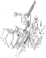
- FIG. 1 shows an exploded perspective view of an image scanning system (1)(also referred to as an "optical scanning system” or “optical scanner”) which comprises an upper housing (2) and a lower housing (3) configured to mateably engage to provide a hollow inside space (4) of sufficient volume to contain in operable relation an image sensor (5) and an image sensor driver (6).
- the upper housing (2) and the lower housing (3) in mated engagement can each provide an substantially planar external face (7)(8) disposed in substantially opposed parallel relation.
- the substantially planar external faces (7)(8) of the upper housing (2) and lower housing (3) can respectively include an upper transparent window (9) and in certain embodiments further include a lower transparent window (10), each transparent window (9)(10) having a border defined by an opaque portion (36) of the external face (7)(8) where transparency is not required.
- substantially planar for the purposes of this invention means having sufficient flatness to allow all or a portion of the scannable area (40) of an article (11) to be positioned downward upon the upper transparent window (9) or for the image scanning system (1) to be inverted and the upper transparent window (9) positioned upon all or a portion of the scannable area (40) of an upward facing article (11).
- Embodiments of the upper housing (2) and the lower housing (3) including at least the upper transparent window (9) can be fabricated, molded, or otherwise formed from a material or combination of materials such as metal, plastic, glass, or the like.
- the upper housing (2) and lower housing (3) can be provided as one piece, two pieces, or a greater number of pieces depending upon the particular embodiment of the image scanning system (1).
- the image sensor (5) and image sensor driver (6) can be operably arranged within the hollow inside space (4) defined by mateable engagement of the upper housing (2) and the lower housing (3).
- the image sensor driver (6) can include a motor (13) or other device which generates rotation in a drive wheel (14) or other element having a substantially circular perimeter.
- the circumference of the drive wheel (14) can be substantially smooth but can further provide teeth, grooves, or other elements which matingly engage a transmission means (15) circumferentially coupled about the drive wheel (14) and about a slave wheel (16) or other substantially circular element such that rotation of the drive wheel (14) generates circuitous travel of the transmission means (15) about the drive wheel (14) and the slave wheel (16).
- the transmission means (15) can comprise a belt, toothed belt, chain, cable, or the like having an external configuration which matingly engages the drive wheel (14) and the slave wheel (16) for circuitous travel.
- the image sensor (5) can be coupled to the transmission means (15) and slidely coupled on guide shaft (17) such that circuitous travel of the transmission means (15) about the drive wheel (14) and the slave wheel (16) in a first direction urges the image sensor (5) along the guide shaft (17) in a first direction (18) and circuitous travel of the transmission means (15) in the opposite direction urges the image sensor (5) along the guide shaft (17) in a second direction (19).
- the arrangement of the motor (13), drive wheel (14), slave wheel (16), transmission means (15) and guide shaft (17) have an operable relation within the inside hollow space (4) such that the image sensor (5) travels along the guide shaft (17) from a first image sensor position (12a) a sufficient distance in the first direction (18) and from a second image sensor position (12b) in the second direction (19) to scan the sensed area (25) of the upper transparent window (9). Understandably, other mechanical assemblies could be utilized to generate travel of the image sensor (5) in relation to the upper transparent window (9).
- the image sensor (5) can be maintained in fixed relation with the upper transparent window (9) and movement of the upper transparent window (9) in relation to the surface of the article (11) generates a scan of the scannable surface (40) of the article (11).
- the image sensor (5) can be a contact image sensor (CIS) (21) mounted within a supporting framework (20).
- the CIS (21) mounts within the supporting framework (20) and the supporting framework (20) slidely coupled to the guide shaft (17) locates the CIS (21) at a substantially consistent distance from the upper transparent window (9) as the image sensor (5) travels along the guide shaft (17) from the first image sensor position (12a) to the second image sensor position (12b) to scan the sensed area (25) of the upper transparent window (9).
- the CIS (21) can be in the configuration of a strip-shaped sensor element (22) having one or a linear array of detectors which can be covered by a focusing lens (23) and flanked by red, green and blue light emitting diodes ("LEDs") (24) for illumination of the sensed area (25) of the upper transparent window (9).
- One or more light blocking elements (26) direct the light (27) toward the upper transparent window (9).
- the light blocking elements (26) can comprise a pair of light blocking strips one each disposed on opposed lateral sides of the CIS (21).
- the light-blocking elements (26) can be a light blocking housing arranged around the CIS (21). Understandably, the light-blocking elements (26) can be configured in any manner which directs light (27) toward the upper transparent window (9) and blocks light (27) from the lateral sides (28)(29)(see for example Figure 7 ) of the strip-shaped sensing element (22).
- the light-sensing elements (30) of the sensor element (22) can provide a silicon surface which can be divided up into a plurality of discrete square cells, each having dimensional relations depending upon the required scanning resolution (for example a 400 dpi scanner will use a CIS whose cells are 1/400" across).
- a portion of the light (27) emitted toward the upper transparent window (9) can be directed from the surface of the article (11) onto the silicon surface.
- This type of optical system is 1:1, there is no reduction or enlargement; and this results in a scanner having the greatest resolving power and geometric accuracy.
- particular embodiments can further provide a cover (31) rotatably mounted to the upper housing (2) by a hinge element (32) between an open position (33) and closed position (31)(see for example Figure 3 ).
- a hinge element (32) In the closed position (34), the inside cover surface (35) the upper transparent window (9).
- the cover (31) can have sufficient dimensional relations to cover all or substantially the entirety of the upper transparent window (9).
- the hinge element (32) has a configuration which allows the cover (31) to be releasably attached in relation to the upper housing (2).
- the upper transparent window (9) can be disposed facing upward to scan an article (11).
- the cover (31) can be established in the open position (33) and the article (11) positioned with the scannable area (40) facing downward on the upper transparent window (9).
- the cover (31) can then be established in the closed position (34) over the article (11)(as shown in Figure 5 ).
- the scanning cycle (42) commences in which the image sensor (5) travels along the guide shaft (17) from a first image sensor position (12a) a sufficient distance for the article (11)(or a portion of the article (11)) to be illuminated by the LEDs (24) and a portion of the light (27) reflectively directed (reflected light (39)) to the CIS (21) (sensor element (22)) to generate a signal (38) which varies in relation to differences in the amount of reflected light (39) from the surface of the article (11).
- the cover (31) can be released from the upper housing (2) which allows the image scanning system (1) to be inverted allowing the sensed area (25) of the upper transparent window (9) to be disposed in downward facing engagement with the upwardly facing scannable area (40) of an article (11)(see for example Figure 13 ).
- the switch (37) can be configured to provide a first switch and a second switch one each accessible in the upward facing or downward facing condition of the upper transparent window (9).
- An alternative embodiment of the switch (37) provides a single one piece switch button (95) having a configuration which wraps sufficiently about the side of the mated upper housing (2) and lower housing (3) to dispose a portion of the switch button (95) accessible regardless as to whether the upper transparent window (9) has utilization in the upward facing condition or downward facing condition for scanning an article (11).
- certain embodiments of the invention can further include an upper transparent window having a scanned area (25) and a lower transparent window (10) which allows alignment of the scanned area (25) with the scannable area (40) of an article (11).
- a light filter can be coupled to the lower transparent window (10) to reduce or avoid stray light or from light being reflected from the lower transparent window (10) to the scanned area (25) of the upper transparent window (10) to improve or avoid reduction in quality of the image (43).
- the light filter (124) passes light incident in substantially perpendicular relation to the surface of the lower transparent window (10) but blocks light incident at about 45 degrees to the surface of the lower transparent window (10) (or incident at an angle that generates stray light or reflects light that lessens the quality of images generated).
- the material available through 3M Optical Systems Division as LCD privacy filters used in PN PF 28.0W can be utilized.
- an article (11) having a scannable area (40) greater than the sensed area (25) of the upper transparent window (9) can require serial acquisition of a plurality of scanning cycles (42) each over a portion of the scannable area (40) of the article (11).
- the plurality of scanning cycles (42) can be acquired in relation to a single dimension of the article (11) or two dimensions of the article (11).
- the upper transparent window (9) can be serially positioned linearly in one direction (vertically or horizontally) or in both directions (vertically and horizontally) between scanning cycles (42).
- image means the portion of the scannable area (40) of an article (11) transformed by the image scanning system (1) during a scanning cycle (42) into a digital representation of the scannable area (40) retrievable stored in a memory element (60) for subsequent monitor display or rendering in a tangible form.
- the term "stitched" for the purposes of this invention means computer implemented processing of the data generated by two or more scanning cycles (42) of the image scanning system (1) each one of the plurality of scanning cycles (42) having sufficient overlap with at least one other of the plurality of scanning cycles (42) to allow the overlapped data to be matched to allow the production of a single image (44) from more than one of the plurality of scanning cycles (42).
- a linear guide element can be coupled to the upper housing (2) or the lower housing (3)(or both) to reduce or avoid rotation of the sensed area (25) of the upper transparent window (9)(or rotation of the image scanning system (1)) in relation to the article (11) between serial scanning cycles (42).
- the linear guide element (45) (configured as one continuous piece or as discontinuous pieces) provides along at least one side (47) of the housing (2)(3) a linear external surface (41)(the term "linear” as used herein means a substantially straight).
- the linear external surface (41) can be engaged against a linear guiding surface (46).
- the linear guiding surface (46) can have fixed engagement in relation to a supporting surface (48) on which the article (11) can be located with the scannable area (40) upwardly facing.
- the linear guide element (45) can be located to abut the linear guiding surface (46) with the scannable area (40) of the article (11) facing upward between the upper transparent window (9) and the supporting surface (48). A portion of the scannable area (40) can be viewed through the lower transparent window (10).
- the linear guide element (45) of the image scanning system (1) can be serially repositioned against or slidely positioned along the linear guiding surface (46) to position portions of the scannable area (40) of the article (11) in relation to the upper transparent window (9) to reduce or avoid rotation of sensed area (25) of the upper transparent window (9) in relation to the article (11).
- the upper transparent window (9) can further include viewable indicator marks (49) which define the bounds of the sensed area (25) of the upper transparent window (9).
- the portion of the scannable area (40) of the article (11) disposed inside the sensed area (25) of the upper transparent window (9) within the bounds defined by the indicator marks (49) will be sensed by the CIS (21).
- the portion of the scannable area (40) of the article (11) disposed outside of the sensed area (25) of the upper transparent window (9) having bounds defined by the indicator marks (49) will not be sensed by the CIS (21).
- the viewable indicator marks (49) can be viewed through the lower transparent window (10), such that the upper transparent window (9) can in the downwardly facing condition be positioned on scannable area (40) of the article (11) such that the desired portion of the scannable area (40) occurs within the sensed area (41) of the upper transparent window (9).
- the lower transparent window (10) can further include viewable overlap indicators (50) which define the portion of the sensed area (25) of the upper transparent window (9) to overlap between each of a plurality of scanning cycles (42) to allow stitched assembly of the corresponding plurality of images (43) into a single image (44).
- the viewable overlap indicators (50) can indicate the amount of overlap of the sensed area (25) between any two of a plurality scanning cycles (42) to allow stitched horizontal assembly of the corresponding plurality of images (43).
- the viewable overlap indicators (50) can indicate the amount of overlap of the scanned area (41) between any two scanning cycles (42) to allow stitched vertical assembly of the corresponding plurality of images (43)(or allow both stitched vertical and horizontal assembly) into a single image (44).
- viewable overlap indicators (50) can comprise a pair of viewable vertical lines (51) viewable in the lower transparent window (10) disposed in substantially vertical parallel opposed relation a distance apart.
- a first viewable vertical line (52a) can be positioned in relation to a location in the scannable area (40) of the article (11) and a first of a plurality of scanning cycles (42) achieved.
- the image scanning system (1) can be repositioned horizontally on the scannable area (40) of the article (11).
- a second viewable vertical line (52b) can be positioned at the same location as the first vertical line (51a) was positioned for the preceding first of the plurality of scanning cycles (42) and a second of the plurality of scanning cycles (42) can be achieved.
- sufficient horizontal overlap of the scannable area (40) of article (11)(or sensed area (25) of the upper transparent window (9)) between the first and second of a plurality of scanning cycles (42) can be achieved to allow stitching of the correspondingly generated plurality of images (43) of the scannable area (40) into a single image (44).
- a first viewable horizontal line (54a) can be positioned in relation to a location in the scannable area (40) of the article (11) and a first of a plurality of scanning cycles (42) achieved.
- the image scanning system (1) can be repositioned vertically on the scannable area (40) of the article (11).
- a second viewable vertical line (54b) can be positioned at the same location as the first vertical line (54a) was positioned for the preceding first of the plurality of scanning cycles (42) and a second of the plurality of scanning cycles (42) can be acheived.
- the display screen (56) can be a liquid crystal device ("LCD”) or other display device suitable for display of graphic images, alphanumeric characters, symbols, or the like recognizable to the user.
- a scanner control interface (57) can provide two-dimensional movement of a visible symbol (pointer) on the display screen (56) which allows the user to control the functionalities of the image scanner system (1), as further described below.
- Many implementations of the scanner control interface (57) are known in the art including a trackball, mouse, joystick or keys capable of signaling movement of a given direction or manner of displacement.
- the scanner control interface (57) can be utilized to access and utilize the functionalities of an operating system program (61) of an internal computer (58).
- the image scanning system (1) can further include an internal computer (58) which can use a non-volatile main memory (60) in lieu of random access memory.
- the non-volatile main memory (60) stores an operating system program (61) and an application program (62).
- the operating system program (61) and the application program (62) used by the internal computer (58) can be retained in an initialized and executable state within the non-volatile main memory (60) when the internal computer (58) of the scanning system (1) is powered off.
- the operating system software (61) and application program (62) can be used by the image scanning system (1) during boot up and while operating after boot up.
- the non-volatile main memory (60) can be read from and written to.
- non-volatile main memory 60
- non-volatile main memory 60
- the non-volatile main memory (60) can be used in the image scanning system (1) to provide a processor (63) and CPU registers (64).
- FeRAM ferrromagnetic or ferroelectronic RAM
- flash memory or various other types of non-volatile memory can be used for the non-volatile main memory (60), cache memory (65) or CPU registers (64).
- the internal computer (58) can further include a memory card reader (66) for reading from or writing to a removable memory card (67); however, the invention is not so limited and in the alternative the internal computer (58) can include one or more of a magnetic disk drive for reading from or writing to a removable magnetic disk, and an optical disk drive for reading from or writing to a removable optical disk such as a CD ROM or other optical media, a flash drive reader for reading from or writing to a removable flash drive, or the like.
- a magnetic disk drive for reading from or writing to a removable magnetic disk
- an optical disk drive for reading from or writing to a removable optical disk such as a CD ROM or other optical media
- a flash drive reader for reading from or writing to a removable flash drive, or the like.
- the processor (63) interacts with either or both non-volatile main memory (60) and non-volatile cache memory (65), as well as with CPU registers (64).
- the controlling logic executed by processor (63) enables the processor (63) to read from and write to the non-volatile main memory (60) or other non-volatile memory.
- the application program (62) is read from non-volatile main memory (60) and executed. Information generated during normal operation of the image scanning system (1) can be written to the non-volatile main memory (60).
- the internal computer (58) implemented functionalities of the image scanning system (1) shown in Figure 1 as functional block components are more fully described below as optional selections or various processing steps. It should be appreciated that such functional blocks may be realized by any number of hardware or software components configured to perform the specified functions.
- the present invention may employ various integrated circuit components which function without limitation as memory elements, processing elements, logic elements, look-up tables, or the like, which may carry out a variety of functions under the control of the processor (63) or other control devices.
- the software elements of the present invention may be implemented with any programming or scripting language such as C, C++, Java, COBOL, assembler, PERL, Labview, or any graphical user interface programming language, extensible markup language (XML), Microsoft's Visual Studio .NET, Visual Basic, or the like, with the various algorithms or Boolean Logic being implemented with any combination of data structures, objects, processes, routines or other programming elements.
- programming or scripting language such as C, C++, Java, COBOL, assembler, PERL, Labview, or any graphical user interface programming language, extensible markup language (XML), Microsoft's Visual Studio .NET, Visual Basic, or the like
- XML extensible markup language
- Microsoft's Visual Studio .NET Visual Basic
- the present invention might employ any number of conventional techniques for data transmission, signaling, data processing, network control, and the like.
- the internal computer (58) implemented functions of the application program (62) can provide a power management module (68) which functions to adjust power consumption of the image scanning system (1) depending upon operational status and can for example switch between a scanning mode (69) when transmitting a signal (38) during scanning of an article (11), a receive mode (70) for receiving data packets or signal transmission, an idle mode (71) when the scanner system is neither scanning or receiving packets or signal transmission, and a sleep mode (72) in which scanning and signal transmission and receiving packets cannot occur and the scanner system (1) must be woken to the idle mode (71) by explicit instruction.
- a scanning mode 69
- a receive mode 70
- an idle mode (71) when the scanner system is neither scanning or receiving packets or signal transmission
- a sleep mode (72) in which scanning and signal transmission and receiving packets cannot occur and the scanner system (1) must be woken to the idle mode (71) by explicit instruction.
- the software program (62) can further provide a signal translation module (73) which functions to translate signals (38) received from the image sensor (5) into an image (44) or a plurality of images (43) representing variation in the amount of light (27) reflected by portions of the scanned area (41) of an article (11).
- the signal translation module (73) can further operate to display the image (44) on the display screen (56) as the signal (38) is translated during scanning.
- the signal translation module (73) can further function to store image(s) (43)(44) generated into the non-volatile main memory (60).
- the application program (62) can further provide an image review module (74) which functions to allow retrieval and serial viewing of image(s) (43)(44) stored into the non-volatile main memory (60).
- the application program (62) can further provide a zoom module (75) which functions to enlarge or reduce the angle of view of all or a portion of the image (44) within the display screen (56) and can further provide a pan function (76) which allows repositionable view of an area of the scanned image (43) within the display screen (56).
- the application program (62) can further provide an image resolution selection module (77) which functions to adjust image resolution in relation to a particular zoom level.
- the software application can further provide an image enhancement module (78) which allows adjustment of color, brightness, sharpness, contrast, image size, noise and crop and removal of unwanted elements, or the like.
- image enhancement module (78) which allows adjustment of color, brightness, sharpness, contrast, image size, noise and crop and removal of unwanted elements, or the like.
- the application program (62) can further provide a data embedding module (125) which can function to embed metadata into the scanned image (44).
- metadata broadly encompasses data which is made a part of an image (44) used to describe the definition, structure, and administration of the image (44) with all contents in context to facilitate subsequent use of the image (44).
- the data embedded in the image (44) as non-limiting examples can specify the tools used to create the image (44), how large the image is, the color depth, the image resolution, exposure data, when the image was created as to date and time, demographic data, distribution data, who owns the image, copyright information, contact information, image content information, metatags, geographic, geological information, global positioning system data, or the like and can include entire data files such as portable document format (PDF) files, digital audio encoding format such as MP3 files, video files, audio files, Word files, Xcel file format files, encryption, and security information or data and instructions to retrieve data files from a memory element, or remote computer whether in a LAN or WAN setting, or instructions relating to the display of image in relation to retrieval, indexing, sorting, identification, and playback of embedded or retrieved data files, or like.
- PDF portable document format
- digital audio encoding format such as MP3 files
- video files video files
- audio files Word files
- Xcel file format files encryption, and security information or data and
- the application program (62) can further provide a date-time module (79) which can function to provide date and time information related to an image (43) and by operation of the data embedding module (125) can be coupled or embedded as metadata in the image (43) and stored to the non-volatile main memory (60) whether the date and time is entered using the control device (57) or automatically generated and embedded by operation of the application program (62).
- a date-time module (79) can function to provide date and time information related to an image (43) and by operation of the data embedding module (125) can be coupled or embedded as metadata in the image (43) and stored to the non-volatile main memory (60) whether the date and time is entered using the control device (57) or automatically generated and embedded by operation of the application program (62).
- the application program (62) can further include an audio record and playback function (80) which allows sound (such as voice, music, background sound, mp3 encoded format, or the like) by use of sound input elements (81a) to be recorded and coupled or embedded to one or more images (43) for later playback on retrieval of the image (44) through sound output elements (81) typically coupled to the upper housing (9) of the scanner system (1).
- Associated sound output controls (82) can be operated by use of the scanner control interface (57).
- While the portable scanner system can be operated and can be fully independent of any other computer, certain functions can be operated in the networked environment using logical connections (85) to one or more external computers (83). These logical connections (85) are achieved by a communication device (84) coupled to the internal computer (58) above described.
- the logical connections (85) depicted in Figure 1 can include a local-area network (“LAN”) (86) or a wide-area network (“WAN”)(87).
- LAN local-area network
- WAN wide-area network
- Embodiments of the scanner system (1) used in a LAN (86) networking environment can be connected through a network interface (89) or adapter.
- Embodiments of the image scanning system (1) used in a WAN (87) networking environment can further include a modem (90) or any other type of communications device for establishing communications over the WAN (87), such as the Internet.
- the modem (90) which may be internal or external to internal computer (58) via a serial port interface (91).
- the image scanning system (1) can further include wireless interfaces (92) such as WiFi or cell phone interfaces.
- Scanned images (43) can be retrieved from storage in the non-volatile main memory (60) and can be uploaded individually or in batches to a website or FTP server for easy download to external computers (83). Conversely, image(s) (43)(44) can be downloaded from other websites and stored in the non-volatile main memory (60) of the internal computer (58).
- a particular non-limiting embodiment of the image scanning system (1) functions upon insertion of a memory card (67) or flash drive (93) to launch a website (94) constructed for the particular image scanning system (1).
- the application program (62) can further provide a geographical position system (“GPS") module (126) which functions to identify location of the scanner system (1).
- GPS geographical position system
- the location data can be embedded with date-time information generated by the date-time module (79) of the image scanning system (1).
- certain embodiments of the image scanning system (1) can include an upper housing (2) having an upper transparent window (9) and a lower housing (3) having a lower transparent window (10) which matingly engages the upper housing (3) to define a hollow inside space (4) and a pass-through aperture (116) which provides a passage (117) between substantially planar external faces (7)(8) of the upper housing (2) and the lower housing (3).
- a control interface housing (118) can have an external configuration which can be rotatably mounted within the passage (117) defined by the pass-through aperture (116).
- the pass-through aperture can have a generally rectangular configuration and the control interface housing (118) can have a generally rectangular configuration of sufficiently lesser dimensional relations to allow the control interface housing (118) to rotate within the passage (117) about pivot elements (119)(120) on the longitudinal axis (121) of the control interface housing (118).
- the control interface housing (118) locates within the internal computer (58) and the memory card reader (66) which operates as above described to control the functionalities of the image scanning system (1), as above-described; the display screen (56); and the scanner control interface (57) which provides user interface control elements (122).
- Rotation of the scanner control interface housing (118) within the pass-through aperture (116) allows the user interface control elements (122) to be disposed at either one of the substantially planar external faces (7)(8) of the upper housing (2) or the lower housing (3) which allows use of the user interface control elements (122) to control the function of the image scanning system (1) and allows viewing of the display screen (56) in either the upward facing condition or downward facing condition, as above-described.
- Figures 10 and 11 provides a cross section view showing the image sensor (5) which is driven, as above described, in a first direction (18) from a first image sensor position (12a) toward a second image sensor position (12b) to scan the scannable area (40) of an article (11) for generation of an image (44).
- the image sensor (5) can then be driven in a second direction (19) from the second image sensor position (12b) toward the first image sensor position (12a).
- the image sensor (5) including the strip shaped sensor element (22) and the light emitting diodes (24) receives power and transmits signals (38) through a flexible electrically conductive ribbon (96)(also referred to as the "conductive ribbon") having a first end (97) electrically coupled to a power source (98) and the internal computer (58) and a second end (99) electrically coupled to the image sensor (5).
- the conductive ribbon (96) can take the form of an electrically conductive wire(s) disposed on a flexible electrically insulating substrate.
- a conductive ribbon or ribbon cable suitable for use is available from Digi-Key Corporation, Part No. PS-1636; however, the invention is not so limited and a numerous and wide variety of flexible ribbon cables can be used or modified for use with embodiments of the invention, as further described below.
- the conductive ribbon (96) generally lies against the internal surface (100) of the lower housing (3), passes under the image sensor (5), and provides a loop element (101) proximate the second end (99).
- the loop element formed proximate the second end (99) allows the second end (99) to be presented to the image sensor (5) inwardly from the internal surface (100) of the side wall (105) of the joined upper housing (2) and lower housing (3) (as shown for example in Figure 11 ).
- a first portion (103)(see Figure 10 (broken line)) of conductive ribbon (96) can be drawn over a second portion (104) of the conductive ribbon (96) which lies against the internal surface (100) of the lower housing (3) to locate the loop (101) at a location at about the midpoint between the first image sensor position (12a) and the second image sensor location (12b)(as shown in Figure 10 (broken line)).
- the upper housing (2) and the lower housing (3) can have a configuration which provides sufficient hollow inside space (4) between the internal surface (100) of the side wall (105) of the joined upper housing (2) and lower housing (3) and the first image sensor side (102) to accommodate the loop (101) of the flexible conductive strip (96) when the image sensor (5) locates at the second image sensor position (12b).
- an article (11) may be connected or otherwise coupled to an object (107) in fixed relation.
- the object (107) may prevent alignment of the sensed area (25) of the upper transparent window (9) of the image scanning system (1) with all or a portion of the scannable area (4) the article (11).
- the article (11) to be scanned may be a page (108) of a book (109).
- the object (107) may be the spine (110) of the book (109) to which the page (108) is bound proximate an edge (111).
- the side wall (105) of image scanning system (1) can be forcibly urged against the spine (110) of the book (109) but may not be positionally fixed over the spine (110) of the book (109).
- the margin (106) between the spine (110) and the imprinted area (123) of the page (108) may not be sufficient to allow alignment of the sensed area (25) of the upper transparent window (9) and the imprinted area (123). Because the margin (106) cannot be increased and because the side wall (105) configuration of the upper housing (2) and the lower housing (3)(for example as shown in Figures 10 and 11 ) cannot be readily altered, it may not be possible to positionally fix the upper transparent window (9) in relation to the article (11) to obtain a complete image (44) of the imprinted area (123) on the page (108).
- This example is intended to be illustrative and not limiting with respect to the types of objects (107) and articles (11) which may have a fixed relation which prevents certain configurations of the image scanning system (1) from being positionally fixed in relation with the article (11) for alignment of the scannable area (40) of the article (11) with the sensed area (25) of the upper transparent window (9).
- the image scanning system (1) can be configured to allow an article (11) to be scanned, as above-described, even when the article (11) has a margin (106) which affords limited open space in which to positionally fix the image scanning system (1) to align the scanned area (41) of the upper transparent window (9) with the scannable area (40) of the article (11).
- the upper housing (2) and lower housing (3) can be configured to provide side wall (105) having an external configuration which provides a generally flat surface (112) in substantially perpendicular relation to the substantially planar external faces (7)(8) of the upper housing (2) and the lower housing (3).
- the upper housing (2) and lower housing (3) can further provide an internal surface (100) of the side wall (105) configured with a substantially flat surface disposed in generally perpendicular relation to the substantially planar external faces (7)(8) of the upper housing (2) and the lower housing (3).
- the side wall (105) can have a thickness between the external surface and the internal surface (100) sufficient to support the upper transparent window (9), which substantially eliminates any opaque portion (36) of the substantially planar external faces (7)(8), except for the thickness of that portion of the side wall (105) which supports the upper transparent window (9).
- the thickness of the sidewall (105) can be about one-quarter of an inch and the upper transparent window can engage about the inner one-half the thickness of the side wall (105).
- the side wall (105) configured as above-described allows the image sensor (5) at the second image sensor position (12b) to be disposed at a location of lesser distance from the internal side wall surface (100) and the external surface of the side wall (105) as compared to other embodiments of the configuration shown in Figures 10 and 11 . Understandably, the internal surface (100) sidewall (105) can be configured to provide the least or lesser distance between the sensor element (22) of the image sensor (5) and the external surface (36) of the side wall (105).
- the sensed area (25) of the upper transparent window (9) can be positionally fixed at a lesser distance from an object (107) when engaged with the external surface of the image scanner (1).
- the distance at which the sensed area (25) of the upper transparent window (9) can located relative to the external surface of the side wall (105) of the image scanning system (1) can be substantially less for the embodiment shown in Figure 12 as compared to the embodiment of Figure 11 .
- embodiments of the invention which have a configuration of the side wall (105) which locate the image sensor (5) proximate the internal surface (100) of the side wall (105) may preclude or makes less practical formation of the loop (101) and electrical coupling of the second end (99) of the conductive ribbon (96) from the first image sensor side (102) which faces the internal surface (100).
- the conductive ribbon (96) can be alternately configured to electrically couple the second end (99) to image sensor (5) from the second image sensor side (113) facing away from the internal surface (100) of the side wall (105).
- the first end (97) electrically coupled to a power source (98) and internal computer (58).
- the conductive ribbon (96) between the first end (97) and the occurrence of a fold element (114) can have one side disposed against the internal surface (100) of the lower housing (3).
- the fold element (114) can have a substantially fixed configuration formed in the substrate material on which the conductive element is disposed. As to those substrates which comprise a plastic layer or film the fold element (114) can be generated by application of heat to the substrate sufficient to allow the fold to be generated and then allowing the plastic to cool or cure.
- the second end (99) of the conductive ribbon (96) can be electrically coupled to the image sensor (5) from the second image sensor side (113) as shown in Figure 10 .
- the fold element (114) functions to provide a first portion (103) of the conductive ribbon (96) which can be disposed in a folded back condition (115) in which the first portion (103) of the conductive ribbon (96) releasably engages the second portion (104) of the conductive ribbon (96).
- the image sensor (5) travels from the first image sensor position (12a) toward the second image sensor position (12b)
- the first portion (103) of the conductive ribbon (96) pays out (as shown in Figure 10 ) from the folded back condition (115).
- the first portion (103) of the conductive ribbon (96) returns to the folded back condition (115) in which the first portion (103) has layered engagement with the second portion (104) of the conductive ribbon (96).
- This configuration of the conductive ribbon (96) obviates use of the loop element (101) and electrical coupling of the second end (99) of the conductive ribbon (96) from the first image sensor side (102) as shown in Figures 10 and 11 .
- FIG. 12 shows that the second portion (104) of the conductive ribbon (96) has a surface that lies against the internal surface (100) of the lower housing (3); the invention is not so limited, and the conductive ribbon (96) having a fold element (114) can be operably located in the inside space (4) in any manner which allows the first portion (103) to pay out from and return to the fold back condition (115) as the image sensor (5) travels between first images sensor position (12a) and the second image sensor position (12b).
Landscapes
- Engineering & Computer Science (AREA)
- Multimedia (AREA)
- Signal Processing (AREA)
- Facsimile Scanning Arrangements (AREA)
- Image Input (AREA)
Claims (15)
- Optischer Scanner, umfassend:a) ein oberes Gehäuse (2) mit einem oberen transparenten Fenster (9);b) ein unteres Gehäuse (3), das anpasst in das obere Gehäuse eingreift, um einen hohlen Innenraum (4) zu definieren;c) einem Bildsensor (5) und einem Bildsensor-Treiber (6), die funktionsfähig innerhalb des hohlen Innenraumes angeordnet sind, wobei der Bildsensor zwischen einer ersten Bildsensor-Position (12a) und einer zweiten Bildsensor-Position (12b) angesteuert wird; undd) einem flexiblen elektrisch-leitfähigen Band (96) mit einer Länge, die zwischen einem ersten Ende (97), das mit einer Stromquelle (98) verbunden ist, und einem zweiten Ende (99), das mit dem Bildsensor verbunden ist, angeordnet ist, wobei das flexible elektrisch-leitfähige Band eine Konfiguration aufweist, die es dem Bildsensor (5) ermöglicht, sich zwischen einer ersten Bildsensor-Position (12a) und einer zweiten Bildsensor-Position (12b) zu bewegen, wobei die Konfiguration ein Faltelement (114) beinhaltet, das in dem flexiblen elektrisch-leitfähigen Band an einer Stelle zwischen dem ersten Ende und dem zweiten Ende auftritt, um einen ersten Abschnitt (103) und einen zweiten Abschnitt (104) des flexiblen elektrisch-leitfähigen Bandes (96) zu definieren, dadurch gekennzeichnet, dass das Faltelement (114) den ersten Abschnitt (103) des flexiblen elektrisch-leitfähigen Bandes (96) in einem umgefalteten Zustand in Bezug auf den zweiten Abschnitt (104) in der ersten Bildsensor-Position (12a) anordnet, wobei der erste Abschnitt (103) des flexiblen elektrisch-leitfähigen Bandes (96) aus dem umgefalteten Zustand austritt, wenn sich der Bildsensor (5) in Richtung der zweiten Bildsensor-Position (12b) bewegt.
- Optischer Scanner nach Anspruch 1, wobei
das obere Gehäuse (2) und das untere Gehäuse (3) im angepassten Eingriff eine Seitenwand (105) mit einer Dicke bereitstellen, die zwischen einem Paar von im Allgemeinen flachen Oberflächen mit im Wesentlichen senkrechter fester Beziehung zu einer im Wesentlichen planaren Außenfläche des oberen Gehäuses (2) und des unteren Gehäuses (3) angeordnet ist;
und wobei die zweite Bildsensor-Position (12b) den Bildsensor (5) im Wesentlichen angrenzend an eine Innenfläche (I00) der Seitenwand positioniert, die dazu dient, den Abstand zwischen der Außenfläche (36) der Seitenwand und dem Rand eines gescannten Bereichs des oberen transparenten Fensters (9) zu verringern. - Optischer Scanner nach Anspruch 2, wobei das untere Gehäuse (3) ein unteres transparentes Fenster (10) aufweist, wobei das obere transparente Fenster (9) durch das untere transparente Fenster sichtbar ist.
- Optischer Scanner nach Anspruch 3, ferner umfassend sichtbare Indikator-Markierungen (49), die in dem unteren transparenten Fenster (9) angeordnet sind und den Rand des gescannten Bereichs des oberen transparenten Fensters (I0) anzeigen.
- Optischer Scanner nach Anspruch 4, ferner umfassendsichtbare Überlappungsindikatoren (50), die in dem unteren transparenten Fenster (9) angeordnet sind und die eine Überlappung zwischen einer Vielzahl von Scan-Zyklen anzeigen, um eine verknüpfte Anordnung einer entsprechenden Vielzahl von Bildern in einem Bild zu ermöglichen.
- Optischer Scanner nach Anspruch 5, wobei die sichtbaren Überlappungsindikatoren (50) eine ausreichende horizontale Überlappung des gescannten Bereichs zwischen den Scan-Zyklen bereitstellen, um eine verknüpfte, horizontale Anordnung der entsprechenden Vielzahl von Bildern in einem Bild zu ermöglichen.
- Optischer Scanner nach Anspruch 6, wobei die sichtbaren Überlappungsindikatoren (50) eine ausreichende vertikale Überlappung des gescannten Bereichs zwischen den Scan-Zyklen bereitstellen, um eine verknüpfte, vertikale Anordnung der entsprechenden Vielzahl von Bildern in einem Bild zu ermöglichen.
- Optischer Scanner nach Anspruch 1, des Weiteren mit einer Durchgangsöffnung (116), die einen Durchgang zwischen im Wesentlichen planaren Außenflächen des oberen Gehäuses (2) und des unteren Gehäuses (3) bereitstellt, und einem Steuerschnittstellengehäuse (118) mit einer äußeren Konfiguration, das innerhalb des durch die Durchgangsöffnung definierten Durchgangs drehbar gelagert werden kann.
- Optischer Scanner nach Anspruch 1, wobei das obere Gehäuse (2) und das untere Gehäuse (3) konfiguriert sind, um eine Seitenwand (105) mit einer äußeren Konfiguration bereitzustellen, die eine im Allgemeinen flache Oberfläche in im Wesentlichen senkrechter Beziehung zu den im Wesentlichen planare Außenflächen des oberen Gehäuses und des unteren Gehäuses bereitstellt.
- Optische Scanner nach Anspruch 1, ferner umfassend einen reduzierten Rand (106) angeordnet zwischen der Außenfläche mindestens einer Kante, des oberen Gehäuses (2) und des unteren Gehäuses (3) im angepassten Eingriff, und dem Rand eines gescannten Bereichs des oberen transparenten Fensters (9), wobei der reduzierte Rand des oberen Gehäuses und des unteren Gehäuses im angepassten Eingriff eine Konfiguration aufweist, die eine entsprechende Innenfläche des oberen Gehäuses und des unteren Gehäuses im angepassten Eingriff benachbart zu dem Bildsensor (5) in einer zweiten Bildsensor-Position positioniert.
- Optischer Scanner nach Anspruch 10, wobei der reduzierte Rand (106) des oberen Gehäuses und des unteren Gehäuses im angepassten Eingriff den Bildsensor (5) in der zweiten Bildsensorposition (12b) in einem Abstand von der Innenfläche des oberen Gehäuses und des unteren Gehäuses im angepassten Eingriff in einem Abstand in einem Bereich von etwa einem sechzehntel Zoll und etwa einem halben Zoll positioniert.
- Optischer Scanner nach Anspruch 2, ferner umfassendein lineares Kantenführungselement (45), entlang mindestens einer Seite des oberen Gehäuses (2) und des unteren Gehäuses (3) in angepasstem Eingriff, das beschaffen ist für einen gleitenden Eingriff mit einer im Allgemeinen linearen Führungsfläche, um die Drehung des gescannten Bereichs des oberen transparenten Fensters (9) zwischen der Vielzahl von Scan-Zyklen zu reduzieren oder zu vermeiden.
- Optischer Scanner nach Anspruch 2, ferner umfassendeinen Lichtfilter (124), der mit der Außenfläche des unteren transparenten Fensters (10) gekoppelt ist, der einfallendes Licht im Wesentlichen senkrecht zu dem unteren transparenten Fenster überträgt, und wobei der Lichtfilter (124) Licht auf das untere transparente Fenster blockiert, das in einem Winkel zwischen etwa 35 Grad und 55 Grad einfällt.
- Optischer Scanner nach Anspruch 2, wobei die Seitenwand (105) des oberen Gehäuses und des unteren Gehäuses im angepassten Eingriff eine Dicke zwischen etwa einem achtel Zoll und etwa einem halben Zoll aufweist.
- Optischer Scanner nach Anspruch 14, wobei das obere transparente Fenster (9) und das untere transparente Fenster (10) etwa die Hälfte der Dicke der Seitenwand erfassen.
Applications Claiming Priority (5)
| Application Number | Priority Date | Filing Date | Title |
|---|---|---|---|
| US25702109P | 2009-11-01 | 2009-11-01 | |
| US25707009P | 2009-11-02 | 2009-11-02 | |
| US39661110P | 2010-05-28 | 2010-05-28 | |
| US40312610P | 2010-09-10 | 2010-09-10 | |
| PCT/US2010/002862 WO2011053356A2 (en) | 2009-11-01 | 2010-10-30 | Mobile optical scanning system |
Publications (3)
| Publication Number | Publication Date |
|---|---|
| EP2494773A2 EP2494773A2 (de) | 2012-09-05 |
| EP2494773A4 EP2494773A4 (de) | 2014-11-26 |
| EP2494773B1 true EP2494773B1 (de) | 2018-12-12 |
Family
ID=43922942
Family Applications (1)
| Application Number | Title | Priority Date | Filing Date |
|---|---|---|---|
| EP10827277.4A Active EP2494773B1 (de) | 2009-11-01 | 2010-10-30 | Mobiles optisches erfassungssystem |
Country Status (4)
| Country | Link |
|---|---|
| US (1) | US9025220B2 (de) |
| EP (1) | EP2494773B1 (de) |
| AU (1) | AU2010313758B2 (de) |
| WO (1) | WO2011053356A2 (de) |
Families Citing this family (7)
| Publication number | Priority date | Publication date | Assignee | Title |
|---|---|---|---|---|
| US8559063B1 (en) | 2012-11-30 | 2013-10-15 | Atiz Innovation Co., Ltd. | Document scanning and visualization system using a mobile device |
| TWD166688S (zh) * | 2014-03-10 | 2015-03-21 | 虹光精密工業股份有限公司 | 掃描器 |
| US20200274986A1 (en) * | 2016-04-27 | 2020-08-27 | Hewlett-Packard Development Company, L.P. | Scan assembly frame |
| CN106778900A (zh) * | 2016-12-30 | 2017-05-31 | 天津诗讯科技有限公司 | 一种图形动态关系识别设备 |
| US10970578B2 (en) * | 2019-02-07 | 2021-04-06 | Johnson Controls Fire Protection LP | System and method for extracting information from a non-planar surface |
| US12013585B2 (en) * | 2021-01-26 | 2024-06-18 | Apple Inc. | Electronic devices with optical fiber ribbons |
| US11394851B1 (en) * | 2021-03-05 | 2022-07-19 | Toshiba Tec Kabushiki Kaisha | Information processing apparatus and display method |
Family Cites Families (8)
| Publication number | Priority date | Publication date | Assignee | Title |
|---|---|---|---|---|
| AUPO884297A0 (en) | 1997-08-27 | 1997-09-18 | Orme, Gregory Michael | Imaging devices |
| US6101004A (en) | 1998-01-30 | 2000-08-08 | Sung; Hsiung-Wei | Scanning device |
| US7683926B2 (en) | 1999-02-25 | 2010-03-23 | Visionsense Ltd. | Optical device |
| US6587231B1 (en) | 1999-11-05 | 2003-07-01 | Teco Image Systems Co., Ltd. | Scanning apparatus |
| US6651886B2 (en) | 2001-04-13 | 2003-11-25 | Symbol Technologies, Inc. | Optical code readers with holographic optical elements |
| TW530481B (en) | 2001-10-19 | 2003-05-01 | Primax Electronics Ltd | Anti-abrasion flat flexible cable structure |
| JP4035340B2 (ja) | 2002-02-07 | 2008-01-23 | キヤノン株式会社 | 画像読取装置 |
| US7095532B2 (en) * | 2002-10-03 | 2006-08-22 | Yu-Shan Chang | Scanning apparatus |
-
2010
- 2010-10-29 US US12/925,802 patent/US9025220B2/en active Active
- 2010-10-30 EP EP10827277.4A patent/EP2494773B1/de active Active
- 2010-10-30 AU AU2010313758A patent/AU2010313758B2/en active Active
- 2010-10-30 WO PCT/US2010/002862 patent/WO2011053356A2/en not_active Ceased
Non-Patent Citations (1)
| Title |
|---|
| None * |
Also Published As
| Publication number | Publication date |
|---|---|
| US9025220B2 (en) | 2015-05-05 |
| EP2494773A4 (de) | 2014-11-26 |
| WO2011053356A3 (en) | 2011-11-03 |
| AU2010313758B2 (en) | 2016-01-28 |
| WO2011053356A8 (en) | 2011-12-29 |
| EP2494773A2 (de) | 2012-09-05 |
| AU2010313758A1 (en) | 2012-06-14 |
| WO2011053356A2 (en) | 2011-05-05 |
| US20110102861A1 (en) | 2011-05-05 |
Similar Documents
| Publication | Publication Date | Title |
|---|---|---|
| EP2494773B1 (de) | Mobiles optisches erfassungssystem | |
| JP4870815B2 (ja) | 被写体上に内在する不可視イメージを観測しながら簡易に撮影ができる装置、および、それを利用する方法 | |
| EP2531954B1 (de) | Vorrichtung und verfahren zur erfassung eines objekts auf einer arbeitsfläche | |
| TW201214291A (en) | Mobile phone assembly with microscope capability | |
| US20130026223A1 (en) | Selecting images using machine-readable codes | |
| US20140098392A1 (en) | Photo editor in a multifunction printer | |
| US8596523B2 (en) | Index print with machine-readable codes | |
| US8967482B2 (en) | Image selection method using machine-readable codes | |
| US20090166537A1 (en) | Light receiving apparatus, electronic apparatus and image display apparatus | |
| CN101069188A (zh) | 用户可编程的交互式显示设备和方法 | |
| CN101783860A (zh) | 扫描装置及其扫描装订文件的方法 | |
| US20050083556A1 (en) | Image cropping based on imaged cropping markers | |
| Lanman | Mask-based light field capture and display | |
| JP3144146U (ja) | バーコード読取対応携帯電話 | |
| Vannier et al. | Introduction to 3D imaging | |
| Catanzariti et al. | Forests and pyramids: Using image hierarchies to understand landsat images | |
| JP4182019B2 (ja) | 画像読取装置 | |
| Hemmy | Future directions in three-dimensional imaging | |
| Sarvas et al. | The Digital Path (ca. 1990–) | |
| US20060092456A1 (en) | Recording medium storing print ordering file, method and apparatus for creating print ordering file | |
| Tinsley | Secretary Emeritus Ripley and Wife, Mary Livingston Ripley | |
| Watson | Teach Yourself Visually IPhoto'09 | |
| Sherman | The Complete Idiot's Guide to Canon EOS Digital Cameras | |
| JPH01150974A (ja) | 画像情報の記録・検索装置 | |
| Lynch | Mpala and Ol Jogi Slides, 1996 |
Legal Events
| Date | Code | Title | Description |
|---|---|---|---|
| PUAI | Public reference made under article 153(3) epc to a published international application that has entered the european phase |
Free format text: ORIGINAL CODE: 0009012 |
|
| 17P | Request for examination filed |
Effective date: 20120601 |
|
| AK | Designated contracting states |
Kind code of ref document: A2 Designated state(s): AL AT BE BG CH CY CZ DE DK EE ES FI FR GB GR HR HU IE IS IT LI LT LU LV MC MK MT NL NO PL PT RO RS SE SI SK SM TR |
|
| DAX | Request for extension of the european patent (deleted) | ||
| RAP1 | Party data changed (applicant data changed or rights of an application transferred) |
Owner name: TECO IMAGE SYSTEM CO., LTD. |
|
| RAP1 | Party data changed (applicant data changed or rights of an application transferred) |
Owner name: TECO IMAGE SYSTEMS CO., LTD. |
|
| A4 | Supplementary search report drawn up and despatched |
Effective date: 20141029 |
|
| RIC1 | Information provided on ipc code assigned before grant |
Ipc: H04N 1/00 20060101AFI20141023BHEP |
|
| RAP1 | Party data changed (applicant data changed or rights of an application transferred) |
Owner name: TECO IMAGE SYSTEMS CO., LTD. |
|
| GRAP | Despatch of communication of intention to grant a patent |
Free format text: ORIGINAL CODE: EPIDOSNIGR1 |
|
| STAA | Information on the status of an ep patent application or granted ep patent |
Free format text: STATUS: GRANT OF PATENT IS INTENDED |
|
| INTG | Intention to grant announced |
Effective date: 20180712 |
|
| GRAS | Grant fee paid |
Free format text: ORIGINAL CODE: EPIDOSNIGR3 |
|
| GRAA | (expected) grant |
Free format text: ORIGINAL CODE: 0009210 |
|
| STAA | Information on the status of an ep patent application or granted ep patent |
Free format text: STATUS: THE PATENT HAS BEEN GRANTED |
|
| AK | Designated contracting states |
Kind code of ref document: B1 Designated state(s): AL AT BE BG CH CY CZ DE DK EE ES FI FR GB GR HR HU IE IS IT LI LT LU LV MC MK MT NL NO PL PT RO RS SE SI SK SM TR |
|
| REG | Reference to a national code |
Ref country code: GB Ref legal event code: FG4D |
|
| REG | Reference to a national code |
Ref country code: CH Ref legal event code: EP |
|
| REG | Reference to a national code |
Ref country code: AT Ref legal event code: REF Ref document number: 1077523 Country of ref document: AT Kind code of ref document: T Effective date: 20181215 |
|
| REG | Reference to a national code |
Ref country code: DE Ref legal event code: R096 Ref document number: 602010055830 Country of ref document: DE |
|
| REG | Reference to a national code |
Ref country code: IE Ref legal event code: FG4D |
|
| REG | Reference to a national code |
Ref country code: NL Ref legal event code: MP Effective date: 20181212 |
|
| REG | Reference to a national code |
Ref country code: LT Ref legal event code: MG4D |
|
| PG25 | Lapsed in a contracting state [announced via postgrant information from national office to epo] |
Ref country code: BG Free format text: LAPSE BECAUSE OF FAILURE TO SUBMIT A TRANSLATION OF THE DESCRIPTION OR TO PAY THE FEE WITHIN THE PRESCRIBED TIME-LIMIT Effective date: 20190312 Ref country code: FI Free format text: LAPSE BECAUSE OF FAILURE TO SUBMIT A TRANSLATION OF THE DESCRIPTION OR TO PAY THE FEE WITHIN THE PRESCRIBED TIME-LIMIT Effective date: 20181212 Ref country code: LV Free format text: LAPSE BECAUSE OF FAILURE TO SUBMIT A TRANSLATION OF THE DESCRIPTION OR TO PAY THE FEE WITHIN THE PRESCRIBED TIME-LIMIT Effective date: 20181212 Ref country code: HR Free format text: LAPSE BECAUSE OF FAILURE TO SUBMIT A TRANSLATION OF THE DESCRIPTION OR TO PAY THE FEE WITHIN THE PRESCRIBED TIME-LIMIT Effective date: 20181212 Ref country code: ES Free format text: LAPSE BECAUSE OF FAILURE TO SUBMIT A TRANSLATION OF THE DESCRIPTION OR TO PAY THE FEE WITHIN THE PRESCRIBED TIME-LIMIT Effective date: 20181212 Ref country code: LT Free format text: LAPSE BECAUSE OF FAILURE TO SUBMIT A TRANSLATION OF THE DESCRIPTION OR TO PAY THE FEE WITHIN THE PRESCRIBED TIME-LIMIT Effective date: 20181212 Ref country code: NO Free format text: LAPSE BECAUSE OF FAILURE TO SUBMIT A TRANSLATION OF THE DESCRIPTION OR TO PAY THE FEE WITHIN THE PRESCRIBED TIME-LIMIT Effective date: 20190312 |
|
| REG | Reference to a national code |
Ref country code: AT Ref legal event code: MK05 Ref document number: 1077523 Country of ref document: AT Kind code of ref document: T Effective date: 20181212 |
|
| PG25 | Lapsed in a contracting state [announced via postgrant information from national office to epo] |
Ref country code: GR Free format text: LAPSE BECAUSE OF FAILURE TO SUBMIT A TRANSLATION OF THE DESCRIPTION OR TO PAY THE FEE WITHIN THE PRESCRIBED TIME-LIMIT Effective date: 20190313 Ref country code: RS Free format text: LAPSE BECAUSE OF FAILURE TO SUBMIT A TRANSLATION OF THE DESCRIPTION OR TO PAY THE FEE WITHIN THE PRESCRIBED TIME-LIMIT Effective date: 20181212 Ref country code: AL Free format text: LAPSE BECAUSE OF FAILURE TO SUBMIT A TRANSLATION OF THE DESCRIPTION OR TO PAY THE FEE WITHIN THE PRESCRIBED TIME-LIMIT Effective date: 20181212 Ref country code: SE Free format text: LAPSE BECAUSE OF FAILURE TO SUBMIT A TRANSLATION OF THE DESCRIPTION OR TO PAY THE FEE WITHIN THE PRESCRIBED TIME-LIMIT Effective date: 20181212 |
|
| PG25 | Lapsed in a contracting state [announced via postgrant information from national office to epo] |
Ref country code: NL Free format text: LAPSE BECAUSE OF FAILURE TO SUBMIT A TRANSLATION OF THE DESCRIPTION OR TO PAY THE FEE WITHIN THE PRESCRIBED TIME-LIMIT Effective date: 20181212 |
|
| PG25 | Lapsed in a contracting state [announced via postgrant information from national office to epo] |
Ref country code: CZ Free format text: LAPSE BECAUSE OF FAILURE TO SUBMIT A TRANSLATION OF THE DESCRIPTION OR TO PAY THE FEE WITHIN THE PRESCRIBED TIME-LIMIT Effective date: 20181212 Ref country code: IT Free format text: LAPSE BECAUSE OF FAILURE TO SUBMIT A TRANSLATION OF THE DESCRIPTION OR TO PAY THE FEE WITHIN THE PRESCRIBED TIME-LIMIT Effective date: 20181212 Ref country code: PT Free format text: LAPSE BECAUSE OF FAILURE TO SUBMIT A TRANSLATION OF THE DESCRIPTION OR TO PAY THE FEE WITHIN THE PRESCRIBED TIME-LIMIT Effective date: 20190412 Ref country code: PL Free format text: LAPSE BECAUSE OF FAILURE TO SUBMIT A TRANSLATION OF THE DESCRIPTION OR TO PAY THE FEE WITHIN THE PRESCRIBED TIME-LIMIT Effective date: 20181212 |
|
| PG25 | Lapsed in a contracting state [announced via postgrant information from national office to epo] |
Ref country code: SM Free format text: LAPSE BECAUSE OF FAILURE TO SUBMIT A TRANSLATION OF THE DESCRIPTION OR TO PAY THE FEE WITHIN THE PRESCRIBED TIME-LIMIT Effective date: 20181212 Ref country code: EE Free format text: LAPSE BECAUSE OF FAILURE TO SUBMIT A TRANSLATION OF THE DESCRIPTION OR TO PAY THE FEE WITHIN THE PRESCRIBED TIME-LIMIT Effective date: 20181212 Ref country code: SK Free format text: LAPSE BECAUSE OF FAILURE TO SUBMIT A TRANSLATION OF THE DESCRIPTION OR TO PAY THE FEE WITHIN THE PRESCRIBED TIME-LIMIT Effective date: 20181212 Ref country code: IS Free format text: LAPSE BECAUSE OF FAILURE TO SUBMIT A TRANSLATION OF THE DESCRIPTION OR TO PAY THE FEE WITHIN THE PRESCRIBED TIME-LIMIT Effective date: 20190412 Ref country code: RO Free format text: LAPSE BECAUSE OF FAILURE TO SUBMIT A TRANSLATION OF THE DESCRIPTION OR TO PAY THE FEE WITHIN THE PRESCRIBED TIME-LIMIT Effective date: 20181212 |
|
| REG | Reference to a national code |
Ref country code: DE Ref legal event code: R097 Ref document number: 602010055830 Country of ref document: DE |
|
| PLBE | No opposition filed within time limit |
Free format text: ORIGINAL CODE: 0009261 |
|
| STAA | Information on the status of an ep patent application or granted ep patent |
Free format text: STATUS: NO OPPOSITION FILED WITHIN TIME LIMIT |
|
| PG25 | Lapsed in a contracting state [announced via postgrant information from national office to epo] |
Ref country code: SI Free format text: LAPSE BECAUSE OF FAILURE TO SUBMIT A TRANSLATION OF THE DESCRIPTION OR TO PAY THE FEE WITHIN THE PRESCRIBED TIME-LIMIT Effective date: 20181212 Ref country code: AT Free format text: LAPSE BECAUSE OF FAILURE TO SUBMIT A TRANSLATION OF THE DESCRIPTION OR TO PAY THE FEE WITHIN THE PRESCRIBED TIME-LIMIT Effective date: 20181212 Ref country code: DK Free format text: LAPSE BECAUSE OF FAILURE TO SUBMIT A TRANSLATION OF THE DESCRIPTION OR TO PAY THE FEE WITHIN THE PRESCRIBED TIME-LIMIT Effective date: 20181212 |
|
| 26N | No opposition filed |
Effective date: 20190913 |
|
| PG25 | Lapsed in a contracting state [announced via postgrant information from national office to epo] |
Ref country code: TR Free format text: LAPSE BECAUSE OF FAILURE TO SUBMIT A TRANSLATION OF THE DESCRIPTION OR TO PAY THE FEE WITHIN THE PRESCRIBED TIME-LIMIT Effective date: 20181212 |
|
| PG25 | Lapsed in a contracting state [announced via postgrant information from national office to epo] |
Ref country code: MC Free format text: LAPSE BECAUSE OF FAILURE TO SUBMIT A TRANSLATION OF THE DESCRIPTION OR TO PAY THE FEE WITHIN THE PRESCRIBED TIME-LIMIT Effective date: 20181212 |
|
| REG | Reference to a national code |
Ref country code: CH Ref legal event code: PL |
|
| PG25 | Lapsed in a contracting state [announced via postgrant information from national office to epo] |
Ref country code: CH Free format text: LAPSE BECAUSE OF NON-PAYMENT OF DUE FEES Effective date: 20191031 Ref country code: LI Free format text: LAPSE BECAUSE OF NON-PAYMENT OF DUE FEES Effective date: 20191031 Ref country code: LU Free format text: LAPSE BECAUSE OF NON-PAYMENT OF DUE FEES Effective date: 20191030 |
|
| REG | Reference to a national code |
Ref country code: BE Ref legal event code: MM Effective date: 20191031 |
|
| PG25 | Lapsed in a contracting state [announced via postgrant information from national office to epo] |
Ref country code: BE Free format text: LAPSE BECAUSE OF NON-PAYMENT OF DUE FEES Effective date: 20191031 |
|
| PG25 | Lapsed in a contracting state [announced via postgrant information from national office to epo] |
Ref country code: IE Free format text: LAPSE BECAUSE OF NON-PAYMENT OF DUE FEES Effective date: 20191030 |
|
| PG25 | Lapsed in a contracting state [announced via postgrant information from national office to epo] |
Ref country code: CY Free format text: LAPSE BECAUSE OF FAILURE TO SUBMIT A TRANSLATION OF THE DESCRIPTION OR TO PAY THE FEE WITHIN THE PRESCRIBED TIME-LIMIT Effective date: 20181212 |
|
| PG25 | Lapsed in a contracting state [announced via postgrant information from national office to epo] |
Ref country code: MT Free format text: LAPSE BECAUSE OF FAILURE TO SUBMIT A TRANSLATION OF THE DESCRIPTION OR TO PAY THE FEE WITHIN THE PRESCRIBED TIME-LIMIT Effective date: 20181212 Ref country code: HU Free format text: LAPSE BECAUSE OF FAILURE TO SUBMIT A TRANSLATION OF THE DESCRIPTION OR TO PAY THE FEE WITHIN THE PRESCRIBED TIME-LIMIT; INVALID AB INITIO Effective date: 20101030 |
|
| PG25 | Lapsed in a contracting state [announced via postgrant information from national office to epo] |
Ref country code: MK Free format text: LAPSE BECAUSE OF FAILURE TO SUBMIT A TRANSLATION OF THE DESCRIPTION OR TO PAY THE FEE WITHIN THE PRESCRIBED TIME-LIMIT Effective date: 20181212 |
|
| PGFP | Annual fee paid to national office [announced via postgrant information from national office to epo] |
Ref country code: DE Payment date: 20251031 Year of fee payment: 16 |
|
| PGFP | Annual fee paid to national office [announced via postgrant information from national office to epo] |
Ref country code: GB Payment date: 20251031 Year of fee payment: 16 |
|
| PGFP | Annual fee paid to national office [announced via postgrant information from national office to epo] |
Ref country code: FR Payment date: 20251031 Year of fee payment: 16 |