EP2494416B1 - System und verfahren für die simulation von gelenkbewegungen - Google Patents
System und verfahren für die simulation von gelenkbewegungen Download PDFInfo
- Publication number
- EP2494416B1 EP2494416B1 EP10788431.4A EP10788431A EP2494416B1 EP 2494416 B1 EP2494416 B1 EP 2494416B1 EP 10788431 A EP10788431 A EP 10788431A EP 2494416 B1 EP2494416 B1 EP 2494416B1
- Authority
- EP
- European Patent Office
- Prior art keywords
- ligament
- simulator
- control system
- prosthetic
- force
- Prior art date
- Legal status (The legal status is an assumption and is not a legal conclusion. Google has not performed a legal analysis and makes no representation as to the accuracy of the status listed.)
- Active
Links
Images





Classifications
-
- G—PHYSICS
- G09—EDUCATION; CRYPTOGRAPHY; DISPLAY; ADVERTISING; SEALS
- G09B—EDUCATIONAL OR DEMONSTRATION APPLIANCES; APPLIANCES FOR TEACHING, OR COMMUNICATING WITH, THE BLIND, DEAF OR MUTE; MODELS; PLANETARIA; GLOBES; MAPS; DIAGRAMS
- G09B23/00—Models for scientific, medical, or mathematical purposes, e.g. full-sized devices for demonstration purposes
- G09B23/28—Models for scientific, medical, or mathematical purposes, e.g. full-sized devices for demonstration purposes for medicine
- G09B23/30—Anatomical models
- G09B23/32—Anatomical models with moving parts
Definitions
- Prosthetic implant failure mechanisms are numerous. Among the most prevalent causes of failure are polyethylene wear, aseptic loosing, infection, and malalignment. Polyethylene wear comprises the largest single identifiable cause of implant failure today. Moreover, polyethylene wear can predispose implants to loosing as a result of increased loading of the reformed tissues. As implant technology evolves, new and more complex modes of wear, damage, and failure are being identified. As a consequence of these facts, there is a great need for rigorous implant life cycle testing in simulator machines that are capable of replicating the subtleties of human motion.
- Simulator machines address the implant longevity problem by providing a non-human environment in which new and existing prosthetic devices are evaluated using accelerated life testing. These machines allow researchers to isolate and study design deficiencies, identify and correct materials problems, and ultimately provide physicians and patients with longer life prosthetic systems. Simulator machines approximate human joint motion. Clearly, the closer the approximation of human joint motion, the more reliable the results.
- simulator machines have at best provided only a very rough approximation of the complexity of human joint motion, such as knee motion.
- Available displacement controlled machines rely on an a priori description of the kinematics of the relevant body part, making little or no allowance for variations in prosthetic design, and subject the implant device to these prescribed motions for the duration of the life cycle test.
- Other machines use a force control system that subjects the prosthetic device to an ensemble of forces and torques that represent those encountered in the body part (e.g. a knee) during physiologic motion.
- the prosthetic Once implanted in the patient, however, the prosthetic is supported and constrained by the soft tissues of the body.
- force controlled machines should in some way simulate the natural constraints of these soft tissue forces.
- Some simulator machines have attempted to provide such constraints with a complex system of mechanical springs. However, these springs have proven cumbersome to work with, and have only a limited capability of simulating the complex characteristics of the human body, such as the knee's soft tissue.
- Fig. 1 illustrates an example of a prosthetic simulator testing machine 10 that may be used with embodiments of the present invention.
- a prosthetic simulator 10 is a non-human environment used for testing prosthetic devices, particularly implant devices, such as prosthetic knees, in a manner that approximates the conditions within the human body.
- the simulator 10 is preferably capable of performing "accelerated wear" tests, in which the prosthesis is put through a large number of cycles (e.g. 20 million cycles) of pre-determined motions that are likely to be encountered in the human body.
- a large number of cycles e.g. 20 million cycles
- the simulator 10 comprises three stations 11a, 11b, 11c, each having one or more actuators, such as servo-hydraulic actuators, for driving a prosthesis to simulate various types of body motions. It will be understood that a simulator according to can have any number of stations.
- Fig. 2 illustrates a schematic 200 of an example of a simulator station 11 for a prosthetic knee implant.
- This schematic 200 illustrates the typical controlled and uncontrolled degrees of freedom of the knee simulator.
- Force control of knee simulators such as those illustrated in Figs. 1-2 , relies on the principle of equipollence to reduce the complex system of forces acting across the knee to a system of orthogonal forces consistent with the actions of the machine's mechanical actuators.
- the forces across the knee may be aggregated into three groups: 1) the active forces of the musculature; 2) the passive forces of the ligamentous and capsular structures; and 3) the contact forces acting on the articular surface.
- the machine's actuators have been used to simulate the active forces
- a hardware constraint system (such as a mechanical spring arrangement) is used to simulate the passive forces
- the contact forces result directly from tibial-femoral contact.
- a virtual soft tissue control system may utilize similar partitioning of the forces but adopts a flexible model-based software system rather than the simple mechanical spring arrangement for soft tissue constraint.
- the modeled soft tissue constraint provides the opportunity for realistic soft tissue approximation incorporating nonlinear, asymmetric features of the soft tissue forces.
- Fig. 3 is a schematic of a control system 300 for a prosthetic simulator.
- the prosthetic simulator stage 11 is driven by one or more servo-hydraulic actuators 15 under the control of a digital control system 101.
- the control system according to this embodiment includes both a virtual soft tissue model system, and an iterative learning control system.
- the simulator includes a multi-axis force/torque transducer 19 mounted beneath the tibial tray of the simulator stage so that the three components of femoral-tibial contact force (and moment) can be monitored.
- Transducer 19 can be a six-channel strain gauge transducer.
- the simulator can also include one or more position sensors or transducers 21 to measure the relative translational and rotational positions of the femoral 22 and tibial 23 components of the simulator.
- the position sensor 21 preferably monitors the flexion/extension angle 31, internal/external (IE) rotation angle 33, anterior/posterior (AP) translation 35, and vertical (compression/distraction) position 37 of the prosthesis (shown in Fig. 2 ).
- the medio-lateral (ML) knee translation 39 and rotation 41 may also be monitored.
- the force transducer 19 and position sensor(s) 21 provide feedback data regarding the forces and motions of the prosthesis at the simulator stage 11.
- the virtual soft tissue control system 300 includes a nested loop design.
- the nested loop design includes an inner loop 7 and an outer loop.
- the inner loop 7 obtains a feedback from the multi-axis force/torque transducer 19 and provides traditional proportional, integral, derivative control (PID) via a discrete numeric algorithm.
- PID proportional, integral, derivative control
- the inner loop 7 provides force control of the servo-hydraulic actuator 15.
- An input to the inner loop 7 represents a force set point or time varying force waveform. Under force control alone, the closed loop servo-hydraulic system attempts to drive the machine's actuator until the output of the force transducer is equal to the force set point.
- the virtual soft tissue algorithm is implemented in the outer loop 9 of the nested loop design.
- the outer loop 9 derives its feedback from a position transducer 21, or an angular position transducer in the case of interior-exterior (IE) rotation.
- This position feedback provides the input to a piecewise cubic spline interpolation algorithm 8 that, by proper choice of coefficients, can be programmed to represent the variety of soft tissue force displacement relationships encountered in a human body.
- the piecewise cubic spline coefficients can be calculated offline, based on the desired soft tissue model, and subsequently downloaded to the controller.
- the spline interpolation algorithm establishes a relationship between the current configuration of the simulator device (where configuration means the relative positions and orientation of the prosthetic components) and the constraint force which emulates the elastic restoring force of the knee's soft tissue.
- the calculated constraint force is subtracted from the reference force or torque waveform 6, and the residual is passed to the input of the inner loop 7, where it becomes the reference input to the force control portion of the control scheme.
- Each controlled degree of freedom is equipped with its own independent control loop, a single channel of which is schematically depicted in Fig. 3 .
- a single control variable drives each of the spline approximation algorithms.
- multiple inputs can be used to accommodate the complexity of the articulations of the knee.
- the digital signal processor code may implement eight synchronized arbitrary waveform generators (not shown) that are used to provide the driving signals for the simulator's actuators 15.
- Each waveform generator may be programmed via a 256-point array of data downloaded from a computer. This data provides a template for the repetitive control of the associated digital to analog converter (DAC) and the connected actuator.
- a 24-bit phase generator scheme provides waveform periods from several hours to 0.33 seconds.
- the waveform generator may utilize a first order interpolation scheme to determine intermediate values between template array points.
- the waveform generator outputs may be mapped to digital proportional integral derivative (PID) calculation block inputs.
- PID digital proportional integral derivative
- PID calculation blocks which implement the parallel form PID control algorithm are available to provide closed loop control of the machine's actuators.
- the PID calculation block inputs may be mapped to either a waveform generator block or another PID calculation block.
- the PID calculation outputs may be mapped to another PID block input or directly to the systems output DACs.
- v o the output voltage
- kp the proportional gain constant
- t i the integral time constant
- t d the derivative time constant
- e(t) the error signal (the difference between the reference input and the feedback signals).
- the soft tissue model is implemented, as shown schematically in Fig. 3 , by cascading two PID control blocks.
- the inner loop PID calculation block is setup to provide traditional force control of the servo-hydraulic actuator by selecting the appropriate force or torque channel for feedback.
- the soft tissue model is implemented as an eight segment cubic spline algorithm.
- the input to the algorithm is the user-selected displacement input. Typically this will be the AP position signal or the IE angular position signal.
- the spline calculation is implemented as shown in equation (c).
- the coefficients a jk and the knots t k can be determined offline by a virtual soft tissue software on a computer when the programmed soft tissue model is downloaded to the control processor.
- a lookup table for the coefficients is indexed by the current value of x returned from the selected displacement transducer.
- the cubic equation is evaluated via a computationally efficient form that requires only three multiply and accumulate cycles in the DSP.
- US 2007/051180 describes a virtual soft tissue control system that provides motion control to a prosthetic simulator machine.
- the prosthetic simulator provides a non-human environment in which to evaluate prosthetic devices.
- the control system adds a "virtual soft tissue" control scheme to a conventional control system, such as a digital proportional integral derivative (PID) controller, to algorithmically model soft tissue constraints that would be encountered by the prosthesis within the human body, and account for these forces in driving the simulator.
- PID digital proportional integral derivative
- a simulator for driving a prosthetic element includes a prosthetic drive mechanism that drives the prosthetic element, a sensor that measures the force, including torque, applied to the prosthetic element, and a control system.
- the control system drives the prosthetic drive mechanism responsive to the sensor and a simulation input.
- the control system includes a computational model that incorporates a representation of a ligament.
- the representations of the ligament may include three-dimensional geometry of the ligament, mechanical properties of the ligament, and properties of different fibers of the ligament.
- the geometry of the ligament may be defined by insertion sites at appropriate ends of the ligament. Each fiber may include different insertion sites.
- the simulator may include displacement sensors that measure displacement of the prosthetic element.
- the displacement sensors may include position and angular displacement sensors.
- the computational model may determine constraint forces or torques of ligaments that mitigate action of the control system responsive to displacement sensors.
- the control system may include a nested loop design. Another aspect of the present invention relates to a control system for use in driving a prosthetic element.
- the control system may include a computational model that incorporates a representation of ligament.
- the representation of a ligament may include three dimensional insertion sites and mechanical properties of the ligament.
- the computational model may be a software model of the soft tissue structure that incorporates models of ligaments and fibers, each having their own elastic and/or visco-elastic properties.
- Example embodiments relate to prosthetic simulators, and in particular, methods and systems for controlling and testing prosthetic simulators.
- the prosthetic simulator can be used to closely approximate the conditions within the body, particularly with respect to human and animal joints, and can be used to test and evaluate prosthetics for use in various parts of a human or animal body.
- a simulator for testing prosthetic knees is described, though it will be understood that the principles and embodiments described herein are readily applicable to prosthetic simulator devices for the hips, arms, shoulders, elbows, wrists, spines, ankles, temporo-mandibular joint, or any other articulating components of a human or animal body.
- Embodiments of the present invention relate to a testing platform that replicates the mechanical conditions of use, under which implantable orthopedic prosthetic devices must perform in order to provide satisfactory long-term post surgical outcome.
- the testing platform combines a mechanical system capable of driving a prosthetic device to simulate joint motion with a computational algorithm capable of determining the structural response of the joint as well as a control system capable of providing the requisite control signals while accepting as an input a mathematical model representing one or more of the activities of daily living.
- Certain embodiments may employ a computational model that is a mathematical representation of the soft tissue structure of the joint.
- the activity model is a mathematical model of the loads (and/or motions) required to perform a physiological activity.
- the total model comprises of the material (or physical) implant components, the computational soft tissue model, and the activity model.
- This computational/material hybrid modeling approach provides a test bed for mechanical simulation of joint motion to evaluate prosthetic devices for long-term durability, wear, fatigue and other damage modes.
- the forces across a prosthetic element may be divided into two groups: those that are active and those that are reactive.
- Active forces are defined as forces that arise from the effort of the musculature, body dynamics and gravitation. These forces are task specific and are characterized by the nature of the physiological activity in progress. Moreover, active forces of the knee are those forces necessary to carry out a specific physiological task.
- Reactive forces are reactions of the mechanical structure of the knee to the applied loads. These responses are often governed by laws of elasticity, friction, and visco-elasticity and represent the response of the joint when the joint is deformed by the effort of the active forces. Reactive forces are said to balance or establish equilibrium with the active forces.
- the reactive forces may also be referred to as passive forces as they arise from passive structures.
- the reactive forces may be divided into a) tension forces acting in the connective tissues and b) compressive and shear forces acting at the point of solid contact between the articular surfaces of the joint.
- f active + f passive + f contact 0 where f active denotes active forces acting on the prosthetic element , f passive denotes passive forces of the prosthetic element, and f contact denotes contact forces of the prosthetic element.
- force as used herein may be at least one of axial compression or tension, shear, torsional moment (torque), and bending moment.
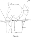
- Fig. 4A is an illustration 400A of the forces acting a knee.
- Fig. 4A illustrates a sagittal plane view of a simplified knee with two ligaments and two muscles for visualization purposes.
- Elements labeled with subscript " m " (e.g., f my , f mz ) represent muscle forces acting at the muscle tendon attachment sites.
- Elements labeled with subscript " c " (e.g., f cy , f cz ) represent actual contact forces of the prosthetic system under test.
- Elements labeled with subscript " s " (e.g., f sy , f sz ) represent soft tissue (e.g., ligament) forces.
- the passive force acting on the soft tissue is configuration or pose dependent (where configuration implies the relative position and orientation of the adjacent segments of the joint).
- pose refers to the current position and orientation of a rigid body in three-dimensional space relative to some reference frame (or reference pose).
- the attaching structural elements are elastically deformed such that tension is evoked in some or all of the elements. This tension may be resolved into orthogonal force components representing the passive (f passive ) forces.
- the passive forces are solely determined by the pose of the joint and may be calculated using an adequate structural model.
- a simulator machine (shown later in relation to Figs. 4D and 7 ) includes instrumentation to measure f contact (the real physical joint reaction force resulting from contact), while a control system (e.g., control system 300 shown in Fig. 3 ) is capable of calculating f passive using the soft tissue model and measurements of the current position and orientation of the prosthetic components.
- Equation ( f ) serves as the equilibrium relationship and may be considered as a kernel of a virtual soft tissue control.
- the soft tissue constraint model is a computational structural model of the joints soft tissue.
- the model includes computational algorithms that are used to calculate the tension in the connective tissue elements of the model.
- the geometry of the model is determined from measurements of the current position and orientation of the prosthetic components as those components are physically exercised in the simulator machine.
- the model may also include a database of geometrical and mechanical information representing the anatomical and physical properties of the natural knee soft tissues.
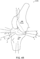
- Fig. 4B illustrates the coordinate systems and transformations 400B used by certain embodiments to describe knee motions adopted for use in a virtual soft tissue control system.
- Two coordinate systems, O T and OF, are defined, where O T is affixed to and moves with the tibia 491 and OF is affixed to and moves with the femur 492.
- the two coordinate origins are coincident and the x, y, and z axes are initially aligned.
- the orientation of the femur relative to the tibia is determined by angles ⁇ x , ⁇ y , and ⁇ z , which correspond to anatomical rotations of flexion-extension ( ⁇ x ), varus-valgus rotation ( ⁇ y ), and internal-external rotation ( ⁇ z ) respectively.
- the axes of the rotated femur are illustrated by x', y', and z'.
- a sequence of rotations taken through angles ⁇ x , ⁇ y , and ⁇ z about axes x, y, and z corresponds to a Cardan angle sequence (also known as Tait-Bryan angles).
- the matrix expression R defines a three-dimensional rotation of one rigid body relative to another.
- the current configuration of the femur relative to the tibia may be described by six variables, a x , a y , and a z and ⁇ x , ⁇ y , and ⁇ z , where the a x , a y , and a z terms represent the coordinates of a vector a extending from the tibial origin, O T , to the femur fixed origin, OF, and ⁇ x , ⁇ y , and ⁇ z terms represent the orientation of the femur 492 relative to the tibia 491, expressed in the three Cardan angles.
- Ligament tissue exhibits non-linear stress-strain behavior, hysteresis, rate dependent stiffness, stress relaxation, and creep.
- a phenomenological approximation may be used to govern the mechanical behavior of individual ligament fibers over a range of conditions relevant to normal physiological function.
- ligament may be better approximated by simple constitutive relationships with independent elastic and visco-elastic terms.
- the quadratic relationship ( h ) contains a time-independent quantity representing the strain-dependent stiffness (first term) and a time-dependent quantity providing strain-rate dependent stiffness and hysteresis (second term). This expression improves on equation ( i ), as it accommodates both strain-rate dependent stiffness and hysteresis behavior. This relationship is not a physical model and may have applicability limited to a bounded region of ligament behavior.
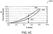
- Fig. 4C includes plots 400C that illustrate experimentally measured percentage strain 499 of ligaments along with an approximation 498 of this percentage strain obtained from equation ( h ).
- the modeled approximation closely follows the measured percentage strain over a wide strain range ( i.e. , at normal physiological strain rates).
- the damage threshold 497 represents a point at which significant ligament damage can occur. Any motion causing strain over the damage threshold may automatically terminate the test and cause a warning output.
- connective tissue joins the femoral and tibial segments of the joint and provides mechanical stability of the joint.
- This connective tissue includes ligaments bundles and sheath like capsular structures.
- the ligament bundles and sheath like structure in turn, include tough elastic collagen fibers. These structures are collectively referred to as the soft tissue structure of the joint.
- These soft tissues are attached to the bony structures at what are called insertion sites.
- the insertion sites tend to be well defined and extend over finite areas on the bony surface.
- the ligaments may be envisioned as bundles of a large number of fibers extending from the proximal to the distal insertion sites. It has been demonstrated that reasonable mechanical models may be devised by reducing the number of fibers to a few with well-chosen insertion sites representative of the insertion geometry of the natural knee.
- the mechanical properties of the ligaments are known from the testing of cadaveric ligament specimens.
- Each ligament may be subdivided into several fibers and be represented as a fiber bundle.
- Individual fibers of the bundle may be assigned elastic and visco-elastic properties so that the bundle collectively exhibits properties similar to the whole anatomical ligament.
- multi-fiber ligament model will herein be described in connection with knee prosthetics, the multi-fiber ligament model may be used in conjunction with any other prosthetics known in the art which may be surrounded by ligament or joints during implantation.
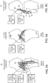
- Figs. 4D-a and 4D-b illustrate anatomical ligament insertion sites and their corresponding mathematical approximations.
- connective tissue joins the femoral and tibial segments of the joint and provides mechanical stability of the joint.
- This connective tissue consists of ligaments bundles and sheath like capsular structures, all comprised of tough elastic collagen fibers. These structures are collectively referred to as the soft tissue structure of the joint.
- These soft tissues are attached to the bony structures at what are called insertion sites.
- the insertion sites tend to be well defined and they extend over finite areas on the bony surface.
- the ligaments themselves may be envisioned as bundles of a large number of fibers extending from the proximal to the distal insertion sites.
- FIG. 4Db This modeling is illustrated for a single ligament structure, the deep layer of the MCL (medial collateral ligament) 444 in the Figure 4Da .
- the mathematical ligament approximation, shown in Fig. 4Db is composed from some number of independent fibers.
- Figure 4Db illustrates two fibers, the k th 446 and the k th+1 448 fibrils, which have been defined for the deep layer of the MCL.
- Prior work has demonstrated that two or three fibrils for each of the major ligament structures are sufficient for reasonably good approximation of the joints mechanical behavior.
- a database of information is maintained for the entire collection of fibrils.
- Proximal and distal insertion sites, p f [x, y, z] and p t [x, y, z] respectively, are defined for each fibril.
- the chosen insertion sites approximate the geometry of the anatomical insertion site of the ligament.
- Initial coordinates for the fibrils represent the position of the insertion site in a reference pose with the knee at full extension, bearing no load, and at a natural neutral internal rotation.
- the x, y, and z coordinates, referenced to the tibial frame ,OT, of each insertion site are stored for this reference pose.
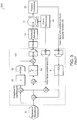
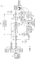
- FIG. 4E is a schematic of a control system 400E for a prosthetic simulator featuring a virtual soft tissue model in form of a multi-fiber ligament algorithm, according to certain embodiments.
- the virtual soft tissue algorithm may model the soft tissue constraints due to ligaments, joints, and capsular structures (e.g., in a knee).
- the soft tissue, or multi-fiber ligament model 102 establishes a relationship between the current configuration of the prosthetic in the simulator device (where configuration means the relative positions and orientation of the prosthetic components) and the constraint force which emulates the elastic restoring force of the knee's soft tissue and ligament structure.
- the biomechanical virtual soft tissue model may be based on a multi-fiber algorithmic description of the knee's ligament and capsular structure and incorporate the model in a closed loop control system for simulator control.
- the biomechanical virtual soft tissue model 102 may be used in place of cubic spline algorithm 8 shown in Fig. 3 . It should be appreciated that the simulator 101 of Fig. 4E may include equivalent components of the simulator 10 of Fig. 3 .
- the simulation of Fig. 4D includes a nested loop design featuring an inner loop 7 and an outer loop 9.
- the inner loop 7 utilizes feedback produced from the multi-axis force/torque transducer 19.
- the inner loop 7 also provides a traditional proportional integral derivative control (PID) via a discrete numeric algorithm 53.
- PID proportional integral derivative control
- the nested loop design also includes an outer loop 9, which utilizes feedback from the position transducer 21. This position feedback provides the input to the biomechanical model.
- Plural positions transducer 21 as well as orientation transducers may be used (position and angular displacement sensors).
- the angular inputs ⁇ x , ⁇ y , and ⁇ z correspond to flexion, varus-valgus, and internal rotation angles.
- the positional inputs a x , a y , and a z correspond to medial-lateral, anterior-posterior, and axial displacements of the prosthetic. These parameters are measured by appropriate position and orientation measurement instruments.
- the measured parameters all input to the multi-fiber ligament model 102 to permit calculation of the constraint force, including torque, with respect to each fiber, for any instant in time. Accordingly, within each iteration of the simulation of the soft tissue model, constraint force with respect to each fiber is calculated.
- the combination of the inner and outer loops functions as a feedback control system that drives the prosthetic drive mechanism.
- a measurement error from the previous iteration is employed to determine the drive signal for a subsequent iteration of the motion.
- the measurement error quantifies the difference between a driving waveform of the prosthetic device and a resulting force or motion of the prosthetic device.
- the control system may operate in time steps at a rate of 2000 Hz. Within the period between time steps, all of the required information is gathered and model and control calculations are performed. At the end of the time step period, all required control outputs are updated. At each time step the current configuration of the femur relative to the tibia is determined by position and angular sensors capable of measuring the three orthogonal position variables, a x , a y , and a z , and the three independent angle variables ⁇ x , ⁇ y , and ⁇ z .
- p j t and p j f denote position vectors from the tibial origin to the j th ligament insertion sites in the reference position, on the tibia p j t and the femur p j f .
- the terms ⁇ xj , ⁇ yj , and ⁇ zj denote the angles between the j th ligament fiber and the terms x, y, and z denote the axes of the tibial reference frame.
- the final step in the calculation of the soft tissue constraint is the summation of the individual fibril force and moment components into three orthogonal force components and three orthogonal moment components:
- F x is the medial-lateral constraint force
- F y is the anterior-posterior constraint force
- F x is the axial constraint force.
- the moment M x is close to zero as the joint provides little passive resistance to flexion-extension
- the moment M y is the resistance to varus-valgus rotation
- the moment M z is the resistance to axial rotation (internal-external rotation). This ensemble of forces and moments may be used to mitigate the control system drive-signals.
- Fig. 4F is a high-level illustration of procedures 400F involved in determining constraints encountered by displacement of the prosthetic element, with respect to each fiber, when implemented in the body.
- the current configuration of the prosthetic including angular inputs ⁇ x , ⁇ y , and ⁇ z and positional inputs a x , a y , and a z 402 are used to obtain factors relating to constraint force, including torque.
- a mathematical ligament approximation, as described above, may be composed of some number of independent fibers. First, length of each fiber, based on position of insertion points is calculated. Constraint force and torque, with respect to each fiber, for any instant of time, may also be calculated 403.
- corresponding ligament strain 420 values may be determined. For example, assuming that four ligament fibers, namely fibers A, B, C, and D are employed, corresponding strain values ⁇ A , ⁇ B , ⁇ C , and ⁇ D for each fiber may be determined. Using these strain values, corresponding ligament tension values, ⁇ A , ⁇ B , ⁇ C , and ⁇ D , are obtained. Elastic or visco-elastic properties of ligaments 409 may also be used to determine the ligament tension values 410. The tension values 410 are used to determine and resolve current forces on the prosthetic 402.
- the current configuration 402 may be used to determine a change in the position (i.e., displacement) of the prosthetic element, and eventually determine an error that quantifies the difference between a driving waveform of the prosthetic device and a resulting force or motion of the prosthetic device.
- the calculated error is used to determine the drive signal of the next iteration.
- the multi-fiber ligament soft tissue model may employ any number of ligament fibers with geometry and properties thereof providing information of the biomechanics of the knee.
- individual ligaments, one or more ligament structures or one or more groups of ligaments may be employed.
- Ligament structures may be chosen to correspond to what would be expected to result from actual medical procedures.
- proximal and distal insertion sites may be defined for each fiber.
- the chosen insertion sites approximate the geometry of the anatomical insertion site of the ligament.
- Initial coordinates for the fibers represent the position of the insertion site in a reference pose with the knee at full extension, bearing no load, and at a natural neutral internal rotation.
- the x, y, and z coordinates, referenced to the tibial frame, O T , of each insertion site may be stored for this reference pose.
- the database may further maintain information describing the mechanical characteristics of each ligament fiber as a set of fitting coefficients for the non-linear elastic behavior ( k 1 and k 2 ) and the strain rate dependent behavior ( k 3 ).
- the unstrained length, l 0 of each ligament fiber is defined.
- the ligament strain ⁇ may be determined using equation ( l ). Specifically, unstrained length or the initial distance between ligament insertion sites and extended distance between ligament insertion sites may be used.
- the multi-fiber ligament soft tissue model may include ligament fibers of the posteromedial 80 and/or the posterolateral 81 components.
- the posteromedial component 80 may include information on the geometry and properties of posteromedial ligament insertion sites 82, deep medial collateral 84, posterior capsule 85, and superficial medial collateral 86.
- the posterolateral component 81 may include information on the geometry and properties of posterolateral insertion sites 83, popliteo fibular 85, and lateral collateral 87.
- the multi-fiber ligament soft tissue model may consider the fact that fiber properties can change with movement. Other forces such as adjacent muscles and gravity may also be considered.
- the soft tissue model may also include ligament fibers connected between the femoral component 492 and the tibial component 491, as shown in Fig. 5B .
- Ligament fibers (a) and (b) represent the anterior cruciate 91 ligament ACL, which is normally resected during total knee arthroplasty (TKA).
- Ligament fibers (c) and (d) represent the portion of the posterior cruciate 92 ligament (PCL), which is dependent on cruciate sparing.
- Ligament fibers (e), (f), and (g) represent the lateral collateral ligament (LCL), while ligaments (h), (I), and (j) represent the medial collateral ligament (MCL).
- Ligaments (k) and (1) represent the posterior capsule.
- the posteromedial 80, posterolateral 81, femoral 90, and tibial 91 components may further include information on the geometry and properties of quadratic force-displacement; ligament force displacement; linear stiffness; aggregate tangent stiffness; and in situ strain.
- the biomechanical information employed in the multi-fiber ligament soft tissue model may be obtained through the use of cadaveric knee studies.
- ligaments constitute the major passive load bearing structure of the knee and when intact, these structures afford the knee mechanical stability.
- Surgical procedure and postoperative ligament condition impact the mechanical (and clinical) outcome of the procedure.
- Different implant devices and surgical strategies often require the removal of one or both of the anterior and posterior cruciate ligaments.
- the cruciate ligaments may be removed in the model to simulate surgical conditions.
- the condition and laxity of the medial collateral ligament layers may play a significant part in the kinematics of the joint.
- the laxity and stiffness of the modeled ligament fibers may also be adjusted to achieve the desired mechanical behavior.
- Each of the ligament structures requires one or more fibers for mechanical representation.
- Each fiber in turn requires the definition of the above geometrical and mechanical data in the software database.
- the modeled individual fibers are shown as dark lines with circles at the geometrical insertion sites.
- Each ligament may be modeled in software with a bundle comprised of multiple fibers each with its own mechanical properties and geometrical insertion site.
- Fig. 6A illustrates a natural knee 600.
- Fig. 6B illustrates a prosthetic knee 601 mounted in a simulator station.
- the rotational motions of the simulator are identified as ⁇ x , ⁇ y , and ⁇ z corresponding to anatomical rotations of flexion-extension, abduction-adduction and internal-external rotation.
- Translations along the x, y, and z axes correspond to anatomical medial-lateral, anterior-posterior and compression-distraction translations respectively.
- the joint reaction forces F x , F y , and F z and moments M x , M y , and M z are communicated to a multi-axis force transducer beneath the tibial component.
- the full computational model may be comprised of fifteen or more fibers (see Figs. 5A-5C ) that represent the seven primary ligaments and capsule structures.
- the simulator is comprised of a plurality of servo-hydraulic or electro-mechanical actuators that drive the rotational and translational motions. The motions may be monitored via a plurality of measurement instruments such as linear and rotary potentiometers to determine the current position and orientation of the femoral and tibial components. These position and orientation measurements along with the joint reaction forces and torques are filtered, conditioned, and digitized with an analog to digital converter. The digitized measurements are read by a digital signal processor system and are available to drive the control and computational algorithms.
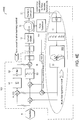
- Fig. 7 is an illustration 700 of certain embodiments of the invention that employ a feedback control system to perform soft tissue control.
- a similar high-level illustration of the control system in Fig. 4D Each controlled axis of motion is driven by a similar loop. The loop design is flexible to accommodate the different needs of the several actuator channels.
- An ensemble of kinetic and kinematic signals controls the motions and forces produced by the simulator machine (e.g ., reference waveform 6).
- Each reference waveform 6 may be a temporal series of data that governs the force, torque, displacement or angle (as appropriate to each channel) over one cycle of motion.
- the flexion motion may be placed under angular displacement control, internal-external rotation under torque control, while varus-valgus is permitted free rotation.
- Axial motion compression-distraction
- anterior-posterior displacement may be placed under force control while medial-lateral motion is permitted free translation.
- the axes of motion that are placed under force or torque control benefit from the virtual soft tissue control.
- the displacement controlled motions and the free motions do not directly rely on the virtual soft tissue model. However, these motions are monitored with suitable instruments to determine the current configuration of the prosthesis components.
- the control system 700 includes several nested control loops 710, 720, 730, 740 identified by A, B, C, and D.
- the corresponding feedback signals 71 OF, 720F, 730F are indicated FA, FB, FC and FD.
- the setup of the control system is very flexible and permits mapping of various feedback signals and or drive signals into different control channels.
- Loop 710 labeled as loop A, is the innermost loop. This loop is a position control loop used largely for control of the machine actuators during setup of samples prior to operation of the machine.
- the Mode Switch controls several gain and control law parameters to permit bump-less transfer between virtual soft tissue mode and position control mode.
- the value u (n) is the n th output sample supplied to the actuator, e (n) is the n th error sample, K p , K i , and K d are user settable gains for proportional, integral and derivative action of the control loop (PID) 750.
- this loop may be eliminated by setting the controller parameters to produce a transfer function of unity while forcing the feedback signal to null.
- Loop 720 labeled as loop B, is setup for force and/or torque control, depending on the actuator channel being controlled. Similar to loop A 710, this loop 720 is a standard form PID loop which implements the control law described by equations (r) and (s). In this case, y ref ( n ) reference input 6 will correspond to f active - f passive , which, as explained previously, is the balance of the force which must be supplied by the contact mechanics of the prosthesis to satisfy the force equilibrium requirement described in equation ( d ). The feedback signal at point FB 720F, corresponds to y ( n ) and is the measured contact force or torque representing the joint reaction force resulting from material contact of the prosthetic components.
- the signal f active - f p assive representing f contact may be calculated in another loop 730 (Loop C, described below). This difference is presented to summing junction S2 740, where the error signal is calculated by subtracting the measured contact force.
- the loop acts as a conventional force control loop and attempts to servo the measured contact force to a level equivalent to the active force less the passive force computed by the soft tissue model.
- Loop 730 relates to the soft tissue control system. This loop relies on the multi-fiber constraint model 755.
- the multi-fiber constraint model 755 accepts the current configuration 760 in terms of measured position ( A x , A y , and A z ) and orientation ( ⁇ x , ⁇ y , and ⁇ z ) measurements.
- the analytical calculations described above are carried out in real time ( e.g ., at 2000 samples per second) to determine the constraint outputs 770 in terms of passive force ( f x , f y , and f z ) and torque (m x , m y , and m z ) constraint values.
- a single model computational block may serve all channels.
- the model may accept six kinematic inputs 760 and produces six kinetic outputs 770.
- the kinetic outputs 770 are mapped to the proper actuator control channel to satisfy the equilibrium equation.
- the computed passive forces and torques 770 are subtracted from the active force signals at summing junction S1 745 in each of the six channels of the controller.
- four control channels namely channels for compression-distraction, anterior-posterior translation, medial-lateral translation, and internal-external rotation, are placed under virtual soft tissue control.
- the output of summing junction S1 745 represents the difference f active - f passive , which in turn is communicated to summing junction S2 740.
- Loop 790 labeled as loop D, is an iterative learning control (ILC) loop wrapped around the entire control loop.
- the ILC loop includes an iterative learning control algorithm 775 that acts on entire sets of data representing one cycle of motion of the simulator.
- the ILC algorithm 775 has several memory arrays that maintain a full cycle of data over the period of the modeled activity.
- An error signal e p (t) is maintained in one memory array, while a second array is used to accumulate a feed forward signal, which is summed with the real time control signal at summing junction S4 747.
- the joint reaction force may be dominated by frictional force.
- the complex motions result is multiple motion reversals during the course of one cycle, and at each motion reversal, breakaway forces may occur.
- frictional breakaway is accompanied by chatter and noise and high instantaneous force levels. Under strict PID control, these anomalies are difficult to impossible to control.
- the ILC algorithm 775 overcomes these difficulties and facilitates smooth accurate tracking performance.
Landscapes
- Engineering & Computer Science (AREA)
- Physics & Mathematics (AREA)
- General Physics & Mathematics (AREA)
- Mathematical Analysis (AREA)
- Mathematical Physics (AREA)
- Medicinal Chemistry (AREA)
- General Health & Medical Sciences (AREA)
- Algebra (AREA)
- Computational Mathematics (AREA)
- Chemical & Material Sciences (AREA)
- Health & Medical Sciences (AREA)
- Mathematical Optimization (AREA)
- Medical Informatics (AREA)
- Pure & Applied Mathematics (AREA)
- Business, Economics & Management (AREA)
- Educational Administration (AREA)
- Educational Technology (AREA)
- Theoretical Computer Science (AREA)
- Prostheses (AREA)
- Instructional Devices (AREA)
- Feedback Control In General (AREA)
- Manipulator (AREA)
Claims (13)
- Simulator (10) zum Antreiben eines Protheseelements (11), der Folgendes umfasst:einen Protheseantriebsmechanismus (15), der das Protheseelement (11) antreibt;einen Sensor (19), der die auf das Protheseelement ausgeübte Kraft misst; undein Rückkopplungsregelsystem (400E, 700), das auf den Sensor und eine Simulationseingabe (6) reagiert, um den Protheseantriebsmechanismus anzutreiben, wobei das Regelsystem ein Berechnungsmodell (102, 755) beinhaltet, das eine Darstellung eines Gelenkbands einbindet, dadurch gekennzeichnet, dass die Darstellung die dreidimensionale Geometrie und die mechanischen Eigenschaften des Gelenkbands beinhaltet.
- Verfahren zum Antreiben eines Protheseelements (11) in einem Simulator (10), wobei das Verfahren Folgendes umfasst:Anwenden einer Simulationseingabe (6) auf ein Regelsystem (400E, 700), das das Protheseelement (11) antreibt;Erfassen einer auf das Protheseelement ausgeübten Kraft (19);Erfassen einer Verlagerung (21) des Protheseelements;Reagieren auf die erfasste Verlagerung in einem Berechnungsmodell (102, 755), das eine Darstellung eines Gelenkbands einbindet, um Zwangskräfte des Gelenkbands zu bestimmen;Kombinieren der Simulationseingabe mit den bestimmten Zwangskräften und der gemessenen Kraft beim Antreiben des Protheseelements, dadurch gekennzeichnet, dass die Darstellung die dreidimensionale Geometrie und die mechanischen Eigenschaften des Gelenkbands beinhaltet.
- Simulator nach Anspruch 1 oder Verfahren nach Anspruch 2, wobei die Geometrie des Gelenkbands durch Einführungsstellen an geeigneten, beispielsweise entgegengesetzten Enden des Gelenkbands definiert ist.
- Simulator oder Verfahren nach einem vorhergehenden Anspruch, wobei die mechanischen Eigenschaften des Gelenkbands mindestens eine von elastischen oder viskoelastischen Eigenschaften des Gelenkbands beinhalten.
- Simulator oder Verfahren nach einem vorhergehenden Anspruch, wobei die Darstellung Eigenschaften unterschiedlicher Fasern des Gelenkbands beinhaltet.
- Simulator oder Verfahren nach Anspruch 5, wobei jede Faser unterschiedliche Einführungsstellen beinhaltet.
- Simulator oder Verfahren nach einem vorhergehenden Anspruch, weiterhin wobei Verlagerungssensoren (21) vorgesehen sind, die eine Verlagerung des Protheseelements (11) messen.
- Simulator oder Verfahren nach Anspruch 7, wobei die Verlagerungssensoren (21) Positions- und Winkelverlagerungssensoren beinhalten.
- Simulator oder Verfahren nach Anspruch 7 oder 8, wobei das Modell (102, 755) auf die Verlagerungssensoren (21) reagiert, um Zwangskräfte oder Drehmomente von Gelenkbändern zu bestimmen, die eine Wirkung des Regelsystems (400E, 700) abschwächen.
- Simulator oder Verfahren nach einem vorhergehenden Anspruch, wobei das Regelsystem (400E, 700) ein geschachteltes Schleifendesign umfasst.
- Simulator (10) zum Antreiben eines Protheseelements (11) nach Anspruch 1, der Folgendes umfasst:Positions- und Winkelverlagerungssensoren (21), die eine Verlagerung des Protheseelements (11) messen;eine Simulationseingabe (6), die eine Wirkung des Simulators (10) darstellt; undwobei das Regelsystem (400E, 700) ein Rückkopplungsregelsystem mit geschlossenem Regelkreis ist, das auf die Sensoren reagiert, um ein Antriebssignal für den Antriebsmechanismus (15) zu bestimmen, wobei das Berechnungsmodell (102, 755) mechanische Darstellungen von Gelenkbandfasern einbindet, einschließlich der dreidimensionalen Geometrie von Einführungsstellen und der mechanischen Eigenschaften von Gelenkbandfasern, wobei das Modell auf die Positions- und Winkelverlagerungssensoren reagiert, um Zwangskräfte von Gelenkbändern zu bestimmen, wobei das Regelsystem die bestimmten Zwangskräfte und die gemessene Kraft mit der Simulationseingabe kombiniert.
- Regelsystem (400E, 700) zur Verwendung in einem Simulator (10) nach Anspruch 1, wobei das Regelsystem ein Berechnungsmodell (102, 755) beinhaltet, das Darstellungen eines Gelenkbands einbindet, wobei die Darstellung die dreidimensionale Geometrie und die mechanischen Eigenschaften des Gelenkbands beinhaltet.
- Regelsystem nach Anspruch 12, wobei die Darstellungen eines Gelenkbands dreidimensionale Einführungsstellen beinhalten.
Applications Claiming Priority (3)
| Application Number | Priority Date | Filing Date | Title |
|---|---|---|---|
| US25936009P | 2009-11-09 | 2009-11-09 | |
| US28667209P | 2009-12-15 | 2009-12-15 | |
| PCT/US2010/056062 WO2011057285A2 (en) | 2009-11-09 | 2010-11-09 | System and method for joint motion simulation |
Publications (2)
| Publication Number | Publication Date |
|---|---|
| EP2494416A2 EP2494416A2 (de) | 2012-09-05 |
| EP2494416B1 true EP2494416B1 (de) | 2017-01-04 |
Family
ID=43846352
Family Applications (1)
| Application Number | Title | Priority Date | Filing Date |
|---|---|---|---|
| EP10788431.4A Active EP2494416B1 (de) | 2009-11-09 | 2010-11-09 | System und verfahren für die simulation von gelenkbewegungen |
Country Status (9)
| Country | Link |
|---|---|
| US (1) | US8805662B2 (de) |
| EP (1) | EP2494416B1 (de) |
| JP (1) | JP5698757B2 (de) |
| KR (1) | KR101829016B1 (de) |
| CN (1) | CN102687183B (de) |
| AU (1) | AU2010314879B2 (de) |
| BR (1) | BR112012010980B1 (de) |
| CA (1) | CA2779013C (de) |
| WO (1) | WO2011057285A2 (de) |
Families Citing this family (19)
| Publication number | Priority date | Publication date | Assignee | Title |
|---|---|---|---|---|
| BR112013011963B1 (pt) | 2010-11-15 | 2021-05-18 | Advanced Mechanical Technology, Inc. | simulador de movimento articulado e método para conduzir um dispositivo protético |
| US9642725B2 (en) | 2011-11-14 | 2017-05-09 | Advanced Mechanical Technology, Inc. | System and method for joint testing |
| JP6144529B2 (ja) * | 2013-04-22 | 2017-06-07 | 西島メディカル株式会社 | 人工関節摩擦摩耗試験機、人工関節摩擦摩耗試験機の制御方法 |
| US9629580B2 (en) * | 2014-03-19 | 2017-04-25 | Advanced Mechanical Technology, Inc. | System and method for ligament insertion in knee joint surgeries using adaptive migration of ligament insertion geometry |
| KR101705199B1 (ko) * | 2015-05-12 | 2017-02-09 | 주식회사 코어라인소프트 | 의료 영상을 이용한 전방십자인대 재건 수술의 시뮬레이션 시스템 및 방법 |
| WO2016195363A1 (ko) * | 2015-06-01 | 2016-12-08 | 고려대학교 산학협력단 | 의료영상장비 내에서 구동 가능한 관절 시뮬레이터 |
| KR101780552B1 (ko) | 2015-06-01 | 2017-09-21 | 고려대학교 산학협력단 | 의료영상장비 내에서 구동 가능한 관절 시뮬레이터 |
| US10198968B2 (en) | 2015-12-07 | 2019-02-05 | Hospital For Special Surgery | Method for creating a computer model of a joint for treatment planning |
| US10420691B2 (en) | 2016-02-24 | 2019-09-24 | Richard Stewart | Knee range of motion device utilizing tangential joint translation and distraction |
| US10286550B2 (en) * | 2016-12-02 | 2019-05-14 | National Taipei University Of Technology | Robot teaching system and control method thereof |
| AU2020235100B2 (en) * | 2019-03-12 | 2025-07-03 | Mako Surgical Corp. | Systems and methods for robotic soft tissue evaluation |
| FR3102866B1 (fr) * | 2019-10-30 | 2021-10-01 | Safran Electronics & Defense | Procédé de commande d’un actionneur de système mécanique à frottements imbriqués |
| US12277867B2 (en) | 2020-03-03 | 2025-04-15 | Howmedica Osteonics Corp. | Enhanced human joint simulation model |
| WO2022017583A1 (en) * | 2020-07-21 | 2022-01-27 | Ottobock Se & Co. Kgaa | Method for controlling an orthopedic device and orthopedic device |
| CN112378634B (zh) * | 2020-11-11 | 2022-06-10 | 德检(江苏)检测技术有限公司 | 一种人工膝关节假体约束力测试专用工装 |
| KR102546160B1 (ko) | 2021-09-17 | 2023-06-22 | 인하대학교 산학협력단 | 입자기반 유체의 특성을 활용한 관절 탄성 시뮬레이션 방법 및 장치 |
| JP7756912B2 (ja) * | 2022-01-24 | 2025-10-21 | 日本ヘルスケアエンジニア協会合同会社 | 股関節手術シミュレーション装置およびその使用方法 |
| CN118692297A (zh) * | 2024-07-24 | 2024-09-24 | 汕头大学医学院第二附属医院 | 一种可调节式困难气道综合训练模型 |
| CN121281362B (zh) * | 2025-12-11 | 2026-03-24 | 福州大学附属省立医院 | 一种关节训练模型 |
Family Cites Families (5)
| Publication number | Priority date | Publication date | Assignee | Title |
|---|---|---|---|---|
| US5014719A (en) | 1984-02-02 | 1991-05-14 | Mcleod Paul C | Knee loading and testing apparatus and method |
| AT393954B (de) * | 1990-02-28 | 1992-01-10 | Bock Orthopaed Ind | Verfahren und vorrichtung zur bestimmung von gebrauchseigenschaften eines prothesenschaftes |
| US7823460B2 (en) | 2005-08-12 | 2010-11-02 | Advanced Mechanical Technology, Inc. | Prosthetic simulator with soft tissue modeling |
| AU2006339993A1 (en) | 2006-03-14 | 2007-09-20 | Mako Surgical Corp. | Prosthetic device and system and method for implanting prosthetic device |
| CN101357085B (zh) * | 2008-09-23 | 2010-12-08 | 上海理工大学 | 下肢假肢步态试验装置 |
-
2010
- 2010-11-09 EP EP10788431.4A patent/EP2494416B1/de active Active
- 2010-11-09 CA CA2779013A patent/CA2779013C/en active Active
- 2010-11-09 US US12/942,886 patent/US8805662B2/en active Active
- 2010-11-09 AU AU2010314879A patent/AU2010314879B2/en active Active
- 2010-11-09 CN CN201080050779.8A patent/CN102687183B/zh active Active
- 2010-11-09 BR BR112012010980A patent/BR112012010980B1/pt active IP Right Grant
- 2010-11-09 KR KR1020127014899A patent/KR101829016B1/ko active Active
- 2010-11-09 WO PCT/US2010/056062 patent/WO2011057285A2/en not_active Ceased
- 2010-11-09 JP JP2012538091A patent/JP5698757B2/ja active Active
Also Published As
| Publication number | Publication date |
|---|---|
| CN102687183B (zh) | 2016-04-20 |
| KR20120099068A (ko) | 2012-09-06 |
| KR101829016B1 (ko) | 2018-02-13 |
| BR112012010980A2 (pt) | 2018-07-24 |
| US8805662B2 (en) | 2014-08-12 |
| WO2011057285A3 (en) | 2011-08-04 |
| CN102687183A (zh) | 2012-09-19 |
| US20110118878A1 (en) | 2011-05-19 |
| AU2010314879B2 (en) | 2014-07-17 |
| CA2779013A1 (en) | 2011-05-12 |
| JP2013509975A (ja) | 2013-03-21 |
| JP5698757B2 (ja) | 2015-04-08 |
| EP2494416A2 (de) | 2012-09-05 |
| AU2010314879A1 (en) | 2012-05-10 |
| CA2779013C (en) | 2018-03-13 |
| WO2011057285A2 (en) | 2011-05-12 |
| BR112012010980B1 (pt) | 2020-01-21 |
Similar Documents
| Publication | Publication Date | Title |
|---|---|---|
| US8805662B2 (en) | System and method for joint motion simulation | |
| King | A technical survey: A review of biomechanical models | |
| Yamaguchi | Performing whole-body simulations of gait with 3-D, dynamic musculoskeletal models | |
| Van den Bogert | Analysis and simulation of mechanical loads on the human musculoskeletal system: a methodological overview | |
| Haider | Tribological assessment of UHMWPE in the knee | |
| Favre et al. | Changes in shoulder muscle function with humeral position: a graphical description | |
| DeWoody et al. | A forward dynamic model of gait with application to stress analysis of bone | |
| Herrmann et al. | HiL simulation in biomechanics: a new approach for testing total joint replacements | |
| HK1168666A (en) | System and method for joint motion simulation | |
| HK1168666B (en) | System and method for joint motion simulation | |
| Xin et al. | Computational biomechanical modelling of the spine | |
| Tigue et al. | Simulating tendon shortening during flexor tendon repair surgery using a biomechanical model and robotic testbed | |
| Borotikar | Subject specific computational models of the knee to predict anterior cruciate ligament injury | |
| Hollis | A six-degree-of-freedom test system for the study of joint mechanics and ligament forces | |
| Schovanec | Ocular dynamics and skeletal systems | |
| Tigue | Finger Flexor Tendon Repair Surgery: Simulation and Analysis Using a Biomimetic Robot, a Cadaver Testbed, and a Computational Model | |
| Deane et al. | Anatomically Accurate Motorized Shoulder Model with Scapula Movement | |
| Stanev | Biomechanical simulation of virtual physiological humans: modeling of musculoskeletal kinematic and dynamic redundancy using coordinate projection methods | |
| Tändl et al. | An integrated simulation environment for human gait analysis and evaluation | |
| Kong et al. | Design and experimental study of a rigid-flexible coupled back rehabilitation robot | |
| Al-Haifi | Design and manufacture of a universal mechanical human joint simulator | |
| Debski et al. | Experimental and computational modeling of joint and ligament mechanics | |
| Olanlokun et al. | A spatial model of the knee for the preoperative planning of knee surgery | |
| Hume | Translating Data from the Laboratory into Simulation: A Computational Framework for Subject-Specific Finite Element Musculoskeletal Simulation | |
| Hungenahalli Shivanna | Musculoskeletal Modeling of Ballet |
Legal Events
| Date | Code | Title | Description |
|---|---|---|---|
| PUAI | Public reference made under article 153(3) epc to a published international application that has entered the european phase |
Free format text: ORIGINAL CODE: 0009012 |
|
| 17P | Request for examination filed |
Effective date: 20120531 |
|
| AK | Designated contracting states |
Kind code of ref document: A2 Designated state(s): AL AT BE BG CH CY CZ DE DK EE ES FI FR GB GR HR HU IE IS IT LI LT LU LV MC MK MT NL NO PL PT RO RS SE SI SK SM TR |
|
| REG | Reference to a national code |
Ref country code: HK Ref legal event code: DE Ref document number: 1168666 Country of ref document: HK |
|
| DAX | Request for extension of the european patent (deleted) | ||
| 17Q | First examination report despatched |
Effective date: 20130619 |
|
| REG | Reference to a national code |
Ref country code: DE Ref legal event code: R079 Ref document number: 602010039375 Country of ref document: DE Free format text: PREVIOUS MAIN CLASS: G05B0015000000 Ipc: G09B0023320000 |
|
| GRAP | Despatch of communication of intention to grant a patent |
Free format text: ORIGINAL CODE: EPIDOSNIGR1 |
|
| RIC1 | Information provided on ipc code assigned before grant |
Ipc: G09B 23/32 20060101AFI20160523BHEP |
|
| INTG | Intention to grant announced |
Effective date: 20160624 |
|
| GRAS | Grant fee paid |
Free format text: ORIGINAL CODE: EPIDOSNIGR3 |
|
| GRAA | (expected) grant |
Free format text: ORIGINAL CODE: 0009210 |
|
| STAA | Information on the status of an ep patent application or granted ep patent |
Free format text: STATUS: THE PATENT HAS BEEN GRANTED |
|
| AK | Designated contracting states |
Kind code of ref document: B1 Designated state(s): AL AT BE BG CH CY CZ DE DK EE ES FI FR GB GR HR HU IE IS IT LI LT LU LV MC MK MT NL NO PL PT RO RS SE SI SK SM TR |
|
| REG | Reference to a national code |
Ref country code: GB Ref legal event code: FG4D |
|
| REG | Reference to a national code |
Ref country code: CH Ref legal event code: EP |
|
| REG | Reference to a national code |
Ref country code: AT Ref legal event code: REF Ref document number: 859921 Country of ref document: AT Kind code of ref document: T Effective date: 20170115 |
|
| REG | Reference to a national code |
Ref country code: IE Ref legal event code: FG4D |
|
| REG | Reference to a national code |
Ref country code: DE Ref legal event code: R096 Ref document number: 602010039375 Country of ref document: DE |
|
| REG | Reference to a national code |
Ref country code: NL Ref legal event code: FP |
|
| REG | Reference to a national code |
Ref country code: LT Ref legal event code: MG4D |
|
| REG | Reference to a national code |
Ref country code: AT Ref legal event code: MK05 Ref document number: 859921 Country of ref document: AT Kind code of ref document: T Effective date: 20170104 |
|
| PG25 | Lapsed in a contracting state [announced via postgrant information from national office to epo] |
Ref country code: IS Free format text: LAPSE BECAUSE OF FAILURE TO SUBMIT A TRANSLATION OF THE DESCRIPTION OR TO PAY THE FEE WITHIN THE PRESCRIBED TIME-LIMIT Effective date: 20170504 Ref country code: LT Free format text: LAPSE BECAUSE OF FAILURE TO SUBMIT A TRANSLATION OF THE DESCRIPTION OR TO PAY THE FEE WITHIN THE PRESCRIBED TIME-LIMIT Effective date: 20170104 Ref country code: FI Free format text: LAPSE BECAUSE OF FAILURE TO SUBMIT A TRANSLATION OF THE DESCRIPTION OR TO PAY THE FEE WITHIN THE PRESCRIBED TIME-LIMIT Effective date: 20170104 Ref country code: NO Free format text: LAPSE BECAUSE OF FAILURE TO SUBMIT A TRANSLATION OF THE DESCRIPTION OR TO PAY THE FEE WITHIN THE PRESCRIBED TIME-LIMIT Effective date: 20170404 Ref country code: HR Free format text: LAPSE BECAUSE OF FAILURE TO SUBMIT A TRANSLATION OF THE DESCRIPTION OR TO PAY THE FEE WITHIN THE PRESCRIBED TIME-LIMIT Effective date: 20170104 Ref country code: GR Free format text: LAPSE BECAUSE OF FAILURE TO SUBMIT A TRANSLATION OF THE DESCRIPTION OR TO PAY THE FEE WITHIN THE PRESCRIBED TIME-LIMIT Effective date: 20170405 |
|
| PG25 | Lapsed in a contracting state [announced via postgrant information from national office to epo] |
Ref country code: SE Free format text: LAPSE BECAUSE OF FAILURE TO SUBMIT A TRANSLATION OF THE DESCRIPTION OR TO PAY THE FEE WITHIN THE PRESCRIBED TIME-LIMIT Effective date: 20170104 Ref country code: RS Free format text: LAPSE BECAUSE OF FAILURE TO SUBMIT A TRANSLATION OF THE DESCRIPTION OR TO PAY THE FEE WITHIN THE PRESCRIBED TIME-LIMIT Effective date: 20170104 Ref country code: AT Free format text: LAPSE BECAUSE OF FAILURE TO SUBMIT A TRANSLATION OF THE DESCRIPTION OR TO PAY THE FEE WITHIN THE PRESCRIBED TIME-LIMIT Effective date: 20170104 Ref country code: BG Free format text: LAPSE BECAUSE OF FAILURE TO SUBMIT A TRANSLATION OF THE DESCRIPTION OR TO PAY THE FEE WITHIN THE PRESCRIBED TIME-LIMIT Effective date: 20170404 Ref country code: ES Free format text: LAPSE BECAUSE OF FAILURE TO SUBMIT A TRANSLATION OF THE DESCRIPTION OR TO PAY THE FEE WITHIN THE PRESCRIBED TIME-LIMIT Effective date: 20170104 Ref country code: LV Free format text: LAPSE BECAUSE OF FAILURE TO SUBMIT A TRANSLATION OF THE DESCRIPTION OR TO PAY THE FEE WITHIN THE PRESCRIBED TIME-LIMIT Effective date: 20170104 Ref country code: PL Free format text: LAPSE BECAUSE OF FAILURE TO SUBMIT A TRANSLATION OF THE DESCRIPTION OR TO PAY THE FEE WITHIN THE PRESCRIBED TIME-LIMIT Effective date: 20170104 Ref country code: PT Free format text: LAPSE BECAUSE OF FAILURE TO SUBMIT A TRANSLATION OF THE DESCRIPTION OR TO PAY THE FEE WITHIN THE PRESCRIBED TIME-LIMIT Effective date: 20170504 |
|
| REG | Reference to a national code |
Ref country code: DE Ref legal event code: R097 Ref document number: 602010039375 Country of ref document: DE |
|
| PG25 | Lapsed in a contracting state [announced via postgrant information from national office to epo] |
Ref country code: IT Free format text: LAPSE BECAUSE OF FAILURE TO SUBMIT A TRANSLATION OF THE DESCRIPTION OR TO PAY THE FEE WITHIN THE PRESCRIBED TIME-LIMIT Effective date: 20170104 Ref country code: RO Free format text: LAPSE BECAUSE OF FAILURE TO SUBMIT A TRANSLATION OF THE DESCRIPTION OR TO PAY THE FEE WITHIN THE PRESCRIBED TIME-LIMIT Effective date: 20170104 Ref country code: SK Free format text: LAPSE BECAUSE OF FAILURE TO SUBMIT A TRANSLATION OF THE DESCRIPTION OR TO PAY THE FEE WITHIN THE PRESCRIBED TIME-LIMIT Effective date: 20170104 Ref country code: CZ Free format text: LAPSE BECAUSE OF FAILURE TO SUBMIT A TRANSLATION OF THE DESCRIPTION OR TO PAY THE FEE WITHIN THE PRESCRIBED TIME-LIMIT Effective date: 20170104 Ref country code: EE Free format text: LAPSE BECAUSE OF FAILURE TO SUBMIT A TRANSLATION OF THE DESCRIPTION OR TO PAY THE FEE WITHIN THE PRESCRIBED TIME-LIMIT Effective date: 20170104 |
|
| PLBE | No opposition filed within time limit |
Free format text: ORIGINAL CODE: 0009261 |
|
| STAA | Information on the status of an ep patent application or granted ep patent |
Free format text: STATUS: NO OPPOSITION FILED WITHIN TIME LIMIT |
|
| REG | Reference to a national code |
Ref country code: FR Ref legal event code: PLFP Year of fee payment: 8 |
|
| PG25 | Lapsed in a contracting state [announced via postgrant information from national office to epo] |
Ref country code: DK Free format text: LAPSE BECAUSE OF FAILURE TO SUBMIT A TRANSLATION OF THE DESCRIPTION OR TO PAY THE FEE WITHIN THE PRESCRIBED TIME-LIMIT Effective date: 20170104 Ref country code: SM Free format text: LAPSE BECAUSE OF FAILURE TO SUBMIT A TRANSLATION OF THE DESCRIPTION OR TO PAY THE FEE WITHIN THE PRESCRIBED TIME-LIMIT Effective date: 20170104 |
|
| 26N | No opposition filed |
Effective date: 20171005 |
|
| PG25 | Lapsed in a contracting state [announced via postgrant information from national office to epo] |
Ref country code: SI Free format text: LAPSE BECAUSE OF FAILURE TO SUBMIT A TRANSLATION OF THE DESCRIPTION OR TO PAY THE FEE WITHIN THE PRESCRIBED TIME-LIMIT Effective date: 20170104 |
|
| REG | Reference to a national code |
Ref country code: HK Ref legal event code: GR Ref document number: 1168666 Country of ref document: HK |
|
| PG25 | Lapsed in a contracting state [announced via postgrant information from national office to epo] |
Ref country code: MC Free format text: LAPSE BECAUSE OF FAILURE TO SUBMIT A TRANSLATION OF THE DESCRIPTION OR TO PAY THE FEE WITHIN THE PRESCRIBED TIME-LIMIT Effective date: 20170104 |
|
| PG25 | Lapsed in a contracting state [announced via postgrant information from national office to epo] |
Ref country code: LI Free format text: LAPSE BECAUSE OF NON-PAYMENT OF DUE FEES Effective date: 20171130 Ref country code: CH Free format text: LAPSE BECAUSE OF NON-PAYMENT OF DUE FEES Effective date: 20171130 |
|
| PG25 | Lapsed in a contracting state [announced via postgrant information from national office to epo] |
Ref country code: LU Free format text: LAPSE BECAUSE OF NON-PAYMENT OF DUE FEES Effective date: 20171109 |
|
| REG | Reference to a national code |
Ref country code: BE Ref legal event code: MM Effective date: 20171130 |
|
| REG | Reference to a national code |
Ref country code: IE Ref legal event code: MM4A |
|
| PG25 | Lapsed in a contracting state [announced via postgrant information from national office to epo] |
Ref country code: MT Free format text: LAPSE BECAUSE OF NON-PAYMENT OF DUE FEES Effective date: 20171109 |
|
| REG | Reference to a national code |
Ref country code: FR Ref legal event code: PLFP Year of fee payment: 9 |
|
| PG25 | Lapsed in a contracting state [announced via postgrant information from national office to epo] |
Ref country code: IE Free format text: LAPSE BECAUSE OF NON-PAYMENT OF DUE FEES Effective date: 20171109 |
|
| PG25 | Lapsed in a contracting state [announced via postgrant information from national office to epo] |
Ref country code: BE Free format text: LAPSE BECAUSE OF NON-PAYMENT OF DUE FEES Effective date: 20171130 |
|
| REG | Reference to a national code |
Ref country code: DE Ref legal event code: R082 Ref document number: 602010039375 Country of ref document: DE Representative=s name: PAGE, WHITE & FARRER GERMANY LLP, DE |
|
| PG25 | Lapsed in a contracting state [announced via postgrant information from national office to epo] |
Ref country code: HU Free format text: LAPSE BECAUSE OF FAILURE TO SUBMIT A TRANSLATION OF THE DESCRIPTION OR TO PAY THE FEE WITHIN THE PRESCRIBED TIME-LIMIT; INVALID AB INITIO Effective date: 20101109 |
|
| PG25 | Lapsed in a contracting state [announced via postgrant information from national office to epo] |
Ref country code: CY Free format text: LAPSE BECAUSE OF NON-PAYMENT OF DUE FEES Effective date: 20170104 |
|
| PG25 | Lapsed in a contracting state [announced via postgrant information from national office to epo] |
Ref country code: MK Free format text: LAPSE BECAUSE OF FAILURE TO SUBMIT A TRANSLATION OF THE DESCRIPTION OR TO PAY THE FEE WITHIN THE PRESCRIBED TIME-LIMIT Effective date: 20170104 |
|
| PG25 | Lapsed in a contracting state [announced via postgrant information from national office to epo] |
Ref country code: TR Free format text: LAPSE BECAUSE OF FAILURE TO SUBMIT A TRANSLATION OF THE DESCRIPTION OR TO PAY THE FEE WITHIN THE PRESCRIBED TIME-LIMIT Effective date: 20170104 |
|
| PG25 | Lapsed in a contracting state [announced via postgrant information from national office to epo] |
Ref country code: AL Free format text: LAPSE BECAUSE OF FAILURE TO SUBMIT A TRANSLATION OF THE DESCRIPTION OR TO PAY THE FEE WITHIN THE PRESCRIBED TIME-LIMIT Effective date: 20170104 |
|
| PGFP | Annual fee paid to national office [announced via postgrant information from national office to epo] |
Ref country code: NL Payment date: 20251024 Year of fee payment: 16 |
|
| REG | Reference to a national code |
Ref country code: DE Ref legal event code: R082 Ref document number: 602010039375 Country of ref document: DE Representative=s name: WESTPHAL, MUSSGNUG & PARTNER PATENTANWAELTE MI, DE |
|
| PGFP | Annual fee paid to national office [announced via postgrant information from national office to epo] |
Ref country code: DE Payment date: 20251014 Year of fee payment: 16 |
|
| PGFP | Annual fee paid to national office [announced via postgrant information from national office to epo] |
Ref country code: GB Payment date: 20251016 Year of fee payment: 16 |
|
| PGFP | Annual fee paid to national office [announced via postgrant information from national office to epo] |
Ref country code: FR Payment date: 20251023 Year of fee payment: 16 |