EP2492948A1 - X-ray generator - Google Patents
X-ray generator Download PDFInfo
- Publication number
- EP2492948A1 EP2492948A1 EP12003029A EP12003029A EP2492948A1 EP 2492948 A1 EP2492948 A1 EP 2492948A1 EP 12003029 A EP12003029 A EP 12003029A EP 12003029 A EP12003029 A EP 12003029A EP 2492948 A1 EP2492948 A1 EP 2492948A1
- Authority
- EP
- European Patent Office
- Prior art keywords
- anticathode
- conductive
- rotary
- brush
- case
- Prior art date
- Legal status (The legal status is an assumption and is not a legal conclusion. Google has not performed a legal analysis and makes no representation as to the accuracy of the status listed.)
- Granted
Links
- 229920001410 Microfiber Polymers 0.000 claims abstract description 47
- 239000003658 microfiber Substances 0.000 claims abstract description 47
- 239000000835 fiber Substances 0.000 claims abstract description 44
- 239000000498 cooling water Substances 0.000 claims abstract description 14
- 230000002093 peripheral effect Effects 0.000 claims abstract description 14
- XLYOFNOQVPJJNP-UHFFFAOYSA-N water Substances O XLYOFNOQVPJJNP-UHFFFAOYSA-N 0.000 claims abstract description 13
- 238000001816 cooling Methods 0.000 claims abstract description 8
- 238000005342 ion exchange Methods 0.000 claims abstract description 6
- 238000005096 rolling process Methods 0.000 claims abstract description 6
- 239000011810 insulating material Substances 0.000 claims abstract description 4
- 229920002972 Acrylic fiber Polymers 0.000 claims description 2
- OMZSGWSJDCOLKM-UHFFFAOYSA-N copper(II) sulfide Chemical compound [S-2].[Cu+2] OMZSGWSJDCOLKM-UHFFFAOYSA-N 0.000 claims description 2
- 238000005260 corrosion Methods 0.000 abstract description 12
- 230000007797 corrosion Effects 0.000 abstract description 12
- 125000006850 spacer group Chemical group 0.000 description 9
- 230000001965 increasing effect Effects 0.000 description 8
- 239000003507 refrigerant Substances 0.000 description 7
- 208000035874 Excoriation Diseases 0.000 description 6
- 238000005299 abrasion Methods 0.000 description 6
- 239000000843 powder Substances 0.000 description 6
- 239000000919 ceramic Substances 0.000 description 4
- 238000000638 solvent extraction Methods 0.000 description 4
- 230000003247 decreasing effect Effects 0.000 description 3
- 238000005549 size reduction Methods 0.000 description 3
- 229910000831 Steel Inorganic materials 0.000 description 2
- 239000010959 steel Substances 0.000 description 2
- OKTJSMMVPCPJKN-UHFFFAOYSA-N Carbon Chemical compound [C] OKTJSMMVPCPJKN-UHFFFAOYSA-N 0.000 description 1
- 229910052799 carbon Inorganic materials 0.000 description 1
- 238000010000 carbonizing Methods 0.000 description 1
- 230000015556 catabolic process Effects 0.000 description 1
- 239000004020 conductor Substances 0.000 description 1
- 230000007423 decrease Effects 0.000 description 1
- 230000000694 effects Effects 0.000 description 1
- 238000010894 electron beam technology Methods 0.000 description 1
- 230000002708 enhancing effect Effects 0.000 description 1
Images


Classifications
-
- H—ELECTRICITY
- H01—ELECTRIC ELEMENTS
- H01J—ELECTRIC DISCHARGE TUBES OR DISCHARGE LAMPS
- H01J35/00—X-ray tubes
- H01J35/24—Tubes wherein the point of impact of the cathode ray on the anode or anticathode is movable relative to the surface thereof
- H01J35/26—Tubes wherein the point of impact of the cathode ray on the anode or anticathode is movable relative to the surface thereof by rotation of the anode or anticathode
-
- H—ELECTRICITY
- H01—ELECTRIC ELEMENTS
- H01J—ELECTRIC DISCHARGE TUBES OR DISCHARGE LAMPS
- H01J2235/00—X-ray tubes
- H01J2235/10—Drive means for anode (target) substrate
- H01J2235/1046—Bearings and bearing contact surfaces
Abstract
Description
- The present invention relates to an X-ray generator of a rotary anticathode type, and particularly to an X-ray generator which can eliminate a negative impact of electric corrosion.
-
FIG. 5 shows an X-ray generator of a rotary anticathode type disclosed in Japanese Patent Application Laid-Open No.7-192665
In the figure,designation numeral 1 indicates a rotary anticathode,designation numeral 2 indicates an anticathode accommodating case, anddesignation numeral 3 indicates an electric motor. Therotary anticathode 1 has ahollow anticathode part 1a for generating anX-ray 5 from ananticathode surface 1c, which is parallel to a rotating shaft, by collision of thermoelectrons emitted from anelectron gun 4, and a hollowcylindrical shaft part 1b that continues from thisanticathode part 1a. Then, a water-cooledjacket 7 is formed by a partitioningmember 6 which is formed into a cylindrical shape concentric with thisrotary anticathode 1. In this water-cooledjacket 7, a space between the partitioningmember 6 and therotary anticathode 1 is set as a refrigerant feed path, and an inside of the partitioningmember 6 is set as a refrigerant discharge path, and the refrigerant is flown through this water-cooledjacket 7 as shown by arrow. - The anticathode accommodating
case 2 includes an air-tight case part 2a and a journalingcase part 2b. The air-tight case part 2a keeps an area surrounding therotary anticathode part 1a and theelectron gun 4 in a vacuum atmosphere. The journalingcase part 2b rotatably supports therotary anticathode 1 via abearing 8 fitted onto theshaft part 1b As illustrated in the figure, the air-tight case part 2a is equipped, at a predetermined position, with an X-ray transmissive window which transmits a line-shaped X-ray 5 emitted from therotary anticathode part 1a. A rear end portion (right end portion inFIG. 5 ) of thejournaling case part 2b is connected to the end portion of a partitioningmember 7 in a liquid-tight manner. Further, as illustrated in the figure, arefrigerant feeding port 2d for communicating with arefrigerant feed path 7a is provided at a position closer to the rear end portion of thejournaling case part 2b. - The
electric motor 3 drives by rotating therotary anticathode 1. Theelectric motor 3 is configured such that: arotor 3a serving as an outputting portion of torque is fixed to the vicinity of the outer peripheral portion of therotary anticathode part 1a; acoil portion 3b for rotating therotor 3a is fixed to anannular portion 2c provided projecting from thejournaling case part 2b, and therotor 3a is arranged so as to surround the outer periphery of thecoil portion 3b. Note that, inFIG. 3 , Reference Numeral 9a denotes an air-tight seal (vacuum seal) for keeping the inside of the air-tight case part 2a in a vacuum state, and Reference Numeral 9b denotes a liquid-tight seal (water seal) which prevents the refrigerant from flowing into the bearing 8 side and theelectric motor 3 side. - Incidentally, in an X-ray generator of a rotary anticathode type, since current (called as "tube current") flows in the
rotary anticathode 1 in the form of an electron beam during the operation thereof, it is necessary to allow the current to escape from the rotatingrotary anticathode 1 to theanticathode accommodating case 2 on the fixed side. In this case, when the current is flown from therotary anticathode 1 to theanticathode accommodating case 2 via the steel bearing 8, an electric corrosion phenomenon occurs at a contact part between an rolling element (e.g., steel ball) and inner and outer rings (bearing rings) that constitute thebearing 8, which may lead to a breakdown. - In order to prevent the electric corrosion phenomenon, a brush unit is arranged between a rotating portion and a fixed portion, so as to cause current to flow from the rotating portion to the fixed portion via the brush unit. In addition, a ceramic bearing is used as an anti-electric corrosion bearing (for example, see Japanese Patent Application Laid-Open No.
8-106870 - However, the conventional brush unit is of a type which presses a contact piece to the outer periphery of a shaft part of a rotating body by means of pressure of a spring, which is likely to leads to a short service life due to wear. In the case where it becomes difficult for current to flow from the rotating portion to the fixed portion due to wear of the contact piece, even if use of a ceramic bearing has enabled the bearing itself to be immune to electric corrosion, oxides become likely to be generated due to electric corrosion in cooling water. The oxides can adhere to a portion such as a refrigerant passage portion (portion shown by Numeral P in
FIG. 5 ) which has been designed narrower in order to enhance cooling efficiency. As a result, cooling efficiency decreases greatly, which may cause a phenomenon in which a surface of therotary anticathode part 1a gets rough or melted. - In particular, recently, substantial enhancement in output and brightness of X-ray is requested. Since output and brightness of X-ray increases in association with circumferential velocity of the rotary anticathode, increase in the rotational speed of the rotary anticathode is needed. For example, while the rotational speed of a current rotary anticathode is 6000 to 9000 rpm, the rotational speed need be increased to 20000 to 30000 rpm in order to meet the request for enhancing output of X-ray. However, in the case where such increase in the rotational speed of the rotary anticathode is to be actualized, although the bearing, the seal and the like can be adequately addressed, it is found that the conventional brush unit without measures cannot stand the increased speed at all.
- For example, when the shaft part having the
shaft diameter 22 mm was rotated at 20000 rpm, and then a contact piece (carbon) of the conventional brush unit was pressed to the outer periphery of the shaft part, the amount of wear of the contact piece was 2. 5 mm/1000 hours in an endurance test. It means that the service life of a contact piece with thickness of 5 mm ends at 2000 hours. - Furthermore, when wear becomes severe as described above, temperature will increase due to frictional heat and abrasion powders will be generated in a large amount, whereby a negative impact on the bearing, the seal, or the like in the vicinity of the brush unit will be increased greatly. Furthermore, the contact piece in contact with the shaft part has large frictional resistance in the conventional brush unit. Accordingly, when the rotational speed of the rotary anticathode is increased, rotational loss caused by frictional resistance of the brush unit will not be negligible, which impedes size reduction of the electric motor or the like.
- In consideration of the foregoing circumstances, it is an object of the present invention to provide an X-ray generator enables eliminating a negative impact of electric corrosion as much as possible so as to increase durability, and resolving a negative impact of generated abrasion powders on a bearing, seal, or the like, and rotational loss caused by frictional resistance, so as to greatly increase the rotational speed of a rotary anticathode, and thereby to increase output of X-ray.
- The invention according to First aspect of the present invention relates to an X-ray generator including: a rotary anticathode having an rotary anticathode part for generating an X-ray by means of collision of thermal electrons and a shaft part provided coaxially with the rotary anticathode part; an anticathode accommodating case including an air-tight case part for keeping an area surrounding the rotary anticathode part in a vacuum atmosphere, and a journaling case part for rotatively supporting the shaft part via a bearing; and an electric motor for driving by rotating the rotary anticathode, in which the rotary anticathode comprising therein a water-cooled jacket which causes cooling water for cooling the rotary anticathode part and the shaft part to flow. In the X-ray generator, an insulating bearing of which at least one of an inner ring, an outer ring and a rolling element is made of an insulating material is used as the bearing, and a conductive fiber brush having a large number of conductive microfibers serving as slide-contacting brush is arranged between the anticathode accommodating case and the rotary anticathode, such that current is flown from the rotary anticathode to the anticathode accommodating case via the conductive fiber brush.
- The invention according to Second aspect of the present invention according to the first aspect relates to the X-ray generator, wherein the conductive fiber brush is arranged between a peripheral surface of the journaling case part of the anticathode accommodating case and a peripheral surface of the shaft part of the rotary anticathode, with both peripheral surfaces being opposed to each other.
- The invention according to Third aspect of the present invention according to the second aspect relates to the X-ray generator, wherein the conductive fiber brush includes: a conductive ring fitted into an inner periphery of the journaling case part; and a large number of the conductive microfibers, each base end thereof being supported by an inner periphery of the conductive ring in a brush-like shape and each distal end thereof being in soft contact with an outer periphery of the shaft part of the rotary anticathode.
- The invention according to Fourth aspect of the present invention according to the second aspect relates to the X-ray generator, wherein the conductive fiber brush includes: a conductive ring fitted into an outer periphery of the shaft part of the rotary anticathode; and a large number of the conductive microfibers, each base end thereof being supported by an outer periphery of the conductive ring in a brush-like shape and each distal end thereof being in soft contact with an inner periphery of the journaling case part.
- The invention according to Fifth aspect of the present invention according to the second aspect relates to the X-ray generator, wherein the conductive fiber brush includes: a pair of conductive rings which are provided respectively on an outer periphery of the shaft part of the rotary anticathode and on an inner periphery of the journaling case part, with mutual end surfaces opposed to each other in the axial direction; and a large number of the conductive microfibers, each base end thereof being supported by the opposed end surface of one of the pair of conductive rings in a brush-like shape, and each distal end thereof being in soft contact with the opposed end surface of the other conductive ring.
- The invention according to Sixth aspect of the present invention according to any one of the first to fifth aspects relates to the X-ray generator, pure water or ion-exchange water having low electric conductivity is used as cooling water flown through the water-cooled jacket.
- According to the invention of the first aspect, the conductive fiber brush having a large number of the conductive microfibers serving as slide-contacting brush is arranged between the anticathode accommodating case and the rotary anticathode, such that current is flown from the rotary anticathode to the anticathode accommodating case via the conductive fiber brush of a conductive microfiber type. Accordingly, unlike the conventional case where a contact piece is made in slidable contact with the outer periphery of the shaft part by means of a force of a spring, the conductive microfibers serving as a slide-contacting brush can be brought into a slidable contact with a slidable surface on the counterpart side, in the state where substantially no pressure is applied thereto. Therefore, since no contact pressure is applied, the conductive microfibers are free from wear, and current in the rotary anticathode can escape to the anticathode accommodating case reliably over long periods. In addition, the insulating bearing is employed as the bearing for rotataively supporting the rotary anticathode. Therefore, let alone a problem of electric corrosion of the bearing, a problem of decreased cooling efficiency caused by oxides generated in cooling water because of electric corrosion can be effectively resolved.
- In addition, the conductive microfibers of the conductive fiber brush are substantially free from wear, and there is no temperature increase due to frictional heat. Therefore, the conductive microfibers are compatible with the substantially increased rotational speed of the rotary anticathode, thereby to enable increasing output and brightness of X-ray. Furthermore, there is neither risk of temperature increase due to frictional heat, nor risk of generation of abrasion powders. Therefore, such a problem that temperature increase or generation of abrasion powders would negatively affect the bearing or seals will not occur. In addition, substantially no frictional resistance is generated between the conductive microfibers and the slidable contact surface on the counterpart side. Therefore, rotational loss caused by the conductive fiber brush can be eliminated, thereby to contribute to the size reduction of the electric motor.
- According to the invention of the second aspect, the conductive fiber brush is arranged between a peripheral surface of the journaling case part of the anticathode accommodating case and a peripheral surface of the shaft part of the rotary anticathode, with both peripheral surfaces being opposed to each other. Accordingly, the conductive fiber brush can be incorporated without causing a problem in terms of a space.
- According to the invention of the third aspect, the conductive fiber brush includes: a conductive ring fitted into an inner periphery of the journaling case part; and a large number of the conductive microfibers, each base end thereof being supported by an inner periphery of the conductive ring in a brush-like shape and each distal end thereof being in soft contact with an outer periphery of the shaft part of the rotary anticathode. Therefore, the conductive fiber brush can be easily incorporated between the rotary anticathode and the anticathode accommodating case.
- According to the invention of the fourth aspect, the conductive fiber brush includes: a conductive ring fitted into an outer periphery of the shaft part of the rotary anticathode; and a large number of the conductive microfibers, each base end thereof being supported by an outer periphery of the conductive ring in a brush-like shape and each distal end thereof being in soft contact with an inner periphery of the journaling case part. Accordingly, the conductive fiber brush can be easily incorporated between the rotary anticathode and the anticathode accommodating case.
- According to the invention of the fifth aspect, the conductive fiber brush includes: a pair of conductive rings which are provided respectively on an outer periphery of the shaft part of the rotary anticathode and on an inner periphery of the journaling case part, with mutual end surfaces opposed to each other in the axial direction; and a large number of the conductive microfibers, each base end thereof being supported by the opposed end surface of one of the pair of conductive rings in a brush-like shape, and each distal end thereof being in soft contact with the opposed end surface of the other conductive ring. Accordingly, the conductive fiber brush can be easily incorporated between the rotary anticathode and the anticathode accommodating case.
- According to the invention of the sixth aspect, pure water or ion-exchange water having low electric conductivity is used as cooling water flown through the water-cooled jacket. Therefore, it is possible to prevent oxides from being generated in the cooling water more reliably.
-
-
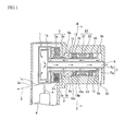
FIG. 1 is a sectional view of a structure of an X-ray generator according to an embodiment of the present invention; -
FIG. 2 is a sectional view in the direction of the arrow II-II inFIG. 1 ; -
FIG. 3 is a sectional view of a major portion of another embodiment of the present invention; -
FIG. 4 is a sectional view of a major portion of yet another embodiment of the present invention; and -
FIG. 5 is a sectional view of a structure of a conventional X-ray generator. - Embodiments of an X-ray generator according to the present invention will now be described with reference to drawings.
FIG. 1 is a sectional view of an X-ray generator according to an embodiment, andFIG. 2 is a sectional view in the direction of the arrow II-II inFIG. 1 . - The X-ray generator according to the present embodiment shown in
FIGS. 1 and2 differs from a conventional X-ray generator shown inFIG. 5 in the following three points. Since the other of the structure is the same as that of the X-ray generator shown inFIG. 5 , the same reference numeral is used to denote the same element, and further description thereof will be omitted. -
- (1) A
conductive fiber brush 20 having a large number ofconductive microfibers 22 serving as slide-contacting brush is arranged between a peripheral surface of ajournaling case part 2b of an anticathodeaccommodating case 2 and a peripheral surface of ashaft part 1b of arotary anticathode 1, such that current is flown from therotary anticathode 1 to theanticathode accommodating case 2 via theconductive fiber brush 20. - (2) An insulating
bearing 18 in which at least one of aninner ring 18a, anouter ring 18b or a rolling element (ball) 18c is made of an insulating material is used as a bearing for rotatively supporting theshaft part 1b of therotary anticathode 1. - (3) Pure water or ion-exchange water having low electric conductivity is used as cooling water flown through a water-cooled
jacket 7. - In this case, the insulating
bearing 18 is positioned in the axial direction by sleeve-shapedspacers shaft part 1b of therotary anticathode 1, and distal ends of theconductive microfibers 22 of theconductive fiber brush 20 are in contact with the outer periphery of the sleeve-shapedspacer 13. As shown inFIG. 2 , theconductive fiber brush 20 includes aconductive ring 21 and a large number of theconductive microfibers 22. Theconductive ring 21 is fitted into the inner periphery of thejournaling case part 2b. A base end of eachconductive microfiber 22 is supported by the inner periphery of theconductive ring 21 in a brush-like shape, and a distal end thereof is in soft contact with the outer periphery of thespacer 13. In other words, theconductive microfibers 22 are provided on the fixed side in the present embodiment. - Each
conductive microfiber 22 is conductive fine filament made by, for example, bonding several micron-sized ultra-microfiber made by carbonizing acrylic fiber with copper sulfide. The filament is longer than the clearance between the outer periphery of thespacer 13 and the inner periphery of theconductive ring 21. Therefore, when theshaft part 1b of therotary anticathode 1 and thespacer 13 are integrally rotated, the distal ends of theconductive microfibers 22, while being urged along the rotational direction of thespacer 13, slide with the outer periphery of thespacer 13 as if the distal ends were stroking the outer periphery. - A ceramic bearing in which ceramic balls are incorporated as the rolling element18 is preferably used as the insulating
bearing 20. - Such configuration as described above provides the following effects.
That is, theconductive fiber brush 20 having a large number of theconductive microfibers 22 serving as slide-contacting brush is arranged between the peripheral surface of thejournaling case part 2b and the peripheral surface of theshaft part 1b of therotary anticathode 1, with both peripheral surfaces being opposed to each other, such that current is flown from therotary anticathode 1 to theanticathode accommodating case 2 via theconductive fiber brush 20 of a conductive microfiber type. Accordingly, unlike the conventional case where a contact piece is made in slidable contact with the outer periphery of the shaft part by means of a force of a spring, the distal ends of theconductive microfibers 22 serving as slide-contacting brush can be in slidable contact with the outer periphery of thespacer 13 fitted into theshaft part 1b, in the state where substantially no pressure is applied thereto. Therefore, since no contact pressure is applied, theconductive microfibers 22 are free from wear, and current in therotary anticathode 1 can escape to theanticathode accommodating case 2 reliably over long periods. In addition, the insulatingbearing 18 is employed as the bearing for rotatively supporting therotary anticathode 1. Therefore, let alone a problem of electric corrosion of the bearing, a problem of decreased cooling efficiency caused by oxides generated in cooling water because of electric corrosion can be effectively resolved. - In addition, the
conductive microfibers 22 of theconductive fiber brush 20 are substantially free from wear, and there is no risk of temperature increase due to frictional heat. Therefore, theconductive microfibers 22 are compatible with the substantially increased rotational speed of therotary anticathode 1, thereby to enable increasing output and brightness of X-ray. Furthermore, there is neither risk of abrasion powders being generated from theconductive fiber brush 20, nor risk of temperature increase due to frictional heat. Therefore, such a problem that temperature increase or generation of abrasion powders would negatively affectseals bearing 18, or the like will not occur. In addition, substantially no frictional resistance is generated between the distal ends of theconductive microfibers 22 and thesleeve 13 on the outer periphery of theshaft part 1b. Therefore, rotational loss caused by theconductive fiber brush 20 can be eliminated, thereby to contribute to the size reduction of theelectric motor 3. - In addition, in the present embodiment, the
conductive fiber brush 20 includes theconductive ring 21 and a large number of theconductive microfibers 22. Theconductive ring 21 is fitted into the inner periphery of thejournaling case part 2b. The base end of eachconductive microfiber 22 is supported by the inner periphery of theconductive ring 21 in a brush-like shape, and the distal end thereof is in soft contact with the outer periphery of thespacer 13. Therefore, theconductive fiber brush 20 can be easily incorporated between therotary anticathode 1 and theanticathode accommodating case 2. - In addition, since pure water or ion-exchange water having low electric conductivity is used as cooling water flown through the water-cooled
jacket 7, it is possible to prevent oxides from being generated in the cooling water more reliably. Therefore, there is no risk of decreased cooling efficiency due to oxides, whereby stable performance can be assured. - Note that, the above-described embodiment has described the case where the
conductive microfibers 22 of theconductive fiber brush 20 are attached to theanticathode accommodating case 2 side, which is the fixed side. That is, it shows the case where theconductive fiber brush 20 includes: theconductive ring 21 fitted into the inner periphery of thejournaling case part 2b; and a large number of theconductive microfibers 22, with each base end thereof being supported by the inner periphery of theconductive ring 21 in a brush-like shape, and each distal end thereof being in soft contact with the outer periphery of theshaft part 1b of the rotary anticathode 1 (the outer periphery of the sleeve 13). Instead, like aconductive fiber brush 20B according to an embodiment inFIG. 3 , theconductive microfibers 22 may be attached to the rotation side. In this case, theconductive fiber brush 20B includes: theconductive ring 21 fitted into the outer periphery of theshaft part 1b of therotary anticathode 1; and a large number of theconductive microfibers 22, with each base end thereof being supported by the outer periphery of theconductive ring 21 in a brush-like shape, and each distal end thereof being in soft contact with the inner periphery of thejournaling case part 2b. - Alternatively, a
conductive fiber brush 20C shown inFIG. 4 may be employed. Theconductive fiber brush 20C includes a pair ofconductive rings conductive microfibers 22. Theconductive rings shaft part 1b of therotary anticathode 1 and on the inner periphery of thejournaling case part 2b, respectively. End surfaces of theconductive ring 21a and of theconductive ring 21b are opposed with other in the axial direction. A base end of eachconductive microfiber 22 is supported, in a brush-like shape, by the opposed end surface of oneconductive ring 21a of the pair ofconductive rings conductive ring 21b. Alternatively, theconductive microfibers 22 may be configured such that each base end thereof is attached to the opposed end surface of theconductive ring 21b on the fixed side, and each distal end thereof is in slidable contact with the opposed end surface of theconductive ring 21a on the rotation side. - Any configuration of the
conductive microfibers 22 is acceptable as long as the distal ends of a large number of theconductive microfibers 22, with the base ends thereof being fixed to the conductive ring, are in contact with the slidable contact surface of the counterpart side as if the base ends are stroking the contact surface.
Claims (6)
- An X-ray generator comprising:a rotary anticathode (1) having an anticathode part to generate an X-ray by
collision of thermal electrons, and a shaft part provided coaxially with the rotary anticathode part;an anticathode accommodating case (2) having an air-tight case for maintaining
a periphery of the anticathode part to a vacuum atmosphere, and a journaling case part (2b) for rotatably supporting the shaft part via a bearing (18);an electric motor (3) that rotatingly drives the rotary anticathode (1), anda cooled jacket (7) through which a cooling water is flown for cooling thewherein an insulating bearing (18) is used as the bearing (18), with at least
anticathode part and the shaft part (1 b), provided inside of the rotary anticathode,
either one of its inner ring (18a), outer ring (18b), and a rolling element (18c) being made of an insulating material,
wherein a conductive fiber brush (20) having a large number of conductive
microfibers (22) serving as slide-contacting brush, is arranged between the anticathode accommodating case (2) and the rotary anticathode (1), so that current is flown from the rotary anticathode (1) to the anticathode accommodating case (2) via the conductive fiber brush (20), and
wherein each of the conductive microfibers (22) of the conductive fiber brush (20) is a conductive fine filament made of a several micron-sized microfiber which is carbonized acrylic fiber with copper sulfide. - The X-ray generator according to claim 1, wherein
the conductive fiber brush (20) is arranged between opposing peripheral surfaces of the journaling case part (2b) of the anticathode accommodating case (2) and the shaft part (1 b) of the rotary anticathode (1). - The X-ray generator according to any one of the preceding claims, wherein the conductive fiber brush (20) comprises: a conductive ring fitted into an inner periphery of the journaling case part; and a large number of the conductive microfibers, each base end thereof being supported by an inner periphery of the conductive ring in a brush-like shape and each distal end thereof being in soft contact with an outer periphery of the shaft part (1 b) of the rotary anticathode (1).
- The X-ray generator according to any one of the preceding claims, wherein the conductive fiber brush (20) comprises: a conductive ring (21) fitted into an outer periphery of the shaft part (1 b) of the rotary anticathode (1); and a large number of the conductive microfibers (22), each base end thereof being supported by an outer periphery of the conductive ring (21) in a brush-like shape and each distal end thereof being in soft contact with an inner periphery of the journaling case part (2b).
- The X-ray generator according to any one of the preceding claims, wherein the conductive fiber brush (20) comprises: a pair of conductive rings (21 a, 21 b) which are provided respectively on an outer periphery of the shaft part (1 b) of the rotary anticathode (1) and on an inner periphery of the journaling case part (2b), with mutual end surfaces opposed to each other in the axial direction; and a large number of the conductive microfibers (22), each base end thereof being supported by an opposed end surface of one of the pair of conductive rings (21 a, 21 b) in a brush-like shape, and each distal end thereof being in soft contact with the opposed end surface of the other conductive ring.
- The use of an X-ray generator according to any one of the preceding claims, wherein pure water or ion-exchange water having low electric conductivity is used as cooling water flown through the water-cooled jacket (7).
Applications Claiming Priority (2)
| Application Number | Priority Date | Filing Date | Title |
|---|---|---|---|
| JP2007336450A JP2009158347A (en) | 2007-12-27 | 2007-12-27 | X-ray generator |
| EP08022497A EP2075820A3 (en) | 2007-12-27 | 2008-12-29 | X-ray tube |
Related Parent Applications (2)
| Application Number | Title | Priority Date | Filing Date |
|---|---|---|---|
| EP08022497A Division EP2075820A3 (en) | 2007-12-27 | 2008-12-29 | X-ray tube |
| EP08022497.5 Division | 2008-12-29 |
Publications (2)
| Publication Number | Publication Date |
|---|---|
| EP2492948A1 true EP2492948A1 (en) | 2012-08-29 |
| EP2492948B1 EP2492948B1 (en) | 2013-09-18 |
Family
ID=40481818
Family Applications (2)
| Application Number | Title | Priority Date | Filing Date |
|---|---|---|---|
| EP08022497A Withdrawn EP2075820A3 (en) | 2007-12-27 | 2008-12-29 | X-ray tube |
| EP12003029.1A Active EP2492948B1 (en) | 2007-12-27 | 2008-12-29 | X-ray generator |
Family Applications Before (1)
| Application Number | Title | Priority Date | Filing Date |
|---|---|---|---|
| EP08022497A Withdrawn EP2075820A3 (en) | 2007-12-27 | 2008-12-29 | X-ray tube |
Country Status (3)
| Country | Link |
|---|---|
| US (1) | US8243885B2 (en) |
| EP (2) | EP2075820A3 (en) |
| JP (1) | JP2009158347A (en) |
Families Citing this family (8)
| Publication number | Priority date | Publication date | Assignee | Title |
|---|---|---|---|---|
| JP5113813B2 (en) * | 2009-09-01 | 2013-01-09 | ブルカー・エイエックスエス株式会社 | X-ray generator |
| JP5238646B2 (en) * | 2009-09-01 | 2013-07-17 | ブルカー・エイエックスエス株式会社 | X-ray generator |
| US9685843B2 (en) | 2013-03-14 | 2017-06-20 | Regal Beloit America, Inc. | Grounding device for electric machine and methods of assembling the same |
| DE102013113562B4 (en) * | 2013-12-05 | 2018-10-04 | VON ARDENNE Asset GmbH & Co. KG | Bearing assembly for rotatably supporting an electrode and electrode assembly |
| EP3086448B1 (en) * | 2015-04-22 | 2022-08-03 | Regal Beloit America, Inc. | Grounding device for electric machine and methods of assembling the same |
| AU2017286618B2 (en) | 2016-06-17 | 2022-03-17 | The Institute Of Cancer Research: Royal Cancer Hospital | X-ray micro-beam production and high brilliance x-ray production |
| CN109838794A (en) * | 2019-02-28 | 2019-06-04 | 北京航化节能环保技术有限公司 | A kind of water-cooling jacket incinerator and method handling salt bearing liquid wastes and exhaust gas |
| KR102314718B1 (en) * | 2019-11-07 | 2021-10-18 | 현대트랜시스 주식회사 | Device for preventing electrical erosion of bearing |
Citations (5)
| Publication number | Priority date | Publication date | Assignee | Title |
|---|---|---|---|---|
| EP0487046A2 (en) * | 1990-11-21 | 1992-05-27 | Canon Kabushiki Kaisha | Image forming apparatus |
| JPH07192665A (en) | 1993-12-27 | 1995-07-28 | Mac Sci:Kk | X-ray generating device |
| JPH08106870A (en) | 1994-09-30 | 1996-04-23 | Rigaku Corp | Rotating pair cathode assembly of x-ray tube |
| US20050280329A1 (en) * | 2004-06-18 | 2005-12-22 | Day Michael J | Electrical contact technology and methodology for the manufacture of large-diameter electrical slip rings |
| US20060013364A1 (en) * | 2004-07-15 | 2006-01-19 | Rigaku Corporation | Rotating anode X-ray tube and X-ray generator |
Family Cites Families (12)
| Publication number | Priority date | Publication date | Assignee | Title |
|---|---|---|---|---|
| JPH05249846A (en) * | 1992-03-05 | 1993-09-28 | Canon Inc | Image forming device |
| DE69317960T2 (en) * | 1992-08-28 | 1998-10-08 | Canon Kk | Imaging device for creating images on both sides of a recording material |
| JPH11219677A (en) * | 1998-01-30 | 1999-08-10 | Rigaku Denki Kk | Cooling water circulating device for x-ray generating device |
| JP2000353485A (en) * | 1999-06-11 | 2000-12-19 | Toshiba Corp | Rotating anode x-ray tube device and its manufacture |
| US6519317B2 (en) * | 2001-04-09 | 2003-02-11 | Varian Medical Systems, Inc. | Dual fluid cooling system for high power x-ray tubes |
| US7193836B2 (en) * | 2003-03-17 | 2007-03-20 | Illinois Tool Works Inc | Grounding brush for mitigating electrical current on motor shafts |
| US7136271B2 (en) * | 2003-03-17 | 2006-11-14 | Illinois Tool Works Inc | Static charge neutralizing assembly for use on rollers and shafts |
| JP3898684B2 (en) * | 2003-10-17 | 2007-03-28 | 株式会社リガク | Rotating current collector and rotating cathode X-ray tube |
| US20070278093A1 (en) * | 2006-06-02 | 2007-12-06 | Barnard Michael P | Electrical conductive contact ring for electroplating or electrodeposition |
| CN200941706Y (en) * | 2006-08-18 | 2007-08-29 | 江西铜业股份有限公司永平铜矿 | X-ray tube constant temp controller of fluorescent on-line analyzer |
| US8189317B2 (en) * | 2007-04-23 | 2012-05-29 | Illinois Tool Works Inc. | Grounding brush system for mitigating electrical current on rotating shafts |
| US20090045694A1 (en) * | 2007-08-15 | 2009-02-19 | Oh Hieyoung W | Microfiber high current conduction device |
-
2007
- 2007-12-27 JP JP2007336450A patent/JP2009158347A/en active Pending
-
2008
- 2008-12-29 US US12/318,413 patent/US8243885B2/en not_active Expired - Fee Related
- 2008-12-29 EP EP08022497A patent/EP2075820A3/en not_active Withdrawn
- 2008-12-29 EP EP12003029.1A patent/EP2492948B1/en active Active
Patent Citations (5)
| Publication number | Priority date | Publication date | Assignee | Title |
|---|---|---|---|---|
| EP0487046A2 (en) * | 1990-11-21 | 1992-05-27 | Canon Kabushiki Kaisha | Image forming apparatus |
| JPH07192665A (en) | 1993-12-27 | 1995-07-28 | Mac Sci:Kk | X-ray generating device |
| JPH08106870A (en) | 1994-09-30 | 1996-04-23 | Rigaku Corp | Rotating pair cathode assembly of x-ray tube |
| US20050280329A1 (en) * | 2004-06-18 | 2005-12-22 | Day Michael J | Electrical contact technology and methodology for the manufacture of large-diameter electrical slip rings |
| US20060013364A1 (en) * | 2004-07-15 | 2006-01-19 | Rigaku Corporation | Rotating anode X-ray tube and X-ray generator |
Also Published As
| Publication number | Publication date |
|---|---|
| JP2009158347A (en) | 2009-07-16 |
| EP2075820A3 (en) | 2009-09-30 |
| US8243885B2 (en) | 2012-08-14 |
| EP2075820A2 (en) | 2009-07-01 |
| US20090175420A1 (en) | 2009-07-09 |
| EP2492948B1 (en) | 2013-09-18 |
Similar Documents
| Publication | Publication Date | Title |
|---|---|---|
| US8243885B2 (en) | X-ray generator | |
| JP4899858B2 (en) | Envelope rotating X-ray tube device | |
| JP5259406B2 (en) | Rotating anode X-ray tube | |
| US7558376B2 (en) | Rotating anode X-ray tube assembly | |
| JPH11224627A (en) | Straddle bearing assembly | |
| US4413356A (en) | Flat rotary-anode X-ray tube | |
| EP1241701A1 (en) | Rotary anode type x-ray tube | |
| US6377658B1 (en) | Seal for liquid metal bearing assembly | |
| KR101824135B1 (en) | Thermal damage preventing rotating anode type X-ray tube | |
| US6456693B1 (en) | Multiple row spiral groove bearing for X-ray tube | |
| US20060256923A1 (en) | Device for generating x-rays | |
| CA2709921A1 (en) | Pivoting high flux x-ray target and assembly | |
| US9275822B2 (en) | Liquid metal containment in an X-ray tube | |
| JP2019030192A (en) | Electric motor and heat sink device using the same | |
| JP2010277822A (en) | X-ray tube device | |
| CN209766355U (en) | Novel X-ray CT tube | |
| KR20180066686A (en) | Plain bearing, and rotating anode type X-ray tube | |
| WO2016121693A1 (en) | Rotating anode x-ray tube | |
| WO2002091815A2 (en) | Low thermal resistance bearing assembly for x-ray device | |
| US10158269B1 (en) | Electric motor and heat sink apparatus using the same | |
| JP5138782B2 (en) | Movable high flux X-ray target and assembly | |
| CN117316742B (en) | X-ray tube | |
| CN214505434U (en) | X-ray generating device and imaging equipment | |
| JP2020021647A (en) | Rotary anode x-ray tube | |
| US6947524B2 (en) | Target bore strengthening method |
Legal Events
| Date | Code | Title | Description |
|---|---|---|---|
| PUAI | Public reference made under article 153(3) epc to a published international application that has entered the european phase |
Free format text: ORIGINAL CODE: 0009012 |
|
| AC | Divisional application: reference to earlier application |
Ref document number: 2075820 Country of ref document: EP Kind code of ref document: P |
|
| AK | Designated contracting states |
Kind code of ref document: A1 Designated state(s): DE NL |
|
| 17P | Request for examination filed |
Effective date: 20130227 |
|
| RIC1 | Information provided on ipc code assigned before grant |
Ipc: H01J 35/26 20060101AFI20130318BHEP |
|
| GRAP | Despatch of communication of intention to grant a patent |
Free format text: ORIGINAL CODE: EPIDOSNIGR1 |
|
| INTG | Intention to grant announced |
Effective date: 20130426 |
|
| GRAS | Grant fee paid |
Free format text: ORIGINAL CODE: EPIDOSNIGR3 |
|
| GRAA | (expected) grant |
Free format text: ORIGINAL CODE: 0009210 |
|
| AC | Divisional application: reference to earlier application |
Ref document number: 2075820 Country of ref document: EP Kind code of ref document: P |
|
| AK | Designated contracting states |
Kind code of ref document: B1 Designated state(s): DE NL |
|
| REG | Reference to a national code |
Ref country code: DE Ref legal event code: R096 Ref document number: 602008027729 Country of ref document: DE Effective date: 20131114 |
|
| REG | Reference to a national code |
Ref country code: NL Ref legal event code: T3 |
|
| REG | Reference to a national code |
Ref country code: DE Ref legal event code: R097 Ref document number: 602008027729 Country of ref document: DE |
|
| PLBE | No opposition filed within time limit |
Free format text: ORIGINAL CODE: 0009261 |
|
| STAA | Information on the status of an ep patent application or granted ep patent |
Free format text: STATUS: NO OPPOSITION FILED WITHIN TIME LIMIT |
|
| 26N | No opposition filed |
Effective date: 20140619 |
|
| REG | Reference to a national code |
Ref country code: DE Ref legal event code: R097 Ref document number: 602008027729 Country of ref document: DE Effective date: 20140619 |
|
| PGFP | Annual fee paid to national office [announced via postgrant information from national office to epo] |
Ref country code: NL Payment date: 20171219 Year of fee payment: 10 |
|
| REG | Reference to a national code |
Ref country code: DE Ref legal event code: R082 Ref document number: 602008027729 Country of ref document: DE Representative=s name: MUELLER-BORE & PARTNER PATENTANWAELTE PARTG MB, DE Ref country code: DE Ref legal event code: R081 Ref document number: 602008027729 Country of ref document: DE Owner name: BRUKER JAPAN KABUSHIKI KAISHA, YOKOHAMA-SHI, JP Free format text: FORMER OWNER: BRUKER AXS KABUSHIKI KAISHA, YOKOHAMA-SHI, KANAGAWA, JP |
|
| REG | Reference to a national code |
Ref country code: NL Ref legal event code: PD Owner name: BRUKER JAPAN K. K.; JP Free format text: DETAILS ASSIGNMENT: CHANGE OF OWNER(S), MERGE; FORMER OWNER NAME: BRUKER AXS KABUSHIKI KAISHA Effective date: 20180228 |
|
| REG | Reference to a national code |
Ref country code: NL Ref legal event code: MM Effective date: 20190101 |
|
| PG25 | Lapsed in a contracting state [announced via postgrant information from national office to epo] |
Ref country code: NL Free format text: LAPSE BECAUSE OF NON-PAYMENT OF DUE FEES Effective date: 20190101 |
|
| PGFP | Annual fee paid to national office [announced via postgrant information from national office to epo] |
Ref country code: DE Payment date: 20221221 Year of fee payment: 15 |