JP5113813B2 - X-ray generator - Google Patents
X-ray generator Download PDFInfo
- Publication number
- JP5113813B2 JP5113813B2 JP2009202110A JP2009202110A JP5113813B2 JP 5113813 B2 JP5113813 B2 JP 5113813B2 JP 2009202110 A JP2009202110 A JP 2009202110A JP 2009202110 A JP2009202110 A JP 2009202110A JP 5113813 B2 JP5113813 B2 JP 5113813B2
- Authority
- JP
- Japan
- Prior art keywords
- refrigerant
- housing
- seal
- cathode
- shaft portion
- Prior art date
- Legal status (The legal status is an assumption and is not a legal conclusion. Google has not performed a legal analysis and makes no representation as to the accuracy of the status listed.)
- Active
Links
Images


Description
本発明は、回転対陰極型のX線発生装置に関するものである。 The present invention relates to a rotating counter cathode type X-ray generator.
図11は従来の回転対陰極型のX線発生装置の一例を示す側断面図、図12はその外観を一部を分解して示す斜視図である。
このX線発生装置は、例えば、特許文献1などにおいて知られているX線発生装置と類似のものである。
FIG. 11 is a side sectional view showing an example of a conventional rotating cathode type X-ray generator, and FIG. 12 is a perspective view showing a part of the appearance thereof.
This X-ray generator is similar to the X-ray generator known in
図11に示すように、このX線発生装置は、回転対陰極301と、それを回転自在に支持するハウジング310、320とを有している。ハウジングは、軸方向の一端である前端側(図中左端側)が真空ケース内Aに臨み、軸方向の他端である後端側(図中右端側)が真空ケース外Bに臨むように真空ケースのケース壁500に取り付けられるもので、前側ハウジング310と後側ハウジング320に二分割されており、前側ハウジング310に設けたフランジ311により、真空ケースのケース壁500に取り付けられるようになっている。前側ハウジング310及び後側ハウジング320には、軸方向に沿って貫通孔313、323が形成されており、前側ハウジング310の貫通孔313の内周には、該貫通孔313の内周に嵌合された円筒状スリーブ部材314を介して、前後方向に相互に離間して前側軸受306と後側軸受307が装備されている。
As shown in FIG. 11, the X-ray generator includes a rotating anti-cathode 301 and
回転対陰極301は、貫通孔313、323内に挿入されて前側軸受306及び後側軸受307により回転自在に支持された中空軸部303と、その中空軸部303の前端部に一体に設けられ、前記真空ケース内Aに挿入されて、外周の対陰極面302aに熱電子の照射を受けることによりX線を発生する円筒型の対陰極部302とを有するものである。
The rotating anti-cathode 301 is integrally provided at the front end portion of the
この回転対陰極301の対陰極部302と前側ハウジング310の前端部との間には、回転対陰極301を回転駆動するための電動機304が配設されており、対陰極部302側に永久磁石からなるロータ304aが設けられ、前側ハウジング310の前端部側に、ロータ304aに回転力を与えるためのコイル304bが設けられている。
An
また、回転対陰極301の内部には、対陰極部302と中空軸部303とを冷却するための冷媒を流通させる冷媒流路が設けられており、その冷媒通路は、回転対陰極301の内部に同心状に挿入されたセパレータ部材360により、往路と復路の2つの流路に仕切られている。往路は、最も高温化する対陰極部302に冷媒を流入させる流入側通路370の一部を構成する部分、復路は、対陰極部302の冷媒を外部に向けて流出させる流出側通路380の一部を構成する部分である。
In addition, inside the rotating
セパレータ部材360は、対陰極部302の内部を効率良く冷媒が流れるように2つの流路空間に仕切るディスク状部361を前端に有し、その後側に、ディスク状部361の中心部から後方に垂直に延びる管状軸部362を有するものであり、管状軸部362の後端が後側ハウジング320の後端部に固定されることで、回転対陰極301の内部に支持されている。そして、セパレータ部材360の管状軸部362は、回転対陰極301の中空軸部303の内部に同心状に挿入されていることで、中空軸部303の内部の冷媒流路を、管状軸部362の内側の流路と外側の流路とに仕切っている。ここでは、例えば管状軸部362の外側の流路が往路として設定され、管状流路362の外側の流路が復路として設定されている。
また、後側ハウジング320には、外部の冷媒供給管に接続されることで、中空軸部303内の往路に向けて冷媒を流入させる冷媒流入口370A(図12参照)と、外部の冷媒排出管に接続されることで、中空軸部303内の復路からの冷媒を外部に排出する冷媒流出口380A(図12参照)とが設けられている。これらの冷媒流入口370A及び冷媒排出口380Aは、前側ハウジング310内及び後側ハウジング320内に形成された内部流路327、328を介して、前記中空軸部303内の往路及び復路にそれぞれ接続されている。
Further, the
また、貫通孔313、323と回転対陰極301の中空軸部303の間の空間のうち、前側軸受306よりも真空ケース内A側に位置する箇所には、前側ハウジング310と回転対陰極301の間の隙間を気密シールする真空シール305が配設されている。真空シールとしては、磁気シールが設けられている。
Further, in the space between the through-
また、貫通孔313、323と回転対陰極301の中空軸部303の間の空間のうち、後側軸受307よりも真空ケース外B側に位置する箇所には、後側ハウジング320と回転対陰極301の中空軸部303との間の隙間を液密シールする冷媒シール350が配設されている。
Further, in the space between the through-
また、この種の回転対陰極型X線発生装置においては、運転中に回転対陰極301に電子ビームの形で電流(管電流と呼ばれる)が流れるので、回転している回転対陰極301から固定側のハウジング310、320へと電流を逃がす必要がある。この場合、回転対陰極301からハウジング310に鋼製の軸受を経由して電流を流すと、軸受を構成している転動体(例えば鋼球)と内外輪(軌道輪)との接触部に電食現象が発生して故障の原因となる。
Further, in this type of rotating counter-cathode X-ray generator, a current (referred to as tube current) flows in the form of an electron beam through the rotating
そこで、この電食現象を防止するために、回転部と固定部との間に導電ブラシを配置し、導電ブラシを経由して回転部から固定部へ電流が流れるようにしている。例えば、この従来のX線発生装置では、前側軸受306と後側軸受307の間に導電ブラシ340を配置し、導電ブラシ340の摺動面(内周面)を、回転対陰極301の中空軸部303の外周に直接または導電性スペーサ等を介して間接的に摺動接触させることにより、導電ブラシ340を経由して、回転対陰極301からハウジング310、320に電流を逃がすようにしている。
Therefore, in order to prevent this electrolytic corrosion phenomenon, a conductive brush is disposed between the rotating part and the fixed part so that a current flows from the rotating part to the fixed part via the conductive brush. For example, in this conventional X-ray generator, the
ところで、摺動部材である冷媒シール350は、摩耗が進んだ場合に適当なタイミングでの交換が必要となるが、従来のX線発生装置においては、図12に示すように、後側ハウジング320を外した上でないと、冷媒シール350を交換することができなかった。また、後側ハウジング320をばらすには、冷媒の配管類も取り外す必要があるうえ、光学系の調整も後から必要になることがあるため、交換が非常に面倒であった。
By the way, the
本発明は、上記事情を考慮し、ハウジングを全くばらさずに簡単に冷媒シールの交換を行うことができるようにしたX線発生装置を提供することを目的とする。 In view of the above circumstances, an object of the present invention is to provide an X-ray generator capable of easily replacing a refrigerant seal without separating the housing.
本発明の上記課題は、以下の構成によって達成される。
(1) 軸方向の一端である前端側が真空ケース内に臨み、軸方向の他端である後端側が真空ケース外に臨むように取り付けられるハウジングと、
該ハウジングに軸方向に沿って形成された貫通孔と、
該貫通孔の内周に装備された軸受と、
前記貫通孔内に挿入され前記軸受によって回転自在に支持された中空軸部を有すると共に、該中空軸部の前端部に、前記真空ケース内に挿入されて熱電子の照射を受けることによりX線を発生する対陰極部が一体に設けられた回転対陰極と、
該回転対陰極を回転駆動する電動機と、
前記回転対陰極の内部に形成され、前記対陰極部と中空軸部とを冷却するための冷媒を流通させる冷媒流路と、
前記回転対陰極の少なくとも中空軸部の内部に同心状に挿入されて、前記冷媒流路を往路と復路に仕切るセパレータ部材と、
前記ハウジングに形成され、外部の冷媒供給管に接続されることで、前記往路に冷媒を流入させる冷媒流入口と、
前記ハウジングに形成され、外部の冷媒排出管に接続されることで、前記復路からの冷媒を外部に排出する冷媒流出口と、
前記貫通孔と回転対陰極の中空軸部の間の空間のうち、前記軸受よりも真空ケース内側に位置する箇所に配設されて、前記ハウジングと回転対陰極の間の隙間をシールする真空シールと、
前記貫通孔と回転対陰極の中空軸部の間の空間のうち、前記軸受よりも真空ケース外側に位置する箇所に配設されて、前記ハウジングと回転対陰極の間の隙間をシールする冷媒シールと、
を有するX線発生装置において、
前記ハウジングの貫通孔の後端にシールキャップが着脱可能に液密状態で嵌合されており、そのシールキャップに前記冷媒シールが取り付けられると共に、該シールキャップに、前記ハウジングに形成された冷媒流入口を前記往路に連通させる流入側連通路と、前記ハウジングに形成された冷媒流出口を前記復路に連通させる流出側連通路とが設けられていることを特徴とするX線発生装置。
(2) 上記(1)の構成において、
前記シールキャップの軸方向の前部に、前記冷媒シールの外周を着脱自在に嵌合するシール嵌合孔が設けられ、そのシール嵌合孔より軸方向の後側に、前記流入側連通路と流出側連通路とが互いに流路を分けて設けられていることを特徴とする請求項1に記載のX線発生装置。
(3) 上記(2)の構成において、
前記セパレータ部材は、
後端が前記シールキャップに固定されて前記回転対陰極の中空軸部の内部に同心状に挿入されることで、前記中空軸部の内部の前記冷媒流路を、前記管状軸部の内側の流路と外側の流路とに仕切り、前記内側の流路及び外側の流路のいずれか一方を前記往路とし他方を前記復路とする管状軸部を有しており、
前記シールキャップのシール嵌合孔より軸方向の後側に、前記管状軸部の外周の嵌まる軸部嵌合孔が設けられ、
前記軸部嵌合孔の内壁面に、前記流入側連通路と流出側連通路のうちの一方の開口が設けられ、
前記軸部嵌合孔と前記シール嵌合孔に嵌合される冷媒シールとの間に位置するシールキャップの内壁面に、前記流入側連通路と流出側連通路のうちの他方の開口が設けられていることを特徴とする請求項2に記載のX線発生装置。
(4) 上記(1)〜(3)のいずれかの構成において、
前記電動機が、前記ハウジングの前端部と前記対陰極部との間に配設されており、対陰極部側にロータが設けられ、前記ハウジングの前端部側に、前記ロータを回転させるためのコイルが設けられていることを特徴とする請求項1〜3のいずれか1項に記載のX線発
生装置。
The above object of the present invention is achieved by the following configurations.
(1) a housing attached so that a front end side which is one end in the axial direction faces the inside of the vacuum case and a rear end side which is the other end in the axial direction faces the outside of the vacuum case;
A through hole formed in the housing along the axial direction;
A bearing provided on the inner periphery of the through hole;
The hollow shaft portion is inserted into the through hole and is rotatably supported by the bearing, and the front end portion of the hollow shaft portion is inserted into the vacuum case and irradiated with thermionic electrons to receive X-rays. A rotating counter cathode provided integrally with a counter cathode portion for generating
An electric motor for rotationally driving the rotating anti-cathode;
A refrigerant flow path formed inside the rotating counter cathode and through which a refrigerant for cooling the counter cathode portion and the hollow shaft portion flows;
A separator member that is concentrically inserted into at least the hollow shaft portion of the rotating counter-cathode and partitions the refrigerant flow path into a forward path and a return path;
Formed in the housing and connected to an external refrigerant supply pipe, whereby a refrigerant inlet for allowing the refrigerant to flow into the forward path;
A refrigerant outlet that is formed in the housing and connected to an external refrigerant discharge pipe to discharge the refrigerant from the return path to the outside;
A vacuum seal that seals a gap between the housing and the rotating counter-cathode, which is disposed in a space between the through hole and the hollow shaft portion of the rotating counter-cathode and located inside the vacuum case with respect to the bearing. When,
A refrigerant seal that is disposed in a space between the through hole and the hollow shaft portion of the rotating anti-cathode and located outside the vacuum case with respect to the bearing, and seals a gap between the housing and the rotating anti-cathode. When,
In an X-ray generator having
A seal cap is detachably fitted to the rear end of the through hole of the housing, and the refrigerant seal is attached to the seal cap, and a refrigerant flow formed in the housing is attached to the seal cap. An X-ray generating apparatus, comprising: an inflow side communication path that communicates an inlet with the forward path; and an outflow side communication path that communicates a refrigerant outlet formed in the housing with the return path.
(2) In the configuration of (1) above,
A seal fitting hole for detachably fitting the outer periphery of the refrigerant seal is provided in the axial front portion of the seal cap, and the inflow side communication path is provided on the rear side in the axial direction from the seal fitting hole. The X-ray generator according to
(3) In the configuration of (2) above,
The separator member is
A rear end is fixed to the seal cap and is inserted concentrically into the hollow shaft portion of the rotating anti-cathode, so that the refrigerant flow path inside the hollow shaft portion is placed inside the tubular shaft portion. Partitioning into a flow path and an outer flow path, and having a tubular shaft portion with one of the inner flow path and the outer flow path as the forward path and the other as the return path,
On the rear side in the axial direction from the seal fitting hole of the seal cap, there is provided a shaft fitting hole on which the outer periphery of the tubular shaft is fitted,
One opening of the inflow side communication path and the outflow side communication path is provided on the inner wall surface of the shaft portion fitting hole,
The other opening of the inflow side communication path and the outflow side communication path is provided on the inner wall surface of the seal cap positioned between the shaft portion fitting hole and the refrigerant seal fitted in the seal fitting hole. The X-ray generator according to
(4) In any one of the constitutions (1) to (3),
The electric motor is disposed between a front end portion of the housing and the counter cathode portion, a rotor is provided on the counter cathode portion side, and a coil for rotating the rotor on the front end portion side of the housing The X-ray generator according to
本発明は、次の効果を奏する。
(1)の構成によれば、ハウジングの貫通孔の後端にシールキャップを着脱自在に嵌合させ、そのシールキャップに冷媒シールを取り付けているので、真空ケースの真空状態を保持したまま、また、ハウジングに形成してある冷媒流入口と冷媒流出口に外部の冷媒供給管や冷媒排出管を接続した状態のまま、冷媒シールを交換することができる。しかも、ハウジング自体はばらさないでよいので、簡単に且つ光学系への影響を及ぼさずに冷媒シールの交換を行うことができる。また、シールキャップに流入側連通路及び流出側連通路を設けることにより、冷媒の流路(往路と復路)の振り分け機能を持たせているので、流路の複雑な構成をシールキャップに集約することができ、他の部品の構造のシンプル化が図れる。
(2)の構成によれば、シールキャップに着脱自在に冷媒シールを嵌合させているので、シールキャップをハウジングから取り外すことで、冷媒シールだけを簡単に交換することができる。
(3)の構成によれば、シールキャップのシール嵌合孔に冷媒シールを嵌合させ、シールキャップの軸部嵌合孔にセパレータ部材の管状軸部を嵌合させることより、冷媒流路の往路と復路を構成する管状軸部の内側の流路と外側の流路に、シールキャップ内のそれぞれの連通路を容易に連通させることができ、組み付けの容易化が図れる。
(4)の構成によれば、ハウジングの前端部に電動機が設けられているので、ハウジングの後部の構成を単純化することができ、シールキャップの取付条件を楽に設定することができる。
The present invention has the following effects.
According to the configuration of (1), the seal cap is detachably fitted to the rear end of the through hole of the housing, and the refrigerant seal is attached to the seal cap, so that the vacuum state of the vacuum case is maintained. The refrigerant seal can be exchanged while the external refrigerant supply pipe and the refrigerant discharge pipe are connected to the refrigerant inlet and the refrigerant outlet formed in the housing. In addition, since the housing itself does not need to be separated, the refrigerant seal can be replaced easily and without affecting the optical system. In addition, since the inflow side communication path and the outflow side communication path are provided in the seal cap, the refrigerant flow path (forward path and return path) distribution function is provided, so the complicated configuration of the flow path is concentrated in the seal cap. It is possible to simplify the structure of other parts.
According to the configuration of (2), since the refrigerant seal is detachably fitted to the seal cap, only the refrigerant seal can be easily replaced by removing the seal cap from the housing.
According to the configuration of (3), the refrigerant seal is fitted into the seal fitting hole of the seal cap, and the tubular shaft part of the separator member is fitted into the shaft part fitting hole of the seal cap. The respective communication paths in the seal cap can be easily communicated with the flow path on the inner side and the outer flow path of the tubular shaft portion constituting the forward path and the return path, and assembling can be facilitated.
According to the structure of (4), since the electric motor is provided in the front-end part of the housing, the structure of the rear part of a housing can be simplified and the attachment conditions of a seal cap can be set easily.
以下、本発明の実施形態のX線発生装置を説明する。
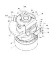
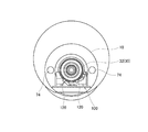
図1〜図10は本発明の実施形態のX線発生装置の説明図で、図1は同X線発生装置の一部を分解して示す斜視図、図2は同X線発生装置の他の一部を分解して示す斜視図、図3は同X線発生装置の軸方向後側から見た正面図、図4は図3のIV−IV矢視断面図、図5は図3のV−V矢視断面図、図6は図5のVI−VI矢視断面図、図7(a)は図3のVIIa−VIIaの矢視断面図、(b)は(a)のVIIb−VIIbの矢視断面図
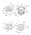
、図8は同X線発生装置の導電ブラシカセットの構成図で、(a)は斜視図、(b)は別の角度から見た斜視図、(c)は断面図、(d)はカセット取付状態における導電ブラシの形態を示す図、図9は同X線発生装置のシールキャップの構成図で、(a)は斜視図、(b)は別の角度から見た斜視図、(c)は(a)のIXc−IXc矢視断面図、(d)は(c)のIXc−IXc矢視断面図、図10は同X線発生装置の原理構成を示す断面図である。
Hereinafter, an X-ray generator according to an embodiment of the present invention will be described.
1 to 10 are explanatory diagrams of an X-ray generator according to an embodiment of the present invention. FIG. 1 is an exploded perspective view showing a part of the X-ray generator. FIG. FIG. 3 is a front view of the X-ray generator as viewed from the rear side in the axial direction, FIG. 4 is a sectional view taken along the line IV-IV in FIG. 3, and FIG. 6 is a sectional view taken along the line VI-VI in FIG. 5, FIG. 7A is a sectional view taken along the line VIIa-VIIa in FIG. 3, and FIG. 6B is a sectional view taken along the line VIIb- in FIG. FIG. 8 is a configuration diagram of a conductive brush cassette of the X-ray generator, (a) is a perspective view, (b) is a perspective view seen from another angle, and (c) is a sectional view. FIGS. 9A and 9D are views showing the shape of the conductive brush in the cassette mounting state, FIG. 9 is a configuration diagram of the seal cap of the X-ray generator, FIG. 9A is a perspective view, and FIG. 9B is seen from another angle. Perspective , (C) is a sectional view taken along arrow IXc-IXc in (a), (d) is a sectional view taken along arrow IXc-IXc in (c), and FIG. 10 is a sectional view showing the basic configuration of the X-ray generator. .
ここでは、図1〜図9に示す具体的な構成のX線発生装置の説明に先だって、理解を容易にするために、図10を参照しながら実施形態のX線発生装置の原理構成について説明する。なお、図10中の( )内の符号は、図1〜図9において示す具体的な要素(後述)と対応していることを示している。 Here, prior to the description of the X-ray generator having the specific configuration shown in FIGS. 1 to 9, the principle configuration of the X-ray generator of the embodiment will be described with reference to FIG. 10 in order to facilitate understanding. To do. In addition, the code | symbol in () in FIG. 10 has shown corresponding with the concrete element (after-mentioned) shown in FIGS.
図10に示すように、このX線発生装置Mは、軸方向の一端である前端側(F)が真空ケース内Aに臨み、軸方向の他端である後端側(B)が真空ケース外Bに臨むように取り付けられるハウジング1000と、ハウジング1000に軸方向に沿って形成された貫通孔1002と、この貫通孔1002の内周に装備された軸受1004と、前記貫通孔1002内に挿入され、軸受1004によって回転自在に支持された中空軸部1006を有すると共に、中空軸部1006の前端部に、真空ケース内Aに挿入されて熱電子の照射を受けることによりX線を発生する対陰極部1008が一体に設けられた回転対陰極1010と、回転対陰極1010を回転駆動する電動機(図示略)と、回転対陰極1010の内部に形成され、対陰極部1010と中空軸部1006とを冷却するための冷媒を流通させる冷媒流路1012と、回転対陰極1010の少なくとも中空軸部1006の内部に同心状に挿入されて、冷媒流路1012を往路1014と復路1016に仕切るセパレータ部材1018と、ハウジング1000に形成され、外部の冷媒供給管に接続されることで、往路1014に冷媒を流入させる冷媒流入口1020と、ハウジング1000に形成され、外部の冷媒排出管に接続されることで、復路1016からの冷媒を外部に排出する冷媒流出口1022と、ハウジング1000内の貫通孔1002と回転対陰極1010の中空軸部1006の間の空間のうち、軸受1004よりも真空ケース内A側に位置する箇所に配設されて、ハウジング1000と回転対陰極1010の間の隙間をシールする真空シール1024と、貫通孔1002と回転対陰極1010の中空軸部1006の間の空間のうち、軸受1004よりも真空ケース外B側に位置する箇所に配設されて、ハウジング1000と回転対陰極1010の間の隙間をシールする冷媒シール1026と、回転対陰極1010の外周に摺動接触することで、回転対陰極1010からハウジング1000に電流を逃がす導電ブラシ1028と、を有している。
As shown in FIG. 10, the X-ray generator M has a front end side (F) that is one end in the axial direction facing the inside A of the vacuum case, and a rear end side (B) that is the other end in the axial direction. A housing 1000 mounted so as to face the outer side B, a through hole 1002 formed in the housing 1000 along the axial direction, a
この場合、本実施形態の第1の特徴的な点として、ハウジング1000の胴部には、ハウジング1000の外表面から貫通孔1002の内部に臨むブラシ取付窓1030が設けられており、そのブラシ取付窓1030に、複数の導電ブラシ1028を一体に具備した導電ブラシカセット1032が着脱自在に装着されている。
In this case, as a first characteristic point of the present embodiment, the body portion of the housing 1000 is provided with a
また、第2の特徴的な点として、ハウジング1000の貫通孔1002の後端にはシールキャップ1036が着脱可能に液密状態で嵌合されており、そのシールキャップ1036に冷媒シール1026が取り付けられると共に、シールキャップ1036に、ハウジング1000に形成された冷媒流入口1020を往路1014に連通させる流入側連通路1038と、ハウジング1000に形成された冷媒流出口1022を復路1016に連通させる流出側連通路1040とが設けられている。
Further, as a second characteristic point, a
次に、そのような原理構成を盛り込んだ具体的な構成のX線発生装置Mの詳細について図1〜図9を参照しながら説明する。 Next, details of the X-ray generator M having a specific configuration incorporating such a principle configuration will be described with reference to FIGS.
このX線発生装置Mは、回転対陰極1と、それを回転自在に支持するハウジング10、20とを有している。ハウジングは、軸方向の一端である前端側(図中左端側)が真空ケース内Aに臨み、軸方向の他端である後端側(図中右端側)が真空ケース外Bに臨むように真空ケースのケース壁500に取り付けられるもので、前側ハウジング10と後側ハウジング20に二分割されており、前側ハウジング10に設けたフランジ11により、真空ケースのケース壁500に取り付けられるようになっている。
The X-ray generator M includes a
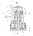
図4に示すように、前側ハウジング10及び後側ハウジング20には、それぞれ軸方向に沿って貫通孔13、23が形成されており、前側ハウジング10の貫通孔13の内周には、該貫通孔13の内周に嵌合された円筒状スリーブ部材14を介して、前後方向に相互に離間して前側軸受6と後側軸受7が装備されている。円筒状スリーブ部材14を介在させる理由は、円筒状スリーブ部材14の外周面と前側ハウジング10の貫通孔13の内周面との間に、冷媒の流れる環状流路73(後述)を確保するためである。
As shown in FIG. 4, through
また、前側軸受6及び後側軸受7としては、例えば、内輪と外輪と転動体の少なくともいずれかの部品が絶縁材料(セラミック等)で構成された絶縁ベアリングが使用されている。なお、前側軸受6と後側軸受7の間には、それらの相互間隔を保つための外周側及び内周側の各スペーサ8、9が配置されている。
In addition, as the
前側ハウジング10と後側ハウジング20は、前側ハウジング10の後端の合わせ面15と後側ハウジング20の前端の合わせ面25をパッキン18を介して互いに合わせ、その状態で図示しないボルトにより結合されることで一体化されている。
The
回転対陰極1は、貫通孔13、23内に挿入されて前側軸受6及び後側軸受7により回転自在に支持された中空軸部3と、その中空軸部3の前端部に一体に設けられ、真空ケース内Aに挿入されて、外周の対陰極面2aに電子銃510から発せられた熱電子512の照射を受けることによりX線514を発生する円筒型の対陰極部2とを有するものである。
The
この回転対陰極1の対陰極部2と前側ハウジング10の前端部との間には、回転対陰極1を回転駆動するための電動機4が配設されており、対陰極部2側に永久磁石からなるロータ4aが設けられ、前側ハウジング10の前端部側に、ロータ4aに回転力を与えるためのコイル4bが設けられている。
An electric motor 4 for rotationally driving the
また、回転対陰極2の内部には、対陰極部2と中空軸部3とを冷却するための冷媒を流通させる冷媒流路が設けられ、その冷媒通路は、回転対陰極1の内部に同心状に挿入されたセパレータ部材60により、往路77と復路81の2つの流路に仕切られている。往路77は、最も高温化する対陰極部2に冷媒を流入させる流入側通路70の一部を構成する部分、復路81は、対陰極部2の冷媒を外部に向けて流出させる流出側通路80の一部を構成する部分である。
In addition, inside the
セパレータ部材60は、対陰極部1の内部を効率良く冷媒が流れるように2つの流路空間に仕切るディスク状部61を前端に有し、その後側に、ディスク状部61の中心部から後方に垂直に延びる管状軸部62を有するものであり、管状軸部62の後端が後側ハウジング20の後端部に固定されることで、回転対陰極1の内部に支持されている。そして、セパレータ部材60の管状軸部62は、回転対陰極1の中空軸部3の内部に同心状に挿入されていることで、中空軸部3の内部の冷媒流路を、管状軸部62の内側の流路と外側の流路とに仕切っている。ここでは、管状軸部62の外側の流路が往路77として設定され、管状流路62の外側の流路が復路81として設定されている。
The
また、後側ハウジング20には、外部の冷媒供給管に接続されることで、中空軸部3内の往路77に向けて冷媒を流入させる冷媒流入口70Aと、外部の冷媒排出管に接続されることで、中空軸部3内の復路からの冷媒を外部に排出する冷媒流出口80Aとが設けられている。これらの冷媒流入口70A及び冷媒排出口80Aは、前側ハウジング10内及び後側ハウジング20内に形成された内部流路71〜75、83を介して、中空軸部3内の往路77及び復路81にそれぞれ接続されている。この冷媒の流れる流路については、後で詳しく述べる。
Further, the
また、貫通孔13、23と回転対陰極1の中空軸部3の間の空間のうち、前側軸受6よりも真空ケース内A側に位置する箇所には、前側ハウジング10と回転対陰極1の間の隙間を気密シールする真空シール5が配設されている。真空シール5としては、磁力で保持した磁性流体によりシール性能を保持する磁気シールが採用されている。
Further, in the space between the through
また、貫通孔13、23と回転対陰極1の中空軸部3の間の空間のうち、後側軸受7よりも真空ケース外B側に位置する箇所には、後側ハウジング20と回転対陰極1の中空軸部3との間の隙間を液密シールする冷媒シール50が配設されている。この冷媒シール50の取付の詳細については後で述べる。
Further, in the space between the through-
また、図5に示すように、回転部分である回転対陰極1と固定部分であるハウジング10、20の間には、回転対陰極1側からハウジング10、20側に電流を逃がすための導電ブラシ120(例えばカーボンブラシ)が配設されている。この場合、図2に示すように、取付状態において真空ケース外Bに位置する後側ハウジング20の胴部に、導電ブラシカセット100に搭載された形で、複数の導電ブラシ120がハウジング10、20の外部から交換できるように配設されている。
Further, as shown in FIG. 5, a conductive brush for releasing current from the
即ち、後側ハウジング20の胴部外周の周方向の1箇所にはフラット面26が形成され、そのフラット面26に一段低くして形成されたカセット取付座27にブラシ取付窓28が設けられている。このブラシ取付窓28は、後側軸受7と冷媒シール50との間に位置する後側ハウジング20の胴部に配置され、後側ハウジング20の外表面から貫通孔23の内部に臨むように設けられており、そのブラシ取付窓28に、複数の導電ブラシ120を一体に具備した導電ブラシカセット100が着脱自在に装着されている。
That is, a
ここで、導電ブラシ120及び冷媒シール50は、共にハウジング20側に固定された状態で、回転対陰極1の中空軸部3の外周面に対して摺接するものであるが、本実施形態では、これら導電ブラシ120及び冷媒シール50が摺接する対象の摺接面は、中空軸部3の外周面に直接確保するのではなく、中空軸部3の後端に嵌合固定した摺動対象リング部材30上に確保している。つまり、摺動対象リング部材30にシール摺動円筒部31とブラシ摺動円筒部32とを設け、それら各円筒部31、32の外周面に摺動面を確保している。特にシール摺動円筒部31の外周面には、耐摺動性を増すためにセラミックが溶射されている。
Here, the
次に導電ブラシカセット100について詳しく述べる。
図8に示すように、この導電ブラシカセット100は、回転対陰極1の中空軸部3の周方向に間隔をおいた少なくとも2箇所の位置(本例では、円周方向に約60°〜90°離間した2位置)で、摺動対象リング部材30のブラシ摺動円筒部32の外周(中空軸部3と導通関係にある)に摺動接触するように設けられた複数(本例では2個)の導電ブラシ120と、それぞれに導電ブラシ120が先端に取り付けられ、弾性押圧力を持って、導電ブラシ120を摺動対象リング部材30のブラシ摺動円筒部32の外周に摺動接触させる複数の板バネ121と、各板バネ121の基端を支持すると共に、後側ハウジング20に対し着脱自在に設けられ、後側ハウジング20の胴部のブラシ取付窓28に外側から装
着固定されることで、板バネ121を介して各導電ブラシ120を、摺動対象リング部材30のブラシ摺動円筒部32の外周(回転対陰極1の中空軸部3の外周に相当する面)に摺動接触させるカセット本体110と、から構成されている。
Next, the
As shown in FIG. 8, the
カセット本体110は、ブラシ取付座27にネジ固定されるフランジ板111と、その前面にパッキン118を介してネジ119により固定された挿入ハウジング部112とからなる。挿入ハウジング部112は、長方形状のブラシ取付窓28の中に挿入される厚肉板状体であり、後端面115がフランジ板111と合わせるために平坦面とされ、内周面113が、摺動対象リング部材30のブラシ摺動円筒部32の外周に対応させた円筒面として形成されている。そして、その円筒面よりなる内周面113の中央に、導電ブラシ120が露出する略長方形状の開口114が設けられている。
The
また、挿入ハウジング部112には、複数の板バネ取付座116、117が設けられており、それら板バネ取付座116、117に、先端に導電ブラシ120を備えた板バネ121の基端が、止めピン124及び止めネジ126により固定されている。そして、図2に示すように、ブラシ取付窓28にこの導電ブラシカセット100を固定ネジ130を用いて取り付けることにより、図8(d)に示すように、摺動対象リング部材30のブラシ摺動円筒部32の外周に、導電ブラシ120の端面を、板バネ121の付勢力をもって摺動接触させることができるようになっている。
Further, the
次にシールキャップ40の取付部分について述べる。
図1及び図4に示すように、後側ハウジング20の貫通孔23の後端部には、後側ハウジング20とは別体に構成されたシールキャップ40が着脱可能に液密状態で嵌合されている。冷媒シール50は、このシールキャップ40に着脱可能に取り付けられており、シールキャップ40を後側ハウジング20に適正に取り付けることにより、冷媒シール50のリップ部分が、摺動対象リング部材30のシール摺動円筒部31の外周に摺動接触するようになっている。
Next, the attachment part of the
As shown in FIGS. 1 and 4, a
また、このシールキャップ40には、後側ハウジング20に形成された冷媒流入口70Aを往路77に連通させる流入側連通路47と、後側ハウジング20に形成された冷媒流出口80Bを復路81に連通させる流出側連通路48とが設けられている。
In addition, the
図9を用いてシールキャップ40の詳細について述べると、シールキャップ40の軸方向の前部には、冷媒シール50の外周を着脱自在に嵌合するシール嵌合孔41が設けられている。また、そのシール嵌合孔41より軸方向の後側には、流入側連通路47と流出側連通路48とが互いに流路を分けて設けられている。
The details of the
即ち、シールキャップ40のシール嵌合孔41より軸方向の後側には、図4に示すように、セパレータ部材60の管状軸部62の外周に嵌まる軸部嵌合孔42が設けられており、軸部嵌合孔42の内壁面には、流出側連通路48の開口が設けられている。そして、シールキャップ40を後側ハウジング20の貫通孔23に適正に装着して、シールキャップ40の軸部嵌合孔42をセパレータ部材60の管状軸部62の後端に嵌合させることにより、シールキャップ40内の流出側連通路48とセパレータ部材60の管状軸部62の内部通路(復路81)とが、管状軸部62の連通孔63を介して連通し、同時に、シールキャップ40内の流出側連通路48と後側ハウジング20の冷媒流出口80Aとが連通するようになっている。
That is, on the rear side in the axial direction from the
また、軸部嵌合孔42と、シール嵌合孔41に嵌合される冷媒シール50との間に位置するシールキャップ40の内壁面には、流入側連通路47の開口が設けられている。そして、冷媒シール50をシール嵌合孔41に嵌め込み、止めリング52で冷媒シール50を
抜け止め固定した状態のシールキャップ40を後側ハウジング20の貫通孔23に適正に装着することにより、シールキャップ40内の流入側連通路47とセパレータ部材60の管状軸部62の外部通路(往路77)とが連通し、同時に、シールキャップ40内の流入側連通路47と後側ハウジング20の冷媒流入口70Aとが連通するようになっている。
An opening of the inflow
このような連通関係を保つためには、シールキャップ40を周方向に位置決めしながら後側ハウジング20の貫通孔23に嵌合しなければならないし、セパレータ部材60の環状軸部62の後端に嵌合しなけらればならない。そこで、シールキャップ40には、図1、図9に示すように、位置決め用の切欠44が形成されたフランジ43が設けられており、フランジ43には、シールキャップ取付ネジ69でハウジング20に固定するための耳部43aが設けられている。また、シールキャップ40の後端開口には、フランジ43の切欠44に嵌まる位置決め凸部65aと、セパレータ部材60の管状軸部62の後端の切欠62aに嵌まる位置決め突片65bとを有した位置決め板65が、エンドプレート66を用いて固定されている。
In order to maintain such a communication relationship, the
そして、フランジ43の耳部43aでシールキャップ40をハウジング20に固定し、フランジ43の切欠44に位置決め板65の位置決め凸部65aを係合し、位置決め板65の位置決め突片65bをセパレータ部材60の管状軸部62の切欠62aに係合した状態で、位置決め板65をエンドプレート66で固定することにより、ハウジング20に対するシールキャップ40の周方向の位置と、シールキャップ40とセパレータ部材60の管状軸部62の周方向の位置が決まるようになっている。
The
このように組み立てることで、X線発生装置Mの内部には、冷媒流入口70Aから導入した冷媒を装置内で流通させた上で冷媒流出口80Aから外部に排出させる一連の冷却ジャケットが形成されている。
By assembling in this way, a series of cooling jackets are formed in the X-ray generator M so that the refrigerant introduced from the
そして、図4及び図7中に矢印で示すように、この冷却ジャケットのうち、主に流入側として区分される流路70を流れる冷媒は、後側ハウジング20の冷媒流入口70A→後側ハウジング20の一方の内部流路71→前側ハウジング10の一方の内部流路72→円筒状スリーブ部材14の外周に確保された環状流路73→前側ハウジング10の他方の内部流路74→後側ハウジング20の他方の内部流路75→シールキャップ40内の流路76(流入側連通路47)→回転対陰極1の中空軸部3の内周とセパレータ部材60の管状軸部62の外周間の流路(往路)77の順に通過して、対陰極部2内の流路78、79に到達し、この間に中区軸部3や軸受6、7の周辺や対陰極部2などを冷却する。
As shown by arrows in FIGS. 4 and 7, the refrigerant flowing through the
また、対陰極2に到達した冷媒は、主に流出側として区分される流路80、即ち、セパレータ部材60の管状軸部62の内部流路(復路)81→シールキャップ40内の流路82(流出側連通路48)→後側ハウジング20の内部流路83→後側ハウジング20の冷媒流出口80Aを順に通過して外部に出て行く。図において、INは、冷媒がそこから入ってくることを示し、OUTは、冷媒がそこから出ていくことを示している。
In addition, the refrigerant that has reached the
なお、冷媒としては、通常の水を利用することができるが、電気伝導率の低い純水またはイオン交換水を利用すれば、電食現象をより効果的に防ぐことができる。 In addition, although normal water can be used as the refrigerant, the electrolytic corrosion phenomenon can be more effectively prevented by using pure water or ion-exchanged water having low electrical conductivity.
本実施形態のX線発生装置によれば、次の効果を奏することができる。 According to the X-ray generator of this embodiment, the following effects can be achieved.
(1)後側ハウジング20の胴部の外側から、ブラシ取付窓28に対して導電ブラシカセット100を着脱することができるので、それにより、ハウジング10、20はもとより、その内部の構造を全くばらすことなく、簡単に複数の導電ブラシ120を同時に1回の操作で交換することができる。従って、導電ブラシ120の交換作業の容易化が図れる
。
(1) Since the
(2)真空ケース外Bに位置する外側ハウジング20の胴部にブラシ取付窓28を配置しているので、真空ケース内Aの真空状態を保持したまま(つまり、真空を破らずに)、導電ブラシ120を交換することができる。従って、運転環境をほとんど損わずに済む。
(2) Since the
(3)後側軸受7と冷媒シール50の間に位置する後側ハウジング20の胴部にブラシ取付窓28を配置しているので、冷媒流路に冷媒を流したまま、導電ブラシ120を交換することができる。つまり、冷媒系統を全くばらさずに導電ブラシ120の交換ができる。
(3) Since the
(4)導電ブラシ120が回転対陰極1の中空軸部3の周方向に間隔をおいた少なくとも2箇所の位置で、中空軸部3の外周(摺動対象リング部材30のブラシ摺動円筒部32の外周)に摺動接触するように設けられているので、いずれかの導電ブラシ120がたとえ接触不良を起こしても、他の導電ブラシ120が接触状態を保っていることにより、回転対陰極1からハウジング10、20に電流を逃がすことができ、信頼性を高めることができる。
(4) At least two positions where the
(5)前側ハウジング10の前端部に電動機4が設けられているので、ハウジング10、20の後部の構成を単純化することができ、導電ブラシカセット100やシールキャップ40の取付条件を楽に設定することができる。
(5) Since the electric motor 4 is provided at the front end portion of the
(6)後側ハウジング20の貫通孔23の後端にシールキャップ40を着脱自在に嵌合させ、そのシールキャップ40に冷媒シール50を取り付けているので、真空ケースの真空状態を保持したまま、また、後側ハウジング20に形成してある冷媒流入口70Aと冷媒流出口80Aに外部の冷媒供給管や冷媒排出管を接続した状態のまま、冷媒シール50を交換することができる。しかも、ハウジング10、20自体はばらさないでよいので、簡単に且つ光学系への影響を及ぼさずに冷媒シール50の交換を行うことができる。また、シールキャップ40に流入側連通路47及び流出側連通路48を設けることにより、冷媒の流路(往路と復路)の振り分け機能を持たせているので、流路の複雑な構成をシールキャップ40に集約することができ、他の部品の構造のシンプル化が図れる。
(6) Since the
(7)シールキャップ40に着脱自在に冷媒シール50を嵌合させているので、シールキャップ40をハウジング20から取り外すことで、冷媒シール50だけを簡単に交換することができる。
(7) Since the
(8)シールキャップ40のシール嵌合孔41に冷媒シール50を嵌合させ、シールキャップ40の軸部嵌合孔41にセパレータ部材60の管状軸部62を嵌合させることより、冷媒流路の往路77と復路81を構成する管状軸部62の内側の流路と外側の流路に、シールキャップ40内のそれぞれの連通路47、48を容易に連通させることができ、組み付けの容易化が図れる。
(8) By fitting the
M X線発生装置
1 回転対陰極
2 対陰極部
2a 対陰極面
3 中空軸部
4 電動機
4a ロータ磁石
4b コイル
5 真空シール
6 前側軸受
7 後側軸受
10 前側ハウジング
13 貫通孔
20 後側ハウジング
23 貫通孔
40 シールキャップ
41 シール嵌合孔
42 軸部嵌合孔
47 流入側連通路
48 流出側連通路
50 冷媒シール
60 セパレータ部材
62 管状軸部
70A 冷媒流入口
77 往路
80A 冷媒流出口
81 復路
A 真空ケース内
B 真空ケース外
512 熱電子
514 X線
Claims (4)
該ハウジングに軸方向に沿って形成された貫通孔と、
該貫通孔の内周に装備された軸受と、
前記貫通孔内に挿入され前記軸受によって回転自在に支持された中空軸部を有すると共に、該中空軸部の前端部に、前記真空ケース内に挿入されて熱電子の照射を受けることによりX線を発生する対陰極部が一体に設けられた回転対陰極と、
該回転対陰極を回転駆動する電動機と、
前記回転対陰極の内部に形成され、前記対陰極部と中空軸部とを冷却するための冷媒を流通させる冷媒流路と、
前記回転対陰極の少なくとも中空軸部の内部に同心状に挿入されて、前記冷媒流路を往路と復路に仕切るセパレータ部材と、
前記ハウジングに形成され、外部の冷媒供給管に接続されることで、前記往路に冷媒を流入させる冷媒流入口と、
前記ハウジングに形成され、外部の冷媒排出管に接続されることで、前記復路からの冷媒を外部に排出する冷媒流出口と、
前記貫通孔と回転対陰極の中空軸部の間の空間のうち、前記軸受よりも真空ケース内側に位置する箇所に配設されて、前記ハウジングと回転対陰極の間の隙間をシールする真空シールと、
前記貫通孔と回転対陰極の中空軸部の間の空間のうち、前記軸受よりも真空ケース外側に位置する箇所に配設されて、前記ハウジングと回転対陰極の間の隙間をシールする冷媒シールと、
を有するX線発生装置において、
前記ハウジングの貫通孔の後端にシールキャップが着脱可能に液密状態で嵌合されており、そのシールキャップに前記冷媒シールが取り付けられると共に、該シールキャップに、前記ハウジングに形成された冷媒流入口を前記往路に連通させる流入側連通路と、前記ハウジングに形成された冷媒流出口を前記復路に連通させる流出側連通路とが設けられていることを特徴とするX線発生装置。 A housing attached so that the front end side which is one end in the axial direction faces the vacuum case and the rear end side which is the other end in the axial direction faces the outside of the vacuum case;
A through hole formed in the housing along the axial direction;
A bearing provided on the inner periphery of the through hole;
The hollow shaft portion is inserted into the through hole and is rotatably supported by the bearing, and the front end portion of the hollow shaft portion is inserted into the vacuum case and irradiated with thermionic electrons to receive X-rays. A rotating counter cathode provided integrally with a counter cathode portion for generating
An electric motor for rotationally driving the rotating anti-cathode;
A refrigerant flow path formed inside the rotating counter cathode and through which a refrigerant for cooling the counter cathode portion and the hollow shaft portion flows;
A separator member that is concentrically inserted into at least the hollow shaft portion of the rotating counter-cathode and partitions the refrigerant flow path into a forward path and a return path;
Formed in the housing and connected to an external refrigerant supply pipe, whereby a refrigerant inlet for allowing the refrigerant to flow into the forward path;
A refrigerant outlet that is formed in the housing and connected to an external refrigerant discharge pipe to discharge the refrigerant from the return path to the outside;
A vacuum seal that seals a gap between the housing and the rotating counter-cathode, which is disposed in a space between the through hole and the hollow shaft portion of the rotating counter-cathode and located inside the vacuum case with respect to the bearing. When,
A refrigerant seal that is disposed in a space between the through hole and the hollow shaft portion of the rotating anti-cathode and located outside the vacuum case with respect to the bearing, and seals a gap between the housing and the rotating anti-cathode. When,
In an X-ray generator having
A seal cap is detachably fitted to the rear end of the through hole of the housing, and the refrigerant seal is attached to the seal cap, and a refrigerant flow formed in the housing is attached to the seal cap. An X-ray generating apparatus, comprising: an inflow side communication path that communicates an inlet with the forward path; and an outflow side communication path that communicates a refrigerant outlet formed in the housing with the return path.
後端が前記シールキャップに固定されて前記回転対陰極の中空軸部の内部に同心状に挿入されることで、前記中空軸部の内部の前記冷媒流路を、前記管状軸部の内側の流路と外側の流路とに仕切り、前記内側の流路及び外側の流路のいずれか一方を前記往路とし他方を前記復路とする管状軸部を有しており、
前記シールキャップのシール嵌合孔より軸方向の後側に、前記管状軸部の外周の嵌まる軸部嵌合孔が設けられ、
前記軸部嵌合孔の内壁面に、前記流入側連通路と流出側連通路のうちの一方の開口が設けられ、
前記軸部嵌合孔と前記シール嵌合孔に嵌合される冷媒シールとの間に位置するシールキャップの内壁面に、前記流入側連通路と流出側連通路のうちの他方の開口が設けられていることを特徴とする請求項2に記載のX線発生装置。 The separator member is
A rear end is fixed to the seal cap and is inserted concentrically into the hollow shaft portion of the rotating anti-cathode, so that the refrigerant flow path inside the hollow shaft portion is placed inside the tubular shaft portion. Partitioning into a flow path and an outer flow path, and having a tubular shaft portion with one of the inner flow path and the outer flow path as the forward path and the other as the return path,
On the rear side in the axial direction from the seal fitting hole of the seal cap, there is provided a shaft fitting hole on which the outer periphery of the tubular shaft is fitted,
One opening of the inflow side communication path and the outflow side communication path is provided on the inner wall surface of the shaft portion fitting hole,
The other opening of the inflow side communication path and the outflow side communication path is provided on the inner wall surface of the seal cap positioned between the shaft portion fitting hole and the refrigerant seal fitted in the seal fitting hole. The X-ray generator according to claim 2, wherein the X-ray generator is provided.
極部側にロータが設けられ、前記ハウジングの前端部側に、前記ロータを回転させるためのコイルが設けられていることを特徴とする請求項1〜3のいずれか1項に記載のX線発生装置。 The electric motor is disposed between a front end portion of the housing and the counter cathode portion, a rotor is provided on the counter cathode portion side, and a coil for rotating the rotor on the front end portion side of the housing The X-ray generator according to claim 1, wherein the X-ray generator is provided.
Priority Applications (1)
| Application Number | Priority Date | Filing Date | Title |
|---|---|---|---|
| JP2009202110A JP5113813B2 (en) | 2009-09-01 | 2009-09-01 | X-ray generator |
Applications Claiming Priority (1)
| Application Number | Priority Date | Filing Date | Title |
|---|---|---|---|
| JP2009202110A JP5113813B2 (en) | 2009-09-01 | 2009-09-01 | X-ray generator |
Publications (2)
| Publication Number | Publication Date |
|---|---|
| JP2011054412A JP2011054412A (en) | 2011-03-17 |
| JP5113813B2 true JP5113813B2 (en) | 2013-01-09 |
Family
ID=43943201
Family Applications (1)
| Application Number | Title | Priority Date | Filing Date |
|---|---|---|---|
| JP2009202110A Active JP5113813B2 (en) | 2009-09-01 | 2009-09-01 | X-ray generator |
Country Status (1)
| Country | Link |
|---|---|
| JP (1) | JP5113813B2 (en) |
Families Citing this family (2)
| Publication number | Priority date | Publication date | Assignee | Title |
|---|---|---|---|---|
| JP6966863B2 (en) | 2017-04-17 | 2021-11-17 | ブルカージャパン株式会社 | X-ray generator |
| CN113922599A (en) * | 2021-11-16 | 2022-01-11 | 浙江极氪智能科技有限公司 | Flexible grounding structure for motor shaft voltage |
Family Cites Families (4)
| Publication number | Priority date | Publication date | Assignee | Title |
|---|---|---|---|---|
| JP3659508B2 (en) * | 1994-01-28 | 2005-06-15 | 株式会社リガク | Rotating anti-cathode X-ray generator |
| JPH08236051A (en) * | 1995-02-28 | 1996-09-13 | Mac Sci:Kk | Rotary anticathode x-ray generator |
| JP3836855B2 (en) * | 2004-07-15 | 2006-10-25 | 株式会社リガク | Rotating anti-cathode X-ray tube and X-ray generator |
| JP2009158347A (en) * | 2007-12-27 | 2009-07-16 | Bruker Axs Kk | X-ray generator |
-
2009
- 2009-09-01 JP JP2009202110A patent/JP5113813B2/en active Active
Also Published As
| Publication number | Publication date |
|---|---|
| JP2011054412A (en) | 2011-03-17 |
Similar Documents
| Publication | Publication Date | Title |
|---|---|---|
| EP1096543B1 (en) | X-ray tube | |
| JP2018523896A (en) | Liquid-cooled plasma arc torch cartridge | |
| EP1906713A2 (en) | X-ray tube assembly whose rotating anode is integrated with a rotatable vacuum envelope | |
| EP2515320B1 (en) | X-ray tubes | |
| JP5113813B2 (en) | X-ray generator | |
| JPS6086741A (en) | High vacuum rotary anode x-ray tube | |
| JP2007157695A (en) | Integrated combination bearing for rotary x-ray anode | |
| JPH07220667A (en) | Coolant sealing device for rotary anode x-ray generator | |
| JP2007523462A (en) | Ion source cooled by fluid | |
| JP2007336721A (en) | Cooling motor | |
| JP5238646B2 (en) | X-ray generator | |
| US20230018791A1 (en) | Sliding bearing unit and rotary anode type x-ray tube | |
| JP6488898B2 (en) | Vacuum pump and mass spectrometer | |
| EP1544409A1 (en) | Generator motor device | |
| US10043643B2 (en) | End block assembly, bearing assembly, and method for manufacturing a bearing assembly | |
| US11346330B1 (en) | Additively manufactured components for electric propulsion thrusters | |
| WO2020079881A1 (en) | Contact-type power supply device and contact unit | |
| EP1319237A2 (en) | Dual suspension bearings for x-ray tube | |
| JP2003288854A (en) | Grease bearing having gallium shunt | |
| US7482740B2 (en) | Electrode unit of extreme ultraviolet generator | |
| US20060228238A1 (en) | Coolant pump for x-ray device | |
| CN212326430U (en) | Rack construction and CT equipment | |
| TWI785175B (en) | Components for electrolysis | |
| CN110784033B (en) | Motor and ducted fan | |
| CN109417015A (en) | Power transmission device in the end block of sputtering equipment |
Legal Events
| Date | Code | Title | Description |
|---|---|---|---|
| RD03 | Notification of appointment of power of attorney |
Free format text: JAPANESE INTERMEDIATE CODE: A7423 Effective date: 20111014 |
|
| RD04 | Notification of resignation of power of attorney |
Free format text: JAPANESE INTERMEDIATE CODE: A7424 Effective date: 20111014 |
|
| RD04 | Notification of resignation of power of attorney |
Free format text: JAPANESE INTERMEDIATE CODE: A7424 Effective date: 20120130 |
|
| A977 | Report on retrieval |
Free format text: JAPANESE INTERMEDIATE CODE: A971007 Effective date: 20120906 |
|
| TRDD | Decision of grant or rejection written | ||
| A01 | Written decision to grant a patent or to grant a registration (utility model) |
Free format text: JAPANESE INTERMEDIATE CODE: A01 Effective date: 20120914 |
|
| A01 | Written decision to grant a patent or to grant a registration (utility model) |
Free format text: JAPANESE INTERMEDIATE CODE: A01 |
|
| A61 | First payment of annual fees (during grant procedure) |
Free format text: JAPANESE INTERMEDIATE CODE: A61 Effective date: 20121012 |
|
| FPAY | Renewal fee payment (event date is renewal date of database) |
Free format text: PAYMENT UNTIL: 20151019 Year of fee payment: 3 |
|
| R150 | Certificate of patent or registration of utility model |
Ref document number: 5113813 Country of ref document: JP Free format text: JAPANESE INTERMEDIATE CODE: R150 Free format text: JAPANESE INTERMEDIATE CODE: R150 |
|
| R250 | Receipt of annual fees |
Free format text: JAPANESE INTERMEDIATE CODE: R250 |
|
| R250 | Receipt of annual fees |
Free format text: JAPANESE INTERMEDIATE CODE: R250 |
|
| R250 | Receipt of annual fees |
Free format text: JAPANESE INTERMEDIATE CODE: R250 |
|
| S111 | Request for change of ownership or part of ownership |
Free format text: JAPANESE INTERMEDIATE CODE: R313111 |
|
| R350 | Written notification of registration of transfer |
Free format text: JAPANESE INTERMEDIATE CODE: R350 |
|
| R250 | Receipt of annual fees |
Free format text: JAPANESE INTERMEDIATE CODE: R250 |
|
| R250 | Receipt of annual fees |
Free format text: JAPANESE INTERMEDIATE CODE: R250 |
|
| R250 | Receipt of annual fees |
Free format text: JAPANESE INTERMEDIATE CODE: R250 |
|
| R250 | Receipt of annual fees |
Free format text: JAPANESE INTERMEDIATE CODE: R250 |
|
| R250 | Receipt of annual fees |
Free format text: JAPANESE INTERMEDIATE CODE: R250 |
|
| R250 | Receipt of annual fees |
Free format text: JAPANESE INTERMEDIATE CODE: R250 |