EP2492906A2 - Bildanzeigevorrichtung - Google Patents
Bildanzeigevorrichtung Download PDFInfo
- Publication number
- EP2492906A2 EP2492906A2 EP11182764A EP11182764A EP2492906A2 EP 2492906 A2 EP2492906 A2 EP 2492906A2 EP 11182764 A EP11182764 A EP 11182764A EP 11182764 A EP11182764 A EP 11182764A EP 2492906 A2 EP2492906 A2 EP 2492906A2
- Authority
- EP
- European Patent Office
- Prior art keywords
- image
- image display
- image signal
- display apparatus
- light
- Prior art date
- Legal status (The legal status is an assumption and is not a legal conclusion. Google has not performed a legal analysis and makes no representation as to the accuracy of the status listed.)
- Withdrawn
Links
- 230000003287 optical effect Effects 0.000 description 18
- 238000010586 diagram Methods 0.000 description 12
- 230000015556 catabolic process Effects 0.000 description 6
- 238000006731 degradation reaction Methods 0.000 description 6
- 239000011521 glass Substances 0.000 description 4
- 239000004973 liquid crystal related substance Substances 0.000 description 4
- 239000000758 substrate Substances 0.000 description 4
- 238000000034 method Methods 0.000 description 2
- 210000002858 crystal cell Anatomy 0.000 description 1
- 230000000694 effects Effects 0.000 description 1
- 230000005684 electric field Effects 0.000 description 1
- 230000006870 function Effects 0.000 description 1
- 230000001678 irradiating effect Effects 0.000 description 1
- 239000011159 matrix material Substances 0.000 description 1
- 238000012986 modification Methods 0.000 description 1
- 230000004048 modification Effects 0.000 description 1
- 230000010287 polarization Effects 0.000 description 1
- 238000006467 substitution reaction Methods 0.000 description 1
- 230000001360 synchronised effect Effects 0.000 description 1
Images

Classifications
-
- G—PHYSICS
- G09—EDUCATION; CRYPTOGRAPHY; DISPLAY; ADVERTISING; SEALS
- G09G—ARRANGEMENTS OR CIRCUITS FOR CONTROL OF INDICATING DEVICES USING STATIC MEANS TO PRESENT VARIABLE INFORMATION
- G09G3/00—Control arrangements or circuits, of interest only in connection with visual indicators other than cathode-ray tubes
- G09G3/20—Control arrangements or circuits, of interest only in connection with visual indicators other than cathode-ray tubes for presentation of an assembly of a number of characters, e.g. a page, by composing the assembly by combination of individual elements arranged in a matrix no fixed position being assigned to or needed to be assigned to the individual characters or partial characters
- G09G3/34—Control arrangements or circuits, of interest only in connection with visual indicators other than cathode-ray tubes for presentation of an assembly of a number of characters, e.g. a page, by composing the assembly by combination of individual elements arranged in a matrix no fixed position being assigned to or needed to be assigned to the individual characters or partial characters by control of light from an independent source
- G09G3/3406—Control of illumination source
- G09G3/342—Control of illumination source using several illumination sources separately controlled corresponding to different display panel areas, e.g. along one dimension such as lines
- G09G3/3426—Control of illumination source using several illumination sources separately controlled corresponding to different display panel areas, e.g. along one dimension such as lines the different display panel areas being distributed in two dimensions, e.g. matrix
-
- H—ELECTRICITY
- H04—ELECTRIC COMMUNICATION TECHNIQUE
- H04N—PICTORIAL COMMUNICATION, e.g. TELEVISION
- H04N13/00—Stereoscopic video systems; Multi-view video systems; Details thereof
- H04N13/30—Image reproducers
- H04N13/302—Image reproducers for viewing without the aid of special glasses, i.e. using autostereoscopic displays
- H04N13/305—Image reproducers for viewing without the aid of special glasses, i.e. using autostereoscopic displays using lenticular lenses, e.g. arrangements of cylindrical lenses
-
- H—ELECTRICITY
- H04—ELECTRIC COMMUNICATION TECHNIQUE
- H04N—PICTORIAL COMMUNICATION, e.g. TELEVISION
- H04N13/00—Stereoscopic video systems; Multi-view video systems; Details thereof
- H04N13/30—Image reproducers
- H04N13/349—Multi-view displays for displaying three or more geometrical viewpoints without viewer tracking
- H04N13/351—Multi-view displays for displaying three or more geometrical viewpoints without viewer tracking for displaying simultaneously
-
- H—ELECTRICITY
- H04—ELECTRIC COMMUNICATION TECHNIQUE
- H04N—PICTORIAL COMMUNICATION, e.g. TELEVISION
- H04N13/00—Stereoscopic video systems; Multi-view video systems; Details thereof
- H04N13/30—Image reproducers
- H04N13/366—Image reproducers using viewer tracking
- H04N13/373—Image reproducers using viewer tracking for tracking forward-backward translational head movements, i.e. longitudinal movements
-
- H—ELECTRICITY
- H04—ELECTRIC COMMUNICATION TECHNIQUE
- H04N—PICTORIAL COMMUNICATION, e.g. TELEVISION
- H04N13/00—Stereoscopic video systems; Multi-view video systems; Details thereof
- H04N13/30—Image reproducers
- H04N13/398—Synchronisation thereof; Control thereof
-
- G—PHYSICS
- G09—EDUCATION; CRYPTOGRAPHY; DISPLAY; ADVERTISING; SEALS
- G09G—ARRANGEMENTS OR CIRCUITS FOR CONTROL OF INDICATING DEVICES USING STATIC MEANS TO PRESENT VARIABLE INFORMATION
- G09G2320/00—Control of display operating conditions
- G09G2320/06—Adjustment of display parameters
- G09G2320/0626—Adjustment of display parameters for control of overall brightness
- G09G2320/0646—Modulation of illumination source brightness and image signal correlated to each other
-
- G—PHYSICS
- G09—EDUCATION; CRYPTOGRAPHY; DISPLAY; ADVERTISING; SEALS
- G09G—ARRANGEMENTS OR CIRCUITS FOR CONTROL OF INDICATING DEVICES USING STATIC MEANS TO PRESENT VARIABLE INFORMATION
- G09G2360/00—Aspects of the architecture of display systems
- G09G2360/16—Calculation or use of calculated indices related to luminance levels in display data
-
- H—ELECTRICITY
- H04—ELECTRIC COMMUNICATION TECHNIQUE
- H04N—PICTORIAL COMMUNICATION, e.g. TELEVISION
- H04N13/00—Stereoscopic video systems; Multi-view video systems; Details thereof
- H04N13/30—Image reproducers
- H04N13/332—Displays for viewing with the aid of special glasses or head-mounted displays [HMD]
- H04N13/337—Displays for viewing with the aid of special glasses or head-mounted displays [HMD] using polarisation multiplexing
-
- H—ELECTRICITY
- H04—ELECTRIC COMMUNICATION TECHNIQUE
- H04N—PICTORIAL COMMUNICATION, e.g. TELEVISION
- H04N13/00—Stereoscopic video systems; Multi-view video systems; Details thereof
- H04N13/30—Image reproducers
- H04N13/332—Displays for viewing with the aid of special glasses or head-mounted displays [HMD]
- H04N13/341—Displays for viewing with the aid of special glasses or head-mounted displays [HMD] using temporal multiplexing
-
- H—ELECTRICITY
- H04—ELECTRIC COMMUNICATION TECHNIQUE
- H04N—PICTORIAL COMMUNICATION, e.g. TELEVISION
- H04N13/00—Stereoscopic video systems; Multi-view video systems; Details thereof
- H04N13/30—Image reproducers
- H04N13/356—Image reproducers having separate monoscopic and stereoscopic modes
Definitions
- Embodiments described herein relate generally to an image display apparatus.
- An image display apparatus includes: a light emission unit capable of illuminating light rays onto at least two divided areas; an image display capable of receiving light rays from the light emission unit and displaying an image signal which includes a plurality of elemental images having multiple parallax image components; a determination module configured to determine a representative pixel value from among the elemental images included in respective areas with respect to the respective areas; and a light intensity calculation module configured to calculate intensities of light rays illuminating respective areas on the basis of the determined representative pixel value.
- the display apparatus includes a display controller 101, an image display 102, a light intensity calculator 103, a back light controller 106, and a light emitting unit (back light) 107.
- the light intensity calculator 103 includes a representative determination module 104 and a light intensity calculation module 105.
- Multiple parallax image signals having multiple parallax image components are input to the display controller 101.
- the image display 102 is controlled by the display controller 101 on the basis of the multiple parallax image signals.
- the multiple parallax image signals are also input to the light intensity calculator 103 which calculates the intensity of light with which an area obtained by dividing an image is irradiated.
- the representative determination module 104 selects one representative value from among the multiple parallax image signals, and the selected pixel value is sent to the light intensity calculation module 105. Incidentally, selection of the representative pixel value will be described later.
- the light intensity calculation module 105 calculates the intensity of light with which the area is irradiated.
- the back light controller 106 controls the back light 107 on the basis of the calculated light intensity. It is a matter of course that display timing to the image display 102 is synchronized with timing of lighting of the light emitting unit in the back light 107 at this time.
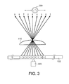
- FIG. 3 is a diagram for explaining the present invention.
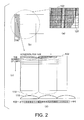
- FIG. 2(a) is a diagram showing the image display 102 and the back light 107 which is disposed on the back of the image display 102 and which can be controlled at every area with a certain desired number of divisions.
- the back light 107 is controlled on the basis of intensity of irradiating light calculated using image signals of the image display 102 corresponding to areas obtained by dividing into a desired number of portions.
- FIG. 2(b) shows an enlarged diagram of a certain irradiated area.
- an optical plate 110 having a plurality of optical apertures is disposed in front of the image display in the autostereoscopic image display apparatus.
- the optical plate 110 controls light rays emitted from pixels arranged on a matrix which is provided on the display plane of the image display 102.
- the optical plate 110 controls light rays to cause a different image to be seen according to the angle even from the same position of the optical apertures.
- a slit sheet or a lenticular sheet is used as the optical plate 110.
- a pinhole array or a fly eye lens array is used as the optical plate 110.
- the optical plate 110 may be an optical plate of switching type (active type) in which the lens effect or optical apertures can be electrically activated or deactivated.
- a graded refractive index which acts as a lens is generated by disposing a liquid crystal layer between a pair of substrates, applying a voltage between electrodes periodically arranged on one substrate included in the pair of substrates and electrodes formed on the other substrate, thereby generating electric field distribution to change the orientation of the liquid crystal layer.
- polarized light which is input to a double refraction lens formed of liquid crystal or the like is changed over by a different liquid crystal cell.
- an image (elemental image) having a plurality of parallax image components is associated with each optical aperture, i.e., each cylindrical lens.
- each optical aperture i.e., each cylindrical lens.
- nine parallax image components 1-1 to 1-9 are associated with a first cylindrical lens and nine parallax image components 2-1 to 2-9 are associated with a second cylindrical lens.
- FIG. 2(c) shows the image display 102 and the optical plate 110 viewed by a viewer.
- FIG. 2(d) shows a sectional view obtained by cutting in the horizontal direction and viewed from the bottom.
- an image (parallax image component) viewed by a viewer 200 changes depending upon a viewing position.
- an input image is an image for three-dimensional image display, for example, images corresponding to two parallaxes are necessary for the left and right eyes to view a stereoscopic image.
- the viewer 200 is located in a position at which the fourth and fifth light rays (parallax image components) arrive, the fourth and fifth parallax image components respectively are seen by the left and right eyes, as shown in FIG. 3 .
- the viewer 200 views a displayed image stereoscopically. If the image is different for every parallax even when the input image is an image for two-dimensional image display, the viewer views a different image according to the position and distance from the screen of the image display 102 to the viewer.
- an image viewed by the viewer 200 is a specific parallax image component. Therefore, it is more desirable to calculate the intensity of light illuminated from the back light according to the parallax image component viewed by the viewer 200. This can be conducted by detecting the position of the viewer 200 and the distance to the viewer by means of a camera 300 provided near the image display 102.
- a representative pixel value is selected from the two parallax image components.
- the representative determination module 104 selects a representative pixel value from the parallax image component.
- the light intensity calculation module 105 calculates the intensity of light illuminating the area on the basis of the selected pixel value.
- the back light controller 106 controls the back light 107 on the basis of the calculated light intensity.
- a plurality of parallax image components may be the same image.
- the representative pixel value means a pixel value (luminance value) of a sub-pixel.
- a representative pixel value For determining a representative pixel value from multiple parallax image components in the case of the three-dimensional image display, it is possible to calculate average values of pixel values of respective elemental images with respect to respective elemental images in a locally illuminated area and to select a maximum average value in the locally illuminated area from among those calculated average values as the representative pixel value so that the viewer can view an image from any position.
- the light intensity calculation module 105 calculates the light intensity on the basis of the selected representative pixel value.
- the back light controller 106 controls the back light 107 on the basis of the calculated light intensity. In this case, a bright image can be obtained, and an image having an insufficient luminance can also be suppressed.
- the representative pixel value is smaller as compared with the case where a pixel value of a pixel having a maximum luminance is selected as the representative, and consequently, the power dissipation can be made lower.
- the circuit scale of the light intensity calculator 103 can be made smaller.
- the light intensity calculation module 105 calculates the light intensity on the basis of the selected pixel values.
- the back light controller 106 controls the back light 107 on the basis of the calculated light intensity. In this case as well, a bright image can be obtained, and an image having an insufficient luminance can also be suppressed.
- the representative pixel value is lower as compared with the case where a pixel value of a pixel having a maximum luminance is selected as the representative, and consequently the power dissipation can be made lower.
- the circuit scale of the light intensity calculator 103 can be made smaller.
- the local dimming can be conducted effectively and picture quality degradation can be prevented when displaying a three-dimensional image, as described heretofore.
- the image display apparatus is an autostereoscopic image display apparatus.
- the present embodiment can also be applied to an image display apparatus of a scheme using glasses (for example, polarization glass scheme) in which one image includes an image for the right eye and an image for the left eye and the viewer can view this image as a three-dimensional image using glasses if each of an image for the right eye and an image for the left eye is considered to be an elemental image in the first embodiment.
- glasses for example, polarization glass scheme
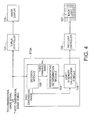
- FIG. 4 An image display apparatus according to a second embodiment is shown in FIG. 4 .
- the image display apparatus according to the second embodiment has a configuration obtained by replacing the light intensity calculator 103 in the image display apparatus shown in FIG. 1 with a light intensity calculator 103A.
- the light intensity calculator 103A has a configuration obtained by additionally providing a decision module 108 in the light intensity calculator 103.
- the decision module 108 makes a decision whether an input image signal is a three-dimensional image signal or a two-dimensional image signal. If the input image signal is a three-dimensional image signal, the decision module 108 sends the three-dimensional image signal to the representative determination module 104. If the input image signal is a two-dimensional image signal, the decision module 108 sends the two-dimensional image signal to the light intensity calculation module 105.
- the representative determination module 104 selects a representative pixel value and the light intensity calculation module 105 calculates the intensity of light illuminating a local area using the selected pixel value in the same way as described in the first embodiment.
- the back light controller 106 controls the back light 107.
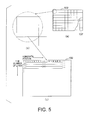
- FIG. 5(a) is a diagram showing an image display 102 and the back light 107 which is disposed on the back of the image display 102 and which can be controlled at every area with a certain desired number of divisions.
- FIG. 5(b) is an enlarged diagram showing a certain area.
- a two-dimensional image is an ordinary image which does not include a plurality of parallax images.
- the light intensity calculation module 105 calculates intensity of light illuminating an area which is illuminated locally referring to pixel values of all pixels in the area. For example, the light intensity calculation module 105 may select a maximum value from among pixel values of all pixels in the area and calculate the light intensity for illuminating the area on the basis of the maximum value. In addition, the light intensity calculation module 105 may calculate an average value of pixel values of all pixels in the locally illuminated area and calculate the light intensity for illuminating the area on the basis of the calculated average value.
- the representative determination module 104 does not operate, but the light intensity calculation module 105 calculates the light intensity for illuminating the area on the basis of the two-dimensional image signal.
- the image display apparatus is an autostereoscopic image display apparatus.
- the second embodiment can also be applied to an image display apparatus of a scheme using glasses having a shutter function if each of an image for the right eye and an image for the left eye is considered to be a two-dimensional image in the second embodiment.
- the image signal differs according to whether the image is the two-dimensional image or the three-dimensional image even if the pixel position is the same.
- the calculated light intensity differs. Therefore, it is possible to calculate an optimum light intensity to be illuminated and improve the picture quality by constructing a system which can be changed over as in the second embodiment.
- the local dimming can be conducted effectively and picture quality degradation can be prevented when displaying a three-dimensional image, in the same way as the first embodiment.
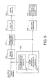
- FIG. 6 An image display apparatus according to a third embodiment is shown in FIG. 6 .
- the image display apparatus according to the third embodiment has a configuration obtained by additionally providing a frame memory 120 and an image signal correction processor 121 in the image display apparatus according to the first embodiment shown in FIG. 1 .
- a multiple parallax image signal is input to the frame memory 120 and the light intensity calculator 103.
- the intensity of light illuminating each area calculated in the light intensity calculator 103 is input to the image signal correction processor 121.
- the image signal stored in the frame memory 120 is input to the image signal correction processor 121 concurrently.
- the image signal correction processor 121 the image signal is corrected by taking the correlation between the intensity of light illuminating each area and the image signal into consideration.
- the image signal correction processor 121 conducts correction to make the pixel value of the pixel in the area greater than 50%.
- the image signal correction processor 121 conducts correction to make the pixel value of the pixel in the area less than 50%. It is possible to obtain an image having suitable brightness and suppress the picture quality degradation by conducting such correction.
- control of the back light 107 is conducted in the same way as described in the first embodiment.
- the local dimming can be conducted effectively and picture quality degradation can be prevented when displaying a three-dimensional image, in the same way as the first embodiment.
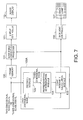
- FIG. 7 An image display apparatus according to a fourth embodiment is shown in FIG. 7 .
- the image display apparatus according to the fourth embodiment has a configuration obtained by replacing the light intensity calculator 103 in the image display apparatus according to the third embodiment shown in FIG. 6 with the light intensity calculator 103A.
- the light intensity calculator 103A has a configuration obtained by additionally providing the decision module 108 in the light intensity calculator 103.
- the configuration and the action of the light intensity device 103A are the same as those in the second embodiment.
- the local dimming can be conducted effectively and picture quality degradation can be prevented when displaying a three-dimensional image, in the same way as the first embodiment. Furthermore, the local dimming can be conducted effectively and picture quality degradation can be prevented when displaying a three-dimensional image, in the same way as the third embodiment. In addition, in the same way as the second embodiment, it is possible to calculate an optimum light intensity to be illuminated and the picture quality can be improved in each of the two-dimensional image display and the three-dimensional image display.
Landscapes
- Engineering & Computer Science (AREA)
- Multimedia (AREA)
- Signal Processing (AREA)
- Physics & Mathematics (AREA)
- Computer Hardware Design (AREA)
- General Physics & Mathematics (AREA)
- Theoretical Computer Science (AREA)
- Testing, Inspecting, Measuring Of Stereoscopic Televisions And Televisions (AREA)
- Liquid Crystal (AREA)
- Control Of Indicators Other Than Cathode Ray Tubes (AREA)
- Liquid Crystal Display Device Control (AREA)
Applications Claiming Priority (1)
| Application Number | Priority Date | Filing Date | Title |
|---|---|---|---|
| JP2011040641A JP5010746B1 (ja) | 2011-02-25 | 2011-02-25 | 画像表示装置 |
Publications (2)
| Publication Number | Publication Date |
|---|---|
| EP2492906A2 true EP2492906A2 (de) | 2012-08-29 |
| EP2492906A3 EP2492906A3 (de) | 2012-09-05 |
Family
ID=44925280
Family Applications (1)
| Application Number | Title | Priority Date | Filing Date |
|---|---|---|---|
| EP11182764A Withdrawn EP2492906A3 (de) | 2011-02-25 | 2011-09-26 | Bildanzeigevorrichtung |
Country Status (3)
| Country | Link |
|---|---|
| US (1) | US20120218255A1 (de) |
| EP (1) | EP2492906A3 (de) |
| JP (1) | JP5010746B1 (de) |
Families Citing this family (5)
| Publication number | Priority date | Publication date | Assignee | Title |
|---|---|---|---|---|
| JP5100916B2 (ja) * | 2010-09-30 | 2012-12-19 | パナソニック株式会社 | 信号処理装置およびこれを用いた映像表示装置 |
| JP5979683B2 (ja) | 2012-08-10 | 2016-08-24 | 国立研究開発法人産業技術総合研究所 | 糖鎖アイソフォーム検出方法及び糖鎖アイソフォーム検出装置 |
| KR20160117825A (ko) | 2015-03-31 | 2016-10-11 | 삼성디스플레이 주식회사 | 표시 장치 및 이의 구동 방법 |
| JP2020086381A (ja) * | 2018-11-30 | 2020-06-04 | 株式会社ジャパンディスプレイ | 画像処理装置 |
| US12293731B2 (en) * | 2021-12-17 | 2025-05-06 | Apple Inc. | Emission profile tracking for electronic displays |
Family Cites Families (12)
| Publication number | Priority date | Publication date | Assignee | Title |
|---|---|---|---|---|
| JP2000047138A (ja) * | 1998-07-27 | 2000-02-18 | Mr System Kenkyusho:Kk | 画像表示装置 |
| JP2004191490A (ja) * | 2002-12-09 | 2004-07-08 | Hitachi Displays Ltd | 液晶表示装置 |
| JP5156791B2 (ja) * | 2004-02-09 | 2013-03-06 | 株式会社ジャパンディスプレイイースト | 液晶表示装置及び画像表示装置 |
| KR100708838B1 (ko) * | 2004-06-30 | 2007-04-17 | 삼성에스디아이 주식회사 | 입체 영상 표시 장치 및 그 구동 방법 |
| JP2009049751A (ja) * | 2007-08-21 | 2009-03-05 | Toshiba Corp | 立体画像表示装置 |
| WO2009095862A1 (en) * | 2008-02-01 | 2009-08-06 | Koninklijke Philips Electronics N.V. | Autostereoscopic display device |
| WO2011001372A1 (en) * | 2009-06-30 | 2011-01-06 | Koninklijke Philips Electronics N.V. | Directional display system |
| KR101057098B1 (ko) * | 2009-07-10 | 2011-08-16 | (주)엔디스 | 광시야각 입체 디스플레이의 휘도 플리커 제어장치 및 그 방법 |
| WO2011013175A1 (ja) * | 2009-07-31 | 2011-02-03 | 株式会社 東芝 | 立体表示装置、立体表示システム |
| JP4621795B1 (ja) * | 2009-08-31 | 2011-01-26 | 株式会社東芝 | 立体視映像表示装置及び立体視映像表示方法 |
| EP2494786B1 (de) * | 2009-10-28 | 2018-07-25 | Dolby Laboratories Licensing Corporation | Stereoskopische doppelmodulator-anzeigevorrichtung mit vollfarben anaglyphen |
| US20110148930A1 (en) * | 2009-12-18 | 2011-06-23 | International Business Machines Corporation | Automatic adjustment of a display parameter based on viewer distance |
-
2011
- 2011-02-25 JP JP2011040641A patent/JP5010746B1/ja not_active Expired - Fee Related
- 2011-09-14 US US13/232,777 patent/US20120218255A1/en not_active Abandoned
- 2011-09-26 EP EP11182764A patent/EP2492906A3/de not_active Withdrawn
Non-Patent Citations (1)
| Title |
|---|
| None |
Also Published As
| Publication number | Publication date |
|---|---|
| JP2012178722A (ja) | 2012-09-13 |
| US20120218255A1 (en) | 2012-08-30 |
| EP2492906A3 (de) | 2012-09-05 |
| JP5010746B1 (ja) | 2012-08-29 |
Similar Documents
| Publication | Publication Date | Title |
|---|---|---|
| US7954967B2 (en) | Directional backlight, display apparatus, and stereoscopic display apparatus | |
| US8154799B2 (en) | 2D/3D switchable autostereoscopic display apparatus and method | |
| US9781407B2 (en) | Image display device and image display method | |
| US9088790B2 (en) | Display device and method of controlling the same | |
| JP6449428B2 (ja) | 曲面状多視点映像ディスプレイ装置及びその制御方法 | |
| US9052537B1 (en) | 2D/3D image switching type liquid crystal display | |
| KR101966152B1 (ko) | 다시점 영상 디스플레이 장치 및 그 제어 방법 | |
| US9253479B2 (en) | Method and apparatus for displaying partial 3D image in 2D image display area | |
| US10419746B2 (en) | 3D display apparatus and 3D display method | |
| CN110824725B (zh) | 3d显示基板、3d显示装置及显示方法 | |
| US9167233B2 (en) | Naked-eye stereoscopic display apparatus | |
| US9467686B2 (en) | Stereoscopic display device for stereoscopic viewing at multiple viewing points | |
| US20120327073A1 (en) | Apparatus and method for displaying 3-dimensional image | |
| US20170127050A1 (en) | Image data redundancy for high quality 3d | |
| US20140028670A1 (en) | Display device and method, and program | |
| CN103562776A (zh) | 影像显示装置以及影像显示方法 | |
| KR20170002614A (ko) | 디스플레이에 대한 구동 값들의 생성 | |
| KR20150055322A (ko) | 다시점 영상 디스플레이 장치 및 그 다시점 영상 디스플레이 방법 | |
| EP2492906A2 (de) | Bildanzeigevorrichtung | |
| US20120113358A1 (en) | Display apparatus and back light apparatus | |
| US20120033056A1 (en) | Stereoscopic Video Display Apparatus and Display Method | |
| US10025020B2 (en) | Backlight apparatus and 3D image display apparatus including the same | |
| US20130113767A1 (en) | Image display device, image display method, and integrated circuit | |
| US20140028812A1 (en) | Three-dimensional video display apparatus | |
| KR102191979B1 (ko) | 입체영상 표시장치 및 이의 구동방법 |
Legal Events
| Date | Code | Title | Description |
|---|---|---|---|
| PUAL | Search report despatched |
Free format text: ORIGINAL CODE: 0009013 |
|
| PUAI | Public reference made under article 153(3) epc to a published international application that has entered the european phase |
Free format text: ORIGINAL CODE: 0009012 |
|
| 17P | Request for examination filed |
Effective date: 20110926 |
|
| AK | Designated contracting states |
Kind code of ref document: A2 Designated state(s): AL AT BE BG CH CY CZ DE DK EE ES FI FR GB GR HR HU IE IS IT LI LT LU LV MC MK MT NL NO PL PT RO RS SE SI SK SM TR |
|
| AX | Request for extension of the european patent |
Extension state: BA ME |
|
| AK | Designated contracting states |
Kind code of ref document: A3 Designated state(s): AL AT BE BG CH CY CZ DE DK EE ES FI FR GB GR HR HU IE IS IT LI LT LU LV MC MK MT NL NO PL PT RO RS SE SI SK SM TR |
|
| AX | Request for extension of the european patent |
Extension state: BA ME |
|
| RIC1 | Information provided on ipc code assigned before grant |
Ipc: H04N 13/00 20060101ALI20120801BHEP Ipc: G09G 3/34 20060101AFI20120801BHEP |
|
| STAA | Information on the status of an ep patent application or granted ep patent |
Free format text: STATUS: THE APPLICATION HAS BEEN WITHDRAWN |
|
| 18W | Application withdrawn |
Effective date: 20130927 |