EP2492659B1 - Banc de contrôle simplifié de télescopes et télescopes auto-contrôlables - Google Patents
Banc de contrôle simplifié de télescopes et télescopes auto-contrôlables Download PDFInfo
- Publication number
- EP2492659B1 EP2492659B1 EP12155812.6A EP12155812A EP2492659B1 EP 2492659 B1 EP2492659 B1 EP 2492659B1 EP 12155812 A EP12155812 A EP 12155812A EP 2492659 B1 EP2492659 B1 EP 2492659B1
- Authority
- EP
- European Patent Office
- Prior art keywords
- optical
- objective
- telescope
- diameter
- photo
- Prior art date
- Legal status (The legal status is an assumption and is not a legal conclusion. Google has not performed a legal analysis and makes no representation as to the accuracy of the status listed.)
- Active
Links
- 238000012360 testing method Methods 0.000 title claims description 25
- 230000003287 optical effect Effects 0.000 claims description 97
- 238000001514 detection method Methods 0.000 claims description 24
- 238000004458 analytical method Methods 0.000 claims description 14
- 210000001747 pupil Anatomy 0.000 claims description 14
- 239000013307 optical fiber Substances 0.000 claims description 13
- 238000012512 characterization method Methods 0.000 claims description 11
- 238000005259 measurement Methods 0.000 description 10
- 238000000034 method Methods 0.000 description 10
- 238000012546 transfer Methods 0.000 description 4
- 239000000835 fiber Substances 0.000 description 3
- 238000000691 measurement method Methods 0.000 description 3
- 241000581464 Dactyloscopidae Species 0.000 description 1
- PEDCQBHIVMGVHV-UHFFFAOYSA-N Glycerine Chemical compound OCC(O)CO PEDCQBHIVMGVHV-UHFFFAOYSA-N 0.000 description 1
- 230000004075 alteration Effects 0.000 description 1
- 230000002238 attenuated effect Effects 0.000 description 1
- 238000013461 design Methods 0.000 description 1
- 238000006073 displacement reaction Methods 0.000 description 1
- 230000007613 environmental effect Effects 0.000 description 1
- 238000005305 interferometry Methods 0.000 description 1
- 238000004519 manufacturing process Methods 0.000 description 1
- 238000013507 mapping Methods 0.000 description 1
- 238000012544 monitoring process Methods 0.000 description 1
- 238000012545 processing Methods 0.000 description 1
- 230000000135 prohibitive effect Effects 0.000 description 1
- 238000005070 sampling Methods 0.000 description 1
- 238000013519 translation Methods 0.000 description 1
Images
Classifications
-
- G—PHYSICS
- G01—MEASURING; TESTING
- G01M—TESTING STATIC OR DYNAMIC BALANCE OF MACHINES OR STRUCTURES; TESTING OF STRUCTURES OR APPARATUS, NOT OTHERWISE PROVIDED FOR
- G01M11/00—Testing of optical apparatus; Testing structures by optical methods not otherwise provided for
- G01M11/005—Testing of reflective surfaces, e.g. mirrors
-
- G—PHYSICS
- G02—OPTICS
- G02B—OPTICAL ELEMENTS, SYSTEMS OR APPARATUS
- G02B17/00—Systems with reflecting surfaces, with or without refracting elements
- G02B17/02—Catoptric systems, e.g. image erecting and reversing system
- G02B17/06—Catoptric systems, e.g. image erecting and reversing system using mirrors only, i.e. having only one curved mirror
- G02B17/0605—Catoptric systems, e.g. image erecting and reversing system using mirrors only, i.e. having only one curved mirror using two curved mirrors
- G02B17/061—Catoptric systems, e.g. image erecting and reversing system using mirrors only, i.e. having only one curved mirror using two curved mirrors on-axis systems with at least one of the mirrors having a central aperture
-
- G—PHYSICS
- G02—OPTICS
- G02B—OPTICAL ELEMENTS, SYSTEMS OR APPARATUS
- G02B23/00—Telescopes, e.g. binoculars; Periscopes; Instruments for viewing the inside of hollow bodies; Viewfinders; Optical aiming or sighting devices
- G02B23/02—Telescopes, e.g. binoculars; Periscopes; Instruments for viewing the inside of hollow bodies; Viewfinders; Optical aiming or sighting devices involving prisms or mirrors
Definitions
- the field of the invention is that of control and measurement of the optical quality of optical instruments comprising large optical elements, of the telescope type.
- Measuring optical performance is the key point in the test campaign for a telescope after it has been assembled. It is more exactly a question of carrying out a set of measurements before and after a certain number of tests in vibratory or thermal environments in order to control the evolution of the optical performance of the instrument when it undergoes various constraints.
- the optical quality of the instrument is characterized by a phase error of the wave front, also called in English terminology "WFE", acronym meaning "Wave-Front Error”.
- WFE phase error of the wave front
- This WFE takes into account the aberrations of the telescope mirrors, but also the various misalignments of the mirrors constituting the telescope or of the detector relative to the telescope. Knowing the WFE, we deduce the Optical Transfer Function of the telescope still noted FTO. This function is linked to the previous one by a classic autocorrelation relation. Knowing the FTO optical transfer function, the FTM Modulation Transfer Function of the instrument is then calculated by switching to the module of the optical transfer function. As the misalignments between the different components of the instrument are not foreseeable, the measurement of the FTM is essential to characterize the instrument.
- the measurement of the FTM of a telescope requires the use of optical components of high optical quality, very precisely adjusted, with a diameter at least equal to that of the telescope and placed in a thermally and mechanically stabilized vacuum box to filter the vibration.
- Technical solutions of the first type consist in analyzing the optical image of a known external source, image obtained at the focal point of the telescope to determine the optical performance of the telescope.
- This type of solution has different variants.
- a collimator and a conventional FTM measurement method can be used.
- a wavefront analyzer can also be used.
- a second type of technical solution consists in implementing a wavefront analyzer on the instrument.
- One will quote, for example, the method of Shack-Hartmann consisting in carrying out a sampling of the entrance pupil to measure locally the WFE.
- a third type of solution consists in measuring the geometric characteristics of the instrument. We will cite, for example, the measurement of the distance separating the primary and secondary mirrors, videogrammetry techniques, measurement techniques by laser or "laser tracker” or even interferometry sensors.
- the patent FR 2,722,571 describes a method for characterizing an optical instrument by self-animation, the instrument comprising a detection assembly situated in the focal plane of the optical system and the test bench a large plane mirror placed in front of the entrance pupil of the instrument.
- This simple system still has a drawback. It is necessary to have a plane mirror of size equivalent to that of the pupil of the instrument.
- Reference documents CN 101 251 436 and JP 2002 228543 also discloses devices for testing an optical objective using a single plane mirror wider or the same size as the optical objective of the telescope.
- the patent FR 2 920 536 describes a control bench in which a control mirror of dimensions smaller than that of the mirror of a telescope moves in translation to ensure a complete mapping of the telescope.
- Requirement EP 0 692 707 describes a method for characterizing an optical instrument comprising a test object and a plane mirror.
- the reference document CN 101,000 232 discloses an interferometric method of controlling telescopes using a plane mirror.
- the device according to the invention does not have these drawbacks. It uses a sticker animation mirror of dimensions smaller than those of the pupil. It is clear that this mirror allows only a partial characterization of the instrument. It is however sufficient in a large number of applications where the aim of the characterization is not so much to obtain an absolute performance of the telescope but rather to measure its evolution either over time or following endurance tests or environment. In this case, the performance evolution can be detected on a partial characterization.
- the first object of the invention is an optical control bench for an optical instrument of the telescope type, the instrument (100) comprising an optical objective (110), a photo-detection unit. (120) disposed at the focus of said optical objective and at least one light source (121) disposed in the vicinity of said photo-detection unit, the optical pupil of the optical objective having a first diameter, the bench comprising a single plane mirror ( 130) having a second diameter smaller than the first diameter and means making it possible to arrange this plane mirror so that the image of the light source given by the optical objective and reflected by said plane mirror is focused on the photo- detection, said received image being a partial image of the optical objective, the bench comprising means for analyzing said received image, characterized in that the analysis means are configured to perform a partial characterization by determining the optical quality of a part of the objective on the basis of said received image, the analysis means being further configured to determine the drift optical quality of the telescope on the basis of said partial characterization.
- the analysis means include a wavefront analyzer of the images received to estimate the “WFE” of the instrument.
- the ratio of the second diameter to the first diameter is between 30% and 80% and more precisely, the ratio of the second diameter to the first diameter is approximately 60%.
- the light source comprises at least one light source and an optical fiber, one of the ends of which is arranged in the vicinity of the photosensitive surface of the photo-detection unit.
- the light source comprises at least two optical lighting fibers, the optical objective working at a predetermined wavelength, the first optical fiber being arranged in a first plane perpendicular to the optical axis of the objective and the second optical fiber arranged in a second plane parallel to the first plane and offset with respect to this first plane.
- a second object of the invention is an optical telescope (100) comprising an optical objective (110), a photo-detection unit (120) disposed at the focal point of said optical objective and at least one light source (121) disposed in the vicinity of said photo-detection unit, the optical pupil of the optical objective having a first diameter, the telescope also comprising a movable cover (140) having two positions, a first open or use position making it possible to discover the entire pupil of the objective and a second closed or test position making it possible to protect the whole pupil of the objective, the movable cover (140) comprising a single plane mirror (130) having a second diameter smaller than the first diameter and means making it possible to arrange this mirror plane so that the image of the light source given by the optical objective and reflected by said plane mirror focuses on the photo-detection unit, said image received being an imag partial e of the optical objective, the telescope comprising means for analyzing said received image, characterized in that the analysis means are configured to perform a partial characterization by determining the optical
- the ratio of the second diameter to the first diameter is between 30% and 80%.
- the ratio of the second diameter to the first diameter is around 60%.
- the light source comprises at least one light source and an optical fiber, one of the ends of which is arranged in the vicinity of the photosensitive surface of the photo-detection unit.
- the light source comprises at least two optical lighting fibers, the optical objective working at a predetermined wavelength, the first optical fiber being arranged in a first plane perpendicular to the optical axis of the lens and the second optical fiber arranged in a second plane parallel to the first plane and offset with respect to this first plane.
- the analysis means comprise by means of a wavefront analyzer of the images received to estimate the “WFE” of the instrument.
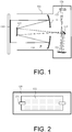
- FIG. 1 On the figure 1 , there is shown only a telescope and the self-collimation mirror necessary for its control, which is the essence of the invention.
- the mechanical means making it possible to keep the telescope and this mirror aligned are not shown. They do not represent any particular technical difficulty of implementation. Neither do the electronic analysis means necessary for processing the image from the telescope photo-detection unit appear.
- the telescope 100 includes an optical objective 110 and a photo-detection unit 120 disposed at the focal point of said optical objective.
- large telescopes have catoptic mirror objectives. So the objectives of the telescopes of figures 1 and 3 comprise a large primary mirror 111 of a first diameter, a secondary mirror 112, a folding mirror 113 and a tertiary mirror 114.
- the test bench according to the invention requires that the telescope include specific arrangements. It is necessary for the photo-detection unit 120 to include at least one light source 121 arranged in the vicinity of said photo-detection unit. The constraints entailed by this placement of sources are minor insofar as it is not necessary to touch the optical architecture or the mechanical structure of the telescope.
- a plane mirror 130 is provided in self-collimation on the optical axis of the telescope.
- This mirror 130 has a second diameter smaller than that of the large mirror 111. If one lights the light source or sources 121 arranged in the vicinity of the photo-detection block 120, their image given by the optics of the telescope and by reflection on the plane mirror 130 focuses on the photo-sensitive surface 122 of said block.
- the path of the light rays through the optics 110 of the telescope is represented by fine lines on the figures 1 and 3 .
- This image is then processed to deduce the optical quality of the telescope.
- a wavefront analyzer can be used to estimate the "WFE” of the instrument. It is possible to record several successive “WFEs”, then to post-process the estimated “WFEs”, in order to calculate via a digital model the optical performance of the instrument which can be, for example, its FTM.
- the advantage of the control method is that it is not necessary to use a self-collimating mirror having a diameter at least equal to that of the primary mirror of the instrument since, in a large number applications, and in particular during endurance or environmental tests, it is more important to check for possible deviations in the optical quality of the instrument than for its absolute performance.
- the proper functioning of the method is based on the assumption that only low frequencies of the WFE of the instrument risk being affected during the test phase, the estimates in the reduced pupil being extrapolated to the full pupil to extract optical performance information from the complete instrument or left as is if you are satisfied with local information. This assumption is entirely valid when it comes to thermal or mechanical tests since a movement of the mirrors or structures supporting them precisely involves changes in the WFE at low frequencies.
- the ratio of the second diameter of the collimating mirror to the first diameter of the telescope is between 30% and 80%.
- the ratio of the second diameter to the first diameter is around 60%.
- Fiber sources can be used in order to perfectly master the geometry of the source.
- the photo-detection block can include several sources, for example two optical fibers at each point of the field for which an optical performance measurement is desired.
- the sources can be shifted along the optical axis to be defocused relative to each other.
- the bench according to the invention makes it possible, in particular, to carry out these performance measurements in an uncontrolled environment, the telescope being placed in the air and the micro-vibrations not being attenuated by anti-vibration devices.
- the bench according to the invention makes it possible, in particular, to carry out conventional measurements of optical performance in a stabilized vacuum chamber. The estimation of the WFEs via the wavefront analyzer is then more precise.
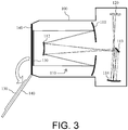
- the bench according to the invention can also be used on an observation satellite placed in orbit and comprising a space telescope 100, as seen on the figure 3 .
- the telescope is then self-controlling.
- the orientation of the cover 140 must be such that the associated mirror 130 is in the self-collimating position relative to the optic 110 of the telescope during this adjustment phase.
- the plane mirror, the sources and the analysis means then have characteristics close to those used on a test bench on the ground.
- the ratio of the second diameter to the first diameter is between 30% and 80%.
- the ratio of the second diameter to the first diameter is around 60%.
Landscapes
- Physics & Mathematics (AREA)
- General Physics & Mathematics (AREA)
- Optics & Photonics (AREA)
- Chemical & Material Sciences (AREA)
- Analytical Chemistry (AREA)
- Astronomy & Astrophysics (AREA)
- Telescopes (AREA)
Applications Claiming Priority (1)
| Application Number | Priority Date | Filing Date | Title |
|---|---|---|---|
| FR1100549A FR2972051B1 (fr) | 2011-02-24 | 2011-02-24 | Banc de controle simplifie de telescopes et telescopes auto-controlables |
Publications (2)
| Publication Number | Publication Date |
|---|---|
| EP2492659A1 EP2492659A1 (fr) | 2012-08-29 |
| EP2492659B1 true EP2492659B1 (fr) | 2019-12-25 |
Family
ID=45569531
Family Applications (1)
| Application Number | Title | Priority Date | Filing Date |
|---|---|---|---|
| EP12155812.6A Active EP2492659B1 (fr) | 2011-02-24 | 2012-02-16 | Banc de contrôle simplifié de télescopes et télescopes auto-contrôlables |
Country Status (6)
| Country | Link |
|---|---|
| US (1) | US8670113B2 (enExample) |
| EP (1) | EP2492659B1 (enExample) |
| JP (1) | JP6117473B2 (enExample) |
| CA (1) | CA2768414C (enExample) |
| FR (1) | FR2972051B1 (enExample) |
| IN (1) | IN2012DE00519A (enExample) |
Families Citing this family (2)
| Publication number | Priority date | Publication date | Assignee | Title |
|---|---|---|---|---|
| FR3011089B1 (fr) * | 2013-09-20 | 2016-12-02 | Thales Sa | Telescope comportant des moyens internes de reglage au plan focal |
| FR3074306B1 (fr) * | 2017-11-28 | 2020-06-12 | Thales | Instrument d'observation comportant un autocollimateur a miroir monte sur viseur d'etoiles |
Citations (4)
| Publication number | Priority date | Publication date | Assignee | Title |
|---|---|---|---|---|
| JP2002228543A (ja) * | 2000-11-28 | 2002-08-14 | Mitsubishi Electric Corp | 光学系ズレ推定装置、光学系ズレ調整装置、光学系ズレ推定方法、及び光学系ズレ調整方法 |
| JP2007085788A (ja) * | 2005-09-20 | 2007-04-05 | Nikon Corp | ハルトマンセンサ |
| CN101000232A (zh) * | 2007-01-17 | 2007-07-18 | 哈尔滨工业大学 | 利用干涉仪精确测量望远系统物镜和目镜间距偏差的方法 |
| CN101251436A (zh) * | 2008-03-28 | 2008-08-27 | 中国科学院上海技术物理研究所 | 卡塞格林二反射镜光学系统加工在线检验方法 |
Family Cites Families (8)
| Publication number | Priority date | Publication date | Assignee | Title |
|---|---|---|---|---|
| US5410408A (en) * | 1993-12-22 | 1995-04-25 | Hughes Aircraft Company | Optical arrangement for performing null testing of aspheric surfaces including reflective/diffractive optics |
| FR2722571B1 (fr) * | 1994-07-12 | 1996-10-04 | Aerospatiale | Procede de caracterisation d'un instrument optique par auto-collimation et instrument permettant sa mise en oeuvre |
| US6924899B2 (en) * | 2002-05-31 | 2005-08-02 | Optical Physics Company | System for measuring wavefront tilt in optical systems and method of calibrating wavefront sensors |
| CA2424023C (en) * | 2003-03-28 | 2008-10-14 | Institut National D'optique | Method and system for characterizing aspheric surfaces of optical elements |
| FR2920536B1 (fr) * | 2007-08-29 | 2010-03-12 | Thales Sa | Dispositif de mesure de la fonction de transfert de modulation d'instruments optiques de grande dimension |
| FR2938933B1 (fr) | 2008-11-25 | 2011-02-11 | Thales Sa | Systeme optique spatial comportant des moyens de controle actif de l'optique |
| JP5402011B2 (ja) * | 2009-01-20 | 2014-01-29 | 株式会社ニコン | 光学性能評価装置 |
| US8511842B1 (en) * | 2010-03-15 | 2013-08-20 | Exelis, Inc. | Eddy current based mirror wavefront control |
-
2011
- 2011-02-24 FR FR1100549A patent/FR2972051B1/fr not_active Expired - Fee Related
-
2012
- 2012-02-16 EP EP12155812.6A patent/EP2492659B1/fr active Active
- 2012-02-21 JP JP2012035408A patent/JP6117473B2/ja active Active
- 2012-02-22 CA CA2768414A patent/CA2768414C/en active Active
- 2012-02-23 US US13/403,731 patent/US8670113B2/en active Active
- 2012-02-23 IN IN519DE2012 patent/IN2012DE00519A/en unknown
Patent Citations (4)
| Publication number | Priority date | Publication date | Assignee | Title |
|---|---|---|---|---|
| JP2002228543A (ja) * | 2000-11-28 | 2002-08-14 | Mitsubishi Electric Corp | 光学系ズレ推定装置、光学系ズレ調整装置、光学系ズレ推定方法、及び光学系ズレ調整方法 |
| JP2007085788A (ja) * | 2005-09-20 | 2007-04-05 | Nikon Corp | ハルトマンセンサ |
| CN101000232A (zh) * | 2007-01-17 | 2007-07-18 | 哈尔滨工业大学 | 利用干涉仪精确测量望远系统物镜和目镜间距偏差的方法 |
| CN101251436A (zh) * | 2008-03-28 | 2008-08-27 | 中国科学院上海技术物理研究所 | 卡塞格林二反射镜光学系统加工在线检验方法 |
Also Published As
| Publication number | Publication date |
|---|---|
| JP6117473B2 (ja) | 2017-04-19 |
| FR2972051B1 (fr) | 2013-08-16 |
| US8670113B2 (en) | 2014-03-11 |
| US20130057851A1 (en) | 2013-03-07 |
| JP2012177920A (ja) | 2012-09-13 |
| IN2012DE00519A (enExample) | 2015-06-05 |
| EP2492659A1 (fr) | 2012-08-29 |
| FR2972051A1 (fr) | 2012-08-31 |
| CN102680209A (zh) | 2012-09-19 |
| CA2768414C (en) | 2019-04-02 |
| CA2768414A1 (en) | 2012-08-24 |
Similar Documents
| Publication | Publication Date | Title |
|---|---|---|
| EP3069185B1 (fr) | Dispositif et methode de mise au point tridimensionnelle pour microscope | |
| WO2010010311A2 (fr) | Dispositif optique et procede de mesure de rotation d'un objet | |
| WO2014049266A1 (fr) | Installation de mesures spectroscopiques a partir d'un plasma induit par laser | |
| EP1580524A2 (fr) | Procédé et dispositif de caractérisation d'un endommagement de structure faisant appel au moiré d'ombre | |
| EP2405287B1 (fr) | Dispositif dé telédétection laser et procédé d'interférometrie | |
| EP2050674A1 (fr) | Système de visée absolue améliorée par combinaison d'un senseur d'étoiles et d'un capteur métrologique optique de vol en formation | |
| EP2492659B1 (fr) | Banc de contrôle simplifié de télescopes et télescopes auto-contrôlables | |
| EP0840158B1 (fr) | Dispositif pour déterminer les défauts de phase d'ondes électromagnétiques | |
| EP2181315B1 (fr) | Dispositif de mesure de la fonction de transfert de modulation d'instruments optiques de grande dimension | |
| WO2013140065A1 (fr) | Système de mesure d'une zone d'écartement dans un substrat | |
| EP2520916A1 (fr) | Télescope multispectral à balayage comportant des moyens d'analyse de front d'onde | |
| EP2136239B1 (fr) | Dispositif laser comportant des moyens de mise en phase d'un grand nombre de sources coherentes | |
| FR2985811A1 (fr) | Dispositif optique, banc de test optique et procede de test optique. | |
| EP2309236B1 (fr) | Téléscope concentrateur de champ destiné à des missions de sondage atmosphérique | |
| EP2708862B1 (fr) | Instrument d'optique à analyseur de front d'onde | |
| EP3835748A1 (fr) | Systeme de controle d'au moins un composant d'un element optique | |
| EP4097423A1 (fr) | Système de mesure d'une pluralité de paramètres physiques en un point de mesure par une fibre optique multimode | |
| WO2010004110A1 (fr) | Procédé et dispositif pour la mesure de distances focales d' un système dioptrique quelconque | |
| EP0643282A1 (fr) | Dispositif optique de mesure d'écart transversal | |
| Nuzzi et al. | FLORIS PFM acceptance test results | |
| CN102680209B (zh) | 用于望远镜的简化检验平台及自检验望远镜 | |
| FR2915281A1 (fr) | Procede de determination d'une perturbation d'une onde optique | |
| Sorrente et al. | 2D index field measurement with a pyramidal sensor | |
| FR2722571A1 (fr) | Procede de caracterisation d'un instrument optique par auto-collimation et instrument permettant sa mise en oeuvre | |
| EP4078217A1 (fr) | Systeme lidar comprenant deux composants diffractifs |
Legal Events
| Date | Code | Title | Description |
|---|---|---|---|
| PUAI | Public reference made under article 153(3) epc to a published international application that has entered the european phase |
Free format text: ORIGINAL CODE: 0009012 |
|
| AK | Designated contracting states |
Kind code of ref document: A1 Designated state(s): AL AT BE BG CH CY CZ DE DK EE ES FI FR GB GR HR HU IE IS IT LI LT LU LV MC MK MT NL NO PL PT RO RS SE SI SK SM TR |
|
| AX | Request for extension of the european patent |
Extension state: BA ME |
|
| 17P | Request for examination filed |
Effective date: 20130222 |
|
| RIN1 | Information on inventor provided before grant (corrected) |
Inventor name: BENARD, HERVE Inventor name: PERRIN, GUILLAUME Inventor name: LIOTARD, ARNAUD |
|
| STAA | Information on the status of an ep patent application or granted ep patent |
Free format text: STATUS: EXAMINATION IS IN PROGRESS |
|
| 17Q | First examination report despatched |
Effective date: 20171006 |
|
| GRAP | Despatch of communication of intention to grant a patent |
Free format text: ORIGINAL CODE: EPIDOSNIGR1 |
|
| STAA | Information on the status of an ep patent application or granted ep patent |
Free format text: STATUS: GRANT OF PATENT IS INTENDED |
|
| INTG | Intention to grant announced |
Effective date: 20190726 |
|
| GRAS | Grant fee paid |
Free format text: ORIGINAL CODE: EPIDOSNIGR3 |
|
| GRAA | (expected) grant |
Free format text: ORIGINAL CODE: 0009210 |
|
| STAA | Information on the status of an ep patent application or granted ep patent |
Free format text: STATUS: THE PATENT HAS BEEN GRANTED |
|
| AK | Designated contracting states |
Kind code of ref document: B1 Designated state(s): AL AT BE BG CH CY CZ DE DK EE ES FI FR GB GR HR HU IE IS IT LI LT LU LV MC MK MT NL NO PL PT RO RS SE SI SK SM TR |
|
| RAP1 | Party data changed (applicant data changed or rights of an application transferred) |
Owner name: THALES |
|
| REG | Reference to a national code |
Ref country code: GB Ref legal event code: FG4D Free format text: NOT ENGLISH |
|
| REG | Reference to a national code |
Ref country code: CH Ref legal event code: EP |
|
| REG | Reference to a national code |
Ref country code: AT Ref legal event code: REF Ref document number: 1217647 Country of ref document: AT Kind code of ref document: T Effective date: 20200115 |
|
| REG | Reference to a national code |
Ref country code: DE Ref legal event code: R096 Ref document number: 602012066666 Country of ref document: DE |
|
| REG | Reference to a national code |
Ref country code: IE Ref legal event code: FG4D Free format text: LANGUAGE OF EP DOCUMENT: FRENCH |
|
| REG | Reference to a national code |
Ref country code: NL Ref legal event code: FP |
|
| PG25 | Lapsed in a contracting state [announced via postgrant information from national office to epo] |
Ref country code: LV Free format text: LAPSE BECAUSE OF FAILURE TO SUBMIT A TRANSLATION OF THE DESCRIPTION OR TO PAY THE FEE WITHIN THE PRESCRIBED TIME-LIMIT Effective date: 20191225 Ref country code: SE Free format text: LAPSE BECAUSE OF FAILURE TO SUBMIT A TRANSLATION OF THE DESCRIPTION OR TO PAY THE FEE WITHIN THE PRESCRIBED TIME-LIMIT Effective date: 20191225 Ref country code: LT Free format text: LAPSE BECAUSE OF FAILURE TO SUBMIT A TRANSLATION OF THE DESCRIPTION OR TO PAY THE FEE WITHIN THE PRESCRIBED TIME-LIMIT Effective date: 20191225 Ref country code: GR Free format text: LAPSE BECAUSE OF FAILURE TO SUBMIT A TRANSLATION OF THE DESCRIPTION OR TO PAY THE FEE WITHIN THE PRESCRIBED TIME-LIMIT Effective date: 20200326 Ref country code: NO Free format text: LAPSE BECAUSE OF FAILURE TO SUBMIT A TRANSLATION OF THE DESCRIPTION OR TO PAY THE FEE WITHIN THE PRESCRIBED TIME-LIMIT Effective date: 20200325 Ref country code: BG Free format text: LAPSE BECAUSE OF FAILURE TO SUBMIT A TRANSLATION OF THE DESCRIPTION OR TO PAY THE FEE WITHIN THE PRESCRIBED TIME-LIMIT Effective date: 20200325 Ref country code: FI Free format text: LAPSE BECAUSE OF FAILURE TO SUBMIT A TRANSLATION OF THE DESCRIPTION OR TO PAY THE FEE WITHIN THE PRESCRIBED TIME-LIMIT Effective date: 20191225 |
|
| REG | Reference to a national code |
Ref country code: LT Ref legal event code: MG4D |
|
| PG25 | Lapsed in a contracting state [announced via postgrant information from national office to epo] |
Ref country code: HR Free format text: LAPSE BECAUSE OF FAILURE TO SUBMIT A TRANSLATION OF THE DESCRIPTION OR TO PAY THE FEE WITHIN THE PRESCRIBED TIME-LIMIT Effective date: 20191225 Ref country code: RS Free format text: LAPSE BECAUSE OF FAILURE TO SUBMIT A TRANSLATION OF THE DESCRIPTION OR TO PAY THE FEE WITHIN THE PRESCRIBED TIME-LIMIT Effective date: 20191225 |
|
| PG25 | Lapsed in a contracting state [announced via postgrant information from national office to epo] |
Ref country code: AL Free format text: LAPSE BECAUSE OF FAILURE TO SUBMIT A TRANSLATION OF THE DESCRIPTION OR TO PAY THE FEE WITHIN THE PRESCRIBED TIME-LIMIT Effective date: 20191225 |
|
| PG25 | Lapsed in a contracting state [announced via postgrant information from national office to epo] |
Ref country code: RO Free format text: LAPSE BECAUSE OF FAILURE TO SUBMIT A TRANSLATION OF THE DESCRIPTION OR TO PAY THE FEE WITHIN THE PRESCRIBED TIME-LIMIT Effective date: 20191225 Ref country code: CZ Free format text: LAPSE BECAUSE OF FAILURE TO SUBMIT A TRANSLATION OF THE DESCRIPTION OR TO PAY THE FEE WITHIN THE PRESCRIBED TIME-LIMIT Effective date: 20191225 Ref country code: EE Free format text: LAPSE BECAUSE OF FAILURE TO SUBMIT A TRANSLATION OF THE DESCRIPTION OR TO PAY THE FEE WITHIN THE PRESCRIBED TIME-LIMIT Effective date: 20191225 Ref country code: PT Free format text: LAPSE BECAUSE OF FAILURE TO SUBMIT A TRANSLATION OF THE DESCRIPTION OR TO PAY THE FEE WITHIN THE PRESCRIBED TIME-LIMIT Effective date: 20200520 |
|
| PG25 | Lapsed in a contracting state [announced via postgrant information from national office to epo] |
Ref country code: IS Free format text: LAPSE BECAUSE OF FAILURE TO SUBMIT A TRANSLATION OF THE DESCRIPTION OR TO PAY THE FEE WITHIN THE PRESCRIBED TIME-LIMIT Effective date: 20200425 Ref country code: SK Free format text: LAPSE BECAUSE OF FAILURE TO SUBMIT A TRANSLATION OF THE DESCRIPTION OR TO PAY THE FEE WITHIN THE PRESCRIBED TIME-LIMIT Effective date: 20191225 Ref country code: SM Free format text: LAPSE BECAUSE OF FAILURE TO SUBMIT A TRANSLATION OF THE DESCRIPTION OR TO PAY THE FEE WITHIN THE PRESCRIBED TIME-LIMIT Effective date: 20191225 |
|
| REG | Reference to a national code |
Ref country code: DE Ref legal event code: R097 Ref document number: 602012066666 Country of ref document: DE |
|
| REG | Reference to a national code |
Ref country code: CH Ref legal event code: PL |
|
| REG | Reference to a national code |
Ref country code: BE Ref legal event code: MM Effective date: 20200229 |
|
| PG25 | Lapsed in a contracting state [announced via postgrant information from national office to epo] |
Ref country code: MC Free format text: LAPSE BECAUSE OF FAILURE TO SUBMIT A TRANSLATION OF THE DESCRIPTION OR TO PAY THE FEE WITHIN THE PRESCRIBED TIME-LIMIT Effective date: 20191225 Ref country code: ES Free format text: LAPSE BECAUSE OF FAILURE TO SUBMIT A TRANSLATION OF THE DESCRIPTION OR TO PAY THE FEE WITHIN THE PRESCRIBED TIME-LIMIT Effective date: 20191225 Ref country code: DK Free format text: LAPSE BECAUSE OF FAILURE TO SUBMIT A TRANSLATION OF THE DESCRIPTION OR TO PAY THE FEE WITHIN THE PRESCRIBED TIME-LIMIT Effective date: 20191225 Ref country code: LU Free format text: LAPSE BECAUSE OF NON-PAYMENT OF DUE FEES Effective date: 20200216 |
|
| PLBE | No opposition filed within time limit |
Free format text: ORIGINAL CODE: 0009261 |
|
| STAA | Information on the status of an ep patent application or granted ep patent |
Free format text: STATUS: NO OPPOSITION FILED WITHIN TIME LIMIT |
|
| REG | Reference to a national code |
Ref country code: AT Ref legal event code: MK05 Ref document number: 1217647 Country of ref document: AT Kind code of ref document: T Effective date: 20191225 |
|
| PG25 | Lapsed in a contracting state [announced via postgrant information from national office to epo] |
Ref country code: SI Free format text: LAPSE BECAUSE OF FAILURE TO SUBMIT A TRANSLATION OF THE DESCRIPTION OR TO PAY THE FEE WITHIN THE PRESCRIBED TIME-LIMIT Effective date: 20191225 Ref country code: CH Free format text: LAPSE BECAUSE OF NON-PAYMENT OF DUE FEES Effective date: 20200229 Ref country code: LI Free format text: LAPSE BECAUSE OF NON-PAYMENT OF DUE FEES Effective date: 20200229 |
|
| 26N | No opposition filed |
Effective date: 20200928 |
|
| PG25 | Lapsed in a contracting state [announced via postgrant information from national office to epo] |
Ref country code: AT Free format text: LAPSE BECAUSE OF FAILURE TO SUBMIT A TRANSLATION OF THE DESCRIPTION OR TO PAY THE FEE WITHIN THE PRESCRIBED TIME-LIMIT Effective date: 20191225 Ref country code: IE Free format text: LAPSE BECAUSE OF NON-PAYMENT OF DUE FEES Effective date: 20200216 |
|
| PG25 | Lapsed in a contracting state [announced via postgrant information from national office to epo] |
Ref country code: PL Free format text: LAPSE BECAUSE OF FAILURE TO SUBMIT A TRANSLATION OF THE DESCRIPTION OR TO PAY THE FEE WITHIN THE PRESCRIBED TIME-LIMIT Effective date: 20191225 Ref country code: BE Free format text: LAPSE BECAUSE OF NON-PAYMENT OF DUE FEES Effective date: 20200229 |
|
| PG25 | Lapsed in a contracting state [announced via postgrant information from national office to epo] |
Ref country code: TR Free format text: LAPSE BECAUSE OF FAILURE TO SUBMIT A TRANSLATION OF THE DESCRIPTION OR TO PAY THE FEE WITHIN THE PRESCRIBED TIME-LIMIT Effective date: 20191225 Ref country code: MT Free format text: LAPSE BECAUSE OF FAILURE TO SUBMIT A TRANSLATION OF THE DESCRIPTION OR TO PAY THE FEE WITHIN THE PRESCRIBED TIME-LIMIT Effective date: 20191225 Ref country code: CY Free format text: LAPSE BECAUSE OF FAILURE TO SUBMIT A TRANSLATION OF THE DESCRIPTION OR TO PAY THE FEE WITHIN THE PRESCRIBED TIME-LIMIT Effective date: 20191225 |
|
| PG25 | Lapsed in a contracting state [announced via postgrant information from national office to epo] |
Ref country code: MK Free format text: LAPSE BECAUSE OF FAILURE TO SUBMIT A TRANSLATION OF THE DESCRIPTION OR TO PAY THE FEE WITHIN THE PRESCRIBED TIME-LIMIT Effective date: 20191225 |
|
| PGFP | Annual fee paid to national office [announced via postgrant information from national office to epo] |
Ref country code: NL Payment date: 20250127 Year of fee payment: 14 |
|
| PGFP | Annual fee paid to national office [announced via postgrant information from national office to epo] |
Ref country code: DE Payment date: 20250114 Year of fee payment: 14 |
|
| PGFP | Annual fee paid to national office [announced via postgrant information from national office to epo] |
Ref country code: FR Payment date: 20250121 Year of fee payment: 14 |
|
| PGFP | Annual fee paid to national office [announced via postgrant information from national office to epo] |
Ref country code: IT Payment date: 20250129 Year of fee payment: 14 Ref country code: GB Payment date: 20250116 Year of fee payment: 14 |