EP2492491A1 - Pumpen- Anordnung - Google Patents
Pumpen- Anordnung Download PDFInfo
- Publication number
- EP2492491A1 EP2492491A1 EP11156279A EP11156279A EP2492491A1 EP 2492491 A1 EP2492491 A1 EP 2492491A1 EP 11156279 A EP11156279 A EP 11156279A EP 11156279 A EP11156279 A EP 11156279A EP 2492491 A1 EP2492491 A1 EP 2492491A1
- Authority
- EP
- European Patent Office
- Prior art keywords
- drive
- pumping
- plate
- guide
- base plate
- Prior art date
- Legal status (The legal status is an assumption and is not a legal conclusion. Google has not performed a legal analysis and makes no representation as to the accuracy of the status listed.)
- Withdrawn
Links
- 238000005086 pumping Methods 0.000 title claims abstract description 164
- 239000000446 fuel Substances 0.000 claims abstract description 55
- 238000002347 injection Methods 0.000 claims abstract description 16
- 239000007924 injection Substances 0.000 claims abstract description 16
- 230000001419 dependent effect Effects 0.000 claims 1
- 239000012530 fluid Substances 0.000 description 7
- 230000000712 assembly Effects 0.000 description 6
- 238000000429 assembly Methods 0.000 description 6
- 230000007423 decrease Effects 0.000 description 5
- 238000002485 combustion reaction Methods 0.000 description 4
- 238000010586 diagram Methods 0.000 description 2
- 239000002828 fuel tank Substances 0.000 description 2
- 238000012986 modification Methods 0.000 description 2
- 230000004048 modification Effects 0.000 description 2
- 238000006243 chemical reaction Methods 0.000 description 1
- 230000000694 effects Effects 0.000 description 1
- 206010016256 fatigue Diseases 0.000 description 1
- 239000000314 lubricant Substances 0.000 description 1
- 238000004519 manufacturing process Methods 0.000 description 1
- 230000001105 regulatory effect Effects 0.000 description 1
- 239000000243 solution Substances 0.000 description 1
- 239000007921 spray Substances 0.000 description 1
- 230000001360 synchronised effect Effects 0.000 description 1
Images


Classifications
-
- F—MECHANICAL ENGINEERING; LIGHTING; HEATING; WEAPONS; BLASTING
- F02—COMBUSTION ENGINES; HOT-GAS OR COMBUSTION-PRODUCT ENGINE PLANTS
- F02M—SUPPLYING COMBUSTION ENGINES IN GENERAL WITH COMBUSTIBLE MIXTURES OR CONSTITUENTS THEREOF
- F02M59/00—Pumps specially adapted for fuel-injection and not provided for in groups F02M39/00 -F02M57/00, e.g. rotary cylinder-block type of pumps
- F02M59/02—Pumps specially adapted for fuel-injection and not provided for in groups F02M39/00 -F02M57/00, e.g. rotary cylinder-block type of pumps of reciprocating-piston or reciprocating-cylinder type
- F02M59/10—Pumps specially adapted for fuel-injection and not provided for in groups F02M39/00 -F02M57/00, e.g. rotary cylinder-block type of pumps of reciprocating-piston or reciprocating-cylinder type characterised by the piston-drive
- F02M59/102—Mechanical drive, e.g. tappets or cams
-
- F—MECHANICAL ENGINEERING; LIGHTING; HEATING; WEAPONS; BLASTING
- F04—POSITIVE - DISPLACEMENT MACHINES FOR LIQUIDS; PUMPS FOR LIQUIDS OR ELASTIC FLUIDS
- F04B—POSITIVE-DISPLACEMENT MACHINES FOR LIQUIDS; PUMPS
- F04B1/00—Multi-cylinder machines or pumps characterised by number or arrangement of cylinders
- F04B1/04—Multi-cylinder machines or pumps characterised by number or arrangement of cylinders having cylinders in star- or fan-arrangement
- F04B1/0404—Details or component parts
-
- F—MECHANICAL ENGINEERING; LIGHTING; HEATING; WEAPONS; BLASTING
- F04—POSITIVE - DISPLACEMENT MACHINES FOR LIQUIDS; PUMPS FOR LIQUIDS OR ELASTIC FLUIDS
- F04B—POSITIVE-DISPLACEMENT MACHINES FOR LIQUIDS; PUMPS
- F04B9/00—Piston machines or pumps characterised by the driving or driven means to or from their working members
- F04B9/02—Piston machines or pumps characterised by the driving or driven means to or from their working members the means being mechanical
- F04B9/04—Piston machines or pumps characterised by the driving or driven means to or from their working members the means being mechanical the means being cams, eccentrics or pin-and-slot mechanisms
Definitions
- This invention relates to a pumping assembly for pumping a fluid.
- the invention relates to a pumping assembly suitable for use in a high-pressure fuel pump of a fuel injection system for an internal combustion engine.
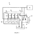
- FIG. 1 of the accompanying drawings is a schematic diagram of a conventional fuel injection system 10 for an internal combustion engine.
- the fuel injection system 10 comprises a plurality of fuel injectors 12. Each injector 12 is arranged to deliver an atomised spray of high-pressure fuel to a respective combustion chamber (not shown) of the engine.
- the injectors 12 receive fuel at high pressure from an accumulator volume or rail 14, by way of high-pressure supply lines 16.
- the rail 14 comprises a reservoir for high-pressure fuel.
- Delivery of fuel from the injectors 12 is controlled by an electronic control unit 18.
- the electronic control unit 18 sends an actuation signal to the injector 12, which causes actuation of a delivery valve (not shown) of the injector 12.
- Fuel is pumped to the rail 14 from a storage tank 20 by a fuel pump assembly 22.
- the fuel pump assembly 22 includes a low-pressure transfer pump 24, which serves to convey fuel from the tank 20 to the pump assembly 22, and a high-pressure pump 26 which elevates the pressure of the fuel to the injection pressure, typically of the order of 2000 bar.
- Fuel is conveyed from the tank 20 to the pump assembly 22 by way of a low-pressure fuel line 28, and from the pump assembly 22 to the rail by way of a high-pressure fuel line 30.
- An inlet metering valve 32 under the control of the engine control unit 18, is provided between the transfer pump 24 and the high-pressure pump 26 of the pump assembly 22.
- the inlet metering valve 32 determines how much fuel reaches the high-pressure pump 26, for subsequent pressurisation and delivery to the rail 14.
- the fuel pressure in the rail 14 is regulated to a target value by the electronic control unit 18.
- a pressure-limiting valve 36 and return line 38 prevent the rail pressure exceeding a pre-determined acceptable level.
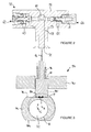
- the high-pressure pump 26 comprises a pumping head 50, shown schematically in Figure 2 , which is arranged to receive a reciprocable pumping plunger or pumping element 52.
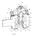
- the pump 26 further comprises a drive assembly 54, shown schematically in Figure 3 , for driving reciprocal movement of the pumping element 52. It should be noted that the cross-sectional views of the pumping head 50 and the drive assembly 54 in Figures 2 and 3 respectively are not to scale.
- the pumping head 50 comprises a housing 56 that includes a blind bore 58.
- the pumping element 52 is slidably received within the bore 58.
- a pumping chamber 60 at the blind end of the bore 58 is defined in part by the pumping member 52 and in part by the bore 58.
- the pumping head 50 further comprises a spring-biased inlet valve 62 and a spring-biased outlet valve 64.
- a spring-biased inlet valve 62 When the pumping element 52 moves downwards (referred to as a filling stroke or return stroke of the pumping element 52), the volume of the pumping chamber 60 increases, the outlet valve 64 closes, and the inlet valve 62 opens when the pressure differential across it reaches a first predetermined level. Fuel is then admitted to the pumping chamber 60 from a fuel supply passage 63, through the inlet valve 62. The fuel supply passage 63 is fed with fuel from the inlet metering valve (32 in Figure 1 ).
- the pumping element 52 moves upwards (referred to as a pumping stroke or forward stroke of the pumping element 52), the volume of the pumping chamber 60 decreases.
- the inlet valve closes 62, and the pressure of fuel in the pumping chamber 60 increases.
- the outlet valve 64 is arranged to open when the pressure differential across it reaches a second pre-determined level. Fuel is then delivered through the outlet valve 64 from the pumping chamber 60, for delivery to the fuel rail 14 through an outlet passage 65.
- the second pre-determined differential pressure level at a high level, for example 2000 bar or more, the fuel rail 14 can be pressurised to a suitably high pressure for injection.
- the drive assembly 54 comprises a housing 70, also known as a cam box, which houses a cylindrical cam 72.
- the housing 70 is only partially shown in Figure 3 .
- the cam 72 is driven in eccentric rotational movement by a drive shaft (not shown in Figure 3 ) that extends through the housing 70, so that the cylinder axis C of the cam describes a circular path around the axis A of the drive shaft (which extends normal to the drawing plane in Figure 3 ) as the drive shaft rotates.
- the path described by the edge of the cam 72 as it rotates is indicated by the dashed line P in Figure 3 .
- the drive shaft has a smaller diameter than the cam 72.
- the cam 72 carries a cam ring or rider 74, which includes a central cylindrical aperture 76 for receiving the cam 72.
- the rider 74 includes a flattened surface region or flat 78, which is arranged to cooperate with a cam follower or tappet 80 that acts as a drive member for the pumping element 52.
- the cam 72 is free to rotate in the aperture 76, so that the orientation of the flat 78 of the rider 74 remains horizontal in use.
- the tappet 80 is guided for reciprocal movement through an opening 82 in the housing 70, and is coupled to the pumping element 52 so that movement of the tappet 80 causes movement of the pumping element 52.
- the tappet 80 includes a flat base surface 84 that is held in sliding contact with the flat 78 of the cam rider 74 by a biasing spring 86.
- the housing 70 contains a lubricant (conveniently fuel) that lubricates the sliding interfaces between the tappet 80 and the rider 74 and between the tappet and the wall of the opening 82.
- the drive shaft rotates about its axis A, in a clockwise direction in Figure 3 , causing eccentric clockwise movement of the cam 72.
- the cam 72 carries the rider 74 in a path having an upward component, towards the opening 82 in the housing 70.
- the tappet 80 is driven upwards by the rider 74, so as to drive the forward stroke of the pumping element (52 in Figure 2 ).
- the biasing spring 86 keeps the tappet 80 in engagement with the flat 78 of the rider 74, so that the tappet 80 moves downwards and the pumping element (52 in Figure 2 ) is therefore driven by the biasing spring 86 in its return stroke.
- the pumping cycle repeats as the drive shaft continues to rotate.
- the high-pressure pump 26 In high-pressure fuel injection systems, the high-pressure pump 26 must be able to deliver a sufficient quantity of fuel to the rail 14 to meet the demand from the fuel injectors 12. At particularly high engine loads, the fuel demand can be considerable.
- One solution to maintaining sufficient fuel output from the high-pressure pump 26 is to increase the drive speed of the drive shaft, to increase the rate of pumping.
- the pumping rate can, however, be limited by the ability of the biasing spring 86 to keep the tappet 80 in contact with the rider 74 on the return stroke of the pumping element 52. Also, as the pumping rate increases, the risk of fatigue damage to the spring 86 increases.
- a pumping assembly suitable for use as high-pressure fuel pump in a fuel injection system.
- the pumping assembly includes drive means comprising a drive plate rotatable about a drive axis and including a recess arranged eccentrically with respect to the drive axis, a guide arrangement received, at least in part, in the recess of the drive plate so that rotary movement of the drive plate gives rise to translatory movement of the guide arrangement, a pumping element, and a slide member associated with the pumping element.
- the slide member is in sliding engagement with the guide arrangement to define at least one sliding interface between the guide arrangement and the slide member, such that rotary movement of the drive plate causes reciprocal linear movement of the pumping element along a pumping axis.
- the present invention provides a space-efficient pumping assembly in which the forces that arise in use are distributed more evenly throughout the components compared to known arrangements.
- the pumping element preferably defines, in part, a pumping chamber of a pumping head.
- the pumping element causes a decrease in the volume of the pumping chamber during a forward stroke of the pumping element, and an increase in volume of the pumping chamber during a return stroke of the pumping element.
- the guide arrangement cooperates with the slide member at parallel first and second sliding interfaces between the guide arrangement and the slide member. Both the forward and return strokes of the pumping element can therefore be driven by the pumping assembly with substantially equal force. Accordingly, no biasing spring or other return mechanism for the pumping element need be provided, and the torque required to drive the pumping action is relatively constant.
- the first and second sliding interfaces may be arranged on opposite sides of the slide member. The slide member may be embraced by the guide arrangement.
- the slide member comprises a plate assembly provided at an end of the pumping element, and the guide arrangement cooperates with first and second oppositely-facing surfaces of the plate assembly at the first and second sliding interfaces, respectively.
- the first and second surfaces may lie in planes that are normal to the pumping axis.
- the plate assembly may comprise a first slide plate engaged with the pumping element and a second slide plate.
- the second slide plate may receive an end of the pumping element, so that the first and second slide plates cooperate to retain the pumping element.
- the guide arrangement may comprise at least one first guide member that cooperates with the slide member at the first sliding interface, and at least one second guide member that cooperates with the slide member at the second sliding interface.
- the or each first guide member may be spaced apart from the or each second guide member in a direction parallel to the pumping axis.
- the or each first guide member and the or each second guide members may extend in a direction parallel to the drive axis.
- the pumping element may extend through a gap between two of the first guide members.
- the first and second guide members preferably embrace the slide member therebetween, so that rotary movement of the drive plate is converted to linear movement of the pumping element during both the forward and reverse strokes of the pumping cycle.
- the or each first guide member may be an upper guide member, and the or each second guide member may be a lower guide member, with reference to the slide member in one orientation of the pumping assembly.
- the guide arrangement may comprise at least one base plate from which the guide members extend.
- the guide arrangement comprises a first base plate and an opposing second base plate spaced from the first base plate in a direction parallel to the drive axis, in which case the first and second guide members may extend between the first and second base plates.
- the base plates are preferably circular in cross-section, for example disc-shaped.
- At least one of the guide members may extend from the first base plate to engage with a slot in the second base plate. Similarly at least one of the guide members may extend from the second base plate to engage with a slot in the first base plate.
- the first and second base plates and the respective guide members define opposing, interlocking guide bodies of the guide arrangement that together cooperate with the slide member at parallel first and second sliding interfaces.
- At least one first guide member and at least one second guide member extend from each base plate to engage with respective first and second slots in the opposing base plate.
- one first guide member and one second guide member may extend from each base plate, and the first guide member may be disposed on the opposite side of the pumping axis to the second guide member that extends from the same base plate.
- the drive means comprises first and second drive plates spaced apart along the drive axis.
- Each drive plate is rotatable about the drive axis and includes a recess arranged eccentrically with respect to the drive axis.
- the first and second drive plates oppose one another to accommodate the guide arrangement therebetween, and the guide arrangement is received in part in the recess in the first drive plate and in part in the recess in the second drive plate.
- both ends of the drive assembly can be supported by and driven by the drive means, which advantageously reduces stresses in the guide arrangement.
- the first base plate may be received, at least in part, in the recess in the first drive plate
- the second base plate may be received, at least in part, in the recess in the second drive plate
- the pumping assembly may further comprise a drive shaft for transmitting drive from the first drive plate to the second drive plate. In this way, rotary movement of the second drive plate is synchronised with rotary movement of the first drive plate.
- the first drive plate may be driven by a primary drive shaft that defines the drive axis.
- the pumping axis may be perpendicular to the drive axis.
- the pumping assembly may further comprise a pumping head comprising a bore for receiving the pumping element, and a pumping chamber defined in part by the bore and in part by the pumping element, wherein reciprocal linear movement of the pumping element causes a cyclical change in volume in the pumping chamber.
- the invention resides in a fuel pump for a fuel injection system, comprising a pumping assembly according to the first aspect of the invention.
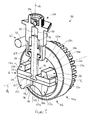
- a pumping assembly 100 comprises a drive mechanism 102 and a pumping head 104.
- the drive mechanism 102 cooperates with a rotary drive shaft 106 (not visible in Figure 5 ) that defines a drive axis A.
- a pumping element or plunger 108 is driven in linear reciprocal motion by the drive mechanism 102, along a pumping axis Q that is perpendicular to the drive axis A.
- the drive mechanism 102 comprises first and second drive assemblies 110, 110a disposed either side of the plunger 108 and spaced apart along the drive axis A.
- the drive assemblies 110, 110a cooperate with a slide member 112 associated with the plunger 108 to cause conversion of the rotary movement of the drive assemblies 110, 110a to linear reciprocating movement of the plunger 108.
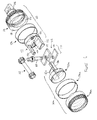
- the first drive assembly 110 (shown most clearly in Figure 4 and in exploded view in Figures 6 and 7 ) comprises a drive plate 114 of generally cylindrical or disc-shaped form, having oppositely-facing generally circular faces 116, 118.
- the cylinder axis of the drive plate 114 is coaxial with the drive axis A, and the drive shaft 106 extends from the outermost face 116 of the drive plate 114.
- the drive shaft 106 is integral with the drive plate 114, although in other embodiments the drive shaft 106 may be a separate component that is attached to or otherwise cooperates with the drive plate 114.
- An eccentrically-arranged circular recess 120 is formed in the innermost face 118 of the drive plate 114, as shown most clearly in Figures 6 and 7 .
- the recess 120 receives a guide body 122 of the first drive assembly 110, shown additionally in Figure 8 .
- the guide body 122 comprises a generally cylindrical base plate 124 that is received rotatably in the recess 120 of the drive plate 114.
- a first, outermost face 126 of the base plate 124 abuts the back wall of the recess 120.
- a second, innermost face 128 of the base plate 124, opposite the outermost face 126, is approximately coplanar with the innermost face 118 of the drive plate 114, in use.
- a first guide member 130 (hereafter referred to as an upper guide member) and a second guide member 132 (hereafter referred to as a lower guide member) project from the innermost face 128 of the guide body base plate 124, towards the second drive assembly 110a, in a direction parallel to the drive axis A (see Figures 4 and 6 ).
- a lower face 134 of the upper guide member 130 is formed as a flat guide surface.
- the upper face 136 of the lower guide member 132 is formed as a flat guide surface.
- the outermost side faces 138, 140 of each guide member 130, 132 are curved to lie within a cylindrical envelope defined by the base plate 124.
- An upper recess or slot 142 and a lower recess or slot 144 are formed in the innermost face 128 of the base plate 124.
- the upper and lower slots 142, 144 of the base plate 124 are shaped to receive corresponding guide members of a guide body 122a that forms part of the second drive assembly 110a.
- the generally cylindrical edge surface of the drive plate 114 comprises a toothed region 150 closest to the outermost face 116, and a smooth cylindrical bearing surface 152 closest to the innermost face 118.
- the bearing surface 152 rides in a plain bearing 154.
- the bearing 154 is mounted in a housing (not shown) of the pumping arrangement, so that the drive plate 114 can rotate about the drive axis A in use.
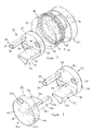
- the second drive assembly 110a which is visible in Figures 4 and 5 , is substantially the same as the first drive assembly 110, and the suffix 'a' is used in the reference numerals to denote a feature of the second drive assembly 110a that has a counterpart feature with a corresponding reference numeral in the first drive assembly 110.
- the second drive assembly 110a When assembled in the pumping arrangement, the second drive assembly 110a is oriented at 180 degrees to the first drive assembly 110, with respect to the pumping axis Q.
- the drive plate 114a of the second drive assembly 110a includes oppositely-facing generally circular faces 116a, 118a.
- the cylinder axis of the drive plate 114a is coaxial with the drive axis A.
- the drive plate 114a of the second drive assembly 110a does not connect directly to the drive shaft 106.
- An eccentrically-arranged circular recess 120a in the innermost face 118a of the drive plate 114a receives a guide body 122a of the second drive assembly 110a, shown additionally in Figure 8 .
- the guide body 122a is identical to the guide body 122 of the first drive assembly 110, and therefore comprises a base plate 124a having first and second faces 126a, 128a, and upper and lower guide members 130a, 132a with respective guide surfaces 134a, 136a.
- the upper and lower guide members 130a, 132a project from the innermost face 128a of the guide body base plate 124a, towards the first drive assembly 110a, in a direction parallel to the drive axis A.
- the outermost side faces 138a, 140a of each guide member 130a, 132a are curved to lie within a cylindrical envelope defined by the base plate 124a.
- the upper and lower guide members 130a, 132a are therefore shaped so that the end of each guide member 130a, 132a can be received in the corresponding upper and lower slots 142, 144 of the base plate 124 of the first drive assembly 110.
- An upper recess or slot 142a and a lower recess or slot 144a are formed in the innermost face 128a of the guide body base plate 124a.
- the upper and lower slots 142a, 144a of the base plate 124a are shaped to receive the corresponding guide members 130, 132 of the guide body 122 of the first drive assembly 110.
- the generally cylindrical edge surface of the drive plate 114a of the second drive assembly 110a comprises a toothed region 150a closest to the outermost face 116a, and a smooth cylindrical bearing surface 152a closest to the innermost face 118a.
- the bearing surface 152a rides in a plain bearing 154a.
- the bearing 154a is mounted in the housing of the pump assembly, so that the drive plate 114a can rotate about the drive axis A in use.
- the eccentric recesses 120, 120a of the first and second drive assemblies 110, 110a are arranged in the same angular position around the drive axis A, so that the guide bodies 122, 122a received in the recesses 120, 120a cooperate with one another to form an interlocking guide arrangement for the slide member 112 associated with the plunger 108.
- FIG 8 is an exploded view of the pumping arrangement showing only the guide bodies 122, 122a (the other components of the arrangement are omitted from Figure 8 , for clarity), an end region of the upper guide member 130 of the first drive assembly 110 is received within the upper slot 142a of the guide body 122a of the second drive assembly 110a, when assembled. An end region of the upper guide member 130a of the guide body 122a of the second drive assembly 110a is received within the upper slot 142 of the guide body 122 of the first drive assembly 110.
- the guide surfaces 134, 134a formed by the lower faces of each of the upper guide members 130, 130a are substantially coplanar, as shown most clearly in Figure 5 .
- the upper guide members 130, 130a are spaced apart to define a gap 156 therebetween.
- an end region of the lower guide member 132 of the first drive assembly 110 is received within the lower slot 144a of the guide body 122a of the second drive assembly 110a, and an end region of the lower guide member 132a of the guide body 122a of the second drive assembly 110a is received within the lower slot 144 of the guide body 122 of the first drive assembly 110.
- the guide surfaces 136, 136a formed by the upper faces of each of the lower guide members 132, 132a are also substantially coplanar, as shown most clearly in Figure 5 .
- the lower guide members 132, 132a meet so that there is substantially no gap between the guide surfaces 136, 136a in the assembled pumping arrangement.
- the pumping arrangement also includes a drive axle 162 to transmit drive between the first and second drive assemblies 110, 110a.
- the drive axle 162 comprises a shaft 164 and first and second gears 166, 166a disposed at opposite ends of the shaft.
- the drive axle 162 is mounted in suitable bearings (not shown) in the housing of the pumping arrangement.
- the first gear 166 is engaged with the toothed region 150 of the drive plate 114 of the first drive assembly 110
- the second gear 166a is engaged with the toothed region 150a of the drive plate 114a of the second drive assembly 110a.
- the drive plates 114, 114a and the drive axle 162 together provide a drive means for the pumping arrangement.
- the drive axle 162 transmits rotational movement of the drive plate 114 of the first drive assembly 110 to the drive plate 114a of the second drive assembly 110a. Accordingly, when the drive shaft 106 rotates, the drive plates 114, 114a of each of the first and second drive assemblies 110, 110a rotate at the same rotational speed, and the recesses 120, 120a in the drive plates 114, 114a remain in alignment along the drive axis A.
- the interlocking guide arrangement formed by the two guide bodies 122, 122a is thereby carried in an eccentric movement about the drive axis A, with the cylinder axis defined by the interlocking guide bodies 122, 122a remaining parallel to the drive axis A.
- the interlocking guide bodies 122, 122a together cooperate with a plunger assembly 170, shown most clearly in exploded view in Figure 9 , and also visible in assembled form in Figures 4 and 5 .
- the plunger assembly 170 comprises the pumping plunger 108 and the slide member 112.
- the slide member 112 includes an upper slide plate 172, and a lower slide plate 174.
- the plunger 108 comprises an upper end portion 176 that is received in a pumping head (200 in Figures 4 and 5 ), and a lower end portion 178 remote from the upper end 176.
- the slide plates 172, 174 are generally rectangular, and are arranged so that the plane of each slide plate 172, 174 is perpendicular to the pumping axis Q, and hence to the plunger 108.
- An annular recess 180 extends around the lower end portion 178 of the plunger 108.
- the upper slide plate 172 is provided with a slot 182 that extends inwardly from one of the long edge faces of the plate 172, in a direction parallel to the drive axis A.
- the plunger 108 is received in the slot 182, as shown in Figures 4 and 5 , so that the upper slide plate 172 is mounted to or attached to the plunger 108.
- the slot 182 is profiled through the thickness direction of the slide plate 172 so that it corresponds to the shape of the part of the lower end portion 178 of the plunger 108, including the recess 180, which mates with the slot 182.
- the position and length of the slot 182 is such that the plunger 108 is positioned approximately centrally with respect to the upper slide plate 172.
- the lower slide plate 174 has substantially the same in-plane dimensions as the upper slide plate 172.
- the upper face 184 of the lower slide plate 174 is provided with a circular recess 186 for receiving the lowermost end of the plunger 108.
- the lower face of the upper slide plate 172 abuts the upper face 184 of the lower slide plate 174 when assembled, and the slot 182 in the upper slide plate 172 and the recess 186 in the lower slide plate 174 serve together to retain the plunger 108.
- the plunger slide member 112 is positioned between the upper guide members 130, 130a and the lower guide members 132, 132a of the interlocking guide bodies 122, 122a, so that the upper and lower slide plates 172, 174 are embraced in a sliding relationship between the guide surfaces 134, 134a, 136, 136a.
- the guide surfaces 134, 134a defined by the lower faces of the upper guide members 130, 130a are in sliding contact with the upper face of the upper slide plate 172
- the guide surface 136, 136a defined by the upper faces of the lower guide members 132, 132a are in sliding contact with the lower face of the lower slide plate 174.
- the plunger 108 extends upwardly from the slide member 112 through the gap 156 between the upper guide memers 130, 130a.
- the upper end region 176 of the plunger 108 is slidably received within the pumping head 104, which is mounted to the housing (not shown) of the pumping arrangement.
- the pumping head 104 may be of any suitable type, and may for example operate in accordance with the principles of the known pumping head described with reference to Figure 2 .
- the pumping head 104 comprises a generally cylindrical housing 188 having a blind bore 190 that extends upwardly from a lower end of the housing.
- a pumping chamber 192 is defined in part by the bore 190 and in part by the top end of the plunger 108.
- the pumping chamber 192 is in communication with an inlet valve (not shown) and an outlet valve 194.
- the inlet valve When in use as a fuel pump in a fuel injection system, the inlet valve communicates with a fuel source (not shown) such as a fuel tank, optionally by way of an inlet metering valve (not shown) and/or a transfer pump (not shown), and the outlet valve 194 communicates with a high-pressure fluid line (not shown) that delivers fuel to a fuel rail (not shown) of the injection system.
- a fuel source such as a fuel tank
- an inlet metering valve not shown
- a transfer pump not shown
- the outlet valve 194 communicates with a high-pressure fluid line (not shown) that delivers fuel to a fuel rail (not shown) of the injection system.
- the plunger 108 is driven in reciprocal linear movement within the bore 190, as will be described in more detail below.
- the outlet valve 194 is configured to open when the pressure of fluid in the pumping chamber 192 reaches a threshold value, so as to deliver the pressurised fluid through the outlet valve 194.
- the volume of the pumping chamber 192 increases to cause a decrease in fluid pressure in the pumping chamber 192. This causes the outlet valve to close and the inlet valve to open, so that fluid is admitted to the pumping chamber 192 through the inlet valve.
- the forward and return strokes of the plunger 108 therefore define a pumping cycle in which fuel is pumped from the pumping head 104 to a fuel rail at relatively high pressure, and drawn into the pumping head 104 from a fuel tank at relatively low pressure.
- Operation of the drive mechanism 102 will now be described with reference to Figures 10(a) to 10(d) , which are schematic, simplified cross-sectional views of the drive mechanism 102 at successive stages of a pumping cycle.
- the following description refers to the second drive assembly 110a, which is visible in Figures 10(a) to 10(d) , but it will be understood that the first drive assembly 110 (not visible in Figures 10(a) to 10(d) ) also undergoes corresponding movement in operation.
- Figure 10(a) shows the drive mechanism 102 when the plunger 108 is at its lowest extent of travel, known as the bottom dead centre (BDC) position.
- BDC bottom dead centre
- the translational movement of the guide members 130, 130a, 132, 132a of the guide bodies 122, 122a results in upward movement of the slide plates 172, 174, and therefore the plunger 108, driving the forward stroke of the plunger 108.
- the guide members 130, 130a, 132, 132a slide to the left with respect to the slide plates 172, 174, in a direction perpendicular to both the pumping axis Q and the drive axis A.
- a first sliding interface 196 is defined between the upper guide members 130, 130a and the upper face of the upper slide plate 172
- a second sliding interface 198 is defined between the lower guide members 132, 132a and the lower face of the lower slide plate 172.
- the first and second sliding interfaces 196, 198 remain parallel to one another in use, and each sliding interface 196, 198 lies in a plane that is normal to the pumping axis Q. Accordingly, the sliding interfaces 196, 198 prevent rotation of the guide bodies 122, 122a around their own cylinder axes. Instead, the guide bodies 122, 122a rotate within the recesses 120, 120a so that the orientation of each sliding interface 196, 198 remains constant.
- both the forward and return strokes of the plunger 108 are driven by the drive mechanism 102. It is not therefore necessary to provide a return spring in the arrangement of the invention.
- the configuration of the guide arrangement may differ from that described above. Any suitable configuration that cooperates with the slide member in a sliding engagement could be used. It is conceivable that only one sliding interface between the slide member and the guide arrangement could be present, in which case, if necessary, a biasing or return spring could be employed to keep the plunger assembly in sliding engagement with the guide arrangement during the return stroke.
- the plunger assembly may vary from that described above.
- a slide member comprising upper and lower slide plates that cooperate with the plunger
- a single slide plate could be provided.
- the plunger could be attached or attachable to the guide arrangement in alternative ways, such as by a screw-threaded engagement or any other mechanical engagement.
- the plunger could be formed integrally with one or more parts of the guide arrangement.
- Bearings may be provided between the guide bodies and the recesses of the drive plates, in order to prevent wear due to the relative rotation of these components in use. Similarly, bearings could be provided at the sliding interfaces between the plunger guide arrangement and the guide members.
- the total thickness of the plunger slide member arrangement i.e. the combined thickness of the upper and lower slide plates in the embodiment described above
- the guide members and/or the slide plates may be machined during manufacture to achieve close tolerances between these parts.
- an adjustment mechanism may be provided to adjust the thickness of the plunger slide member or the distance between the upper and lower guide members.
- the drive axle is advantageous in minimising the torque experienced by the components between the drive plates.
- the drive axle could be omitted, in which case rotation of the drive plate that is not driven by the drive shaft would still be coupled to rotation of the driven drive plate by virtue of the interlocking guide bodies received in the recesses in each drive plate.
- the guide body could comprise a suitable arrangement of guide members to engage with the plunger guide arrangement on each side of the plunger.
- suitable retaining means could be provided to retain the plunger assembly in engagement with the guide body, and to retain the guide body in engagement with the drive plate.
- the retaining means could comprise a wall of the pump assembly housing.
Landscapes
- Engineering & Computer Science (AREA)
- Mechanical Engineering (AREA)
- General Engineering & Computer Science (AREA)
- Chemical & Material Sciences (AREA)
- Combustion & Propulsion (AREA)
- Fuel-Injection Apparatus (AREA)
Priority Applications (1)
| Application Number | Priority Date | Filing Date | Title |
|---|---|---|---|
| EP11156279A EP2492491A1 (de) | 2011-02-28 | 2011-02-28 | Pumpen- Anordnung |
Applications Claiming Priority (1)
| Application Number | Priority Date | Filing Date | Title |
|---|---|---|---|
| EP11156279A EP2492491A1 (de) | 2011-02-28 | 2011-02-28 | Pumpen- Anordnung |
Publications (1)
| Publication Number | Publication Date |
|---|---|
| EP2492491A1 true EP2492491A1 (de) | 2012-08-29 |
Family
ID=44312418
Family Applications (1)
| Application Number | Title | Priority Date | Filing Date |
|---|---|---|---|
| EP11156279A Withdrawn EP2492491A1 (de) | 2011-02-28 | 2011-02-28 | Pumpen- Anordnung |
Country Status (1)
| Country | Link |
|---|---|
| EP (1) | EP2492491A1 (de) |
Citations (3)
| Publication number | Priority date | Publication date | Assignee | Title |
|---|---|---|---|---|
| DE102008001850A1 (de) * | 2008-05-19 | 2009-11-26 | Robert Bosch Gmbh | Steckpumpe für eine Verbrennungskraftmaschine |
| DE102008002105A1 (de) * | 2008-05-30 | 2009-12-03 | Robert Bosch Gmbh | Einspritzpumpe |
| DE102008040199A1 (de) * | 2008-07-04 | 2010-01-07 | Robert Bosch Gmbh | Einspritzpumpe für Dieselkraftstoff |
-
2011
- 2011-02-28 EP EP11156279A patent/EP2492491A1/de not_active Withdrawn
Patent Citations (3)
| Publication number | Priority date | Publication date | Assignee | Title |
|---|---|---|---|---|
| DE102008001850A1 (de) * | 2008-05-19 | 2009-11-26 | Robert Bosch Gmbh | Steckpumpe für eine Verbrennungskraftmaschine |
| DE102008002105A1 (de) * | 2008-05-30 | 2009-12-03 | Robert Bosch Gmbh | Einspritzpumpe |
| DE102008040199A1 (de) * | 2008-07-04 | 2010-01-07 | Robert Bosch Gmbh | Einspritzpumpe für Dieselkraftstoff |
Similar Documents
| Publication | Publication Date | Title |
|---|---|---|
| US8820300B2 (en) | High pressure fuel supply pump | |
| US7610902B2 (en) | Low noise fuel injection pump | |
| JP2001263198A (ja) | 燃料ポンプ及びこれを用いた燃料供給装置 | |
| CN103261684B (zh) | 高压泵 | |
| EP2841755B1 (de) | Brennstoffpumpenanordnung | |
| US9702329B2 (en) | Pump and common rail fuel injection system | |
| JP2001227426A (ja) | 燃料噴射ポンプ | |
| EP2050956B1 (de) | Pumpenanordnung | |
| US11131282B2 (en) | Fuel injection pump | |
| US10975816B2 (en) | Roller drive mechanism for GDI pump | |
| EP2492491A1 (de) | Pumpen- Anordnung | |
| JP3945005B2 (ja) | ポンプ | |
| WO2020078612A1 (en) | Pumping unit for feeding fuel, preferably diesel fuel, to an internal combustion engine | |
| CN1865687A (zh) | 内燃机引擎燃料泵 | |
| US20250154941A1 (en) | Fuel pump assembly | |
| EP2492490A1 (de) | Pumpanordnung | |
| CN102606360B (zh) | 燃料泵 | |
| EP2299114B1 (de) | Pumpenanordnung | |
| JP3978662B2 (ja) | 燃料噴射ポンプ | |
| EP2492492A1 (de) | Pumpkopf | |
| US8960159B2 (en) | Drain for fuel pump | |
| JP4941262B2 (ja) | ポンプ | |
| EP2492507A1 (de) | Pumpordnung | |
| EP2535584A1 (de) | Pumpenanordnung | |
| EP2711547B1 (de) | Kolbenanordnung für eine hochdruckpumpe |
Legal Events
| Date | Code | Title | Description |
|---|---|---|---|
| PUAI | Public reference made under article 153(3) epc to a published international application that has entered the european phase |
Free format text: ORIGINAL CODE: 0009012 |
|
| AK | Designated contracting states |
Kind code of ref document: A1 Designated state(s): AL AT BE BG CH CY CZ DE DK EE ES FI FR GB GR HR HU IE IS IT LI LT LU LV MC MK MT NL NO PL PT RO RS SE SI SK SM TR |
|
| AX | Request for extension of the european patent |
Extension state: BA ME |
|
| STAA | Information on the status of an ep patent application or granted ep patent |
Free format text: STATUS: THE APPLICATION IS DEEMED TO BE WITHDRAWN |
|
| 18D | Application deemed to be withdrawn |
Effective date: 20130301 |