EP2492486A1 - Moteur à deux temps à balayage stratifié et carburateur - Google Patents
Moteur à deux temps à balayage stratifié et carburateur Download PDFInfo
- Publication number
- EP2492486A1 EP2492486A1 EP09850571A EP09850571A EP2492486A1 EP 2492486 A1 EP2492486 A1 EP 2492486A1 EP 09850571 A EP09850571 A EP 09850571A EP 09850571 A EP09850571 A EP 09850571A EP 2492486 A1 EP2492486 A1 EP 2492486A1
- Authority
- EP
- European Patent Office
- Prior art keywords
- path
- carburetor
- mixed gas
- air
- rotary valve
- Prior art date
- Legal status (The legal status is an assumption and is not a legal conclusion. Google has not performed a legal analysis and makes no representation as to the accuracy of the status listed.)
- Withdrawn
Links
- 230000002000 scavenging effect Effects 0.000 title claims abstract description 23
- 239000000446 fuel Substances 0.000 claims abstract description 48
- 238000011144 upstream manufacturing Methods 0.000 claims abstract description 27
- 239000012212 insulator Substances 0.000 claims abstract description 25
- 238000000638 solvent extraction Methods 0.000 claims description 19
- 238000004891 communication Methods 0.000 description 25
- 230000000694 effects Effects 0.000 description 4
- 238000000926 separation method Methods 0.000 description 3
- 230000004048 modification Effects 0.000 description 2
- 238000012986 modification Methods 0.000 description 2
- 230000000149 penetrating effect Effects 0.000 description 2
- 238000010926 purge Methods 0.000 description 2
- 230000005540 biological transmission Effects 0.000 description 1
- 230000000903 blocking effect Effects 0.000 description 1
- 239000006185 dispersion Substances 0.000 description 1
- 238000005516 engineering process Methods 0.000 description 1
- 238000003780 insertion Methods 0.000 description 1
- 230000037431 insertion Effects 0.000 description 1
- 230000002452 interceptive effect Effects 0.000 description 1
- 230000002093 peripheral effect Effects 0.000 description 1
- 229920003002 synthetic resin Polymers 0.000 description 1
- 239000000057 synthetic resin Substances 0.000 description 1
Images


Classifications
-
- F—MECHANICAL ENGINEERING; LIGHTING; HEATING; WEAPONS; BLASTING
- F02—COMBUSTION ENGINES; HOT-GAS OR COMBUSTION-PRODUCT ENGINE PLANTS
- F02B—INTERNAL-COMBUSTION PISTON ENGINES; COMBUSTION ENGINES IN GENERAL
- F02B25/00—Engines characterised by using fresh charge for scavenging cylinders
- F02B25/20—Means for reducing the mixing of charge and combustion residues or for preventing escape of fresh charge through outlet ports not provided for in, or of interest apart from, subgroups F02B25/02 - F02B25/18
- F02B25/22—Means for reducing the mixing of charge and combustion residues or for preventing escape of fresh charge through outlet ports not provided for in, or of interest apart from, subgroups F02B25/02 - F02B25/18 by forming air cushion between charge and combustion residues
-
- F—MECHANICAL ENGINEERING; LIGHTING; HEATING; WEAPONS; BLASTING
- F02—COMBUSTION ENGINES; HOT-GAS OR COMBUSTION-PRODUCT ENGINE PLANTS
- F02M—SUPPLYING COMBUSTION ENGINES IN GENERAL WITH COMBUSTIBLE MIXTURES OR CONSTITUENTS THEREOF
- F02M9/00—Carburettors having air or fuel-air mixture passage throttling valves other than of butterfly type; Carburettors having fuel-air mixing chambers of variable shape or position
- F02M9/08—Carburettors having air or fuel-air mixture passage throttling valves other than of butterfly type; Carburettors having fuel-air mixing chambers of variable shape or position having throttling valves rotatably mounted in the passage
- F02M9/085—Fuel spray nozzles in the throttling valves
-
- F—MECHANICAL ENGINEERING; LIGHTING; HEATING; WEAPONS; BLASTING
- F02—COMBUSTION ENGINES; HOT-GAS OR COMBUSTION-PRODUCT ENGINE PLANTS
- F02M—SUPPLYING COMBUSTION ENGINES IN GENERAL WITH COMBUSTIBLE MIXTURES OR CONSTITUENTS THEREOF
- F02M9/00—Carburettors having air or fuel-air mixture passage throttling valves other than of butterfly type; Carburettors having fuel-air mixing chambers of variable shape or position
- F02M9/12—Carburettors having air or fuel-air mixture passage throttling valves other than of butterfly type; Carburettors having fuel-air mixing chambers of variable shape or position having other specific means for controlling the passage, or for varying cross-sectional area, of fuel-air mixing chambers
- F02M9/125—Carburettors having air or fuel-air mixture passage throttling valves other than of butterfly type; Carburettors having fuel-air mixing chambers of variable shape or position having other specific means for controlling the passage, or for varying cross-sectional area, of fuel-air mixing chambers specially shaped throttle valves not otherwise covered in groups F02M9/121 - F02M9/124
-
- F—MECHANICAL ENGINEERING; LIGHTING; HEATING; WEAPONS; BLASTING
- F02—COMBUSTION ENGINES; HOT-GAS OR COMBUSTION-PRODUCT ENGINE PLANTS
- F02B—INTERNAL-COMBUSTION PISTON ENGINES; COMBUSTION ENGINES IN GENERAL
- F02B75/00—Other engines
- F02B75/02—Engines characterised by their cycles, e.g. six-stroke
- F02B2075/022—Engines characterised by their cycles, e.g. six-stroke having less than six strokes per cycle
- F02B2075/025—Engines characterised by their cycles, e.g. six-stroke having less than six strokes per cycle two
Definitions
- the present invention relates to a stratified scavenging two-cycle engine and a carburetor.
- a carburetor in which a throttle valve is adopted as a rotary valve is known (for example, Patent Document 1).
- a mixed gas path for generating mixed gas of air and fuel as well as an air path for passing leading air (pure air) for stratified scavenging are provided, with a cylindrical rotary valve arranged penetrating these paths.
- the rotary valve comprises a communication hole corresponding to the mixed gas path as well as a communication hole corresponding to the air path and switches opening and closing of each path by rotating the rotary valve such that each communication hole is caused to emerge or be hidden in each communication path.
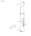
- a needle 1 is penetrated along the rotational shaft center from one end thereof such that the tip of the needle 1 reaches a communication hole corresponding to the mixed gas path.
- a pipe-shaped nozzle for fuel 2 reaches the communication hole and the tip of the needle 1 is inserted from the tip of the nozzle for fuel 2.
- the needle 1 and the nozzle for fuel 2 consist of a needle valve and the needle 1 shifts in the axial direction along with the rotation of the rotary valve to open and close a nozzle opening 3 provided with the nozzle for fuel 2.
- the flow of air is illustrated with an outlined arrow while the fuel is illustrated in misty form, respectively.
- Patent Document 1 Japanese Unexamined Patent Application Publication No. 2008-69767
- the purpose of the present invention is to provide a stratified scavenging two-cycle engine and a carburetor for said engine, capable of separating and supplying mixed gas and leading air without fail even in the case of using a small size carburetor comprising one intake path.
- the stratified scavenging two-cycle engine in the present invention is a stratified scavenging two-cycle engine comprising: an engine body provided with an intake port through which mixed gas flows in and an air port through which leading air flows in, a carburetor for generating said mixed gas and leading air in the intake path, provided with a pivotable rotary valve for switching the opening and closing of one intake path, and an insulator arranged between said engine body and carburetor, provided with a mixed gas path for circulating said mixed gas and an air path for circulating said leading air, wherein a nozzle opening for ejecting fuel opened outward from a rotary shaft center side is provided for the rotary valve, and a guide section by which fuel from the nozzle opening is guided to a position corresponding to a position upstream in the mixed gas path among the mixed gas path and the air path is provided for the nozzle opening.
- the insulator is provided with a partitioning section for partitioning the inside into the mixed gas path and the air path, while an extended projection provided integrally upstream of the partitioning section and extendedly projected in the intake path of the carburetor is ideally fit in the intake path.
- the rotary shaft center of the rotary valve and the shaft line of a cylinder of the engine body may perpendicularly be crossed or may also be parallel.
- the carburetor in the present invention is a carburetor comprising a body that includes one intake path and a pivotable rotary valve for switching the opening and closing of the intake path, wherein the rotary valve is provided with a nozzle opening for ejecting fuel outward from the rotary shaft center side and the nozzle opening is provided with a guide section by which fuel from the nozzle opening is guided to a prescribed position on the outward side.
- the guide section is preferably formed into a cylindrical shape.
- the fuel ejected from the nozzle opening may be favorably ejected upstream in the mixed gas path of an insulator by the guide section. Therefore, without mixing mixed gas containing the ejected fuel into an air path for leading air, said mixed gas is sucked straight into the engine body side through the mixed gas path ensuring separation and supplying of the mixed gas and leading air even when using a small size carburetor in which only one intake path is provided therein, making it possible to achieve the purpose of the present invention.
- the nozzle opening can be made downward allowing efficient suction of fuel onto the mixed gas path side by promptly ejecting said fuel downward using its own weight to improve output while ensuring separation from the air.
- each path within the insulator may be formed into a straightforward form, allowing a reduction in path resistance and preventing fuel from stagnantly remaining.
- Embodiment 1 of the present invention a two-cycle engine (from hereon, referred to as an engine) 10 pertaining to Embodiment 1 of the present invention is described.
- the engine 10 is a stratified scavenging two-cycle engine of a piston valve type and is configured comprising an engine body 11, a carburetor 12 for supplying mixed gas and leading air to the engine body 11, and an insulator 13 arranged between the engine body 11 and the carburetor 12 for blocking heat from the engine body 11 to the carburetor 12.
- a cylinder 14 is illustrated, with a crank case as well as a piston omitted from the illustration.
- an air port 17 for leading air is provided in the upper part of the intake port 15 for the cylinder 14.
- the air port 17 is closed for communication with respect to an air communication path provided at the outer peripheral surface of a piston. Furthermore, the air communication path of the piston is closed for communication with respect to a scavenging port 18 provided with the cylinder 14. These communicating and closing switching operations are performed by reciprocating movements of the piston.
- a piston functions as a valve for introducing leading air and the leading air is transported into the scavenging port 18 via the air port 17 through the air communication path on the outer periphery of the piston at the timing when mixed gas is guided into the crack case.
- the carburetor 12 is traditionally used for a normal two-cycle engine instead of a stratified scavenging two-cycle engine, with one intake path 21 provided in a body 19. Furthermore, the body 19 is provided with a pivotable rotary valve 22 penetrating an intake path 21. A communication hole 23 is provided with the rotary valve 22 for communication between the upstream and the downstream of the intake path 21, switching opening and closing of the intake path 21 via the communication hole 23 according to the rotating position of the rotary valve 22. It should be noted that Fig. 1 shows a state in which the rotary valve 22 is completely open.
- the carburetor 23 is arranged in a direction into which a rotary shaft center C1 of the rotary valve 22 perpendicularly crosses a shaft line C2 of the cylinder 14.
- a purge pump, etc. not illustrated but provided in the carburetor 12 ends up being in a side position with respect to the cylinder 14.
- a needle 24 or a nozzle for fuel 25 are shown as a cross-section along the radial direction.
- the needle 24 and the nozzle for fuel 25 in the state of Fig. 1 are enlarged and shown in Fig. 2 and Fig. 3 .
- a nozzle opening 26 provided with the nozzle for fuel 25 is opened downward in the figure. That is, fuel to be withdrawn from the nozzle opening 26 is output in a direction perpendicularly crossing with respect to the direction of suction flow from the rotary shaft center C1 side, specifically, downward in the figure within the communication hole 23 of the rotary valve 22.
- a guide section 26A internally accommodating the nozzle opening 26 is provided with the nozzle for fuel 25.
- the guide section 26A is cylindrically formed and the tip end thereof opens to a position corresponding to a position upstream in a mixed gas path 27. Therefore, fuel output from the nozzle opening 26 is ejected to the position corresponding to a position upstream in the mixed gas path 27 to be described later by the guide section 26A provided with the nozzle opening 26.
- the length of said guide section 26A is set long within a range without interfering with the rotation of the rotary valve 22, ensuring the fuel is guided without fail.
- the fuel ejected from the guide section 26A is generated as mixed gas by mixing with air and the mixed gas is sucked toward the intake port 15 of the cylinder 14.
- the fuel is not ejected to the upper side in the communication hole 23
- air passing the upper side thereof is generated as leading air without containing fuel and is sucked into the air port 17 of the cylinder 14.
- the rotary valve 22 indicated by a dashed two-dotted line is at a position in which the engine 10 is in an idling state. Air passing through the rotary valve 22 flows into the communication hole 23 from the upper side of the intake path 21, descends within the communication hole 23, and flows out from the lower side of the intake path 21. Therefore, the direction of air descending in the communication hole 23 is approximately the same as the direction of the fuel being guided by the guide section 26A, as shown by an arrow in Fig. 1 .
- the insulator 13 is made from synthetic resin having heat insulating performance comprising a mixed gas path 27 on the lower side communicating with the intake port 15 of the cylinder 14 and an air path 28 on the upper side communicating with the air port 17 respectively on the downstream side.
- the upstream side of the mixed gas path 27 openly communicates corresponding to the lower side of the intake path 21 of the carburetor 12, while the upstream side of the air path 28 openly communicates corresponding to the upper side of the intake path 21.
- Each of the paths 27 and 28 within the insulator 13 are partitioned vertically by a partitioning section 29.
- the partitioning section 29 is formed into a plate shape by a flat face.
- the upstream side of the partitioning section 29 is provided with an extended projection 31 extendedly projecting in the intake path 21 of the carburetor 12 to the rotary valve 22.
- a tip end rim 31A of the extended projection 31 is parallel to a rotary shaft center C1 of the rotary valve 22 and also positioned at the same height in the figure.
- the connecting portion of the partitioning section 29 and the extended projection 31 is the same.
- the extended projection 31 is formed into a flat plate shape with the width W formed to be the same as the internal diameter of the intake path 21. Due to the extended projection 31, a portion on the downstream side within the intake path 21 is divided vertically into a mixed gas side and a leading air side without leaving any gaps to prevent mixed gas from flowing into the air path 28 side of the insulator 13.
- the width W of the extended projection 31 may be made slightly larger than the internal diameter of the intake path 21 such that both ends widthwise of the extended projection 31 engage with a notch corresponding to inside the intake path 21 and, in such a case, the position of the extended projection 31 within the intake path 21 may be determined with greater assurance.
- the insulator 13 is provided with a negative pressure transmission path 32 for transmitting negative pressure on the engine body 11 side to the carburetor 12 side and one end thereof communicates with a negative pressure output hole 33 ( Fig. 1 ) of the cylinder 14 while the other end communicates with a negative pressure input hole of the carburetor 12 omitted from the illustration via a communication groove 35 provided on a carburetor mounting face 34.
- the negative pressure guided to the carburetor 12 is used to operate a diaphragm, etc. that functions as a fuel pump in the carburetor 12.
- insertion holes 36 at the four corners of the insulator 13 are holes for inserting bolts which are used to secure the insulator 13 to the cylinder 14, and a vertical pair of screw holes 37 are holes for bolts to be screwed in order to secure the carburetor 12 to the insulator 13.
- the rotary shaft center C1 of the rotary valve 22 of the carburetor 12 perpendicularly crosses the shaft line C2 of the cylinder 14 and, in the communication hole 23 of the rotary valve 22, the nozzle opening 26 is opened downward corresponding to the intake port 15 on the lower side.
- the tip of the guide section 26A provided with the nozzle opening 26 opened at a position corresponding to a position upstream in the mixed gas path 27.
- the fuel from the nozzle opening 26 is guided to the position corresponding to a position upstream in the mixed gas path 27 by the guide section 26A, and may be transported without fail straight to the intake port 15 through the mixed gas path 27 on the lower side preventing the mixed gas from flowing into the air path 28 side. Therefore, as carburetor 12, a small one comprising only one intake path 21 may be used, allowing the engine 10 to be downsized.
- the fuel may efficiently be withdrawn from the guide section 26A, making it possible to stabilize the number of engine rotations by stably supplying fuel even in an idling state with little air flow.
- the engine 10 pertaining to Embodiment 2 of the present invention is shown in Fig. 6 and Fig. 7 .
- the carburetor 12 is arranged such that the rotary shaft center C1 of the rotary valve 22 becomes parallel to the shaft line C2 of the cylinder 14. Therefore, as shown in the enlarged drawing in Fig. 8 , the tip end of the guide section 26A opens at a position corresponding to a position upstream in the mixed gas path 27 in the communication hole 23 of the rotary valve 22, while mixed gas is generated from the ejected fuel guided by the guide section 26A and air passing the upstream in the mixed gas path 27. During this event, a purge pump 38 provided with the carburetor 12 comes to a position on the lower side.
- leading air with no presence of fuel is generated in the upstream side of the air path 28. That is, in the present embodiment, the position at which the mixed gas is generated and the position at which the leading air is generated in the intake path 21 of the carburetor 12 are significantly different from Embodiment 1.
- the shape of the partitioning section 29 and the extended projection 31 in the insulator 13 to be used in the present embodiment is also significantly different from the previous Embodiment 1. That is, given the fact that the engine body 11 is the same both in the present embodiment and Embodiment 1 as well as the position of the intake port 15 and the position of the air port 17 in the cylinder 14, for the purpose of transporting the mixed gas or the leading air generated at different positions within the carburetor 12 to each of the ports 15 and 17, the partitioning section 29 and the extended projection 31 (a shape of each of the paths 27, 28) are formed into a shape corresponding to the generated position.
- the partitioning section 29 and the extended projection 31 are formed into a curve approaching, in parallel, the rotary shaft center C1 on the carburetor 12 side heading upstream and also formed so as to vertically divide each of the paths 27 and 28 heading downstream by dividing each of the paths 27 and 28 into left and right.
- the mixed gas path 27 opens on the right side in the drawing
- the air path 28 opens on the left side in the drawings.
- the guide member 26A opens at a position corresponding to a position upstream in the mixed gas path 27 on the right side. Therefore, likewise, the fuel from the nozzle opening 26 having been guided by the guide section 26A is ejected to a position corresponding to a position upstream in the mixed gas path 27.
- the present invention is not limited to each of the previous embodiments and modification examples within the scope in which the purpose of the present invention may be achieved are included in the present invention.
- the carburetor 12 in the previous Embodiment 1 is mounted such that the rotary shaft center C 1 of the rotary vale 22 perpendicularly crosses the shaft line C2 of the cylinder 14 and the carburetor 12 in Embodiment 2 is mounted such that the rotary shaft center C1 of the rotary valve 22 comes to parallel the shaft line C2 of the cylinder 14; however, the relationship between the rotary shaft center C1 and the shaft line C2 is arbitrary and it is also possible to mount said carburetor so as to cross an angle other than 90°.
- the partitioning section 29 or the extended projection 31 of the insulator 13 may also be provided so as to perpendicularly cross the rotary shaft center C 1 and the shaft line C2.
- the partitioning section 29 or the extended projection 31 may also be provided so as to perpendicularly cross the rotary shaft center C 1 and the shaft line C2.
- fuel from the nozzle 26 may be guided to a position corresponding to a position upstream in the mixed gas path 27 to be ejected therefrom.
- Embodiment 1 the same action effect as in Embodiment 1 may be obtained to achieve the purpose of the present invention without vertically shifting the positional relationship of the nozzle opening 26 and the partitioning section 29 or the extended section 31.
- the guide section 26A was a cylindrical shape, but said guide section may also be a tongue-shape or a U-shaped cross-section, without being limited to the former as long as the fuel output from the nozzle opening 26 can be guided to a position corresponding to a position upstream in the mixed gas path 27.
- the present invention may favorably be applied to a piston valve-type or a lead-valve type stratified scavenging two-cycle engine.
Landscapes
- Engineering & Computer Science (AREA)
- Chemical & Material Sciences (AREA)
- Combustion & Propulsion (AREA)
- Mechanical Engineering (AREA)
- General Engineering & Computer Science (AREA)
- Control Of Throttle Valves Provided In The Intake System Or In The Exhaust System (AREA)
- Combustion Methods Of Internal-Combustion Engines (AREA)
Applications Claiming Priority (1)
| Application Number | Priority Date | Filing Date | Title |
|---|---|---|---|
| PCT/JP2009/068126 WO2011048673A1 (fr) | 2009-10-21 | 2009-10-21 | Moteur à deux temps à balayage stratifié et carburateur |
Publications (1)
| Publication Number | Publication Date |
|---|---|
| EP2492486A1 true EP2492486A1 (fr) | 2012-08-29 |
Family
ID=43899920
Family Applications (1)
| Application Number | Title | Priority Date | Filing Date |
|---|---|---|---|
| EP09850571A Withdrawn EP2492486A1 (fr) | 2009-10-21 | 2009-10-21 | Moteur à deux temps à balayage stratifié et carburateur |
Country Status (5)
| Country | Link |
|---|---|
| US (1) | US20120240907A1 (fr) |
| EP (1) | EP2492486A1 (fr) |
| JP (1) | JPWO2011048673A1 (fr) |
| CN (1) | CN102575618A (fr) |
| WO (1) | WO2011048673A1 (fr) |
Cited By (2)
| Publication number | Priority date | Publication date | Assignee | Title |
|---|---|---|---|---|
| EP2860382A1 (fr) * | 2013-10-10 | 2015-04-15 | Yamabiko Corporation | Carburateur rotatif |
| US9938948B2 (en) | 2013-10-10 | 2018-04-10 | Continental Automotive Gmbh | Fluid injection assembly for a combustion engine |
Families Citing this family (3)
| Publication number | Priority date | Publication date | Assignee | Title |
|---|---|---|---|---|
| JPWO2011048674A1 (ja) * | 2009-10-21 | 2013-03-07 | ハスクバーナ・ゼノア株式会社 | 層状掃気2サイクルエンジン |
| JP6608676B2 (ja) | 2015-11-10 | 2019-11-20 | 株式会社やまびこ | 2ストローク内燃エンジン用のロータリー式気化器 |
| US12435689B2 (en) | 2023-01-19 | 2025-10-07 | Northwest Uld, Inc. | Engine with diverter for heavy fuel injection |
Family Cites Families (15)
| Publication number | Priority date | Publication date | Assignee | Title |
|---|---|---|---|---|
| US6257179B1 (en) * | 1999-04-28 | 2001-07-10 | Mitsubishi Heavy Industries, Ltd. | Two-stroke cycle engine |
| JP3728156B2 (ja) * | 1999-10-21 | 2005-12-21 | 株式会社日本ウォルブロー | 2行程機関の加速装置 |
| JP2001295652A (ja) * | 2000-04-13 | 2001-10-26 | Zama Japan Kk | 層状掃気2サイクルエンジン |
| JP4081245B2 (ja) * | 2001-04-13 | 2008-04-23 | 株式会社共立 | 燃料噴射装置及びそれを備えた混合気生成装置 |
| JP2003097276A (ja) * | 2001-09-27 | 2003-04-03 | Zama Japan Kk | 層状掃気2サイクルエンジンの掃気用空気・混合気制御装置 |
| US6585235B2 (en) * | 2001-10-11 | 2003-07-01 | Walbro Corporation | Fuel regulating mechanism and method for a rotary throttle valve type carburetor |
| US6769670B2 (en) * | 2001-12-07 | 2004-08-03 | Walbro Japan, Inc. | Starting assembly for a carburetor |
| US6901892B2 (en) * | 2002-08-03 | 2005-06-07 | Nagesh S. Mavinahally | Two stroke engine with rotatably modulated gas passage |
| JP2005002887A (ja) * | 2003-06-12 | 2005-01-06 | Walbro Japan Inc | ロータリースロットバルブ式気化器 |
| US7093570B2 (en) * | 2003-12-31 | 2006-08-22 | Nagesh S Mavinahally | Stratified scavenged two-stroke engine |
| US20060243230A1 (en) * | 2005-03-23 | 2006-11-02 | Mavinahally Nagesh S | Two-stroke engine |
| US7325791B2 (en) * | 2005-09-15 | 2008-02-05 | Zama Japan Co., Ltd. | Carburetor for stratified scavenging two-cycle engine |
| JP2007239463A (ja) * | 2006-03-03 | 2007-09-20 | Komatsu Zenoah Co | 2サイクルエンジン |
| JP2008069767A (ja) | 2006-08-17 | 2008-03-27 | Walbro Japan Inc | 層状掃気用気化器 |
| JP4696058B2 (ja) * | 2006-12-27 | 2011-06-08 | ザマ・ジャパン株式会社 | 層状掃気エンジン用2ボアロータリ気化器のロータ内形状 |
-
2009
- 2009-10-21 US US13/503,110 patent/US20120240907A1/en not_active Abandoned
- 2009-10-21 WO PCT/JP2009/068126 patent/WO2011048673A1/fr not_active Ceased
- 2009-10-21 JP JP2011537054A patent/JPWO2011048673A1/ja active Pending
- 2009-10-21 EP EP09850571A patent/EP2492486A1/fr not_active Withdrawn
- 2009-10-21 CN CN2009801620615A patent/CN102575618A/zh active Pending
Non-Patent Citations (1)
| Title |
|---|
| See references of WO2011048673A1 * |
Cited By (3)
| Publication number | Priority date | Publication date | Assignee | Title |
|---|---|---|---|---|
| EP2860382A1 (fr) * | 2013-10-10 | 2015-04-15 | Yamabiko Corporation | Carburateur rotatif |
| US9422890B2 (en) | 2013-10-10 | 2016-08-23 | Yamabiko Corporation | Rotary carburetor |
| US9938948B2 (en) | 2013-10-10 | 2018-04-10 | Continental Automotive Gmbh | Fluid injection assembly for a combustion engine |
Also Published As
| Publication number | Publication date |
|---|---|
| CN102575618A (zh) | 2012-07-11 |
| US20120240907A1 (en) | 2012-09-27 |
| JPWO2011048673A1 (ja) | 2013-03-07 |
| WO2011048673A1 (fr) | 2011-04-28 |
Similar Documents
| Publication | Publication Date | Title |
|---|---|---|
| US7637244B2 (en) | Intake air amount controlling apparatus for an internal-combustion engine | |
| CN101395355A (zh) | 二冲程发动机 | |
| US10550804B2 (en) | Air intake apparatus of multi-cylinder engine having secondary gas inlet passage connected to intake air inlet passage | |
| EP2492486A1 (fr) | Moteur à deux temps à balayage stratifié et carburateur | |
| US8677967B2 (en) | Intake manifold having negative pressure relief | |
| CN103047056B (zh) | 发动机的进气装置 | |
| EP2947305B1 (fr) | Moteur à combustion interne à deux temps à balayage stratifié | |
| US20100037853A1 (en) | Intake system for an internal combustion engine | |
| US20150337764A1 (en) | Carburetor For Stratified Scavenging Two-Stroke Engine | |
| CN104879239B (zh) | 旋转式化油器 | |
| EP2492468A1 (fr) | Moteur à deux temps à balayage stratifié | |
| CN101131136B (zh) | 分层扫气化油器 | |
| US9988971B2 (en) | Air leading type two-stroke engine and intake system for same, and carburetor | |
| CN104564428B (zh) | 旋转式化油器 | |
| CN203081566U (zh) | 二冲程发动机 | |
| CN105464841B (zh) | 化油器 | |
| CN102884304B (zh) | 二冲程发动机中的空气过滤器 | |
| JP5396290B2 (ja) | 2サイクルエンジン | |
| US20090218534A1 (en) | Carburettors | |
| JP5690903B2 (ja) | 2サイクルエンジン | |
| JP2008163770A (ja) | 気化器の低速燃料通路 |
Legal Events
| Date | Code | Title | Description |
|---|---|---|---|
| PUAI | Public reference made under article 153(3) epc to a published international application that has entered the european phase |
Free format text: ORIGINAL CODE: 0009012 |
|
| 17P | Request for examination filed |
Effective date: 20120327 |
|
| AK | Designated contracting states |
Kind code of ref document: A1 Designated state(s): AT BE BG CH CY CZ DE DK EE ES FI FR GB GR HR HU IE IS IT LI LT LU LV MC MK MT NL NO PL PT RO SE SI SK SM TR |
|
| DAX | Request for extension of the european patent (deleted) | ||
| STAA | Information on the status of an ep patent application or granted ep patent |
Free format text: STATUS: THE APPLICATION IS DEEMED TO BE WITHDRAWN |
|
| 18D | Application deemed to be withdrawn |
Effective date: 20140501 |