EP2492436A2 - Installation for blocking the passage of persons - Google Patents
Installation for blocking the passage of persons Download PDFInfo
- Publication number
- EP2492436A2 EP2492436A2 EP20120154363 EP12154363A EP2492436A2 EP 2492436 A2 EP2492436 A2 EP 2492436A2 EP 20120154363 EP20120154363 EP 20120154363 EP 12154363 A EP12154363 A EP 12154363A EP 2492436 A2 EP2492436 A2 EP 2492436A2
- Authority
- EP
- European Patent Office
- Prior art keywords
- installation according
- closing device
- locking device
- closing
- installation
- Prior art date
- Legal status (The legal status is an assumption and is not a legal conclusion. Google has not performed a legal analysis and makes no representation as to the accuracy of the status listed.)
- Granted
Links
Images
Classifications
-
- E—FIXED CONSTRUCTIONS
- E06—DOORS, WINDOWS, SHUTTERS, OR ROLLER BLINDS IN GENERAL; LADDERS
- E06B—FIXED OR MOVABLE CLOSURES FOR OPENINGS IN BUILDINGS, VEHICLES, FENCES OR LIKE ENCLOSURES IN GENERAL, e.g. DOORS, WINDOWS, BLINDS, GATES
- E06B11/00—Means for allowing passage through fences, barriers or the like, e.g. stiles
- E06B11/08—Turnstiles; Gates for control of entry or exit of persons, e.g. in supermarkets
- E06B11/085—Turnstiles; Gates for control of entry or exit of persons, e.g. in supermarkets non-rotary or with a limited angle of rotation, e.g. 90°
Definitions
- the invention relates to a system for closing a person passage with the features in the preamble of the main claim.
- the object of the invention is thus to show an improved system for closing a person passage.
- the invention solves the problem with the features in the main claim.
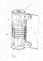
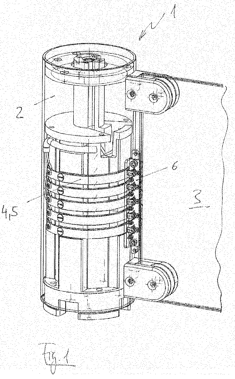
- the invention relates to a system 1 for closing a passenger passage 5 with at least one carrier 2 and a closing device 3.
- the closing device 3 is pivotally and / or rotatably arranged on the carrier 2. It is possible to pass on energy and / or information contact-free and / or contact-related to the locking device 3.
- a slip ring contact 4 is used.
- the slip ring contact 4 may have two or more rings 5. As in FIG. 1 shown, a number of five rings has been found to be advantageous.
- the rings are formed of copper and arranged on the carrier 2. They preferably have a width of about one cm.
- sliding contacts 6 are attached to the locking device 3, which are permanently spring-loaded.
- the energy can be used to e.g. to illuminate the locking device 3 or attach a display that requires energy.
- a display that requires energy.
- it could be a warning sign, a directional sign, or a warning.
- changing offers or greetings could be attached to the locking device 3.
- locking device 3 a swivel bracket made of glass.
- a closing device 3 one or two swivel bracket can be used.
- Edge lighting achieves advantageous illumination of the closure device 3.
- Other materials which produce the same or a similar effect are left to the person skilled in the art.
- such a swivel bracket can be backlit glass.
- the locking device has 3 LEDs.
- a frame is attached to the locking device 3. This can be provided along the entire circumference of the closing device 3, or only at the upper and / or lower edge.
- the frame should be arranged stationarily on the closing device 3. An adhesive bond has proven to be advantageous.
- the frame offers the possibility to provide 3 LEDs between this and the locking device.
- the locking device 3 can be backlit.
- the closing device 3 formed from glass can itself display, motifs or logos, e.g. sandblasted have formed.
- RGB or cathode cold light lamps could also be used.
- the locking device 3 In addition to energy and information from the system 1 to the locking device 3 can be passed. It may be data and / or signals, such as a serial protocol for a display described above or a standard interface such as HDMI.
- the opening and closing of the locking device 3 via radar has proved to be advantageous and is known from the prior art. It would be conceivable to equip the locking device 3 with an additional antenna, which is arranged around the locking device 3.
- an RFID reader is provided in the closing device 3, which records access data without contact, forwards it to the system 1 and releases the passage or keeps it closed.
- the locking device 3 could be provided by means of sensors, e.g. capacitive, detect people in the passage and send a stop request to the system 1. The locking device 3 would then stop immediately and persons, e.g. a child, protect from injury.
- sensors e.g. capacitive
Landscapes
- Engineering & Computer Science (AREA)
- Civil Engineering (AREA)
- Structural Engineering (AREA)
- Power-Operated Mechanisms For Wings (AREA)
- Lock And Its Accessories (AREA)
- Refuge Islands, Traffic Blockers, Or Guard Fence (AREA)
- Burglar Alarm Systems (AREA)
Abstract
Die Erfindung betrifft Anlage (1) Anlage (1) zum Verschließen eines Personendurchgangs, mit wenigstens einem Träger (2) und einer Schließeinrichtung (3), wobei die Schließeinrichtung (3) schwenkbar und/oder drehbar am Träger (2) angeordnet ist.The invention relates to a system (1) for closing a passageway with at least one support (2) and a locking device (3), wherein the locking device (3) is pivotally and / or rotatably mounted on the support (2).
Die Erfindung zeichnet sich dadurch aus, dass Energie und/oder Informationen kontaktfrei und/oder kontaktbehaftet an die Schließeinrichtung (3) weitergegeben werden.
Description
Die Erfindung betrifft eine Anlage zum Verschließen eines Personendurchgangs mit den Merkmalen im Oberbegriff des Hauptanspruchs.The invention relates to a system for closing a person passage with the features in the preamble of the main claim.
Solche Anlagen sind aus dem Stand der Technik bekannt. Die
Ausgehend von diesem Stand der Technik, kam es zu der Anforderung die Schließeinrichtung einer solchen Anlage mit Energie oder Informationen zu versorgen.Based on this prior art, it came to the requirement to provide the closing device of such a system with energy or information.
Herkömmlicherweise würde man hierfür Kabel verwenden. Diese würden jedoch gerade bei den hier verwendeten beweglichen Teilen störend wirken.Conventionally, one would use cables for this purpose. However, these would be disturbing especially for the moving parts used here.
Die Aufgabe der Erfindung besteht somit darin, eine verbesserte Anlage zum Verschließen eines Personendurchgangs aufzuzeigen.The object of the invention is thus to show an improved system for closing a person passage.
Die Erfindung löst die Aufgabe mit den Merkmalen im Hauptanspruch.The invention solves the problem with the features in the main claim.
Eine Übertragung von Energie oder Informationen ist dauerhaft auf einfache Art und Weise möglich. Kabel sind hierfür keine mehr erforderlich.A transfer of energy or information is permanently possible in a simple manner. Cables are no longer necessary for this.
Die Erfindung wird anhand von Ausführungsbeispielen näher erläutert. Es zeigt
-
Fig. 1 ausschnittsweise eine Anlage zum Verschließen einen Personendurchgangs mit Träger, Schließeinrichtung in 3-D-Darstellung.
-
Fig. 1 partial view of a system for closing a pedestrian passage with carrier, locking device in 3-D representation.
Die Erfindung betrifft eine Anlage 1 zum Verschließen eines Personendurchgangs 5 mit wenigstens einem Träger 2 und einer Schließeinrichtung 3. Die Schließeinrichtung 3 ist schwenkbar und/oder drehbar am Träger 2 angeordnet. Es besteht die Möglichkeit, Energie und/oder Informationen kontaktfrei und/oder kontaktbehaftet an die Schließeinrichtung 3 weiterzugeben. Hierfür findet eine Schleifringkontaktierung 4 Einsatz. Die Schleifringkontaktierung 4 kann zwei oder mehr Ringen 5 aufweisen. Wie in
Durch diese Schleifringkontaktierung 4 ist eine Übertragung von Energie und Informationen von dem Träger 3 in die Schließeinrichtung 3 dauerhaft möglich. Die Schleifringkontaktierung 4 ist verdeckt, so dass das Eindringen von Schmutz oder Feuchtigkeit verhindert werden kann.Through this slip ring contacting 4 a transfer of energy and information from the carrier 3 in the locking device 3 is permanently possible. The slip ring contact 4 is covered, so that the ingress of dirt or moisture can be prevented.
Die Energie kann verwendet werden, um z.B. die Schließeinrichtung 3 zu beleuchten oder ein Display anzubringen, das Energie benötigt. Es könnte beispielsweise um ein Warnschild, ein Schild mit einer Richtungsangabe oder einem Warnhinweis sein. Auch könnten wechselnde Angebote oder Begrüßungstexte an der Schließeinrichtung 3 angebracht werden.The energy can be used to e.g. to illuminate the locking device 3 or attach a display that requires energy. For example, it could be a warning sign, a directional sign, or a warning. Also, changing offers or greetings could be attached to the locking device 3.
Auch bietet sich die Möglichkeit, als Schließeinrichtung 3 einen Schwenkbügel aus Glas zu verwenden. Hierbei können als Schließeinrichtung 3 ein oder zwei Schwenkbügel verwendet werden.Also offers the possibility to use as locking device 3 a swivel bracket made of glass. Here, as a closing device 3, one or two swivel bracket can be used.
Eine Kantenbeleuchtung erzielt eine vorteilhafte Beleuchtung der Schließeinrichtung 3. Andere Materialien, die den gleichen oder einen ähnlichen Effekt bewirken, bleiben dem Fachmann überlassen.Edge lighting achieves advantageous illumination of the closure device 3. Other materials which produce the same or a similar effect are left to the person skilled in the art.
Hierbei kann ein solcher Schwenkbügel aus Glas hinterleuchtet sein. Um dies auf einfache und energiesparende Art und Weise zu ermöglichen, bietet es sich an, dass die Schließeinrichtung 3 LEDs aufweist.In this case, such a swivel bracket can be backlit glass. To make this possible in a simple and energy-saving manner, it makes sense that the locking device has 3 LEDs.
Vorzugsweise ist an der Schließeinrichtung 3 ein Rahmen angebracht. Dieser kann entlang des kompletten Umfangs der Schließeinrichtung 3 vorgesehen sein, oder nur am oberen und/oder unteren Rand. Der Rahmen sollte ortsfest an der Schließeinrichtung 3 angeordnet sein. Eine Klebverbindung hat sich als vorteilhaft erwiesen. Der Rahmen bietet die Möglichkeit, zwischen diesem und der Schließeinrichtung 3 LEDs vorzusehen. Somit kann die Schließeinrichtung 3 hinterleuchtet werden.Preferably, a frame is attached to the locking device 3. This can be provided along the entire circumference of the closing device 3, or only at the upper and / or lower edge. The frame should be arranged stationarily on the closing device 3. An adhesive bond has proven to be advantageous. The frame offers the possibility to provide 3 LEDs between this and the locking device. Thus, the locking device 3 can be backlit.
Es ist denkbar, verschiedene Farben einzusetzen, z.B. die Farbe Rot, wenn die Schließeinrichtung 3 geschlossen ist und die Farbe Grün, sobald die Schließeinrichtung 3 freigegeben ist. Auch bei Störung der Anlage könnte eine spezielle Farbe eingesetzt werden. Ferner könnte ein Blinken in einer bestimmten Farbe, die Aufmerksamkeit erwecken.It is conceivable to use different colors, e.g. the color red when the locking device 3 is closed and the color green when the locking device 3 is released. Even if the system malfunctions, a special color could be used. Furthermore, blinking in a particular color could attract attention.
In einer weiterführenden Ausführung kann die aus Glas gebildete Schließeinrichtung 3 selbst Anzeigen, Motive oder Logos z.B. sandgestrahlt ausgebildet haben.In a further embodiment, the closing device 3 formed from glass can itself display, motifs or logos, e.g. sandblasted have formed.
Anstelle von LEDs könnten ferner RGBs oder Kathodenkaltlichtlampen verwendet werden.Instead of LEDs, RGB or cathode cold light lamps could also be used.
Neben Energie können auch Informationen von der Anlage 1 an die Schließeinrichtung 3 weitergegeben werden. Es können Daten und/oder Signale sein, wie z.B. ein serielles Protokoll für ein oben beschriebenes Display oder eine Standard-Schnittstelle wie HDMI.In addition to energy and information from the system 1 to the locking device 3 can be passed. It may be data and / or signals, such as a serial protocol for a display described above or a standard interface such as HDMI.
Das Öffnen und Schließen der Schließeinrichtung 3 über Radar hat sich als vorteilhaft erwiesen und ist aus dem Stand der Technik bekannt. Es wäre denkbar, die Schließeinrichtung 3 mit einer zusätzlichen Antenne auszustatten, der um die Schließeinrichtung 3 angeordnet ist.The opening and closing of the locking device 3 via radar has proved to be advantageous and is known from the prior art. It would be conceivable to equip the locking device 3 with an additional antenna, which is arranged around the locking device 3.
In einer weiterführenden Variante ist ein RFID-Reader in der Schließeinrichtung 3 vorgesehen, der kontaktlos Zugangsdaten erfasst, an die Anlage 1 weitergibt und den Durchgang freigibt oder weiterhin verschlossen lässt.In a further variant, an RFID reader is provided in the closing device 3, which records access data without contact, forwards it to the system 1 and releases the passage or keeps it closed.
Ferner könnte die Schließeinrichtung 3 mittels Sensoren, z.B. kapazitiv, Personen im Durchgang erkennen und eine Stopp-Anforderung an die Anlage 1 senden. Die Schließeinrichtung 3 würde dann unverzüglich stoppen und Personen, z.B. ein Kind, vor Verletzungen schützen.Furthermore, the locking device 3 could be provided by means of sensors, e.g. capacitive, detect people in the passage and send a stop request to the system 1. The locking device 3 would then stop immediately and persons, e.g. a child, protect from injury.
- 11
- Anlageinvestment
- 22
- Trägercarrier
- 33
- Schließeinrichtungclosing device
- 44
- SchleifringkontaktierungSchleifringkontaktierung
- 55
- Ringring
- 66
- Gleitkontaktsliding contact
Claims (10)
Priority Applications (1)
| Application Number | Priority Date | Filing Date | Title |
|---|---|---|---|
| PL12154363T PL2492436T3 (en) | 2011-02-24 | 2012-02-08 | Installation for blocking the passage of persons |
Applications Claiming Priority (1)
| Application Number | Priority Date | Filing Date | Title |
|---|---|---|---|
| DE102011012341A DE102011012341A1 (en) | 2011-02-24 | 2011-02-24 | Installation for closing a person's handrail |
Publications (3)
| Publication Number | Publication Date |
|---|---|
| EP2492436A2 true EP2492436A2 (en) | 2012-08-29 |
| EP2492436A3 EP2492436A3 (en) | 2014-06-18 |
| EP2492436B1 EP2492436B1 (en) | 2016-01-13 |
Family
ID=45607626
Family Applications (1)
| Application Number | Title | Priority Date | Filing Date |
|---|---|---|---|
| EP12154363.1A Active EP2492436B1 (en) | 2011-02-24 | 2012-02-08 | Installation for blocking the passage of persons |
Country Status (3)
| Country | Link |
|---|---|
| EP (1) | EP2492436B1 (en) |
| DE (1) | DE102011012341A1 (en) |
| PL (1) | PL2492436T3 (en) |
Families Citing this family (4)
| Publication number | Priority date | Publication date | Assignee | Title |
|---|---|---|---|---|
| DE202020005292U1 (en) | 2020-12-22 | 2021-01-21 | Koco Motion Gmbh | Passage lock |
| DE102020007871A1 (en) | 2020-12-22 | 2022-06-23 | Koco Motion Gmbh | passage lock |
| DE202022001993U1 (en) | 2022-09-09 | 2022-11-07 | Koco Motion Gmbh | passage lock |
| DE102022003309A1 (en) | 2022-09-09 | 2024-03-14 | Koco Motion Gmbh | Passage lock |
Citations (4)
| Publication number | Priority date | Publication date | Assignee | Title |
|---|---|---|---|---|
| EP0617188A1 (en) | 1993-03-20 | 1994-09-28 | Wanzl GmbH & Co. Entwicklungs-KG | Swinging door for a gateway |
| EP1031701B1 (en) | 1999-02-15 | 2003-05-07 | Wanzl Metallwarenfabrik Gmbh | Swing door |
| EP0995006B1 (en) | 1998-05-05 | 2003-06-11 | Wanzl Metallwarenfabrik Gmbh | Turnstile for the passage of people |
| DE19857206B4 (en) | 1998-12-11 | 2008-10-16 | Wanzl Metallwarenfabrik Gmbh | Swing door for a person passage |
Family Cites Families (3)
| Publication number | Priority date | Publication date | Assignee | Title |
|---|---|---|---|---|
| DE9109149U1 (en) * | 1991-07-24 | 1991-12-19 | Brüder Siegel GmbH & Co KG Draht- und Metallwarenfabrik, 8874 Leipheim | Customer guidance system for self-service stores, hardware stores, airports and the like |
| DE102007023360A1 (en) * | 2007-05-18 | 2008-11-27 | Wanzl Metallwarenfabrik Gmbh | Plant for closing a pedestrian passage |
| DE102008010671A1 (en) * | 2008-02-22 | 2009-11-19 | Goos, Jürgen, Prof. | Swing door for person passage system, has drive and guide modules fastened to front wall of supporting element such that drive and guide modules are aligned vertically with one another, where front wall is extended between side walls |
-
2011
- 2011-02-24 DE DE102011012341A patent/DE102011012341A1/en active Pending
-
2012
- 2012-02-08 PL PL12154363T patent/PL2492436T3/en unknown
- 2012-02-08 EP EP12154363.1A patent/EP2492436B1/en active Active
Patent Citations (4)
| Publication number | Priority date | Publication date | Assignee | Title |
|---|---|---|---|---|
| EP0617188A1 (en) | 1993-03-20 | 1994-09-28 | Wanzl GmbH & Co. Entwicklungs-KG | Swinging door for a gateway |
| EP0995006B1 (en) | 1998-05-05 | 2003-06-11 | Wanzl Metallwarenfabrik Gmbh | Turnstile for the passage of people |
| DE19857206B4 (en) | 1998-12-11 | 2008-10-16 | Wanzl Metallwarenfabrik Gmbh | Swing door for a person passage |
| EP1031701B1 (en) | 1999-02-15 | 2003-05-07 | Wanzl Metallwarenfabrik Gmbh | Swing door |
Also Published As
| Publication number | Publication date |
|---|---|
| DE102011012341A1 (en) | 2012-08-30 |
| EP2492436A3 (en) | 2014-06-18 |
| EP2492436B1 (en) | 2016-01-13 |
| PL2492436T3 (en) | 2016-05-31 |
Similar Documents
| Publication | Publication Date | Title |
|---|---|---|
| EP2717235B1 (en) | Access control device for persons in the form of a turnstile | |
| EP2492436B1 (en) | Installation for blocking the passage of persons | |
| EP2566723A1 (en) | Luminous finger-protection apparatus for a door of a vehicle and production method for a protective strip for a luminous finger-protection apparatus | |
| DE60201353T2 (en) | IMPROVED DISPLAY ELEMENT | |
| EP3121362A1 (en) | Door, especially a garage door | |
| WO2010097304A1 (en) | Security lock control device for an access system and access system | |
| EP3243197B1 (en) | Method for displaying information for passengers in the floor region of a vehicle for transporting people | |
| DE102014206074B4 (en) | Lamppost | |
| DE102009046208B4 (en) | Cooking appliance door | |
| EP0884265B1 (en) | Indicating device for elevators | |
| DE202012101180U1 (en) | blocking element | |
| EP4051520B1 (en) | Door panel with a illumination profile for a vehicle | |
| WO2022167218A1 (en) | Method and device for visualising changeable visual information for passengers of a vehicle | |
| DE102015005639A1 (en) | Communication device with a stationary reader, and a method for operating such a communication device | |
| DE102023004745A1 (en) | Door device of a rail vehicle with visualization device and rail vehicle with the door device | |
| DE102010055794B4 (en) | stocker | |
| EP2597634B1 (en) | Display device | |
| DE102018006956B4 (en) | Display device and motor vehicle with such a display device | |
| DE202016007645U1 (en) | Light signal vest | |
| DE29621999U1 (en) | Shut-off device with a bollard that can be lowered into a recess | |
| DE202023001440U1 (en) | Name plate glass for door intercom systems with NFC e-Paper labeling and lighting | |
| DE102023121782A1 (en) | escape route safety device with status display | |
| EP1818256B1 (en) | Aircraft, in particular helicopter | |
| EP4658600A1 (en) | Guideway device with electronic reproduction means | |
| DE202004019133U1 (en) | Element for display panel has frame with small plates with colored fronts and black backs pivotable when activated by magnets to present either their fronts or backs, light source for illuminating plates whose fronts are visible |
Legal Events
| Date | Code | Title | Description |
|---|---|---|---|
| PUAI | Public reference made under article 153(3) epc to a published international application that has entered the european phase |
Free format text: ORIGINAL CODE: 0009012 |
|
| AK | Designated contracting states |
Kind code of ref document: A2 Designated state(s): AL AT BE BG CH CY CZ DE DK EE ES FI FR GB GR HR HU IE IS IT LI LT LU LV MC MK MT NL NO PL PT RO RS SE SI SK SM TR |
|
| AX | Request for extension of the european patent |
Extension state: BA ME |
|
| PUAL | Search report despatched |
Free format text: ORIGINAL CODE: 0009013 |
|
| AK | Designated contracting states |
Kind code of ref document: A3 Designated state(s): AL AT BE BG CH CY CZ DE DK EE ES FI FR GB GR HR HU IE IS IT LI LT LU LV MC MK MT NL NO PL PT RO RS SE SI SK SM TR |
|
| AX | Request for extension of the european patent |
Extension state: BA ME |
|
| RIC1 | Information provided on ipc code assigned before grant |
Ipc: E06B 11/08 20060101AFI20140509BHEP |
|
| RAP1 | Party data changed (applicant data changed or rights of an application transferred) |
Owner name: WANZL METALLWARENFABRIK GMBH |
|
| 17P | Request for examination filed |
Effective date: 20141218 |
|
| RBV | Designated contracting states (corrected) |
Designated state(s): AL AT BE BG CH CY CZ DE DK EE ES FI FR GB GR HR HU IE IS IT LI LT LU LV MC MK MT NL NO PL PT RO RS SE SI SK SM TR |
|
| 17Q | First examination report despatched |
Effective date: 20150504 |
|
| GRAP | Despatch of communication of intention to grant a patent |
Free format text: ORIGINAL CODE: EPIDOSNIGR1 |
|
| INTG | Intention to grant announced |
Effective date: 20150715 |
|
| GRAS | Grant fee paid |
Free format text: ORIGINAL CODE: EPIDOSNIGR3 |
|
| GRAA | (expected) grant |
Free format text: ORIGINAL CODE: 0009210 |
|
| AK | Designated contracting states |
Kind code of ref document: B1 Designated state(s): AL AT BE BG CH CY CZ DE DK EE ES FI FR GB GR HR HU IE IS IT LI LT LU LV MC MK MT NL NO PL PT RO RS SE SI SK SM TR |
|
| REG | Reference to a national code |
Ref country code: GB Ref legal event code: FG4D Free format text: NOT ENGLISH |
|
| REG | Reference to a national code |
Ref country code: CH Ref legal event code: EP |
|
| REG | Reference to a national code |
Ref country code: IE Ref legal event code: FG4D Free format text: LANGUAGE OF EP DOCUMENT: GERMAN |
|
| REG | Reference to a national code |
Ref country code: AT Ref legal event code: REF Ref document number: 770655 Country of ref document: AT Kind code of ref document: T Effective date: 20160215 |
|
| REG | Reference to a national code |
Ref country code: FR Ref legal event code: PLFP Year of fee payment: 5 |
|
| REG | Reference to a national code |
Ref country code: DE Ref legal event code: R096 Ref document number: 502012005695 Country of ref document: DE |
|
| REG | Reference to a national code |
Ref country code: SE Ref legal event code: TRGR |
|
| REG | Reference to a national code |
Ref country code: LT Ref legal event code: MG4D |
|
| REG | Reference to a national code |
Ref country code: NL Ref legal event code: MP Effective date: 20160113 |
|
| PG25 | Lapsed in a contracting state [announced via postgrant information from national office to epo] |
Ref country code: BE Free format text: LAPSE BECAUSE OF NON-PAYMENT OF DUE FEES Effective date: 20160229 |
|
| PG25 | Lapsed in a contracting state [announced via postgrant information from national office to epo] |
Ref country code: NL Free format text: LAPSE BECAUSE OF FAILURE TO SUBMIT A TRANSLATION OF THE DESCRIPTION OR TO PAY THE FEE WITHIN THE PRESCRIBED TIME-LIMIT Effective date: 20160113 |
|
| PG25 | Lapsed in a contracting state [announced via postgrant information from national office to epo] |
Ref country code: NO Free format text: LAPSE BECAUSE OF FAILURE TO SUBMIT A TRANSLATION OF THE DESCRIPTION OR TO PAY THE FEE WITHIN THE PRESCRIBED TIME-LIMIT Effective date: 20160413 Ref country code: FI Free format text: LAPSE BECAUSE OF FAILURE TO SUBMIT A TRANSLATION OF THE DESCRIPTION OR TO PAY THE FEE WITHIN THE PRESCRIBED TIME-LIMIT Effective date: 20160113 Ref country code: HR Free format text: LAPSE BECAUSE OF FAILURE TO SUBMIT A TRANSLATION OF THE DESCRIPTION OR TO PAY THE FEE WITHIN THE PRESCRIBED TIME-LIMIT Effective date: 20160113 Ref country code: ES Free format text: LAPSE BECAUSE OF FAILURE TO SUBMIT A TRANSLATION OF THE DESCRIPTION OR TO PAY THE FEE WITHIN THE PRESCRIBED TIME-LIMIT Effective date: 20160113 Ref country code: GR Free format text: LAPSE BECAUSE OF FAILURE TO SUBMIT A TRANSLATION OF THE DESCRIPTION OR TO PAY THE FEE WITHIN THE PRESCRIBED TIME-LIMIT Effective date: 20160414 |
|
| PG25 | Lapsed in a contracting state [announced via postgrant information from national office to epo] |
Ref country code: LV Free format text: LAPSE BECAUSE OF FAILURE TO SUBMIT A TRANSLATION OF THE DESCRIPTION OR TO PAY THE FEE WITHIN THE PRESCRIBED TIME-LIMIT Effective date: 20160113 Ref country code: IS Free format text: LAPSE BECAUSE OF FAILURE TO SUBMIT A TRANSLATION OF THE DESCRIPTION OR TO PAY THE FEE WITHIN THE PRESCRIBED TIME-LIMIT Effective date: 20160513 Ref country code: PT Free format text: LAPSE BECAUSE OF FAILURE TO SUBMIT A TRANSLATION OF THE DESCRIPTION OR TO PAY THE FEE WITHIN THE PRESCRIBED TIME-LIMIT Effective date: 20160513 Ref country code: LT Free format text: LAPSE BECAUSE OF FAILURE TO SUBMIT A TRANSLATION OF THE DESCRIPTION OR TO PAY THE FEE WITHIN THE PRESCRIBED TIME-LIMIT Effective date: 20160113 Ref country code: RS Free format text: LAPSE BECAUSE OF FAILURE TO SUBMIT A TRANSLATION OF THE DESCRIPTION OR TO PAY THE FEE WITHIN THE PRESCRIBED TIME-LIMIT Effective date: 20160113 |
|
| REG | Reference to a national code |
Ref country code: CH Ref legal event code: PL |
|
| REG | Reference to a national code |
Ref country code: DE Ref legal event code: R097 Ref document number: 502012005695 Country of ref document: DE |
|
| PG25 | Lapsed in a contracting state [announced via postgrant information from national office to epo] |
Ref country code: LI Free format text: LAPSE BECAUSE OF NON-PAYMENT OF DUE FEES Effective date: 20160229 Ref country code: MC Free format text: LAPSE BECAUSE OF FAILURE TO SUBMIT A TRANSLATION OF THE DESCRIPTION OR TO PAY THE FEE WITHIN THE PRESCRIBED TIME-LIMIT Effective date: 20160113 Ref country code: CH Free format text: LAPSE BECAUSE OF NON-PAYMENT OF DUE FEES Effective date: 20160229 Ref country code: DK Free format text: LAPSE BECAUSE OF FAILURE TO SUBMIT A TRANSLATION OF THE DESCRIPTION OR TO PAY THE FEE WITHIN THE PRESCRIBED TIME-LIMIT Effective date: 20160113 Ref country code: EE Free format text: LAPSE BECAUSE OF FAILURE TO SUBMIT A TRANSLATION OF THE DESCRIPTION OR TO PAY THE FEE WITHIN THE PRESCRIBED TIME-LIMIT Effective date: 20160113 |
|
| PLBE | No opposition filed within time limit |
Free format text: ORIGINAL CODE: 0009261 |
|
| STAA | Information on the status of an ep patent application or granted ep patent |
Free format text: STATUS: NO OPPOSITION FILED WITHIN TIME LIMIT |
|
| PG25 | Lapsed in a contracting state [announced via postgrant information from national office to epo] |
Ref country code: SM Free format text: LAPSE BECAUSE OF FAILURE TO SUBMIT A TRANSLATION OF THE DESCRIPTION OR TO PAY THE FEE WITHIN THE PRESCRIBED TIME-LIMIT Effective date: 20160113 Ref country code: CZ Free format text: LAPSE BECAUSE OF FAILURE TO SUBMIT A TRANSLATION OF THE DESCRIPTION OR TO PAY THE FEE WITHIN THE PRESCRIBED TIME-LIMIT Effective date: 20160113 Ref country code: SK Free format text: LAPSE BECAUSE OF FAILURE TO SUBMIT A TRANSLATION OF THE DESCRIPTION OR TO PAY THE FEE WITHIN THE PRESCRIBED TIME-LIMIT Effective date: 20160113 Ref country code: RO Free format text: LAPSE BECAUSE OF FAILURE TO SUBMIT A TRANSLATION OF THE DESCRIPTION OR TO PAY THE FEE WITHIN THE PRESCRIBED TIME-LIMIT Effective date: 20160113 |
|
| REG | Reference to a national code |
Ref country code: IE Ref legal event code: MM4A |
|
| 26N | No opposition filed |
Effective date: 20161014 |
|
| GBPC | Gb: european patent ceased through non-payment of renewal fee |
Effective date: 20160413 |
|
| PG25 | Lapsed in a contracting state [announced via postgrant information from national office to epo] |
Ref country code: GB Free format text: LAPSE BECAUSE OF NON-PAYMENT OF DUE FEES Effective date: 20160413 Ref country code: IE Free format text: LAPSE BECAUSE OF NON-PAYMENT OF DUE FEES Effective date: 20160208 |
|
| REG | Reference to a national code |
Ref country code: FR Ref legal event code: PLFP Year of fee payment: 6 |
|
| PG25 | Lapsed in a contracting state [announced via postgrant information from national office to epo] |
Ref country code: BG Free format text: LAPSE BECAUSE OF FAILURE TO SUBMIT A TRANSLATION OF THE DESCRIPTION OR TO PAY THE FEE WITHIN THE PRESCRIBED TIME-LIMIT Effective date: 20160413 Ref country code: SI Free format text: LAPSE BECAUSE OF FAILURE TO SUBMIT A TRANSLATION OF THE DESCRIPTION OR TO PAY THE FEE WITHIN THE PRESCRIBED TIME-LIMIT Effective date: 20160113 |
|
| PG25 | Lapsed in a contracting state [announced via postgrant information from national office to epo] |
Ref country code: MT Free format text: LAPSE BECAUSE OF FAILURE TO SUBMIT A TRANSLATION OF THE DESCRIPTION OR TO PAY THE FEE WITHIN THE PRESCRIBED TIME-LIMIT Effective date: 20160113 |
|
| REG | Reference to a national code |
Ref country code: FR Ref legal event code: PLFP Year of fee payment: 7 |
|
| REG | Reference to a national code |
Ref country code: AT Ref legal event code: MM01 Ref document number: 770655 Country of ref document: AT Kind code of ref document: T Effective date: 20170208 |
|
| PG25 | Lapsed in a contracting state [announced via postgrant information from national office to epo] |
Ref country code: AT Free format text: LAPSE BECAUSE OF NON-PAYMENT OF DUE FEES Effective date: 20170208 Ref country code: CY Free format text: LAPSE BECAUSE OF FAILURE TO SUBMIT A TRANSLATION OF THE DESCRIPTION OR TO PAY THE FEE WITHIN THE PRESCRIBED TIME-LIMIT Effective date: 20160113 Ref country code: HU Free format text: LAPSE BECAUSE OF FAILURE TO SUBMIT A TRANSLATION OF THE DESCRIPTION OR TO PAY THE FEE WITHIN THE PRESCRIBED TIME-LIMIT; INVALID AB INITIO Effective date: 20120208 |
|
| PG25 | Lapsed in a contracting state [announced via postgrant information from national office to epo] |
Ref country code: LU Free format text: LAPSE BECAUSE OF NON-PAYMENT OF DUE FEES Effective date: 20160208 Ref country code: MK Free format text: LAPSE BECAUSE OF FAILURE TO SUBMIT A TRANSLATION OF THE DESCRIPTION OR TO PAY THE FEE WITHIN THE PRESCRIBED TIME-LIMIT Effective date: 20160113 Ref country code: TR Free format text: LAPSE BECAUSE OF FAILURE TO SUBMIT A TRANSLATION OF THE DESCRIPTION OR TO PAY THE FEE WITHIN THE PRESCRIBED TIME-LIMIT Effective date: 20160113 |
|
| PG25 | Lapsed in a contracting state [announced via postgrant information from national office to epo] |
Ref country code: AL Free format text: LAPSE BECAUSE OF FAILURE TO SUBMIT A TRANSLATION OF THE DESCRIPTION OR TO PAY THE FEE WITHIN THE PRESCRIBED TIME-LIMIT Effective date: 20160113 |
|
| REG | Reference to a national code |
Ref country code: DE Ref legal event code: R081 Ref document number: 502012005695 Country of ref document: DE Owner name: WANZL GMBH & CO. KGAA, DE Free format text: FORMER OWNER: WANZL METALLWARENFABRIK GMBH, 89340 LEIPHEIM, DE |
|
| PGFP | Annual fee paid to national office [announced via postgrant information from national office to epo] |
Ref country code: SE Payment date: 20260218 Year of fee payment: 15 |
|
| PGFP | Annual fee paid to national office [announced via postgrant information from national office to epo] |
Ref country code: DE Payment date: 20260228 Year of fee payment: 15 |
|
| PGFP | Annual fee paid to national office [announced via postgrant information from national office to epo] |
Ref country code: IT Payment date: 20260227 Year of fee payment: 15 |
|
| PGFP | Annual fee paid to national office [announced via postgrant information from national office to epo] |
Ref country code: FR Payment date: 20260223 Year of fee payment: 15 |
|
| PGFP | Annual fee paid to national office [announced via postgrant information from national office to epo] |
Ref country code: PL Payment date: 20260129 Year of fee payment: 15 |