EP2492434A1 - Rail de guidage latéral doté d'un barre de glissement - Google Patents
Rail de guidage latéral doté d'un barre de glissement Download PDFInfo
- Publication number
- EP2492434A1 EP2492434A1 EP20120156346 EP12156346A EP2492434A1 EP 2492434 A1 EP2492434 A1 EP 2492434A1 EP 20120156346 EP20120156346 EP 20120156346 EP 12156346 A EP12156346 A EP 12156346A EP 2492434 A1 EP2492434 A1 EP 2492434A1
- Authority
- EP
- European Patent Office
- Prior art keywords
- guide rail
- side guide
- longitudinal direction
- guide
- chamber
- Prior art date
- Legal status (The legal status is an assumption and is not a legal conclusion. Google has not performed a legal analysis and makes no representation as to the accuracy of the status listed.)
- Withdrawn
Links
Images
Classifications
-
- E—FIXED CONSTRUCTIONS
- E06—DOORS, WINDOWS, SHUTTERS, OR ROLLER BLINDS IN GENERAL; LADDERS
- E06B—FIXED OR MOVABLE CLOSURES FOR OPENINGS IN BUILDINGS, VEHICLES, FENCES OR LIKE ENCLOSURES IN GENERAL, e.g. DOORS, WINDOWS, BLINDS, GATES
- E06B9/00—Screening or protective devices for wall or similar openings, with or without operating or securing mechanisms; Closures of similar construction
- E06B9/56—Operating, guiding or securing devices or arrangements for roll-type closures; Spring drums; Tape drums; Counterweighting arrangements therefor
- E06B9/58—Guiding devices
- E06B9/582—Means to increase gliss, light, sound or thermal insulation
-
- E—FIXED CONSTRUCTIONS
- E06—DOORS, WINDOWS, SHUTTERS, OR ROLLER BLINDS IN GENERAL; LADDERS
- E06B—FIXED OR MOVABLE CLOSURES FOR OPENINGS IN BUILDINGS, VEHICLES, FENCES OR LIKE ENCLOSURES IN GENERAL, e.g. DOORS, WINDOWS, BLINDS, GATES
- E06B9/00—Screening or protective devices for wall or similar openings, with or without operating or securing mechanisms; Closures of similar construction
- E06B9/56—Operating, guiding or securing devices or arrangements for roll-type closures; Spring drums; Tape drums; Counterweighting arrangements therefor
- E06B9/58—Guiding devices
- E06B2009/587—Mounting of guiding devices to supporting structure
Definitions
- the present invention relates to a side guide rail for a roller shutter according to the preamble of claim 1.
- roller shutters and thus mostly side guide rails are used to guide them to almost every house.
- Many modern office or residential buildings have large window fronts.
- Shutters are particularly advantageous for example to control the incidence of light through windows, for example, for heat regulation purposes, in particular for shading, for the insulation of window fronts or for the purpose of privacy.
- Individual slats of the roller shutter are often guided along guide rails, which engage in the side guide rails along the side guide rail.
- sliding strips are used in the side guide rails, which are preferably made of a friction-reducing plastic.
- the wear strips sound-damping effect in lateral abutment of the guide pin against the side guide rail.
- single guide rails with a guide chamber and double guide rails with two guide chambers are known, which are fastened by means of brackets to walls or lintels.
- a side guide rail with U-shaped profile shows about the DE 198 23 853 A1 which the technical teaching concerning outside accessible guide profiles reproduces, with the actually bearing guide profile remains firmly mounted here and only an outer leg is open later.
- receiving chambers for sliding inserts in the leg areas are provided.
- the document DE 34 01 096 A1 discloses a guide rail profile for roller shutter leaves, which also has an approximately U-shaped cross-section. Furthermore, slippery sliding strips for the formation of sliding surfaces are provided around the leg end regions of the profile, wherein the correct seat mounted slide strips should remain guaranteed even under high wind load by special fit. The stop function of the sliding strip is affected by the need for a frictional connection of the same around the leg end regions.
- U-guide rail is known, which has on the inside of a side wall a resilient plastic piping, which is materially brought into connection with the rail profile.
- a similar, but non-positively acting connection between a slide bar and a rail profile is in the DE 77 31 330 U1 described.
- a cushioning member for a side guide rail comprising a pair of belt-shaped base members between which extend fibrous and half-sidedly cut bundle forming yarns which support the base members in cushioning relation to each other.
- this damping element is asymmetrical, expensive and expensive to produce, and in particular for damping shocks from the direction in which the bundle runs along the fibers.
- the lateral guide rail according to the invention for a roller shutter provided with guide bolts has a longitudinal direction along which a guide chamber runs.
- the guide rail has a substantially U-shaped cross-section which comprises a rear wall, a first leg extending from the rear wall and a second leg extending from the rear wall and spaced from the first leg, free ends of the legs forming an opening to the guide chamber form, whereby the guide pin, which is fixed to a lamella of the shutter, for guiding it in the longitudinal direction from a main direction of introduction through the opening in the guide chamber is inserted, wherein at the free end of the first leg by means of a first conversion with a first inner surface at least one the first receiving chamber and at the free end of the second leg by means of a second conversion with a second inner surface at least one second receiving chamber for receiving a respective slide strip is provided.
- the sliding strip comprises an anchoring part and a guide part, which are connected to one another via a transition part, wherein the anchoring part is inserted into the receiving chamber and anchors the guide part, which provides a sliding system for the guide pin and the blade connected thereto.
- the first conversion provides at least one first opening and the second conversion at least one second opening, wherein the at least one first opening at least perpendicular to the longitudinal direction by at least a first inner and a first outer muzzle surface and the at least one second opening at least perpendicular to the longitudinal direction each at least a second inner and a second outer mouth surface is limited.
- openings are inclined at an angle of 0 degrees to 90 degrees, preferably 20 to 70 degrees, more preferably 30 to 60 degrees and in particular 40 to 50 degrees to the main direction of introduction.
- the corresponding slide strip is in this case formed such that the guide member is also inserted into the receiving chamber positively or non-positively and then the anchoring part provides a sliding system.
- the slide bar is after a distance from the receiving chamber axially by 180 degrees about a longitudinal axis of the slide bar and / or about an axis which is perpendicular to said Longitudinal axis, twisted into the receiving chamber can be used again.
- a slide bar in which the guide member worn or otherwise damaged after said twisted insertion in the same receiving chamber continue to be used.
- the U-shaped profile of the side guide rail is in this case preferably formed of metal, but may also consist of plastic, plastic, or otherwise a suitable material. It is preferably formed in one piece, in particular produced by extrusion, but may also be composed of a plurality of individual parts, which in turn are again preferably produced by extrusion.
- the profile is particularly dimensionally stable, scratch-resistant, weather-resistant, winter-proof and can be exposed to solar radiation in terms of temperature and light resistance. It is also conceivable that the profile is made more stable and / or more resistant and more visually appealing by a surface treatment, for example by applying an additional material layer, for example a lacquer layer, or by a surface structuring.
- the profiling should thereby ensure sufficient stability by conventional profiling techniques, for example, additional, the function of the rail non-limiting longitudinal struts.
- the rear wall of the side guide rail can be substantially flat, which in particular allows direct mounting of the rear wall on a flat surface, preferably by screw.
- the rear wall has at regular intervals along the longitudinal direction through recesses, for example, to pass through fastening screws through the rear wall.
- the rear wall is bent or has a different shape.
- the guide chamber is defined by the rear wall and the two legs of the cross-sectional shape U-shaped rail profile. These legs may be of the same or different cross-sectional shape and project perpendicularly or at a predetermined angle from the rear wall.
- the legs may in this case be of substantially rectangular cross-sectional shape with respect to a sectional plane perpendicular to the longitudinal direction.
- said cross-sectional shape inwardly or outwardly with respect to the guide chamber curved or otherwise shaped leg profiles, such as legs stiffened by additional structures are.
- the guide chamber is open on one side.
- the guide chamber is bounded by the free ends of the legs, between which the opening from the outside to the guide chamber is formed.
- the receiving chambers or grooves for each piping or a sliding strip are formed by transformations, which preferably connect to said free ends of the legs or their end regions define depending on the embodiment, the outer boundary of the guide chamber instead of the leg ends and can in particular also the light Decrease the width of the breakthrough.
- the receiving chambers advantageously extend from leg inner surfaces against the guide chamber and along the longitudinal direction.
- the receiving chambers may be interrupted along the longitudinal direction. With leg inner surfaces those leg surfaces meant, which faces the guide chamber.
- a leg end region forms part of the wall of the receiving chamber.
- a bolt, a pin, a rod, a pin, a nipple or more generally an object is understood by a guide pin, which can be introduced via the opening into the guide chamber and then guided therein.
- the guide pin is fixed in a known manner to a side end of a slat of the shutter and couples a corresponding blade so that in the guide rail.
- the guide pin is inserted from a main insertion direction into the guide chamber.
- This main insertion direction is generally dependent on the direction in which the legs, in particular their end regions, extend from the rear wall.
- the receiving chambers are advantageously formed directly on the legs and preferably extend in the same longitudinal direction as the guide chamber, wherein the receiving chambers may also be interrupted, so that several receiving chamber along the longitudinal direction along each other. Sections extending along the longitudinal direction of the profile are ideally suited for production by extrusion. However, it is also possible that the receiving chambers are formed by crimping the respective leg end regions, or that the Receiving chambers of several sections, which are connected to the basic profile of the side guide rail via, for example, adhesive, locking or screw connections are formed.
- the receiving chamber may in this case have a technical or production-related cross-sectional shape, for example of substantially rectangular, preferably square, polygonal or round, preferably circular shape.
- the receiving chamber may be shaped to be complementary to the anchoring part of the sliding strip to be used.
- edges around the openings are broken, rounded or covered, so that the structure of the sliding strip are not unnecessarily damaged either during insertion or removal of the same, or during use.
- the openings which provide the convolutions of the receiving chambers are adapted to allow passage of a portion of a slide strip partially enclosed by the wall of the receiving chamber to pass into the guide chamber.
- a diameter of the receiving chamber extending substantially perpendicular to the longitudinal direction of the receiving chamber and to the main direction of introduction is greater than the diameter of the area of the opening parallel thereto.
- the opening can extend analogously to the opening to the guide chamber along the longitudinal direction of the side guide rail. Preferably then engages a corresponding slide bar over the entire length in the receiving chamber.
- the opening is interrupted to the receiving chamber along the longitudinal direction, advantageously when the receiving chambers are interrupted in this direction. Then, a corresponding slide strip only partially sections means for fixing engagement in the receiving chamber, anchoring elements provide.
- the inventive lateral guide rail can slide strips for optimizing the sliding behavior in vertical and horizontal guidance of the guide pin in the guide chamber or guide groove with respect to friction losses and / or Include noise emission.
- the elastic materials of the wear strips avoid metallic contacts between the bolt or an associated lamella with the guide rail and act at the same time noise-absorbing and as a buffer.
- As a sliding strip can be used in the simplest case, an elastic and commercially available round cord, which spreads as a technical commodity and thus also cost-insulating available while it is easy to install.
- the slide strips are each preferably in the receiving chambers, which preferably run over the entire length of the rail, positively fixed and preferably used over the entire length of the receiving chambers or pressed forcefully fixed under deformation.
- the sliding strips at least in addition, materially connected, for example by an adhesive connection, are connected to the side guide rail. It is advantageous if in each case a part of the sliding strip projects through the corresponding opening from the receiving chamber to narrow the clearance of the opening over a first end face of the conversion of the first receiving chamber respectively via a second end face of the conversion of the second receiving chamber into the guide chamber, so are provided facing each other preferably parallel sliding surfaces of the sliding strips for sliding of the guide pin along the longitudinal direction.
- Sliding is understood to mean the sliding engagement of the bolt against the sliding surface during guiding. Further, it is advantageous if in each case a part of the sliding strip projects through the corresponding opening from the receiving chamber via a first outer surface of the walling respectively via a second outer surface of the wall of the guide chamber as a stop damper against abutment of the guide pin or a lamella from the main direction of introduction.
- the cross-section preferably spectacle-shaped and one-piece slide strip consists essentially of three parts, a guide member which provides the sliding surface for sliding of the guide pin and a preferably identical-form anchoring part anchoring the slide bar in the corresponding receiving chamber, said Parts are coupled via a transition part.
- the slide bar is intended to be anchored or fixed in such a way that a secure fit of the slide bar in the receiving chamber even under load when guiding a bolt and / or during wind application and / or other occurring in normal use Load is guaranteed.
- the guide part is mirror-image or identical in shape to the anchoring part, so that the guide part can also be used as an anchoring part and the anchoring part as a guide part.
- the guide member is more worn than the anchoring part, thus, such a configuration is particularly advantageous because the essential function of guide and anchoring part can be easily reversed by axially 180 degrees twisted insertion of the slide bar.
- a slide bar can be used optimally.
- the axial rotation can be done for example about a longitudinal axis or about an axis perpendicular to this longitudinal axis, depending on the symmetry of the slide bar.
- the slide bar apart from any additional material connection, fixed either via positive engagement or via force fit in the receiving chamber.
- the slide strip is to be anchored essentially via a positive connection, it is advantageous to use a substantially dimensionally stable slide strip.
- the anchoring part should be insertable into the respective receiving chamber, either by inserting the slide bar in the receiving chamber under tensile force parallel to the longitudinal direction of one of the open profile end ago or under a pressure from a direction perpendicular to the longitudinal direction.
- the cross-sectional shape of the anchoring part should in this case fit into the receiving chamber, for a given elasticity of the anchoring part, this can also be shaped by slight compression fit.
- the receiving chamber can be filled in this case by a recorded part of the slide bar substantially.
- a diameter of the located in the receiving chamber part of the slide bar at least in one direction parallel to the surface of the opening and perpendicular to the longitudinal direction to be greater than the corresponding thereto parallel diameter of the opening.
- the inserted sliding strip can thus narrow at least in one direction, from the anchoring part against the transition part.
- a smallest diameter of the opening should be substantially larger or equal to a smallest diameter of the transition part.
- the transition part is slightly compressed with inserted sliding strip with appropriate elasticity by the conversion.
- Insertion under press-fitting presupposes a corresponding elastic deformability of the sliding strip, at least the anchoring part, even with a substantially dimensionally stable sliding strip.
- the inserted slide bar is then form-fitting against Offset perpendicular to the longitudinal direction substantially fixed.
- the shape of the anchoring part can advantageously be of a cross-sectional shape, which requires less force to generate the necessary press-in pressure than to release the slide bar from the receiving chamber in a direction perpendicular to the longitudinal direction.
- an elastic sliding strip is advantageously used, which is compressible with respect to its cross-sectional shape, which is for example circular or round-shaped, for insertion through the corresponding opening, such that it fits through said opening.
- the conversion forms here by their engagement in the pressed-in sliding strip under pressure in particular the transition part.
- the projecting out of the chamber part here forms the guide part of the slide bar, which is located in the receiving chamber part of the slide bar with at least partially eliminating the external pressure again preferably substantially volume-filling relaxed, so the anchoring part forms, preferably according to the inner surface of the Receiving chamber connects form-fitting and advantageously additionally jammed non-positively.
- the deformation is thus such that the anchoring part encompassed by the receiving chamber is fixed in the receiving chamber and is connected via the transition part to the guide part projecting beyond the receiving chamber, the guide part providing said slide system and said stop damper outside.
- the outer surface of the anchoring part of the sliding strip and / or the corresponding inner surface of the receiving chamber can be roughened or structured accordingly, so that the sliding strip is better fixable.
- the guide part of the slide strip can also be structured.
- the structure can be an integral part of the sliding strip.
- This structure may for example consist of longitudinal grooves parallel to the longitudinal direction, which the contact surface for sliding and thus reducing the friction, wherein a contact area, on which the guide pin rests, remains unchanged.
- structures or layers of a different material are applied, for example, to reduce the sliding friction and / or to increase the tensile strength of the slide strip.
- structures which serve in particular to increase the tear resistance and / or the deformability of the sliding strip to be located at least partially inside the sliding strip.
- the cross-sectional shape of the sliding strip has an important influence on their formability, stability, damping and sliding properties, but also on the security of the fixation of the sliding strip in the receiving chambers.
- the sliding strip can also have at least one recess, for example, enclose a cavity.
- This cavity may preferably extend longitudinally, in particular centrally, the slide strip preferably over its entire length and advantageously has a circular cross-section of a diameter in the range of 10% to 90%, preferably in the range of 25% to 70% and in particular in the range of 35% to 50% of an outside diameter of the sliding strip.
- the at least one cavity can be located in the anchoring part and / or in the guide part. It is clear that this cavity influences the deformability of the sliding strip under the influence of force.
- the cavities can therefore be used specifically to optimize the slide bar.
- cavities are advantageous in that they limit material consumption and lower the overall weight of the structure.
- the sliding strip in particular made of elastomer materials or elastic material of the Shore hardness of 80 to 105, preferably from 95 to 100, and preferably of doppelrundschnurförmiger cross-sectional shape and preferably in one piece.
- doppelrundschnurförmig is understood in particular a spectacle-shaped cross-sectional shape.
- the sliding strip can, in particular if it is doppelrundschnurförmig, along the longitudinal direction continuous cavity or a recess, for example, advantageously a centrally extending the slide bar bore.
- a diameter of this bore may be 10% to 90%, preferably in the range of 25% to 70% and in particular in the range of 35% to 50% of an outer diameter of the sliding strip.
- a Doppelrundschnurförmige sliding strip here may have a cross-section, which consists of two round, for example. Circular sections which are joined in a common transition section to each other or each other. The said sections can therefore overlap.
- the transition section may be formed by parts of the sections or constitute a separate element.
- the slide strip may have the possibly existing and extending in the longitudinal direction of the bar cavity as a contiguous and preferably formed by a central recess cavity, which then also the transition section is excluded.
- the transition section can not be excluded, for example, in order to increase the stability of the sliding strip, so that such a sliding strip then has two substantially separated and parallel cavities. It is conceivable that the transition section then has recesses spaced in the longitudinal direction, such that individual openings occur between these parallel cavities. These apertures may extend longitudinally for a length of up to the width of the slide bar or a multiple thereof.
- wear strips which have cavities, which are continuously formed transversely to the longitudinal direction.
- breakthroughs exist in this transformation.
- the outer cross-sectional shape of the slide bar is preferably selected for optimal complementary engagement with the wall of the receiving chamber of the corresponding guide rail.
- a double-line sliding strip can have recesses centrally extends. In these recesses then the free and the muzzle surfaces providing ends of the receiving chamber wall of the guide rail engage and fix the slide bar in the receiving chamber substantially stationary transversely to the longitudinal direction of the slide bar by a longitudinally extending the slide bar and preferably uninterrupted contact. It is conceivable that the mentioned conversion of the receiving chamber only in sections has such free and engaging in the sliding strip ends in the longitudinal direction. Thus, for example, material can be saved in the production of the guide rail.
- the mouth surfaces of the receiving chambers are generally adapted to the corresponding course of the outer cross-sectional shape of the slide bar.
- these mouth surfaces can, in particular in the case that they come into contact with convex, ie bulged outer surfaces of a slide strip, be concave, so that the slide bar can engage in the recesses of the mouth surfaces.
- the slide bar is supported by the muzzle surfaces, which improves their effect and reduces wear.
- edges of the guide rail which can come into contact with the sliding strip during normal use, but also other edges in general, rounded, at least not sharp.
- elevations are advantageous in that if the tolerances of Sliding strip and the corresponding receiving chamber should make a machining of the slide strip necessary (especially material removal, since the bar in cross section too large or thick, or the receiving chamber is too small), only these elevations of the outer contour of the slide bar must be processed and not the entire Outer surface of the sliding strip. This can of course be transferred in an analogous manner on wear strips with other cross-sections, so that a non-matching slide bar by minimal effort in the receiving chamber fitting, so for example. Optimal clamping or sitting, can be made. It is understood that a person skilled in the dimensions of a slide bar, with or without elevations, according to the shape of the receiving chambers to choose.
- a sliding strip is impaired by wear or damage in function or appearance, it is easy to remove and axially rotated 180 degrees again reusable or interchangeable. In this case, this rotation about a longitudinal axis or about an axis which is perpendicular to the longitudinal axis happen.
- a slide bar which is mountable with press-fit because it eliminates the effort of unscrewing the rail for the purpose of any introduction of the anchoring part from the profile end ago.
- the slide strip is multi-part, in particular two parts.
- a multi-part embodiment may be advantageous since the different parts may be composed of different materials optimized for their function.
- the guide member made of a more elastic material than the anchoring part, which corresponds to the functional properties insofar as the guide member, for example, shock and noise damping effect, whereas the anchoring part should hold the slide bar safely in the receiving chamber.
- Individual parts of a multi-part slide strip depending on the material properties of the same, in particular form and / or material-locking, for example, by a dovetail or an adhesive connection, be connected.
- the lateral guide rail according to the invention can furthermore be distinguished by the fact that a T-slot formed by a partial wall is provided on at least one of the legs and / or the rear wall on a side facing away from the guide chamber, that is to say an outer side, for receiving a corresponding T-piece.
- This T-slot preferably runs in the longitudinal direction of the guide rail.
- the T-slot is advantageously of conventional shape, so that engagement of a conventional T-piece is possible, so that, for example, conventional console elements, which serve for mounting side rails with T-slots to flat structures, can be used.
- the T-slot may be part of a one-piece shaped guide profile or provided on the profile. It is conceivable that the T-slot extends only in sections along the longitudinal direction of the profile.
- At least two projecting into the guide chamber at least two projecting into the guide chamber, substantially oppositely spaced and trapezoidal at least in a sectional plane parallel to the main direction of introduction substantially or wedge-shaped structures.
- These structures may preferably extend along the longitudinal direction and be suitable for guiding a fastening element to be introduced through the rear wall, towards a target area between the structures.
- a fastener in particular a screw with screw head in question, which is feasible through a hole in the rear wall in the target area through this.
- several holes preferably line up in the longitudinal direction for safe mounting, wherein adjacent holes are typically a few centimeters to a few decimeters, depending on the length of the side guide rail and nature of the mounting surface, spaced.
- a height of the two structures running from the rear wall inside opposite to the main direction of introduction and a distance between said structures transversely to the longitudinal direction are such that the screw head of an inserted screw at least partially receiving surrounds the structures and is projected in the direction opposite to the main direction of introduction. This protects the screw head, in particular against impacts from the main direction of introduction. Structures that extend in the longitudinal direction can also have a positive influence on the stability of the rail.
- the present invention is intended to provide a tensioning element suitable for the lateral guide rail according to the invention.
- this clamping element can also be used in conjunction with other rails.
- this clamping element in particular two side guide rails, each with a guide chamber, so two single-side guide rails, are connected or braced such that a side guide rail with two guide chambers, so a double-side guide rail is provided.
- the clamping element is also clamped with only one side guide rail.
- the clamping element can be used as a replacement part for conventional consoles, which allow mounting on a flat structure.
- an inventive or conventional side guide rail or any two in said clamping element, which is connected to the console be braced. This has an advantageous effect on the storage of lateral guide rails, because there is no need to keep double side guide rails in stock, since these can be easily assembled from the single side guide rails by means of the clamping element.
- Such a tensioning element suitable for bracing two lateral guide rails comprises, in particular, a planar connecting element, from which a first web and a second web extend in a main direction, wherein the webs are spaced apart.
- the clamping element further comprises a subsequent at the free end of the first web surface, the first web to the sides at least partially superior first engaging element and a subsequent to the free end of the second web surface, the second web at least partially projecting second engagement element, so that the first web forms a first tee with the first engagement element and the second bridge with the second engagement element forms a second tee.
- the T-pieces are suitable for engagement with the positive connection in the respective corresponding T-slots of the two side guide rails.
- each T-piece can engage in a corresponding T-slot of each side guide rail.
- the clamping element is preferably formed in one piece, but may alternatively also be formed in several pieces, wherein the individual pieces are materially connected, for example by adhesive bonds, or positively, for example by screw.
- the clamping element may be such that at least one of the engagement elements and / or the corresponding web of the tees are cut off at an angle on at least one side, wherein the sectional plane is substantially parallel to the main direction, so that a cross-sectional shape perpendicular to the main direction of the engagement member and the corresponding web is such that the clamping element with the two T-pieces at a predefined angular range in the respective corresponding T-slots of the side guide rails from a direction which is substantially perpendicular to the longitudinal direction, can be used.
- the clamping element thus inserted at an angle can engage by twisting about an axis parallel to the main direction with its tees in the Operaumwandung the at least one T-groove.
- This embodiment of the tensioning element allows in particular that the tensioning element does not have to be inserted from one end of the side guide rail, but advantageously directly from a direction which is substantially perpendicular to the longitudinal direction of the rail, into which at least one T-slot can be inserted.
- both the planar engagement element and the corresponding web of a T-piece are shaped such that said angled cutting for insertion from a direction which is substantially perpendicular to the longitudinal direction of the rail, is not required.
- planar engagement element provides more surface for positive engagement of the T-piece into the corresponding T-slot, allowing a more stable connection with a correspondingly larger engagement surface.
- a correspondingly angularly cut off web has a correspondingly larger cross-section with respect to a sectional plane perpendicular to the main direction, which likewise promotes stability.
- At least one of the T-pieces of the tensioning element can have at least one preferably continuous recess, wherein the recess runs essentially parallel to the main direction and through the corresponding engagement element and / or the corresponding web and / or the connecting element, wherein one clamping element in each case into the recess can be used so that the clamping element can be positioned and clamped with the respective T-piece in the corresponding T-slot in lock-fitting clamping end position.
- the direction of the recess may also be stand crooked to the main direction.
- the clamping element may in particular be a screw with a tip, in which case the recess has a thread corresponding to the screw thread, so that the screw can be screwed in, until the tip of the screw is attached to the outer surface of the lateral guide rail on which the partial wall of the T-groove is, presses and the clamping element clamped positionally correct.
- the tensioning element according to the invention can provide a fastening means which permits engagement of a console element which is used for mounting conventional side guide rails on flat structures, such as walls or lintels.
- said fastener is a thread, more preferably an M6 thread.
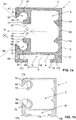
- FIG. 1a shows a cross-sectional shape of a preferred embodiment of an integrally formed by extrusion of metal side guide rail 1 for a roller shutter with a substantially rectangular guide chamber 5, which extends along a longitudinal direction L of the side guide rail 1.
- the side guide rails 1 has a substantially U-shaped cross-section, which has a substantially rectangular profiled rear wall 2, a perpendicularly extending from the rear wall 2, also substantially rectangular profiled first leg 3 and extending perpendicularly from the rear wall 2 and the first Leg 3 spaced apart mirror-like second leg 4 includes.
- first leg 3 is by means of a first conversion 7 with a first inner surface 57, a first receiving chamber 8 and at the free end of the second leg 4 by means of a second conversion 9 with a second inner surface 59, a second receiving chamber 10 for receiving a slide bar 12 provided.
- the receiving chambers each extend from a leg inner surface, ie a leg surface, which faces the guide chamber, against the guide chamber 5.
- the receiving chambers 8, 10, in particular end faces 37, 39 in this case form an opening 6 from the outside into the guide chamber 5, whereby a guide pin of a slat of the shutter - not shown in the figure - to guide in the longitudinal direction L from a main direction of introduction R in the guide chamber 5 is inserted.
- the clear width of the opening 6 is limited by said end faces 37, 39 in a direction perpendicular to the main direction of introduction H and to the longitudinal direction L.
- the first enclosure 7 provides a first opening 14 and the second enclosure 9 provides a second opening 16, the openings 14, 16 extending without interruption along the longitudinal direction L.
- the at least one first opening 14 is in a sectional plane perpendicular to the longitudinal direction L and through said openings 14, 16 through a first outer muzzle surface 67 and a first inner muzzle surface 77 and the second opening 16 through a second outer muzzle surface 69 and a second inner muzzle surface 79 limited.
- a first connecting line G1 extends through intersections of projections of the first outer mouth surface 67 with a first outer surface 47 of the first wall 7 and the first inner mouth surface 77 with a first end surface 37 of the first wall 7.
- a second connecting straight line G2 extends through intersections of projections of the second outer muzzle surface 69 with a second outer surface 49 of the second walling 9 and the second inner muzzle surface 79 with a second end surface 39 of the second walling 9.
- These two connecting straight lines G1, G2 close with the respective projection of the main direction of introduction R on said cutting plane in each case an angle ⁇ , ⁇ 'of well 45 degrees.
- the respective cut edges, which are in contact with the sliding strip 12, are dull, preferably rounded, so that no unnecessary damage occurs during intended use.
- the side guide rail 1 provides on a side facing away from the guide chamber 5 of the second leg 4 a formed by a molded Operaumwandung 17 T-groove 18 ready.
- This T-slot 18 extends along the longitudinal direction L and serves to receive a corresponding T-piece for the purpose of positive connection.
- the structures 19 extend continuously in Lenght L and are suitable for guiding a fastening element, for example a screw, to be introduced through the rear wall 2 towards a target area 20 between the structures 19.
- the target area 20 several holes are arranged in the longitudinal direction L, depending on the length of the lateral guide rail 1, for the passage of the Screw together. Adjacent holes are typically 0.3 meters apart. Screws to be inserted through these holes are guided by the structures 19 via a screw tip against the target area 20 and thus to the holes. When using screws, the screw head is usually against the main insertion direction R on the rear wall 2 from. The screw head projecting in this way is surrounded by the structures 19 and projects beyond it in the direction opposite to the main insertion direction R.
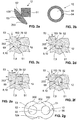
- FIG. 1b shows a further preferred embodiment of a side guide rail.
- the inner and outer mouth surfaces 67, 69, 77, 79 have a concave recess.
- the inner and / or outer muzzle surfaces can be excluded, so that the slide bar 12 can engage in the recess.
- the slide bar 12 is supported in particular laterally, ie transversely to its longitudinal direction better.
- the mouth surfaces 67, 69, 77, 79 may have an elevation 70 which advantageously slopes concavely to the sides transverse to the longitudinal direction and is defined in recesses 52a (see FIG. Fig. 2g ) engage and there with concave contact surfaces of the slide bar 12 in supportive contact.
- the recesses 52a may be formed as concave recesses, that is with rounded cross-sectional shape (to the longitudinal axis) without edge, the side guide rail 1 is then advantageously provided complementary.
- Fig. 1b Next is in Fig. 1b can be seen that the edges 17b in contrast to the rail 1 after Fig. 1a rounded and the end surfaces 17a are designed flattened. The former avoids exposed sharp edges and the latter helps to introduce the tensioner 21 into the T-slot 18.
- FIG. 2a, b are each a cross section of two different embodiments of a sliding strips 12 shown.
- FIGS. 2c-f are each a cross-section through various embodiments of the receiving chambers 8, 10, which are formed by the conversion 7, 9, shown with matching inventive embodiments of the slide bar 12.
- the cutting plane is perpendicular to the longitudinal direction of the slide bar 12, wherein the longitudinal direction of the slide bar 12 with inserted slide bar 12 corresponds to the longitudinal direction L.
- FIG. 2a shows a slide strip 12, which in a dimensionally stable manner an anchoring part 51, a transition part 52 and a guide part 53, the two wings 153, 253, provides.
- This slide bar 12 can be used with the side guide rail 1 described above.
- the slide bar 12, the anchoring part 51 and the guide member 53 at least in the uncompressed state does not fit through the opening 14 and 16 respectively, introduced from an open profile end of the side guide rail 1 in the receiving chamber 8 there open respectively 10 and inserted sliding.
- the anchoring part 51 of the slide strip 12, with correspondingly given elasticity can be pressed in under pressure from a direction perpendicular to the longitudinal direction L.
- the conversion 7 or 9 engages in a recess which extends between the guide member 53 and the anchoring part 51 due to the constricting transition part 52 along the longitudinal direction L, and thus fixes the slide bar 12 in the side guide rail 1 substantially in the corresponding Receiving chamber 8 and 10 against displacement perpendicular to the longitudinal direction L.
- Fig. 2b shows a further embodiment of a slide bar 12, which has a circular-view a round cross-section perpendicular to the longitudinal direction of the slide bar 12.
- the sliding strip in Essentially comprise a Gleitorn Sciences 54 with a recess 55 or a cavity 55.
- Said cavity is a continuous bore through the central axis of the slide bar 12 with a diameter of about 50% of the outer diameter of the slide bar 12. Such a bore is not mandatory. Matched to the respective material properties, a full sliding strip can definitely be used.
- This slide bar 12 is elastic, so that they can be pressed together pressed or pressed together through the opening 14 respectively 16 in the receiving chamber 8, wherein after pressing the inserted anchoring part 51 under at least partial omission of the external pressure in the corresponding receiving chamber 8 respectively 10 expands and the corresponding receiving chamber substantially fills.
- the corresponding conversion engages 7 respectively 9 in the elastic slide bar 12 and thus forms under pressure the transition part 52.
- the protruding through the respective opening 14 respectively 16 part of the slide bar 12 forms the guide member 53.
- the guide part 53 is formed such that two wings are formed similar to the wings 153, 253.
- Fig. 2c is a cross section of a preferred embodiment of the formed by the wall 7, 9 receiving chamber 8, 10 shown with correspondingly inserted slide bar 12.
- the receiving chamber 8, 10 has a substantially circular segment-shaped cross-section.
- a suitably eyeglass-shaped slide strip 12 is inserted in a form-fitting manner, wherein the slide strip 12 provides an anchoring part 51, a transition part 52 and a guide part 53.
- the guide part 53 comprises two projecting parts 153, 253, which here have the shape of a circular section.
- the protruding parts 153, 253 provide the corresponding sliding surfaces for sliding the guide pin (in the FIGS. 2c to 2f marked by unlabeled arrows).
- the receiving chamber 8, 10 is substantially filled by the anchoring part 51.
- the slide bar is thus formed at least partially complementary to the receiving chamber.
- the conversion 7, 9 engages in a recess which extends between the guide member 53 and the anchoring part 51 due to the constricting transition part 52 along the longitudinal direction L, and thus fixes the inserted slide bar 12.
- the mouth surface 69, 79 the Slide strip completely contact (see mouth 69 in Fig. 2c ) or only partially (see Mündungs behavior 79 in Fig. 2c ).
- both mouth surfaces can be completely or only partially in contact with the sliding strip 12.
- This slide bar 12 is rotated after removal from the receiving chamber 8, 10 by 180 degrees about a longitudinal axis of the slide bar 12 or an axis perpendicular to the said longitudinal axis in the same receiving chamber 8, 10 can be used and used as intended.
- Fig. 2g is another preferred embodiment of the slide bar 12, similar to that after Fig. 2c represented; also the slide bar 12 after Fig. 2g provides a circular anchoring part 51, a transition part 52, and a circular guide part 53. Next two parallel, circular and along the slide bar extending cavities or recesses 55 are provided. Also, this sliding strip, like those in Figs. 2b-f is so symmetrical that it can be rotated by 180 ° about the longitudinal axis of the slide bar 12 and used again.
- the side guide rail 1 advantageously engages in the recesses 52a and supports the slide bar 12 by surface contact from the side.
- the slide bar 12 on its outer surface elevations 300 (s. Fig. 2g ). The elevations can be as in Fig.
- the elevations 300 are advantageously shaped such that their outer contour is formed in cross-section in each case by a circle having a center point 302.
- This center 302 is preferably located on the formed by the cavity 55 inner surface of the slide bar 12 and a radius of this circle is then preferably smaller than a radius of the anchoring part 51 or the guide member 53 and larger than a smallest wall thickness of the slide bar 12 between the cavity 55 and Functionally, these elevations 300 are advantageous if the receiving chamber 8, 10 is too small in cross-section to accommodate the slide bar 12 and the latter must be reduced by material removal. It must then only the elevation 300 (partially) removed and not the whole outer surface of the slide bar 12 are processed.
- FIGS. 2d-f By way of example, further alternative embodiments of the receiving chambers 8, 10 and the respectively matching slide strips 12 are shown in cross-section.
- the symmetry of the embodiment of the slide bar 12 in the FIGS. 2d-f is deeper. It is the slide bar 12 only 180 degrees about a longitudinal axis of the slide bar 12th twisted in the same receiving chamber 8, 10 can be used and used as intended.
- the guide members 53 of the individual respectively fixed in the receiving chambers 8, 10 of the side guide rail 1 inserted and projecting through the corresponding openings 14, 16 from the receiving chambers different slide strips 12 narrow the clear width of the opening 6.
- the guide members 53 each protrude with one of their wings respectively protruding parts 153 via a first end face 37 of the conversion 7 respectively via a second end face 39 of the conversion 9 in the guide chamber 5.
- the two guide members 53 facing each other parallel sliding surfaces for sliding for the Guide bolt along the longitudinal direction L ready.
- the said guide parts 53 protrude in particular with their respective other wing or protruding part 253 via a first outer surface 47 of the wall 7 or via a second outer surface 49 of the wall 9 from the guide chamber 5.
- the guide members 53 also serve as a stop damper against abutment of the guide pin or a lamella from the main direction of insertion R.
- Said wings or protruding parts 153, 253 can rest on said surfaces 37, 39, 47, 49.
- Said wings 153, 253 are advantageously only in partial or no contact with said surfaces 37, 39, 47, 49, and are provided in such a way that said wings 153, 253 spring only under load on said surfaces 37, 39, 47, 49 come to large-scale edition, so counteracting such a large-scale edition cushioning or buffering the acting force.
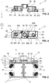
- FIG. 3 is a clamping element 21 for bracing lateral guide rails 1, which the above-mentioned features after Fig. 1 have shown in a side view.
- FIG. 4 shows a corresponding plan view of a clamping element 21.
- This clamping element 21 comprises a planar connecting element 30, from which in a main direction H, a first web 24 and a second web 28 extends, the webs 24, 28 parallel, spaced and perpendicular in a sectional plane to the longitudinal direction L have substantially the shape of a rectangle.
- a longer edge 242, 282 of this rectangle is in this case parallel to a longitudinal side 211 of the clamping element 21 and somewhat shorter than a width B of the opening of the T-slot 18, in which the clamping element 21 is intended to engage.
- the clamping element 21 comprises a at the free end of the first Bridge 24 subsequent flat, the first web 24 to the sides at least partially superior first engagement member 23 and adjoining the free end of the second web 28 flat, the second web 28 to the pages at least partially superior second engagement member 27.
- the first bridge 24 with the first engagement member 23, a first T-piece 22 and the second web 28 with the second engagement member 27, a second T-piece 26, wherein the T-pieces 22, 26 for engagement with the positive connection in respectively corresponding T-slots 18 a or two side guide rail (s) 1 are suitable.
- the clamping element 21 is integrally formed.
- the said engagement elements 23, 27 are rectangular in plan view with a long and a short side.
- the long side is in this case parallel to the longitudinal side 211 of the clamping element 21 and longer than the width B of the opening of the T-slot 18.
- the short side is substantially perpendicular to the long and is shorter than the width B of the opening of the T-slot 18th
- the clamping element 21 can be used with the longitudinal side 211 parallel to the longitudinal direction L through the opening of the T-slot in this (see. Left clamping element 21 in Fig. 6 ).
- the engagement elements 23, 27 are shaped such that once inserted by rotation they can reach under the partial wall 17 (cf. FIGS. 6 and 7 ).
- the clamping element 21 inserted in this way is rotatable about an axis parallel to the main direction H.
- the T-pieces 22, 26 engage under the Operaumwandung 17 in the T-groove 18 a.
- side surfaces 243 and 283 (see FIG Fig. 4 ) of the web 24 respectively 28 flush with the corresponding side surface of the corresponding engaging member 27, respectively. 23 are. This causes essentially a clockwise rotation of the tensioning element 21 to engage the T-pieces 22, 26, since the said flush surface provides a counterclockwise rotation, thereby not engaging the engagement elements 23, 27 with the sub-wall 17 can intervene.
- the assembly is harmonized and thus made more efficient.
- the removal of the clamping element 21 from the T-slot 18 is easy thanks to the stop, since you just need to turn back the twisted engaging clamping element 21 to the stop to pull it out of the T-slot 18 can.
- the Engagement elements 23, 27 Two in a top view (cf. Fig. 4 ) diametrically opposite corners of the engagement elements 23, 27 have recesses 231, 232, 271, 272 on.
- the Engagement elements 23, 27 are thus cut off at said corners at an angle.
- These recesses 231, 232, 271, 272 are preferably triangular and the corresponding sectional planes are preferably parallel to each other and parallel to the main direction H, the engagement elements 23, 27 are congruent in this plan view.
- the respective webs 24, 28 are also rectangular in plan view, wherein that part of the web 24 respectively 28, which in the plan view a said recess 231, 232, 271, 272 of the corresponding engagement element 23, 27 is also excluded.
- the webs 24, 48 are thus also cut at an angle at an angle, wherein the corresponding cutting planes preferably parallel to each other and parallel to the main direction H.
- a clamping element here a screw, in the recess 25, 29 can be used, so that the respective T-piece 22, 26 positionable in the corresponding T-slot 18 in locking clamping end position and by this screw in a depth 118 of T-groove 18 is clamped.
- the tensioning element 21 additionally provides, by means of the connecting element 30, a fastening means 32 which is provided in particular with a thread and for mounting the one side guide rail 1 clamped in a tensioning element 21 (cf. Fig. 6 ) or two by means of a clamping element 21 to a double-side guide rail braced individual side guide rails 1 (see. Fig. 7 ) with the aid of a conventional console.
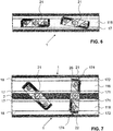
- FIG. 5 shows schematically how the tensioning element 21 is inserted from direction A, which is substantially perpendicular to the longitudinal direction L of the side guide rails 1, into two side guide rails 1 to be connected to a double-sided guide rail.
- direction A which is substantially perpendicular to the longitudinal direction L of the side guide rails 1
- the two side guide rails 1 are positioned such that touch their rear walls 2 and the T-grooves 18 are integrally formed on the same side.
- the recesses 231, 232, 271, 272 see Fig.
- the T-slots 18 are hereby preferably somewhat asymmetrically shaped, so that the recess 171 of the T-slot 18 (see Fig. 1 ) is deeper than a recess 172 of the T-slot 18.
- the engagement elements 23, 27 are in the direction parallel to the L Lucasshold 211 of the clamping element 21 on both sides a little further (about 0.5mm) on the webs 24, 28 from when the recess 172 of T-groove 18 is deep.
- the engagement elements 23, 27 during rotation of the clamping element 21 to engage in the depth of the recess 172 of the T-groove 18, which blocks further rotation, while in the depth of the recess 171 of the T-slot 18, a cavity 174 (FIG.
- Fig. 5 arises. It is of course important to ensure that the side surfaces of the webs 24, 28 do not already hit the Generalumwandung 17. Therefore, as already mentioned above, the longer edge 242, 282 is advantageously somewhat shorter than the width B of the opening of the T-groove 18. This has the advantage that pressed by turning the clamping element 21 used to the abovementioned stop, the rear walls 2 of the two side guide rails 1 become.
- the two T-pieces 22, 26 of the clamping element 21 are in this case arranged on the correspondingly large connecting element 30 spaced apart, that the two side guide rails 1 in the final tensioned state with its rear walls 2 in close contact and that the respective main directions of introduction R and R 'in Are essentially parallel.
- the rich contact of the said rear walls 2 is ensured in particular by a somewhat asymmetrically designed Operaumwandung 17.
- a console element from the main direction H engage in the fastening means 32.
- An alternative embodiment of the clamping element 21 may be designed mirror-like, so that a corresponding rotation of the clamping element 21 after its insertion is possible only in the counterclockwise direction.
- FIG. 6 illustrates two clamping elements 21 inserted into a single lateral guide rail 1. Both clamping elements 21 are set through the opening of the partial wall 17 to the depth 118 of the T-slot 18, wherein the right clamping element 21 is additionally twisted and engages under the partial wall 17.
- FIG. 7 shows two clamping element 21, which are each used to the depth 118 of the respective T-slot 18 in two on the rear walls 2 touching side guide rails 1.
- the right clamping element 21 is additionally rotated clockwise by about 45 degrees, so that the clamping element engages under the respective Operaumwandept 17.
- a cavity 174 is formed in the respectively deeper recess 171, while the corresponding T-pieces 22, 26 in the depth of the recess 172 are pressed together by corresponding rotation of the contacting rear walls 2 of the two side guide rails 1.
- the lateral guide rail according to the invention has the advantage that it offers in particular an optimized sliding system for a guide bolt by sliding strips, preferably also a doppelrundschnurförmig, preferably spectacle-shaped profiled strand is used as a sliding strip, such that the embracing part covered by the receiving chamber is jammed in the receiving chamber and the projecting over the receiving chamber guide part of the slide bar outside said sliding system and said stop damper provides. Furthermore, a clamping element is provided which makes it possible in a simple way to make a double-sided guide rail from the single-side guide rail according to the invention.
Landscapes
- Engineering & Computer Science (AREA)
- Structural Engineering (AREA)
- Architecture (AREA)
- Civil Engineering (AREA)
- Operating, Guiding And Securing Of Roll- Type Closing Members (AREA)
Applications Claiming Priority (1)
| Application Number | Priority Date | Filing Date | Title |
|---|---|---|---|
| CH3192011 | 2011-02-23 |
Publications (1)
| Publication Number | Publication Date |
|---|---|
| EP2492434A1 true EP2492434A1 (fr) | 2012-08-29 |
Family
ID=45656292
Family Applications (1)
| Application Number | Title | Priority Date | Filing Date |
|---|---|---|---|
| EP20120156346 Withdrawn EP2492434A1 (fr) | 2011-02-23 | 2012-02-21 | Rail de guidage latéral doté d'un barre de glissement |
Country Status (1)
| Country | Link |
|---|---|
| EP (1) | EP2492434A1 (fr) |
Citations (8)
| Publication number | Priority date | Publication date | Assignee | Title |
|---|---|---|---|---|
| CH406597A (de) * | 1963-12-05 | 1966-01-31 | W Baumann Fa | Seitenführung für Rolladen |
| DE7731330U1 (de) | 1977-10-11 | 1978-02-02 | Gerhardi & Cie, 5880 Luedenscheid | Rolladen mit einem rolladenpanzer und mit u-leichtmetallfuehrungsschienen |
| DE8236408U1 (de) | 1982-12-24 | 1983-04-14 | Gerhardi & Cie, 5880 Lüdenscheid | Fuehrungsschiene fuer rollaeden |
| DE3141132A1 (de) * | 1981-10-16 | 1983-05-11 | Helmut 7152 Aspach Lehr | "fuehrungsschiene fuer rollaeden o.dgl." |
| DE3401096A1 (de) | 1984-01-13 | 1985-08-01 | Hörmann KG Bielefeld, 4800 Bielefeld | Fuehrungsschienenprofil fuer rolltorblaetter |
| CH664599A5 (en) * | 1984-06-14 | 1988-03-15 | Novoplast Gmbh | Guide channels for slats of roller blinds or shutters - are formed from rigid PVC with pads of flexible PVC for noise reduction |
| DE19823853A1 (de) | 1998-05-28 | 1998-11-05 | Werner Dipl Ing Dietzsch | Seitenführungsschienen |
| WO2004042248A2 (fr) | 2002-10-31 | 2004-05-21 | Tsuchiya Tsco Co., Ltd. | Element amortisseur et procede de fabrication de celui-ci |
-
2012
- 2012-02-21 EP EP20120156346 patent/EP2492434A1/fr not_active Withdrawn
Patent Citations (8)
| Publication number | Priority date | Publication date | Assignee | Title |
|---|---|---|---|---|
| CH406597A (de) * | 1963-12-05 | 1966-01-31 | W Baumann Fa | Seitenführung für Rolladen |
| DE7731330U1 (de) | 1977-10-11 | 1978-02-02 | Gerhardi & Cie, 5880 Luedenscheid | Rolladen mit einem rolladenpanzer und mit u-leichtmetallfuehrungsschienen |
| DE3141132A1 (de) * | 1981-10-16 | 1983-05-11 | Helmut 7152 Aspach Lehr | "fuehrungsschiene fuer rollaeden o.dgl." |
| DE8236408U1 (de) | 1982-12-24 | 1983-04-14 | Gerhardi & Cie, 5880 Lüdenscheid | Fuehrungsschiene fuer rollaeden |
| DE3401096A1 (de) | 1984-01-13 | 1985-08-01 | Hörmann KG Bielefeld, 4800 Bielefeld | Fuehrungsschienenprofil fuer rolltorblaetter |
| CH664599A5 (en) * | 1984-06-14 | 1988-03-15 | Novoplast Gmbh | Guide channels for slats of roller blinds or shutters - are formed from rigid PVC with pads of flexible PVC for noise reduction |
| DE19823853A1 (de) | 1998-05-28 | 1998-11-05 | Werner Dipl Ing Dietzsch | Seitenführungsschienen |
| WO2004042248A2 (fr) | 2002-10-31 | 2004-05-21 | Tsuchiya Tsco Co., Ltd. | Element amortisseur et procede de fabrication de celui-ci |
Similar Documents
| Publication | Publication Date | Title |
|---|---|---|
| EP2009293B1 (fr) | Dispositif destiné à lier un rail de profilé avec un autre composant | |
| EP1135616B1 (fr) | Assemblage en t de deux barreaux profiles | |
| EP2443352B1 (fr) | Système de liaison de barres profilées | |
| EP1956250A2 (fr) | Profilé de type rail | |
| EP2029946A2 (fr) | Système de montage, en particulier pour modules solaires | |
| DE102015108275A1 (de) | Eckblende für Hohlprofil-Eckverbinder, Eckverbinder, Eckverbinder-Bausatz, Rahmenstruktur und Schutzgitter | |
| AT510740B1 (de) | Anschraubtasche für die aufnahme von bandzapfen eines türbandes | |
| EP0967341A2 (fr) | Connection montant et entretoise | |
| DE102008036386A1 (de) | Rohrschelle und Profilelement für eine Rohrschelle | |
| DE102005060817B4 (de) | Nutenstein, Ankerstein, Profilverbindersystem und Profilverbund | |
| EP2492434A1 (fr) | Rail de guidage latéral doté d'un barre de glissement | |
| DE202015100200U1 (de) | Bandlappenanordnung eines Bandes | |
| EP1548200B1 (fr) | Façade avec montants et traverses | |
| EP0348853A2 (fr) | Tendeur | |
| EP2243887A2 (fr) | Elément de ferrure | |
| DE202007007976U1 (de) | Montagesystem insbesondere Solarmodule | |
| EP1524377A1 (fr) | Façade | |
| DE102015122791A1 (de) | Profilschiene mit Griffelement | |
| EP1602836A1 (fr) | Nervure raidisseuse pour bois massif | |
| DE202007015154U1 (de) | System zur Befestigung eines Beschlagteils an einem Hohlprofil | |
| EP1830029A2 (fr) | Ensemble de lamelles pour façades | |
| DE102015112019B3 (de) | Anordnung eines Scharniers an einem Hohlkammerprofil | |
| BE1031648B1 (de) | Befestigungselement für eine Fassadenplatte und Anordnung mit einer Fassadenplatte und dem Befestigungselement | |
| EP0965714A1 (fr) | Fixation d'une ferrure | |
| EP1199481A1 (fr) | Liaison transversale pour des barres profilées |
Legal Events
| Date | Code | Title | Description |
|---|---|---|---|
| PUAI | Public reference made under article 153(3) epc to a published international application that has entered the european phase |
Free format text: ORIGINAL CODE: 0009012 |
|
| AK | Designated contracting states |
Kind code of ref document: A1 Designated state(s): AL AT BE BG CH CY CZ DE DK EE ES FI FR GB GR HR HU IE IS IT LI LT LU LV MC MK MT NL NO PL PT RO RS SE SI SK SM TR |
|
| AX | Request for extension of the european patent |
Extension state: BA ME |
|
| 17P | Request for examination filed |
Effective date: 20130207 |
|
| 17Q | First examination report despatched |
Effective date: 20150319 |
|
| 19U | Interruption of proceedings before grant |
Effective date: 20150904 |
|
| 19W | Proceedings resumed before grant after interruption of proceedings |
Effective date: 20181001 |
|
| STAA | Information on the status of an ep patent application or granted ep patent |
Free format text: STATUS: THE APPLICATION HAS BEEN WITHDRAWN |
|
| 18W | Application withdrawn |
Effective date: 20181001 |