EP2492431B1 - Device for attaching slats forming a shutter - Google Patents
Device for attaching slats forming a shutter Download PDFInfo
- Publication number
- EP2492431B1 EP2492431B1 EP12001087.1A EP12001087A EP2492431B1 EP 2492431 B1 EP2492431 B1 EP 2492431B1 EP 12001087 A EP12001087 A EP 12001087A EP 2492431 B1 EP2492431 B1 EP 2492431B1
- Authority
- EP
- European Patent Office
- Prior art keywords
- profile
- profiles
- fact
- additional
- assemblies
- Prior art date
- Legal status (The legal status is an assumption and is not a legal conclusion. Google has not performed a legal analysis and makes no representation as to the accuracy of the status listed.)
- Not-in-force
Links
- 238000000429 assembly Methods 0.000 claims description 8
- 239000000463 material Substances 0.000 claims description 6
- XAGFODPZIPBFFR-UHFFFAOYSA-N aluminium Chemical compound [Al] XAGFODPZIPBFFR-UHFFFAOYSA-N 0.000 claims description 4
- 229910052782 aluminium Inorganic materials 0.000 claims description 4
- 239000011810 insulating material Substances 0.000 claims description 3
- 239000004952 Polyamide Substances 0.000 claims description 2
- 239000000956 alloy Substances 0.000 claims description 2
- 229910045601 alloy Inorganic materials 0.000 claims description 2
- 229920002647 polyamide Polymers 0.000 claims description 2
- 239000004411 aluminium Substances 0.000 claims 1
- 238000009413 insulation Methods 0.000 description 4
- 238000012423 maintenance Methods 0.000 description 3
- 230000014759 maintenance of location Effects 0.000 description 2
- 239000004033 plastic Substances 0.000 description 2
- 230000002787 reinforcement Effects 0.000 description 2
- 230000006978 adaptation Effects 0.000 description 1
- 230000000712 assembly Effects 0.000 description 1
- 238000013461 design Methods 0.000 description 1
- 230000001627 detrimental effect Effects 0.000 description 1
- 238000006073 displacement reaction Methods 0.000 description 1
- 230000000694 effects Effects 0.000 description 1
- 238000003780 insertion Methods 0.000 description 1
- 230000037431 insertion Effects 0.000 description 1
- 238000012986 modification Methods 0.000 description 1
- 230000004048 modification Effects 0.000 description 1
- 238000011160 research Methods 0.000 description 1
- 125000006850 spacer group Chemical group 0.000 description 1
Images


Classifications
-
- E—FIXED CONSTRUCTIONS
- E06—DOORS, WINDOWS, SHUTTERS, OR ROLLER BLINDS IN GENERAL; LADDERS
- E06B—FIXED OR MOVABLE CLOSURES FOR OPENINGS IN BUILDINGS, VEHICLES, FENCES OR LIKE ENCLOSURES IN GENERAL, e.g. DOORS, WINDOWS, BLINDS, GATES
- E06B9/00—Screening or protective devices for wall or similar openings, with or without operating or securing mechanisms; Closures of similar construction
- E06B9/02—Shutters, movable grilles, or other safety closing devices, e.g. against burglary
- E06B9/04—Shutters, movable grilles, or other safety closing devices, e.g. against burglary of wing type, e.g. revolving or sliding
-
- E—FIXED CONSTRUCTIONS
- E06—DOORS, WINDOWS, SHUTTERS, OR ROLLER BLINDS IN GENERAL; LADDERS
- E06B—FIXED OR MOVABLE CLOSURES FOR OPENINGS IN BUILDINGS, VEHICLES, FENCES OR LIKE ENCLOSURES IN GENERAL, e.g. DOORS, WINDOWS, BLINDS, GATES
- E06B3/00—Window sashes, door leaves, or like elements for closing wall or like openings; Layout of fixed or moving closures, e.g. windows in wall or like openings; Features of rigidly-mounted outer frames relating to the mounting of wing frames
- E06B3/70—Door leaves
- E06B3/7003—Door leaves consisting of several adjacent similar elements, e.g. planks, without outer covering panels
Definitions
- the present invention relates to the field of shutter flaps and in particular to adaptations to optimize the fixing between the blades of said leaves and the proposed thermal insulation.
- the shutter flaps are conventionally formed of blades arranged and fixed together in the same plane, the fastening being completed on one of the sides of the flap by an upper bar and a lower reinforcement bar between which is disposed diagonally an additional bar said scarf.
- the blades constituting a leaf have been proposed in the document EP 2050916A in the form of hollow profiled subassemblies comprising an outer profile and an inner profile whose inner faces disposed vis-a-vis are connected by flat profiles arranged perpendicularly and in a different material from the blades to ensure the breaking of the bridge thermal between the outer part and the inner part of the wing and therefore the flap.
- the positioning and fixing of the blades together, that is to say said profiled subsets is implemented by the edges of said outer and inner profiles which are preformed concave and convex shapes that cooperate to allow sliding longitudinal blades between them and maintaining them in at least transverse position.
- the holding in position is completed by said bars.
- This assembly is likely to be improved.
- a fixing device comprising the hollow profiled subassemblies forming the blades of a shutter and including an outer profile and an inner profile whose inner faces arranged opposite are connected and braced by flat sections arranged perpendicularly and in a material different from that of the boards, the longitudinal edges of said outer and inner profiles being preformed concave and convex shapes that cooperate to achieve the maintenance in transverse position of the blades between them.
- This device is remarkable in that it further comprises an additional fastening profile which, coming to be positioned between the internal faces disposed opposite said subsets of hollow profiles and straddling between two subassemblies, is preformed male or female forms cooperating with corresponding female or male shapes preformed in said inner faces disposed opposite said hollow profile subassemblies for transverse retention of said blades together, said additional section adopts an H profile between the branches of which are positioned longitudinal bearing surfaces formed on either side of their connecting surfaces in the longitudinal edges of the profiles forming the hollow profiled subassemblies.
- This profile advantageously completes the fixing between the blades forming the shutter. Indeed, this profile completes and guarantee transverse retention that could not be without said bars because the blades had a necessary game to their assembly, game likely to make the assembly less accurate and the assembly obtained less rigid.
- the profile thus has particularly simple shapes to which will correspond the corresponding forms of home in the inner faces of the inner and outer profiles forming the blades.
- said additional fastening profile is made of a material different from that of the blades and more precisely in an insulating material. This feature prevents this additional connecting section does a thermal bridge. Thus, the fastening profile does not counteract the rupture of the thermal bridge made by the flat sections and the volume present between said inner and outer sections forming the hollow subsets constituting the blades.
- said additional fastening profile is hollow.
- the presence of a volume of air optimizes the thermal break and the insulation.
- said additional fastening profile adopts the shape of a hollow parallelepiped whose two faces facing each other are preformed with parallel ribs cooperating with corresponding preformed grooves in said internal faces arranged in screws. with respect to said hollow profiled subsets.
- the end of the ribs is bevelled to form an inclination facilitating the positioning of said additional profile in the longitudinal direction and the self-positioning of the blades together.
- said additional profile and the shutter blades are dimensioned so that the mounting of said profile is made to the mallet.
- An assembly with a mallet defines that the adjustment proposed by the device the invention will not only optimize the maintenance in transverse position of the blades together but also the maintenance in the longitudinal position.
- grooves are formed in said inner faces for retaining the longitudinal edges of the flat profiles connecting and bracing, the grooves formed in the inner faces of the profiles forming the hollow profiled subassemblies
- the inner flange of the outer flange of the grooves formed in said inner faces is used to retain the longitudinal flanges of the flat connecting and bracing profiles.
- the shutter blades are made of aluminum or equivalent alloy.
- This feature defines an application where the invention is particularly useful. Indeed, while hollow plastic blades (eg PVC) have elasticity contributing to maintaining position without reducing the ease of positioning of the blades together, aluminum blades do not have this elasticity. Also, the game necessary for their mounting does not allow a positional holding which can then be achieved by the additional section of the invention.
- the additional fastening profile is made of polyamide.
- a plastic material facilitates the realization and implementation especially when said blades are made of aluminum.
- this is an insulating material
- the invention also relates to the component adopting all or part of the characteristics described above.
- the shutter flap referenced B as a whole is conventionally formed of a plurality of vertical blades (three of which L1, L2 and L3 are shown) arranged and fixed together in the same plane.
- Fixing is here completed on the inner face of the leaf B by an upper bar 100 and a lower reinforcement bar (not shown) between which is disposed diagonally an additional bar said scarf 200.
- Said blades L1, L2, L3 are formed of hollow profiled subassemblies 300 comprising a profile outside 310 and an inner profile 320 whose inner faces 311 and 321 arranged vis-à-vis are connected and braced by flat profiles or bars 400 (here two flat profiles for each blade) which, arranged perpendicularly, are of different material of the profiles for insulation purposes.
- the longitudinal flanges of said outer and inner profiles 310 and 320 are preformed with concave and convex shapes that cooperate from one blade L1 to the other L2 in a sliding fit to effect longitudinal positioning and transverse positioning of the blades between they due to the constant spacing of the sections forming the blades.
- This constant spacing and the rigidity of the hollow profiled subassemblies formed by the blades is implemented by said bars 400 which connect and brace said outer 310 and inner 320 profiles.
- Grooves 312 and 322 are preformed in the internal faces 311 and 321 of said outer 310 and inner 320 profiles to accommodate and retain the longitudinal edges of said bars 400 which are arranged perpendicularly to the plane formed by the blades L.
- the edges of the latter are framed by profiles 500 adopting a U-shaped profile.
- an additional fastening section 600 which is positioned between the inner faces 311 and 321 arranged opposite said subsets of hollow sections 300 forming the blades L and straddling between two subsets that is to say between two blades here L1 and L2 at their longitudinal connecting surfaces.
- the additional fixing profile 600 does not interfere in said connection but completes it by cooperating with surfaces disposed on either side of said surfaces. longitudinal links.
- This additional profile 600 adopts the shape of an H where the central bar is hollow or the symmetrical shape of a hollow parallelepiped having an extension of two of its sides, longitudinal ribs 610 and 620 constituting projections or male shapes that will cooperate with grooves 313 and 323 forming the corresponding female shapes preformed in said inner faces 311 and 321.
- Said ribs 610 and 620 and said grooves 313 and 323 adopt corresponding polygonal profiles forming bearing surfaces opposing the transverse displacement of the blades together.
- the end of the ribs 610 and 620 oriented forward in the direction of insertion of the additional profiles 600 is beveled to form an inclination facilitating the positioning of said additional profile in the longitudinal direction and the self-positioning of the blades between they especially in the transverse direction.
- the inclined plane 611 and 621 formed in the front end of the ribs 610 and 620 joins a surface 612 and 622 of the rear portion of the rib, perpendicular to the plane surface formed by the blades (or parallel to the flat profiles d spacer).
- These surfaces 612 and 622 abut against a corresponding rectilinear surface of the reception grooves 313 and 323 of said ribs 610 and 620.
- Said surfaces 612 and 622 are arranged opposite one another on the profile additional fastening 600 and cooperate with different blade sections on both sides of the connection zone of said blades. The spacing of said surfaces 612 and 622 is defined so that the mounting of said additional fastening section 600 is made to the mallet.
- the receiving grooves 313 and 323 of said ribs are preformed in the inner faces 311 and 321 of the profiles forming the blades between the longitudinal outer edges preformed for connection between blades and the longitudinal grooves 312 and 322 preformed to accommodate and retain the longitudinal edges of the bars 400.
- said grooves 313 and 323 formed in the inner faces 311 and 321 of the profiles 310 and 320 forming the hollow profiled subassemblies 300 for retaining the ribs of the additional fastening profile 600 adopt as the inner rim, the outer edge. grooves in said inner faces for retaining the longitudinal edges of the connecting bars and bracing.
- an additional fastener profile is positioned at each end (high and low) of blades.
Landscapes
- Engineering & Computer Science (AREA)
- Structural Engineering (AREA)
- Architecture (AREA)
- Civil Engineering (AREA)
- Wing Frames And Configurations (AREA)
- Operating, Guiding And Securing Of Roll- Type Closing Members (AREA)
- Connection Of Plates (AREA)
Description
La présente invention a trait au domaine des battants de volet et notamment aux adaptations permettant d'optimiser la fixation entre les lames desdits battants ainsi que l'isolation thermique proposée.The present invention relates to the field of shutter flaps and in particular to adaptations to optimize the fixing between the blades of said leaves and the proposed thermal insulation.
Les battants de volet sont classiquement formés de lames disposées et fixées entre elles selon un même plan, la fixation étant complétée sur une des faces du battant par une barre supérieure et par une barre inférieure de renfort entre lesquelles vient se disposer en diagonale une barre supplémentaire dite écharpe.The shutter flaps are conventionally formed of blades arranged and fixed together in the same plane, the fastening being completed on one of the sides of the flap by an upper bar and a lower reinforcement bar between which is disposed diagonally an additional bar said scarf.
Plus récemment, les lames constituant un battant ont été proposées dans le document
La mise en position et la fixation des lames entre elles, c'est-à-dire desdits sous-ensembles profilés est mise en oeuvre par les rebords desdits profilés extérieur et intérieur qui sont préformés de formes concaves et convexes qui coopèrent pour autoriser le glissement longitudinal des lames entre elles et leur maintien en position au moins transversal. Le maintien en position est complété par lesdites barres.The positioning and fixing of the blades together, that is to say said profiled subsets is implemented by the edges of said outer and inner profiles which are preformed concave and convex shapes that cooperate to allow sliding longitudinal blades between them and maintaining them in at least transverse position. The holding in position is completed by said bars.
Cet assemblage est susceptible d'être amélioré.This assembly is likely to be improved.
Partant de cet état de fait, la demanderesse a imaginé d'optimiser la fixation entre eux desdits sous ensembles profilés creux formant les lames de volet sans créer de pont thermique préjudiciable à l'isolation apportée par une telle solution de volet.On the basis of this state of affairs, the plaintiff has imagined to optimize the fixing between them of the aforementioned hollow profile assemblies forming the shutter blades without creating a thermal bridge detrimental to the insulation provided by such a shutter solution.
Ses recherches ont abouti à la conception d'un dispositif de fixation comprenant les sous-ensembles profilés creux formant les lames d'un volet et incluant un profilé extérieur et un profilé intérieur dont les faces internes disposées en vis-à-vis sont reliées et entretoisées par des profilés plats disposés perpendiculairement et en matériau différent de celui des lames,
les rebords longitudinaux desdits profilés extérieur et intérieur étant préformés de formes concaves et convexes qui coopèrent pour réaliser le maintien en position transversal des lames entre elles.His research led to the design of a fixing device comprising the hollow profiled subassemblies forming the blades of a shutter and including an outer profile and an inner profile whose inner faces arranged opposite are connected and braced by flat sections arranged perpendicularly and in a material different from that of the boards,
the longitudinal edges of said outer and inner profiles being preformed concave and convex shapes that cooperate to achieve the maintenance in transverse position of the blades between them.
Ce dispositif est remarquable en ce qu'il comprend en outre un profilé supplémentaire de fixation qui, venant se positionner entre les faces internes disposées en vis-à-vis desdits sous-ensembles de profilés creux et à cheval entre deux sous-ensembles, est préformé de formes mâles ou femelles coopérant avec des formes correspondantes femelles ou mâles préformées dans lesdites faces internes disposées en vis-à-vis desdits sous ensembles profilés creux à des fins de retenue transversale desdites lames entre elles,
ledit profilé supplémentaire adopte un profil en H entre les branches duquel viennent se positionner des surfaces d'appui longitudinales ménagées de part et d'autre de leurs surfaces de liaison dans les rebords longitudinaux des profilés formant les sous ensembles profilés creux.This device is remarkable in that it further comprises an additional fastening profile which, coming to be positioned between the internal faces disposed opposite said subsets of hollow profiles and straddling between two subassemblies, is preformed male or female forms cooperating with corresponding female or male shapes preformed in said inner faces disposed opposite said hollow profile subassemblies for transverse retention of said blades together,
said additional section adopts an H profile between the branches of which are positioned longitudinal bearing surfaces formed on either side of their connecting surfaces in the longitudinal edges of the profiles forming the hollow profiled subassemblies.
Ce profilé vient compléter avantageusement la fixation entre les lames formant le volet. En effet, ce profilé vient compléter et garantir la retenue transversale qui ne pouvait l'être sans lesdites barres du fait que les lames présentaient un jeu nécessaire à leur montage, jeu susceptible de rendre le montage moins précis et l'assemblage obtenu moins rigide. En outre, le profilé présente ainsi des formes particulièrement simples auxquelles vont correspondre les formes d'accueil correspondantes dans les faces internes des profilés intérieurs et extérieurs formant les lames.This profile advantageously completes the fixing between the blades forming the shutter. Indeed, this profile completes and guarantee transverse retention that could not be without said bars because the blades had a necessary game to their assembly, game likely to make the assembly less accurate and the assembly obtained less rigid. In addition, the profile thus has particularly simple shapes to which will correspond the corresponding forms of home in the inner faces of the inner and outer profiles forming the blades.
Selon une autre caractéristique particulièrement avantageuse, ledit profilé supplémentaire de fixation est réalisé dans un matériau différent de celui des lames et plus exactement dans un matériau isolant. Cette caractéristique évite que ce profilé supplémentaire de liaison ne réalise un pont thermique. Ainsi, le profilé de fixation ne contrecarre pas la rupture du pont thermique réalisé par les profilés plats et par le volume présent entre lesdits profilés intérieurs et extérieurs formant les sous ensembles creux constituant les lames.According to another particularly advantageous feature, said additional fastening profile is made of a material different from that of the blades and more precisely in an insulating material. This feature prevents this additional connecting section does a thermal bridge. Thus, the fastening profile does not counteract the rupture of the thermal bridge made by the flat sections and the volume present between said inner and outer sections forming the hollow subsets constituting the blades.
Selon une autre caractéristique particulièrement avantageuse, ledit profilé supplémentaire de fixation est creux. La présence d'un volume d'air optimise la rupture du pont thermique et l'isolation.According to another particularly advantageous feature, said additional fastening profile is hollow. The presence of a volume of air optimizes the thermal break and the insulation.
Ainsi, selon une autre caractéristique particulièrement avantageuse, ledit profilé supplémentaire de fixation adopte la forme d'un parallélépipède creux dont deux faces en vis-à-vis sont préformées de nervures parallèles venant coopérer avec des gorges correspondantes préformées dans lesdites faces internes disposées en vis-à-vis desdits sous ensembles profilés creux.Thus, according to another particularly advantageous characteristic, said additional fastening profile adopts the shape of a hollow parallelepiped whose two faces facing each other are preformed with parallel ribs cooperating with corresponding preformed grooves in said internal faces arranged in screws. with respect to said hollow profiled subsets.
Selon une autre caractéristique particulièrement avantageuse, l'extrémité des nervures est biseautée pour former une inclinaison facilitant la mise en position dudit profilé supplémentaire dans le sens longitudinal et l'auto-positionnement des lames entre elles.According to another particularly advantageous feature, the end of the ribs is bevelled to form an inclination facilitating the positioning of said additional profile in the longitudinal direction and the self-positioning of the blades together.
Selon une autre caractéristique particulièrement avantageuse, ledit profilé supplémentaire et les lames du volets sont dimensionnés de sorte que le montage dudit profilé soit réalisé au maillet. Un montage au maillet définit que l'ajustement proposé par le dispositif de l'invention va non seulement optimiser le maintien en position transversal des lames entre elles mais également le maintien en position longitudinale.According to another particularly advantageous feature, said additional profile and the shutter blades are dimensioned so that the mounting of said profile is made to the mallet. An assembly with a mallet defines that the adjustment proposed by the device the invention will not only optimize the maintenance in transverse position of the blades together but also the maintenance in the longitudinal position.
Selon une autre caractéristique particulièrement avantageuse, où des gorges sont pratiquées dans lesdites faces internes à des fins de retenue des rebords longitudinaux des profilés plats de liaison et d'entretoisement, les gorges pratiquées dans les faces internes des profilés formant les sous-ensembles profilés creux à des fins de retenue des nervures du profilé supplémentaire de fixation adoptent comme rebord intérieur, le rebord extérieur des gorges pratiquées dans lesdites faces internes à des fins de retenue des rebords longitudinaux des profilés plats de liaison et d'entretoisement. Ainsi, la gorge supplémentaire, nécessaire sur chaque rebord de la face interne de chaque profilé formant le sous-ensemble creux constituant les lames, profite des préformes déjà présentes dans la face interne.According to another particularly advantageous feature, grooves are formed in said inner faces for retaining the longitudinal edges of the flat profiles connecting and bracing, the grooves formed in the inner faces of the profiles forming the hollow profiled subassemblies In order to retain the ribs of the additional fastening profile, the inner flange of the outer flange of the grooves formed in said inner faces is used to retain the longitudinal flanges of the flat connecting and bracing profiles. Thus, the additional groove, required on each edge of the inner face of each section forming the hollow subassembly constituting the blades, takes advantage of preforms already present in the inner face.
Selon une autre caractéristique particulièrement avantageuse, les lames du volet sont en aluminium ou alliage équivalent. Cette caractéristique définit une application où l'invention est particulièrement utile. En effet, alors que des lames creuses plastiques (par exemple en PVC) présentent une élasticité contribuant au maintien en position sans diminuer la facilité de mise en position des lames entre elles, des lames en aluminium ne présentent pas cette élasticité. Aussi, le jeu nécessaire à leur montage ne permet pas un maintien en position qui ne peut alors être réalisé que par le profilé supplémentaire de l'invention.According to another particularly advantageous feature, the shutter blades are made of aluminum or equivalent alloy. This feature defines an application where the invention is particularly useful. Indeed, while hollow plastic blades (eg PVC) have elasticity contributing to maintaining position without reducing the ease of positioning of the blades together, aluminum blades do not have this elasticity. Also, the game necessary for their mounting does not allow a positional holding which can then be achieved by the additional section of the invention.
Selon une autre caractéristique particulièrement avantageuse, le profilé supplémentaire de fixation est réalisé en polyamide. L'utilisation d'une matière plastique facilite la réalisation et la mise en place notamment lorsque lesdites lames sont réalisées en aluminium. De plus, il s'agit dans ce cas là d'un matériau isolantAccording to another particularly advantageous characteristic, the additional fastening profile is made of polyamide. The use of a plastic material facilitates the realization and implementation especially when said blades are made of aluminum. In addition, this is an insulating material
Bien entendu, l'invention concerne également le volet adoptant tout ou partie des caractéristiques ci-dessus décrites.Of course, the invention also relates to the component adopting all or part of the characteristics described above.
Les concepts fondamentaux de l'invention venant d'être exposés ci-dessus dans leur forme la plus élémentaire, d'autres détails et caractéristiques ressortiront plus clairement à la lecture de la description qui suit et en regard des dessins annexés, donnant à titre d'exemple non limitatif, un mode de réalisation d'un dispositif de fixation conforme à l'invention.The basic concepts of the invention having been described above in their most elementary form, other details and characteristics will emerge more clearly on reading the description which follows and with reference to the appended drawings, giving non-limiting example, an embodiment of a fastening device according to the invention.
-
La
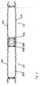
figure 1 est une vue en perpective éclatée d'une portion d'un mode de réalisation de battant de volet conforme à l'invention;Thefigure 1 is an exploded perspective view of a portion of an embodiment of shutter flap according to the invention; -
La
figure 2 est une vue en perspective éclatée de détail d'une fixation entre deux lames;Thefigure 2 is an exploded perspective view of detail of an attachment between two blades; -
La
figure 3 est une vue de dessus de la liaison obtenue entre deux lames;Thefigure 3 is a top view of the connection obtained between two blades; -
La
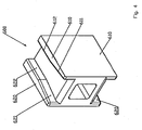
figure 4 est une vue en perspective du profilé de fixation seul.Thefigure 4 is a perspective view of the mounting profile alone.
Tel qu'illustré sur le dessin de la
La fixation est ici complétée sur la face intérieure du battant B par une barre supérieure 100 et par une barre inférieure de renfort (non représentée) entre lesquelles vient se disposer en diagonale une barre supplémentaire dite écharpe 200.Fixing is here completed on the inner face of the leaf B by an
Lesdites lames L1, L2, L3 sont formées de sous-ensembles profilés creux 300 comprenant un profilé extérieur 310 et un profilé intérieur 320 dont les faces internes 311 et 321 disposées en vis-à-vis sont reliées et entretoisées par des profilés plats ou barrettes 400 (ici deux profilés plats pour chaque lame) qui, disposés perpendiculairement, sont en matériau différent de celui des profilés à des fins d'isolation.Said blades L1, L2, L3 are formed of hollow profiled
Comme illustrés sur le dessin des
Cet écartement constant et la rigidité des sous ensembles profilés creux formés par les lames est mis en oeuvre par lesdites barrettes 400 qui lient et entretoisent lesdits profilés extérieur 310 et intérieur 320. Des gorges 312 et 322 sont préformées dans les faces internes 311 et 321 desdits profilés extérieur 310 et intérieur 320 pour accueillir et retenir les rebords longitudinaux desdites barrettes 400 qui sont disposés perpendiculairement au plan formé par les lames L.This constant spacing and the rigidity of the hollow profiled subassemblies formed by the blades is implemented by said
Afin de compléter le battant, les rebords de ce derniers sont encadrés par des profilés 500 adoptant un profil en U.To complete the flap, the edges of the latter are framed by
Comme illustré et conformément à l'invention, un profilé supplémentaire de fixation 600 qui vient se positionner entre les faces internes 311 et 321 disposées en vis-à-vis desdits sous-ensembles de profilés creux 300 formant les lames L et à cheval entre deux sous-ensembles c'est à dire entre deux lames ici L1 et L2 au niveau de leurs surfaces longitudinales de liaison. Le profilé supplémentaire de fixation 600 n'interfère pas dans ladite liaison mais la complète en venant coopérer avec des surfaces disposées de part et d'autre desdites surfaces longitudinales de liaison.As illustrated and in accordance with the invention, an
Ce profilé supplémentaire 600 adopte la forme d'un H où la barre centrale est creuse ou la forme symétrique d'un parallélépipède creux présentant en prolongement de deux de ses cotés, des nervures longitudinales 610 et 620 constituant des projections ou formes mâles qui vont coopérer avec des gorges 313 et 323 formant les formes femelles correspondantes préformées dans lesdites faces internes 311 et 321.This
Lesdites nervures 610 et 620 et lesdites gorges 313 et 323 adoptent des profils polygonaux correspondants formant des surfaces d'appui s'opposant au déplacement transversal des lames entre elles.Said
Comme cela apparaît sur les dessins des
Comme illustrés sur les dessins des
Plus précisément, lesdites gorges 313 et 323 pratiquées dans les faces internes 311 et 321 des profilés 310 et 320 formant les sous-ensembles profilés creux 300 à des fins de retenue des nervures du profilé supplémentaire 600 de fixation adoptent comme rebord intérieur, le rebord extérieur des gorges pratiquées dans lesdites faces internes à des fins de retenue des rebords longitudinaux des barrettes de liaison et d'entretoisement.More specifically, said
On comprend que le dispositif, qui vient d'être ci-dessus décrit et représenté, l'a été en vue d'une divulgation plutôt que d'une limitation. Bien entendu, divers aménagements, modifications et améliorations pourront être apportés à l'exemple ci-dessus, sans pour autant sortir du cadre de l'invention.It is understood that the device, which has just been described above and shown, has been for the purpose of disclosure rather than limitation. Of course, various arrangements, modifications and improvements may be made to the example above, without departing from the scope of the invention.
Ainsi par exemple, bien que cela ne soit pas illustré, un profilé supplémentaire de fixation est positionné à chaque extrémité (haute et basse) de lames.For example, although not illustrated, an additional fastener profile is positioned at each end (high and low) of blades.
Claims (9)
- Device for fixing comprising the hollow profiled sub-assemblies (300) forming the slats (L1, L2, L3) of a shutter and including an outer profile (310) and an inner profile (320) of which the inner faces (311 and 321) arranged opposite are connected and spaced by flat profiles (400) arranged perpendicularly, are made of a material different from that of the profiles,
the longitudinal edges of said outer (310) and inner (320) profiles are preformed with concave and convex shapes that cooperate to carry out the maintaining in transversal position of the slats (L1, L2, L3) between them, characterised by the fact that it comprises an additional fixing profile (600) that positions itself between the inner faces (311 and 321) arranged opposite said hollow profiled sub-assemblies (300) and straddling between two sub-assemblies (300), is preformed with male (610, 620) or female shapes that cooperate with corresponding female (313 and 323) or male shapes preformed in said inner faces (311 and 321) arranged opposite said hollow profiled sub-assemblies (300) for the purposes of transversally retaining said slats (L1, L2, L3) between them,
said additional profile (600) adopting an H-shaped profile between the branches which are positioned in longitudinal bearing surfaces arranged on either side of their connection surfaces in the longitudinal edges of the profiles forming the hollow profiled sub-assemblies (300). - Device according to claim 1, characterised by the fact that said additional fixing profile (600) is made from an insulating material.
- Device according to claim 1, characterised by the fact that said additional fixing profile (600) is hollow.
- Device according to claims 1 and 3, characterised by the fact that said additional fixing profile (600) adopts the shape of a hollow parallelepiped of which two opposite faces are preformed with parallel ribs (610 and 620) that cooperate with corresponding grooves (313 and 323) preformed in said inner faces (311 and 321) arranged opposite said hollow profiled sub-assemblies.
- Device according to claim 4, characterised by the fact that the end of the ribs (610 and 620) is bevelled in order to form an inclination that facilitates the setting into position of said additional profile (600) in the longitudinal direction and the self-positioning of the slats (L1, L2 and L3) between them.
- Device according to claim 1, characterised by the fact that said additional profile (600) and the slats (L1, L2, L3) of the shutter are dimensioned in such a way that the mounting of said profile (600) is carried out with a mallet.
- Device according to claim 1 wherein grooves are made in said inner faces for the purposes of retaining longitudinal edges of the flat connection and spacing profiles, characterised by the fact that the grooves (313 and 323) made in the inner faces of the profiles (310 and 320) forming the hollow profiled sub-assemblies (300) for the purposes of retaining ribs (610 and 620) of the additional fixing profile (600) adopt as inside edge, the outside edge of the grooves made in said inner faces (311 and 321) for the purposes of retaining longitudinal edges of the flat connection and spacing profiles (400).
- Device according to any of claims 1 to 7, characterised by the fact that the slats (L1, L2, L3) of the shutter are made of aluminium or equivalent alloy.
- Device according to any of claims 1 to 8, characterised by the fact that the additional fixing profile (600) is made of polyamide.
Priority Applications (1)
| Application Number | Priority Date | Filing Date | Title |
|---|---|---|---|
| PL12001087T PL2492431T3 (en) | 2011-02-28 | 2012-02-17 | Device for attaching slats forming a shutter |
Applications Claiming Priority (1)
| Application Number | Priority Date | Filing Date | Title |
|---|---|---|---|
| FR1151599A FR2972020B1 (en) | 2011-02-28 | 2011-02-28 | DEVICE FOR ATTACHING BLADES FORMING A FLANGE FLANGE |
Publications (2)
| Publication Number | Publication Date |
|---|---|
| EP2492431A1 EP2492431A1 (en) | 2012-08-29 |
| EP2492431B1 true EP2492431B1 (en) | 2014-04-02 |
Family
ID=45607564
Family Applications (1)
| Application Number | Title | Priority Date | Filing Date |
|---|---|---|---|
| EP12001087.1A Not-in-force EP2492431B1 (en) | 2011-02-28 | 2012-02-17 | Device for attaching slats forming a shutter |
Country Status (4)
| Country | Link |
|---|---|
| EP (1) | EP2492431B1 (en) |
| ES (1) | ES2476218T3 (en) |
| FR (1) | FR2972020B1 (en) |
| PL (1) | PL2492431T3 (en) |
Family Cites Families (2)
| Publication number | Priority date | Publication date | Assignee | Title |
|---|---|---|---|---|
| DE1559512A1 (en) * | 1965-12-01 | 1969-09-11 | Eschweiler Plastik Gmbh | Plate made of plastic components, in particular door or gate leaf |
| FR2922250B1 (en) * | 2007-10-15 | 2011-09-02 | Giuseppe Borraccino | INSULATING THROUGH PANEL |
-
2011
- 2011-02-28 FR FR1151599A patent/FR2972020B1/en not_active Expired - Fee Related
-
2012
- 2012-02-17 PL PL12001087T patent/PL2492431T3/en unknown
- 2012-02-17 EP EP12001087.1A patent/EP2492431B1/en not_active Not-in-force
- 2012-02-17 ES ES12001087.1T patent/ES2476218T3/en active Active
Also Published As
| Publication number | Publication date |
|---|---|
| EP2492431A1 (en) | 2012-08-29 |
| FR2972020B1 (en) | 2014-01-03 |
| PL2492431T3 (en) | 2014-08-29 |
| ES2476218T3 (en) | 2014-07-14 |
| FR2972020A1 (en) | 2012-08-31 |
Similar Documents
| Publication | Publication Date | Title |
|---|---|---|
| FR2738878A1 (en) | SNAP-ON FIXING FOR PANEL ELEMENTS MOUNTED IN THE SAME PLAN | |
| FR3014734A1 (en) | MOLDING ELEMENT COMPRISING A PARTICULAR ASSEMBLY MEANS | |
| FR2800779A1 (en) | SUPPORT POST FOR FENCE | |
| FR2950371A1 (en) | Primarily parallelepiped flagstones attaching unit for construction of terrace, has support parts solidarized for support structures, and elastically deformable clips arranged primarily with respect to each other in perpendicular direction | |
| EP3994364B1 (en) | Device for positioning a fastener in a bore | |
| EP2492431B1 (en) | Device for attaching slats forming a shutter | |
| EP2657429B1 (en) | System for attaching strips of wood for building a terrace | |
| EP2697467A1 (en) | Connector for hollow portions of profile member(s), particularly for double-pane window frames | |
| FR2708300A1 (en) | Sandwich panel assembly mainly intended for cladding of buildings. | |
| BE1020775A3 (en) | ANKLE AND APPLICATION TO THE PRODUCTION OF A WALL. | |
| FR3068056B1 (en) | AERATOR DEVICE FOR MEANS FOR PROTECTING AN END OF A CARPENT ELEMENT | |
| EP3610094B1 (en) | Bracket for fixing an insulating panel | |
| EP3009207B1 (en) | Counterform for crossbow-type tube bender | |
| EP2551417B1 (en) | Curtain wall with air-sealing device | |
| FR2703114A1 (en) | Device for joining at least two plates, particularly made of thin sheet | |
| FR3146925A3 (en) | Frame for a dormant or opening joinery forming a frame and its manufacturing process | |
| FR2964129A1 (en) | Device for integrating photovoltaic solar panel on low slope roof of building for electric energy production system, has parts that are positioned one on another by sticking of one of parts to nose of spacer | |
| FR2961228A1 (en) | Hip system for connecting panels of roof of rectangular veranda, has connection unit connecting upper cover and hip rafter, and fixing unit fixing cover to rafter by complete connection along transversal angular adjustment | |
| FR2868456A1 (en) | OUTDOOR SWIMMING POOL WITH RIGID WALL WITH MARGELLE | |
| EP2397644B1 (en) | Isolating hinged shutter | |
| FR3046666A1 (en) | DEVICE FOR MAINTAINING TWO PHOTOVOLTAIC PANELS AND ASSOCIATED SOLAR INSTALLATION | |
| FR3078355A1 (en) | ASSEMBLY COMPRISING CLOSURE BLADES AND ELASTIC FASTENERS AND METHOD OF MOUNTING | |
| FR2930316A1 (en) | C-shape metallic profiled elements connecting device for facing covering acoustic and thermal insulation upholstery, has plate portion connected to snap-on fixing element by tongues with reduced width folding zone | |
| EP1710386A1 (en) | System to assemble the edge of a panel into an upright | |
| FR3035141A1 (en) | CLOSURE POST FOR THE SUPPORT AND CONNECTION OF AT LEAST ONE GRID IN THE FORM OF LATTICE, NOTAMULLY WELDED |
Legal Events
| Date | Code | Title | Description |
|---|---|---|---|
| PUAI | Public reference made under article 153(3) epc to a published international application that has entered the european phase |
Free format text: ORIGINAL CODE: 0009012 |
|
| AK | Designated contracting states |
Kind code of ref document: A1 Designated state(s): AL AT BE BG CH CY CZ DE DK EE ES FI FR GB GR HR HU IE IS IT LI LT LU LV MC MK MT NL NO PL PT RO RS SE SI SK SM TR |
|
| AX | Request for extension of the european patent |
Extension state: BA ME |
|
| 17P | Request for examination filed |
Effective date: 20130131 |
|
| GRAP | Despatch of communication of intention to grant a patent |
Free format text: ORIGINAL CODE: EPIDOSNIGR1 |
|
| RIC1 | Information provided on ipc code assigned before grant |
Ipc: E06B 9/04 20060101AFI20131029BHEP |
|
| INTG | Intention to grant announced |
Effective date: 20131127 |
|
| GRAS | Grant fee paid |
Free format text: ORIGINAL CODE: EPIDOSNIGR3 |
|
| GRAA | (expected) grant |
Free format text: ORIGINAL CODE: 0009210 |
|
| AK | Designated contracting states |
Kind code of ref document: B1 Designated state(s): AL AT BE BG CH CY CZ DE DK EE ES FI FR GB GR HR HU IE IS IT LI LT LU LV MC MK MT NL NO PL PT RO RS SE SI SK SM TR |
|
| REG | Reference to a national code |
Ref country code: GB Ref legal event code: FG4D Free format text: NOT ENGLISH |
|
| REG | Reference to a national code |
Ref country code: AT Ref legal event code: REF Ref document number: 660269 Country of ref document: AT Kind code of ref document: T Effective date: 20140415 Ref country code: CH Ref legal event code: EP |
|
| REG | Reference to a national code |
Ref country code: IE Ref legal event code: FG4D Free format text: LANGUAGE OF EP DOCUMENT: FRENCH |
|
| REG | Reference to a national code |
Ref country code: DE Ref legal event code: R096 Ref document number: 602012001232 Country of ref document: DE Effective date: 20140515 |
|
| REG | Reference to a national code |
Ref country code: NL Ref legal event code: T3 |
|
| REG | Reference to a national code |
Ref country code: ES Ref legal event code: FG2A Ref document number: 2476218 Country of ref document: ES Kind code of ref document: T3 Effective date: 20140714 |
|
| REG | Reference to a national code |
Ref country code: AT Ref legal event code: MK05 Ref document number: 660269 Country of ref document: AT Kind code of ref document: T Effective date: 20140402 |
|
| REG | Reference to a national code |
Ref country code: PL Ref legal event code: T3 |
|
| REG | Reference to a national code |
Ref country code: NO Ref legal event code: T2 Effective date: 20140402 |
|
| REG | Reference to a national code |
Ref country code: LT Ref legal event code: MG4D |
|
| PG25 | Lapsed in a contracting state [announced via postgrant information from national office to epo] |
Ref country code: IS Free format text: LAPSE BECAUSE OF FAILURE TO SUBMIT A TRANSLATION OF THE DESCRIPTION OR TO PAY THE FEE WITHIN THE PRESCRIBED TIME-LIMIT Effective date: 20140802 Ref country code: GR Free format text: LAPSE BECAUSE OF FAILURE TO SUBMIT A TRANSLATION OF THE DESCRIPTION OR TO PAY THE FEE WITHIN THE PRESCRIBED TIME-LIMIT Effective date: 20140703 Ref country code: CZ Free format text: LAPSE BECAUSE OF FAILURE TO SUBMIT A TRANSLATION OF THE DESCRIPTION OR TO PAY THE FEE WITHIN THE PRESCRIBED TIME-LIMIT Effective date: 20140402 Ref country code: LT Free format text: LAPSE BECAUSE OF FAILURE TO SUBMIT A TRANSLATION OF THE DESCRIPTION OR TO PAY THE FEE WITHIN THE PRESCRIBED TIME-LIMIT Effective date: 20140402 Ref country code: FI Free format text: LAPSE BECAUSE OF FAILURE TO SUBMIT A TRANSLATION OF THE DESCRIPTION OR TO PAY THE FEE WITHIN THE PRESCRIBED TIME-LIMIT Effective date: 20140402 Ref country code: CY Free format text: LAPSE BECAUSE OF FAILURE TO SUBMIT A TRANSLATION OF THE DESCRIPTION OR TO PAY THE FEE WITHIN THE PRESCRIBED TIME-LIMIT Effective date: 20140402 Ref country code: BG Free format text: LAPSE BECAUSE OF FAILURE TO SUBMIT A TRANSLATION OF THE DESCRIPTION OR TO PAY THE FEE WITHIN THE PRESCRIBED TIME-LIMIT Effective date: 20140702 |
|
| PG25 | Lapsed in a contracting state [announced via postgrant information from national office to epo] |
Ref country code: HR Free format text: LAPSE BECAUSE OF FAILURE TO SUBMIT A TRANSLATION OF THE DESCRIPTION OR TO PAY THE FEE WITHIN THE PRESCRIBED TIME-LIMIT Effective date: 20140402 Ref country code: RS Free format text: LAPSE BECAUSE OF FAILURE TO SUBMIT A TRANSLATION OF THE DESCRIPTION OR TO PAY THE FEE WITHIN THE PRESCRIBED TIME-LIMIT Effective date: 20140402 Ref country code: LV Free format text: LAPSE BECAUSE OF FAILURE TO SUBMIT A TRANSLATION OF THE DESCRIPTION OR TO PAY THE FEE WITHIN THE PRESCRIBED TIME-LIMIT Effective date: 20140402 Ref country code: AT Free format text: LAPSE BECAUSE OF FAILURE TO SUBMIT A TRANSLATION OF THE DESCRIPTION OR TO PAY THE FEE WITHIN THE PRESCRIBED TIME-LIMIT Effective date: 20140402 Ref country code: SE Free format text: LAPSE BECAUSE OF FAILURE TO SUBMIT A TRANSLATION OF THE DESCRIPTION OR TO PAY THE FEE WITHIN THE PRESCRIBED TIME-LIMIT Effective date: 20140402 |
|
| PG25 | Lapsed in a contracting state [announced via postgrant information from national office to epo] |
Ref country code: PT Free format text: LAPSE BECAUSE OF FAILURE TO SUBMIT A TRANSLATION OF THE DESCRIPTION OR TO PAY THE FEE WITHIN THE PRESCRIBED TIME-LIMIT Effective date: 20140804 |
|
| REG | Reference to a national code |
Ref country code: DE Ref legal event code: R097 Ref document number: 602012001232 Country of ref document: DE |
|
| PG25 | Lapsed in a contracting state [announced via postgrant information from national office to epo] |
Ref country code: DK Free format text: LAPSE BECAUSE OF FAILURE TO SUBMIT A TRANSLATION OF THE DESCRIPTION OR TO PAY THE FEE WITHIN THE PRESCRIBED TIME-LIMIT Effective date: 20140402 Ref country code: EE Free format text: LAPSE BECAUSE OF FAILURE TO SUBMIT A TRANSLATION OF THE DESCRIPTION OR TO PAY THE FEE WITHIN THE PRESCRIBED TIME-LIMIT Effective date: 20140402 Ref country code: SK Free format text: LAPSE BECAUSE OF FAILURE TO SUBMIT A TRANSLATION OF THE DESCRIPTION OR TO PAY THE FEE WITHIN THE PRESCRIBED TIME-LIMIT Effective date: 20140402 Ref country code: RO Free format text: LAPSE BECAUSE OF FAILURE TO SUBMIT A TRANSLATION OF THE DESCRIPTION OR TO PAY THE FEE WITHIN THE PRESCRIBED TIME-LIMIT Effective date: 20140402 |
|
| PLBE | No opposition filed within time limit |
Free format text: ORIGINAL CODE: 0009261 |
|
| STAA | Information on the status of an ep patent application or granted ep patent |
Free format text: STATUS: NO OPPOSITION FILED WITHIN TIME LIMIT |
|
| 26N | No opposition filed |
Effective date: 20150106 |
|
| REG | Reference to a national code |
Ref country code: DE Ref legal event code: R097 Ref document number: 602012001232 Country of ref document: DE Effective date: 20150106 |
|
| PG25 | Lapsed in a contracting state [announced via postgrant information from national office to epo] |
Ref country code: RS Free format text: LAPSE BECAUSE OF FAILURE TO SUBMIT A TRANSLATION OF THE DESCRIPTION OR TO PAY THE FEE WITHIN THE PRESCRIBED TIME-LIMIT Effective date: 20141119 |
|
| PG25 | Lapsed in a contracting state [announced via postgrant information from national office to epo] |
Ref country code: SI Free format text: LAPSE BECAUSE OF FAILURE TO SUBMIT A TRANSLATION OF THE DESCRIPTION OR TO PAY THE FEE WITHIN THE PRESCRIBED TIME-LIMIT Effective date: 20140402 |
|
| REG | Reference to a national code |
Ref country code: NO Ref legal event code: MMEP |
|
| PG25 | Lapsed in a contracting state [announced via postgrant information from national office to epo] |
Ref country code: LU Free format text: LAPSE BECAUSE OF FAILURE TO SUBMIT A TRANSLATION OF THE DESCRIPTION OR TO PAY THE FEE WITHIN THE PRESCRIBED TIME-LIMIT Effective date: 20150217 |
|
| REG | Reference to a national code |
Ref country code: CH Ref legal event code: PL |
|
| PG25 | Lapsed in a contracting state [announced via postgrant information from national office to epo] |
Ref country code: LI Free format text: LAPSE BECAUSE OF NON-PAYMENT OF DUE FEES Effective date: 20150228 Ref country code: MC Free format text: LAPSE BECAUSE OF FAILURE TO SUBMIT A TRANSLATION OF THE DESCRIPTION OR TO PAY THE FEE WITHIN THE PRESCRIBED TIME-LIMIT Effective date: 20140402 Ref country code: CH Free format text: LAPSE BECAUSE OF NON-PAYMENT OF DUE FEES Effective date: 20150228 Ref country code: NO Free format text: LAPSE BECAUSE OF NON-PAYMENT OF DUE FEES Effective date: 20150228 |
|
| REG | Reference to a national code |
Ref country code: IE Ref legal event code: MM4A |
|
| PG25 | Lapsed in a contracting state [announced via postgrant information from national office to epo] |
Ref country code: IE Free format text: LAPSE BECAUSE OF NON-PAYMENT OF DUE FEES Effective date: 20150217 |
|
| REG | Reference to a national code |
Ref country code: FR Ref legal event code: PLFP Year of fee payment: 5 |
|
| PG25 | Lapsed in a contracting state [announced via postgrant information from national office to epo] |
Ref country code: MT Free format text: LAPSE BECAUSE OF FAILURE TO SUBMIT A TRANSLATION OF THE DESCRIPTION OR TO PAY THE FEE WITHIN THE PRESCRIBED TIME-LIMIT Effective date: 20140402 |
|
| REG | Reference to a national code |
Ref country code: FR Ref legal event code: PLFP Year of fee payment: 6 |
|
| PG25 | Lapsed in a contracting state [announced via postgrant information from national office to epo] |
Ref country code: SM Free format text: LAPSE BECAUSE OF FAILURE TO SUBMIT A TRANSLATION OF THE DESCRIPTION OR TO PAY THE FEE WITHIN THE PRESCRIBED TIME-LIMIT Effective date: 20140402 Ref country code: HU Free format text: LAPSE BECAUSE OF FAILURE TO SUBMIT A TRANSLATION OF THE DESCRIPTION OR TO PAY THE FEE WITHIN THE PRESCRIBED TIME-LIMIT; INVALID AB INITIO Effective date: 20120217 |
|
| PG25 | Lapsed in a contracting state [announced via postgrant information from national office to epo] |
Ref country code: TR Free format text: LAPSE BECAUSE OF FAILURE TO SUBMIT A TRANSLATION OF THE DESCRIPTION OR TO PAY THE FEE WITHIN THE PRESCRIBED TIME-LIMIT Effective date: 20140402 |
|
| REG | Reference to a national code |
Ref country code: FR Ref legal event code: PLFP Year of fee payment: 7 |
|
| PG25 | Lapsed in a contracting state [announced via postgrant information from national office to epo] |
Ref country code: MK Free format text: LAPSE BECAUSE OF FAILURE TO SUBMIT A TRANSLATION OF THE DESCRIPTION OR TO PAY THE FEE WITHIN THE PRESCRIBED TIME-LIMIT Effective date: 20140402 |
|
| PG25 | Lapsed in a contracting state [announced via postgrant information from national office to epo] |
Ref country code: AL Free format text: LAPSE BECAUSE OF FAILURE TO SUBMIT A TRANSLATION OF THE DESCRIPTION OR TO PAY THE FEE WITHIN THE PRESCRIBED TIME-LIMIT Effective date: 20140402 |
|
| PGFP | Annual fee paid to national office [announced via postgrant information from national office to epo] |
Ref country code: IT Payment date: 20200220 Year of fee payment: 9 Ref country code: DE Payment date: 20200227 Year of fee payment: 9 Ref country code: ES Payment date: 20200302 Year of fee payment: 9 Ref country code: PL Payment date: 20200130 Year of fee payment: 9 Ref country code: GB Payment date: 20200227 Year of fee payment: 9 Ref country code: NL Payment date: 20200226 Year of fee payment: 9 |
|
| PGFP | Annual fee paid to national office [announced via postgrant information from national office to epo] |
Ref country code: BE Payment date: 20200227 Year of fee payment: 9 |
|
| REG | Reference to a national code |
Ref country code: DE Ref legal event code: R119 Ref document number: 602012001232 Country of ref document: DE |
|
| GBPC | Gb: european patent ceased through non-payment of renewal fee |
Effective date: 20210217 |
|
| REG | Reference to a national code |
Ref country code: BE Ref legal event code: MM Effective date: 20210228 |
|
| REG | Reference to a national code |
Ref country code: NL Ref legal event code: MM Effective date: 20210301 |
|
| PG25 | Lapsed in a contracting state [announced via postgrant information from national office to epo] |
Ref country code: NL Free format text: LAPSE BECAUSE OF NON-PAYMENT OF DUE FEES Effective date: 20210301 |
|
| PG25 | Lapsed in a contracting state [announced via postgrant information from national office to epo] |
Ref country code: GB Free format text: LAPSE BECAUSE OF NON-PAYMENT OF DUE FEES Effective date: 20210217 Ref country code: DE Free format text: LAPSE BECAUSE OF NON-PAYMENT OF DUE FEES Effective date: 20210901 |
|
| PG25 | Lapsed in a contracting state [announced via postgrant information from national office to epo] |
Ref country code: IT Free format text: LAPSE BECAUSE OF NON-PAYMENT OF DUE FEES Effective date: 20210217 |
|
| REG | Reference to a national code |
Ref country code: ES Ref legal event code: FD2A Effective date: 20220511 |
|
| PG25 | Lapsed in a contracting state [announced via postgrant information from national office to epo] |
Ref country code: ES Free format text: LAPSE BECAUSE OF NON-PAYMENT OF DUE FEES Effective date: 20210218 Ref country code: BE Free format text: LAPSE BECAUSE OF NON-PAYMENT OF DUE FEES Effective date: 20210228 |
|
| PG25 | Lapsed in a contracting state [announced via postgrant information from national office to epo] |
Ref country code: PL Free format text: LAPSE BECAUSE OF NON-PAYMENT OF DUE FEES Effective date: 20210217 |
|
| PGFP | Annual fee paid to national office [announced via postgrant information from national office to epo] |
Ref country code: FR Payment date: 20230222 Year of fee payment: 12 |
|
| PG25 | Lapsed in a contracting state [announced via postgrant information from national office to epo] |
Ref country code: FR Free format text: LAPSE BECAUSE OF NON-PAYMENT OF DUE FEES Effective date: 20240229 |
|
| PG25 | Lapsed in a contracting state [announced via postgrant information from national office to epo] |
Ref country code: FR Free format text: LAPSE BECAUSE OF NON-PAYMENT OF DUE FEES Effective date: 20240229 |