EP2492403A2 - Procédé et appareil de purge des boues du fond d'une pièce d'eau - Google Patents
Procédé et appareil de purge des boues du fond d'une pièce d'eau Download PDFInfo
- Publication number
- EP2492403A2 EP2492403A2 EP12156337A EP12156337A EP2492403A2 EP 2492403 A2 EP2492403 A2 EP 2492403A2 EP 12156337 A EP12156337 A EP 12156337A EP 12156337 A EP12156337 A EP 12156337A EP 2492403 A2 EP2492403 A2 EP 2492403A2
- Authority
- EP
- European Patent Office
- Prior art keywords
- sludge
- water
- floating body
- pump
- tube
- Prior art date
- Legal status (The legal status is an assumption and is not a legal conclusion. Google has not performed a legal analysis and makes no representation as to the accuracy of the status listed.)
- Withdrawn
Links
Images

Classifications
-
- C—CHEMISTRY; METALLURGY
- C02—TREATMENT OF WATER, WASTE WATER, SEWAGE, OR SLUDGE
- C02F—TREATMENT OF WATER, WASTE WATER, SEWAGE, OR SLUDGE
- C02F11/00—Treatment of sludge; Devices therefor
- C02F11/12—Treatment of sludge; Devices therefor by de-watering, drying or thickening
-
- E—FIXED CONSTRUCTIONS
- E02—HYDRAULIC ENGINEERING; FOUNDATIONS; SOIL SHIFTING
- E02F—DREDGING; SOIL-SHIFTING
- E02F3/00—Dredgers; Soil-shifting machines
- E02F3/04—Dredgers; Soil-shifting machines mechanically-driven
- E02F3/88—Dredgers; Soil-shifting machines mechanically-driven with arrangements acting by a sucking or forcing effect, e.g. suction dredgers
- E02F3/8833—Floating installations
-
- E—FIXED CONSTRUCTIONS
- E02—HYDRAULIC ENGINEERING; FOUNDATIONS; SOIL SHIFTING
- E02F—DREDGING; SOIL-SHIFTING
- E02F3/00—Dredgers; Soil-shifting machines
- E02F3/04—Dredgers; Soil-shifting machines mechanically-driven
- E02F3/88—Dredgers; Soil-shifting machines mechanically-driven with arrangements acting by a sucking or forcing effect, e.g. suction dredgers
- E02F3/90—Component parts, e.g. arrangement or adaptation of pumps
- E02F3/907—Measuring or control devices, e.g. control units, detection means or sensors
-
- E—FIXED CONSTRUCTIONS
- E02—HYDRAULIC ENGINEERING; FOUNDATIONS; SOIL SHIFTING
- E02F—DREDGING; SOIL-SHIFTING
- E02F5/00—Dredgers or soil-shifting machines for special purposes
- E02F5/28—Dredgers or soil-shifting machines for special purposes for cleaning watercourses or other ways
-
- E—FIXED CONSTRUCTIONS
- E02—HYDRAULIC ENGINEERING; FOUNDATIONS; SOIL SHIFTING
- E02F—DREDGING; SOIL-SHIFTING
- E02F7/00—Equipment for conveying or separating excavated material
- E02F7/06—Delivery chutes or screening plants or mixing plants mounted on dredgers or excavators
- E02F7/065—Delivery chutes or screening plants or mixing plants mounted on dredgers or excavators mounted on a floating dredger
-
- E—FIXED CONSTRUCTIONS
- E02—HYDRAULIC ENGINEERING; FOUNDATIONS; SOIL SHIFTING
- E02F—DREDGING; SOIL-SHIFTING
- E02F9/00—Component parts of dredgers or soil-shifting machines, not restricted to one of the kinds covered by groups E02F3/00 - E02F7/00
- E02F9/20—Drives; Control devices
- E02F9/2025—Particular purposes of control systems not otherwise provided for
- E02F9/205—Remotely operated machines, e.g. unmanned vehicles
-
- C—CHEMISTRY; METALLURGY
- C02—TREATMENT OF WATER, WASTE WATER, SEWAGE, OR SLUDGE
- C02F—TREATMENT OF WATER, WASTE WATER, SEWAGE, OR SLUDGE
- C02F11/00—Treatment of sludge; Devices therefor
- C02F11/12—Treatment of sludge; Devices therefor by de-watering, drying or thickening
- C02F11/121—Treatment of sludge; Devices therefor by de-watering, drying or thickening by mechanical de-watering
- C02F11/123—Treatment of sludge; Devices therefor by de-watering, drying or thickening by mechanical de-watering using belt or band filters
-
- C—CHEMISTRY; METALLURGY
- C02—TREATMENT OF WATER, WASTE WATER, SEWAGE, OR SLUDGE
- C02F—TREATMENT OF WATER, WASTE WATER, SEWAGE, OR SLUDGE
- C02F11/00—Treatment of sludge; Devices therefor
- C02F11/12—Treatment of sludge; Devices therefor by de-watering, drying or thickening
- C02F11/121—Treatment of sludge; Devices therefor by de-watering, drying or thickening by mechanical de-watering
- C02F11/125—Treatment of sludge; Devices therefor by de-watering, drying or thickening by mechanical de-watering using screw filters
-
- C—CHEMISTRY; METALLURGY
- C02—TREATMENT OF WATER, WASTE WATER, SEWAGE, OR SLUDGE
- C02F—TREATMENT OF WATER, WASTE WATER, SEWAGE, OR SLUDGE
- C02F2103/00—Nature of the water, waste water, sewage or sludge to be treated
- C02F2103/007—Contaminated open waterways, rivers, lakes or ponds
-
- C—CHEMISTRY; METALLURGY
- C02—TREATMENT OF WATER, WASTE WATER, SEWAGE, OR SLUDGE
- C02F—TREATMENT OF WATER, WASTE WATER, SEWAGE, OR SLUDGE
- C02F2201/00—Apparatus for treatment of water, waste water or sewage
- C02F2201/008—Mobile apparatus and plants, e.g. mounted on a vehicle
Definitions
- the present invention relates to a method for purging sludge from the bottom of a water area, more particularly by dredging.
- the sludge is pumped from the bottom to the shore, to a barge or similar with an underwater pump, which is connected to a floating body.
- This invention also relates to an apparatus implementing the method.
- One general method is to use an excavator, disposed on shore or on a ferry, for raising material from the bottom to shore or e.g. to a barge, one bucket at a time.
- the bottom sludge will be quite much mixed with the clear water, because a large part of the moist sludge will be poured back from the bucket into the water.
- suction dredging Another general method is suction dredging, wherein the sludge is pumped from the bottom to the shore in a tube. It is known, e.g. from patent publications DE 10212297 , JP 2008223433 and JP 58091235 , to place a dredging pump with its control mechanism on a floating body.
- the suction dredging method normally requires an extensive reservoir on shore, separated from the water area, into which the wet sludge can be pumped for as long a time as is needed for the sludge to settle, after which the clear water is allowed to spill back into the water area.
- the sludge reservoir is a significant drawback or even a direct impediment for the suction dredging method because, according to the normal dimensioning rule, the volume of the reservoir should be at least three times the volume of the pumped mixture of sludge and water, and this size of extra space is quite seldom available on shore.
- the aim of the present invention is to provide a novel method and apparatus for suction dredging. With this method, the aforementioned disadvantages will be avoided and purging of the bottom of a water area from sludge with light and effective apparatus at low costs will be enabled.
- the aim is achieved with a method and arrangement according to the present invention, which are characterized by what is stated in the independent claims. Other preferred embodiments of the invention are disclosed in the dependent claims.
- the present invention is based on a suction dredging method, wherein the underwater dredging pump and motor are connected to an unmanned floating body, moving automatically on the water area to be purged.
- the control unit of the dredger controls the location of the floating body and the depth location of the pump according to the progress of the work.
- the material dredged from the bottom of the water area is led in a tube onto the shore.
- the movement of the floating body within the water area to be dredged may be arranged e.g. with a propeller, placed onto the floating body, or with a rotating apparatus connected to the pump, which rotating apparatus walks on the bottom of the water area.
- the positioning of the floating body within the water area to be purged may be arranged e.g. by using a wireless connection to GPS satellites or to a reference point on shore. Positioning based on measured compass direction and distance to a reference point on shore is also possible.
- the control unit of the dredger needs information about the start and stop depth of the dredging work for the whole dredging area. This information may be ascertained before starting the work, e.g. manually with a stick or with an echo sounder or similar.
- the depth positioning of the pump during the work may be based e.g. on the distance to the bottom measured with an echo sounder, or the depth may be increased step by step from the start depth to the stop depth according to the progress of the work.
- the maximum depth limit information for the pump can be ascertained e.g. with the depth measurement from a pressure sensor fixed onto the pump or by measuring the length of the winch wire that raises the pump.
- the control unit of the dredger takes care of all necessary control functions, such as control of the pump depth, positioning of the floating body and processing of the feedback signals from e.g. the pressure sensor, from the echo sounder or from GPS satellites.
- the control unit may be placed on the floating body, or its functions may be divided between sub-units disposed on the floating body and on shore. In the second case the communication between the sub-units may be arranged either wirelessly or e.g. using the power line between the aggregate on shore and the floating body.
- the sludge dredged from the bottom of the water area is led in a tube onto the shore, where it may be pre-dried continuously while new sludge is pumped from the tube.
- Pre-drying in this context means a continuous process, wherein the water content of the sludge decreases so that the remaining moist solid material can be placed on piles, inside sacks or in any other suitable repository without a risk of harmful leaking back to the water area.
- the dredged sludge is led onto the shore inside an area surrounded by e.g. a filter textile, from where the extra water leaks away through a separate filter that can be replaced "on-the-fly" if the surrounding filter textile clogs.
- Another embodiment of the pre-drier is to use a screw conveyor, wherein the wet sludge is led to its input edge and the pre-dried sludge exits from the output edge, and wherein most of the water leaks away through the holes in the conveyor tube surrounding the screw.
- the choking of the holes can be prevented by using a brush band fixed onto the outermost circle of the conveyor screw.
- pre-drier is a band conveyor, wherein the sludge is led onto the input edge of a wide, water-permeable circulating band. Most of the water then leaks away through the holes in the band, and the pre-dried sludge can be scraped off at the end of the circulating band.
- the most advantageous drive means for the pump and the pre-drier are electric motors, which are supplied e.g. by an aggregate.
- the aggregate When the aggregate is placed on shore, the power cable between it and the underwater motor connected to the floating body can be attached to the sludge tube. It is also possible to place the aggregate on the floating body, or to use e.g. combustion engines.
- the weight of the dredging apparatus according to the present invention is low because of the unmanned floating body and because separate members of the system can be connected to each other on shore. Thus it can be carried to the working place even manually, which makes it useful in rough terrain.
- the floating body is automatically controlled, which makes it capable of continuous operation regardless of time or weather conditions.
- the on-shore parts of the system, such as the pre-drier and the aggregate, need personnel activity only occasionally e.g. for filling the fuel tank, which decreases personnel costs.
- the present invention thus makes it possible to purge the bottoms of water areas economically, which promotes the spread of environmental protection.
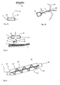
- Fig. 1 presents a known suction dredging method and arrangement, wherein an excavator 9 or similar, controlled by a driver 10, is disposed on a body 8 floating on a water surface 3.
- a suction dredging pump 4 which is connected to the arm 11 of the excavator, pumps sludge 2, which is forced by the pump pressure to move in the tube 5 to the reservoir 7.
- the reservoir is situated on the shore 1, where a barrage 6 prevents the mixture of water and sludge from pouring back.
- the driving force for the pump 4 may be e.g. the hydraulic system of the excavator.
- Fig. 2 presents the operating principle of the dredger according to the present invention.
- the suction dredging pump 4 is connected via a support rod 23 to an unmanned body 21 floating on the water surface 3, which support rod 23 can be used for adjusting the depth position of the pump by means of the hoist 22.
- the hoist 22 can be implemented in various ways within the scope of the same inventive concept, e.g.:
- the motor 20, supplying the driving force to the suction dredging pump 4, is connected next to the pump to the same rod 23.
- a preferred motor type in this application is an electric motor, but other types, e.g. a hydraulic motor, are also possible.
- the electric power for the motor is supplied by an aggregate 26 on the shore via a power cable 25, attached to the sludge tube 5.
- the cable is first connected to the connection box 24 and further to the motor 20. It is also possible to dispose the aggregate on the floating body.
- the sludge is pumped in the tube 5 first to the input edge 28 of the pre-drier 27, which separates water from the sludge to the extent that the pre-dried waste sludge 29 coming out from the output edge of the pre-drier is solid enough to stay in place without risk of said sludge pouring back into the water area.
- the system does not need any reservoir as the known methods do. After being separated from the sludge inside the pre-drier, the water is led back into the water area.
- Figs. 3A and 3B present two principles for how to create the moving force for positioning the floating body within the dredging area. Parts that are not relevant from viewpoint of moving the body are not presented in the figures.
- a rotating wheel 31, connected to the pump 4 has radial teeth or spikes, which when penetrating the sludge 2 create a moving force for the pump and thus also for the floating body.
- the driving motor of the wheel (not presented) may be connected to the connection box 24 e.g. via the same electric power cable 32 as the driving motor of the pump 4.
- two propellers 34, 35 receiving their rotating force from the motors 36, 37, are connected to the floating body 21.
- the floating body can be made to move in the desired direction. It is also possible to control the direction of movement of the floating body with only one propeller that can turn 360° (so-called Azipod).
- Figs. 4A and 4B present two principles for how the control unit of the dredger can be continuously aware of the location of the floating body in the dredging area.
- Fig. 4A presents a known positioning method, wherein a navigator 41 on the floating body 21 has a signal connection 42 to a GPS (Global Positioning System) satellite 43.
- GPS Global Positioning System
- the compass direction ⁇ of the sludge tube 5 and its length L to the reference point 45 on the shore 44 are measured.
- the reference point 45 is preferably the tube transferring station 45, which pushes the tube step by step towards the water area (i.e. increases the length L) according to the progress of the dredging work.
- the positioning method is based on the fact that the pressure inside the tube keeps said tube sufficiently straight for the position of the floating body to be determined with a known vector calculation based on the length and direction of the tube.
- the measurement of the tube length between the floating body and the tube transferring station 45 may be based e.g. on an indirect method, wherein the control unit of the dredger calculates the number of steps by which the length of the tube has been increased. This is possible because the control unit gives all the commands for increasing the steps of the tube length.
- the distance from the dredging pump to the water surface and to the bottom of the water area must be known by the dredger control unit in order to be able to adjust the pump depth position correctly.
- Fig. 5 presents an example of an automatic depth measurement, wherein the control unit 41, placed on the body floating on the water surface, is in e.g. a wireline connection (wire not shown in the figure) with the pressure sensor 51 and with the echo sounder 52, both of which are attached to the motor 20.
- the measuring result of the pressure sensor is directly proportional to the distance between the water surface 3 and the sensor.
- the echo sounder 52 sends an acoustic signal 53, which is reflected back from the bottom, and from this reflection the distance between the sensor and the bottom, possibly also even the depth of the mud 2 level thickness, can be calculated, as is well known.
- the distance from the water surface to the bottom, and the thickness of the mud level may be measured manually e.g. by using a measuring stick in some points within the area to be dredged. This information may then be programmed into the control unit of the dredger, which interpolates the depth information between the known points.
- the sludge, pumped in a tube from the dredging pump on shore, will be pre-dried so that it does not flow back into the water area. This means that at least 50% by the volume of the water contained in the sludge is removed in the pre-dryer.
- Fig. 6 presents an example of the pre-dryer 60, where the input edge 61 is connected to the sludge tube 5.
- the pre-dryer contains a conveying screw 65, which is rotated around its shaft 64 inside a punched conveying tube 63 by a motor 66.
- the sludge is conveyed to the output end 62. Most of the water content of the sludge leaks out from the tube 63 through the conveying tube holes.
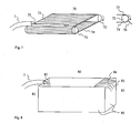
- Fig. 7 presents another example of a pre-dryer 70, which has two rotating prolate rollers 71, 72, and a punched flexible dryer band 77 between them.
- the wet sludge coming from the dredger tube 5 is led onto essentially the whole width of the band e.g. by using a chute 75 on the top side 73 at the input end of the dryer band (roller 71).
- the band conveys the sludge to the output end (roller 72) while most of the sludge water leaks through the holes in the conveying band.
- This separated water can then be collected with a chute (not shown), placed between the top side 73 and underside 74 of the band, in order to lead it back into the water area.
- the pre-dried sludge can be removed from the conveyor band at its output end with a scraper 76.
- Fig. 8 presents another example of the pre-dryer 80, which is a fenced area 86 surrounded by e.g. a flexible material, wherein the wet sludge 82 is led from the tube 5 into the input end 81 and the excess water 85 spills out from the output end 83 through a filter 84, placed at a lower vertical level than the upper edge of the fence 86. While the water drifts from the input end 81 to the output end 83, most of the solid sludge material settles onto the bottom of the pre-dryer. Because the filter 84 prevents most of the remaining fine-grained solid material from coming out of the pre-dryer, the exiting water is quite clear and it can be led back into the water area.
- a fenced area 86 surrounded by e.g. a flexible material
Landscapes
- Engineering & Computer Science (AREA)
- Mining & Mineral Resources (AREA)
- Structural Engineering (AREA)
- General Engineering & Computer Science (AREA)
- Civil Engineering (AREA)
- Mechanical Engineering (AREA)
- Environmental & Geological Engineering (AREA)
- Organic Chemistry (AREA)
- Chemical & Material Sciences (AREA)
- Water Supply & Treatment (AREA)
- Life Sciences & Earth Sciences (AREA)
- Hydrology & Water Resources (AREA)
- Treatment Of Sludge (AREA)
Applications Claiming Priority (1)
| Application Number | Priority Date | Filing Date | Title |
|---|---|---|---|
| FI20115169A FI20115169A0 (fi) | 2011-02-22 | 2011-02-22 | Menetelmä ja laitteisto vesistön pohjan puhdistamiseksi |
Publications (2)
| Publication Number | Publication Date |
|---|---|
| EP2492403A2 true EP2492403A2 (fr) | 2012-08-29 |
| EP2492403A3 EP2492403A3 (fr) | 2012-11-14 |
Family
ID=43629841
Family Applications (1)
| Application Number | Title | Priority Date | Filing Date |
|---|---|---|---|
| EP12156337A Withdrawn EP2492403A3 (fr) | 2011-02-22 | 2012-02-21 | Procédé et appareil de purge des boues du fond d'une pièce d'eau |
Country Status (2)
| Country | Link |
|---|---|
| EP (1) | EP2492403A3 (fr) |
| FI (1) | FI20115169A0 (fr) |
Cited By (16)
| Publication number | Priority date | Publication date | Assignee | Title |
|---|---|---|---|---|
| US20160148711A1 (en) * | 2014-11-21 | 2016-05-26 | Westinghouse Electric Germany Gmbh | Nuclear facility pool cleaning device |
| EP3037588A1 (fr) * | 2015-12-15 | 2016-06-29 | Bibaut Environnement | Procede d'extraction de boues d'une etendue d'eau a hauteur d'eau variable et dispositif associe |
| CN106436800A (zh) * | 2016-09-14 | 2017-02-22 | 滨州市金毅设备有限公司 | 一种水陆两用清淤设备 |
| WO2017181964A1 (fr) * | 2016-04-22 | 2017-10-26 | 密西西比国际水务有限公司 | Procédé et appareil de traitement de rivière noire et odorante |
| CN108678060A (zh) * | 2018-07-13 | 2018-10-19 | 浙江君泰生态科技股份有限公司 | 可移动抽泥装置及其抽泥方法 |
| CN109457751A (zh) * | 2018-11-13 | 2019-03-12 | 四川大学 | 一种绞吸式淤泥清理机 |
| CN111825290A (zh) * | 2020-08-07 | 2020-10-27 | 浙江水利水电学院 | 一种河道生态环境保护修复装置 |
| CN112431161A (zh) * | 2020-11-11 | 2021-03-02 | 中铁二十五局集团第五工程有限公司 | 水下疏浚施工工艺 |
| AU2016329776B2 (en) * | 2015-10-01 | 2021-04-01 | Zodiac Pool Care Europe | Swimming pool cleaning system with image capture device |
| CN112681433A (zh) * | 2020-12-31 | 2021-04-20 | 华北水利水电大学 | 一种河道污水处理用淤泥清理装置 |
| CN113216301A (zh) * | 2021-04-19 | 2021-08-06 | 北京中研建科科技产业发展有限公司 | 一种水利通道除淤设备 |
| CN114411844A (zh) * | 2021-12-24 | 2022-04-29 | 长江勘测规划设计研究有限责任公司 | 用于水利工程的水下清污系统及方法 |
| CN114809158A (zh) * | 2022-03-09 | 2022-07-29 | 中科信德建设有限公司 | 多功能水利施工清淤疏通装置 |
| CN115045359A (zh) * | 2022-06-20 | 2022-09-13 | 中电建十一局工程有限公司 | 一种简易型清淤设备 |
| CN115110597A (zh) * | 2022-07-13 | 2022-09-27 | 连云港港口工程设计研究院有限公司 | 一种河道清淤用水炮车 |
| CN118856105A (zh) * | 2023-11-29 | 2024-10-29 | 浙江省疏浚工程有限公司 | 一种水面长距离环保清淤管道及安装方法 |
Citations (3)
| Publication number | Priority date | Publication date | Assignee | Title |
|---|---|---|---|---|
| JPS5891235A (ja) | 1981-11-20 | 1983-05-31 | Hitachi Techno Eng Co Ltd | 小形砂泥除去装置 |
| DE10212297A1 (de) | 2002-03-20 | 2003-10-09 | Carsten Deny | Schimmbagger zum Fördern eines ein Produkt und Wasser aufweisenden Fördergutes aus einem Gewässer an Land und ein Betriebsverfahren hierzu |
| JP2008223433A (ja) | 2007-03-15 | 2008-09-25 | Toa Harbor Works Co Ltd | 浚渫方法および装置 |
Family Cites Families (8)
| Publication number | Priority date | Publication date | Assignee | Title |
|---|---|---|---|---|
| FR1417581A (fr) * | 1964-12-15 | 1965-11-12 | Dispositif pour évacuer des alluvions déposées dans les lacs artificiels | |
| GB2030733A (en) * | 1978-09-26 | 1980-04-10 | Voith Gmbh J M | Ship Steering Control Device |
| JPH02261598A (ja) * | 1989-03-31 | 1990-10-24 | Hitachi Kiden Kogyo Ltd | 池、堀等のヘドロの処理方法 |
| JP2587791B2 (ja) * | 1994-08-12 | 1997-03-05 | 明 大島 | 溜池などの底床側汚泥除去回収装置 |
| US5656174A (en) * | 1996-02-16 | 1997-08-12 | Solomon Venture | Dredging system and method |
| US6584709B2 (en) * | 2001-06-08 | 2003-07-01 | The United States Of America As Represented By The Secretary Of The Army | Device for removing sludge from the bottom of a lagoon |
| DE102008041323A1 (de) * | 2008-08-19 | 2010-02-25 | Robert Bosch Gmbh | Autonomer Bewässerungsroboter sowie Bewässerungssystem |
| BE1018564A4 (nl) * | 2009-01-12 | 2011-03-01 | Dredging Int | Werkwijze en inrichting voor het aansturen van een mobiele grondbehandelinrichting. |
-
2011
- 2011-02-22 FI FI20115169A patent/FI20115169A0/fi not_active Application Discontinuation
-
2012
- 2012-02-21 EP EP12156337A patent/EP2492403A3/fr not_active Withdrawn
Patent Citations (3)
| Publication number | Priority date | Publication date | Assignee | Title |
|---|---|---|---|---|
| JPS5891235A (ja) | 1981-11-20 | 1983-05-31 | Hitachi Techno Eng Co Ltd | 小形砂泥除去装置 |
| DE10212297A1 (de) | 2002-03-20 | 2003-10-09 | Carsten Deny | Schimmbagger zum Fördern eines ein Produkt und Wasser aufweisenden Fördergutes aus einem Gewässer an Land und ein Betriebsverfahren hierzu |
| JP2008223433A (ja) | 2007-03-15 | 2008-09-25 | Toa Harbor Works Co Ltd | 浚渫方法および装置 |
Cited By (24)
| Publication number | Priority date | Publication date | Assignee | Title |
|---|---|---|---|---|
| US9779842B2 (en) * | 2014-11-21 | 2017-10-03 | Westinghouse Electric Germany Gmbh | Nuclear facility pool cleaning device |
| US20160148711A1 (en) * | 2014-11-21 | 2016-05-26 | Westinghouse Electric Germany Gmbh | Nuclear facility pool cleaning device |
| AU2016329776B2 (en) * | 2015-10-01 | 2021-04-01 | Zodiac Pool Care Europe | Swimming pool cleaning system with image capture device |
| US12173524B2 (en) | 2015-10-01 | 2024-12-24 | Zodiac Pool Care Europe | Swimming pool cleaning system with image capture device |
| US11629516B2 (en) | 2015-10-01 | 2023-04-18 | Zodiac Pool Care Europe | Swimming pool cleaning system with image capture device |
| US11306500B2 (en) | 2015-10-01 | 2022-04-19 | Zodiac Pool Care Europe | Swimming pool cleaning system with image capture device |
| EP3037588A1 (fr) * | 2015-12-15 | 2016-06-29 | Bibaut Environnement | Procede d'extraction de boues d'une etendue d'eau a hauteur d'eau variable et dispositif associe |
| WO2017181964A1 (fr) * | 2016-04-22 | 2017-10-26 | 密西西比国际水务有限公司 | Procédé et appareil de traitement de rivière noire et odorante |
| US10894729B2 (en) | 2016-04-22 | 2021-01-19 | Mississippi International Water Inc. | Method and apparatus for treating polluted and malodorous river |
| CN106436800A (zh) * | 2016-09-14 | 2017-02-22 | 滨州市金毅设备有限公司 | 一种水陆两用清淤设备 |
| CN108678060A (zh) * | 2018-07-13 | 2018-10-19 | 浙江君泰生态科技股份有限公司 | 可移动抽泥装置及其抽泥方法 |
| CN109457751A (zh) * | 2018-11-13 | 2019-03-12 | 四川大学 | 一种绞吸式淤泥清理机 |
| CN111825290A (zh) * | 2020-08-07 | 2020-10-27 | 浙江水利水电学院 | 一种河道生态环境保护修复装置 |
| CN112431161A (zh) * | 2020-11-11 | 2021-03-02 | 中铁二十五局集团第五工程有限公司 | 水下疏浚施工工艺 |
| CN112681433A (zh) * | 2020-12-31 | 2021-04-20 | 华北水利水电大学 | 一种河道污水处理用淤泥清理装置 |
| CN112681433B (zh) * | 2020-12-31 | 2022-03-22 | 华北水利水电大学 | 一种河道污水处理用淤泥清理装置 |
| CN113216301A (zh) * | 2021-04-19 | 2021-08-06 | 北京中研建科科技产业发展有限公司 | 一种水利通道除淤设备 |
| CN113216301B (zh) * | 2021-04-19 | 2022-05-27 | 江苏淮阴水利建设有限公司 | 一种水利通道除淤设备 |
| CN114411844A (zh) * | 2021-12-24 | 2022-04-29 | 长江勘测规划设计研究有限责任公司 | 用于水利工程的水下清污系统及方法 |
| CN114809158A (zh) * | 2022-03-09 | 2022-07-29 | 中科信德建设有限公司 | 多功能水利施工清淤疏通装置 |
| CN114809158B (zh) * | 2022-03-09 | 2023-08-18 | 中科信德建设有限公司 | 多功能水利施工清淤疏通装置 |
| CN115045359A (zh) * | 2022-06-20 | 2022-09-13 | 中电建十一局工程有限公司 | 一种简易型清淤设备 |
| CN115110597A (zh) * | 2022-07-13 | 2022-09-27 | 连云港港口工程设计研究院有限公司 | 一种河道清淤用水炮车 |
| CN118856105A (zh) * | 2023-11-29 | 2024-10-29 | 浙江省疏浚工程有限公司 | 一种水面长距离环保清淤管道及安装方法 |
Also Published As
| Publication number | Publication date |
|---|---|
| EP2492403A3 (fr) | 2012-11-14 |
| FI20115169A0 (fi) | 2011-02-22 |
Similar Documents
| Publication | Publication Date | Title |
|---|---|---|
| EP2492403A2 (fr) | Procédé et appareil de purge des boues du fond d'une pièce d'eau | |
| US20050268499A1 (en) | Method and apparatus for pumping with a dredge | |
| US20040159614A1 (en) | Method and apparatus for cleaning a water area | |
| WO1982000486A1 (fr) | Procede de tranchee a coulis et appareil de construction de murs souterrains | |
| JP7319946B2 (ja) | 浚渫装置と浚渫システム、及び浚渫方法 | |
| US5638620A (en) | Dredging vessel, dredging assembly and method of dredging | |
| US20140338233A1 (en) | Methods, apparatus and systems for pond remediation | |
| EP3333327A1 (fr) | Véhicule de dragage autonome pour draguer un barrage-réservoir | |
| US7089693B2 (en) | Dredging method and apparatus | |
| KR102443356B1 (ko) | 유압식 수중 무인 준설장비 시스템 | |
| US20030154634A1 (en) | Automatic dredge system and method of operation | |
| KR20100136027A (ko) | 부스터선을 이용하여 준설물을 전송하는 준설선 | |
| EP3751057B1 (fr) | Système de transfert de matériau pour un cours d'eau | |
| JPH07268901A (ja) | 浚渫装置 | |
| JP4469627B2 (ja) | 底質泥土回収装置及びその方法 | |
| CN214940523U (zh) | 一种河道淤泥疏浚设备 | |
| JP4835913B2 (ja) | 土運船 | |
| US10519625B2 (en) | Dredger actuated from land | |
| US3975784A (en) | Marine structure | |
| CN209854808U (zh) | 水下履带式削坡设备 | |
| KR200193262Y1 (ko) | 해저면 연약지반 보강용 스프레이 매립 장치 | |
| JP2002038484A (ja) | 水中打設工法および水中打設船 | |
| AU2020202017A1 (en) | Dredging apparatus | |
| KR100366609B1 (ko) | 해저면 연약지반 보강용 스프레이 매립 장치 및 그 공법 | |
| RU2818871C1 (ru) | Устройство для глубоководной добычи илистых отложений и очистки водоемов |
Legal Events
| Date | Code | Title | Description |
|---|---|---|---|
| PUAI | Public reference made under article 153(3) epc to a published international application that has entered the european phase |
Free format text: ORIGINAL CODE: 0009012 |
|
| AK | Designated contracting states |
Kind code of ref document: A2 Designated state(s): AL AT BE BG CH CY CZ DE DK EE ES FI FR GB GR HR HU IE IS IT LI LT LU LV MC MK MT NL NO PL PT RO RS SE SI SK SM TR |
|
| AX | Request for extension of the european patent |
Extension state: BA ME |
|
| PUAL | Search report despatched |
Free format text: ORIGINAL CODE: 0009013 |
|
| AK | Designated contracting states |
Kind code of ref document: A3 Designated state(s): AL AT BE BG CH CY CZ DE DK EE ES FI FR GB GR HR HU IE IS IT LI LT LU LV MC MK MT NL NO PL PT RO RS SE SI SK SM TR |
|
| AX | Request for extension of the european patent |
Extension state: BA ME |
|
| RIC1 | Information provided on ipc code assigned before grant |
Ipc: E02F 5/28 20060101ALI20121008BHEP Ipc: E02F 3/92 20060101ALI20121008BHEP Ipc: E02F 7/06 20060101ALI20121008BHEP Ipc: E02F 3/90 20060101AFI20121008BHEP |
|
| STAA | Information on the status of an ep patent application or granted ep patent |
Free format text: STATUS: THE APPLICATION IS DEEMED TO BE WITHDRAWN |
|
| 18D | Application deemed to be withdrawn |
Effective date: 20130515 |