EP2492136A1 - Seat back structure with lumbar support for vehicle - Google Patents
Seat back structure with lumbar support for vehicle Download PDFInfo
- Publication number
- EP2492136A1 EP2492136A1 EP12156480A EP12156480A EP2492136A1 EP 2492136 A1 EP2492136 A1 EP 2492136A1 EP 12156480 A EP12156480 A EP 12156480A EP 12156480 A EP12156480 A EP 12156480A EP 2492136 A1 EP2492136 A1 EP 2492136A1
- Authority
- EP
- European Patent Office
- Prior art keywords
- lumbar support
- support plate
- seat back
- end portion
- vehicle
- Prior art date
- Legal status (The legal status is an assumption and is not a legal conclusion. Google has not performed a legal analysis and makes no representation as to the accuracy of the status listed.)
- Granted
Links
Images


Classifications
-
- B—PERFORMING OPERATIONS; TRANSPORTING
- B60—VEHICLES IN GENERAL
- B60N—SEATS SPECIALLY ADAPTED FOR VEHICLES; VEHICLE PASSENGER ACCOMMODATION NOT OTHERWISE PROVIDED FOR
- B60N2/00—Seats specially adapted for vehicles; Arrangement or mounting of seats in vehicles
- B60N2/64—Back-rests or cushions
- B60N2/66—Lumbar supports
-
- B—PERFORMING OPERATIONS; TRANSPORTING
- B60—VEHICLES IN GENERAL
- B60N—SEATS SPECIALLY ADAPTED FOR VEHICLES; VEHICLE PASSENGER ACCOMMODATION NOT OTHERWISE PROVIDED FOR
- B60N2/00—Seats specially adapted for vehicles; Arrangement or mounting of seats in vehicles
- B60N2/24—Seats specially adapted for vehicles; Arrangement or mounting of seats in vehicles for particular purposes or particular vehicles
- B60N2/42—Seats specially adapted for vehicles; Arrangement or mounting of seats in vehicles for particular purposes or particular vehicles the seat constructed to protect the occupant from the effect of abnormal g-forces, e.g. crash or safety seats
- B60N2/427—Seats or parts thereof displaced during a crash
- B60N2/42727—Seats or parts thereof displaced during a crash involving substantially rigid displacement
Definitions
- the present invention relates to a structure of a seat back with lumbar support for a vehicle.
- a headrest is provided in the upper part of a seat back as a countermeasure against neck injury (whiplash) in a vehicle occupant in the event of a rear collision.
- neck injury while a headrest alone is not sufficient as a countermeasure against neck injuries.
- the coupling member When the weight of a vehicle occupant acts on an S spring as a reaction to a rear impact, the coupling member extends rearwards, the occupant's back sinks into the seat back, and hence the occupant's head is received and held by the headrest.
- a lumbar support plate 1 which is supported movably in the front/rear direction is provided inside a back frame of a seat back (see reference numeral 20 in Fig. 1 ).
- a clutch mechanism 4 which is capable of rotating a pinion 3, which forms an output member, by means of a rotating operation of a handle shaft 2, is provided in one side frame of the back frame (see reference numeral 20b in Fig. 1 ). Furthermore, a torsion bar 5 is provided as a biasing member which biases the lumbar support plate 1 forwards, one end portion 5a of the torsion bar being supported by the other side frame of the back frame (see reference numeral 20c in Fig. 1 ) and the other end portion 5b of the torsion bar being fixed to a fan-shaped gear (turning member) 7 which is turned by the pinion 3 of the clutch mechanism 4.
- the front/rear position of the other end portion 5b of the torsion bar 5 is adjusted by turning the fan-shaped gear 7 in relation with the rotation of the pinion 3 of the clutch mechanism 4.
- the clutch mechanism 4 (also called a brake mechanism) comprises a brake drum 10, a brake spring 11 which makes pressure contact with the inner wall of the brake drum 10, a core 12 which is formed integrally with the handle shaft 2, and a hook section 3a which is formed integrally with the pinion 3 (see, for example, Japanese Utility Model Application Laid-open No. H7-19562 ).
- the side end portion of the hook section 3a presses a hook section 11a (or 11b) of a brake spring 11 so as to increase the outer diameter of the brake spring 11, against the rotational force from the pinion 3 (the lumbar support plate 1). Consequently, the pressure contact force between the brake spring 11 and the brake drum 10 becomes stronger and rotation of the pinion 3 is impeded (braked state).
- the hook section 11a (or 11b of the brake spring 11 receives force in a direction which compresses the outer diameter from the side end portion 12a of the core 12. Therefore, the pressure contact force becomes less, the handle shaft 2 becomes rotatable (brake released state), and the pinion 3 can be rotated via the brake spring 11 and the hook section 3a.
- the brake spring 11 and the core 12 are incorporated inside a brake drum 10, and the brake drum 10 is fixed by screws 15 to a bracket 14. Furthermore, the handle shaft 2 is coupled to a core 12, and the hook section 3a of the pinion 3 is fitted inside a slot 12a in the core 12 from the outer side of the bracket 14.
- the upper portion of the fan-shaped gear 7 which meshes with the pinion 3 is fixed turnably by a pin member 16 via a plate spring 25 to the upper part of the outer surface of the bracket 14, and the other end portion 5b of the torsion bar 5 is fixed by screws 18 to the fan-shaped gear 7.
- the present invention was devised in order to eliminate the aforementioned problems, an object thereof being to provide a structure of a seat back with lumbar support for a vehicle which avoids increase in both the number of components and weight, by devising a mechanism of a lumbar supporting function so as to serve also as a mechanism providing a countermeasure against neck injury.
- the present invention provides a structure of a seat back with lumbar support for a vehicle, comprising:
- the lumbar support device having a lumbar support function so as to also include a function of providing a neck injury countermeasure in this way, the number of components is reduced, costs are also lowered, and increase in weight can be avoided.
- Fig. 1 shows an internal frame structure of a seat back for a vehicle seat, in which Fig. 1A is a front face diagram and Fig. 1B is a side face cross-sectional diagram.
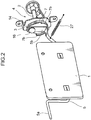
- Fig. 2 is a perspective diagram of a lumbar support plate, a torsion bar and a clutch mechanism.
- the back frame 20 of the seat back is constituted by an inverted U-shaped upper frame 20a, left and right-hand side frames 20b, 20c which are respectively fixed to the left and right-hand portions of the upper frame 20a, and a lower frame 20d which couples the lower portions of the left and right-hand side frames 20b and 20c.
- a pole guide 22 which supports poles 21a of a headrest 21 is fixed to the upper frame 20a.
- a horizontally long rectangular lumbar support plate 1 which is supported movably in the front/rear direction of the vehicle with respect to the back frame 20 is provided in a lower position within the back frame 20, between the left and right-hand side frames 20b and 20c. Furthermore, an S spring 23 is provided in stretched fashion at an upper position between the left and right side frames 20b and 20c.
- a cushion pad is disposed on the upper surface side of the lumbar support plate 1 and the S spring 23, and a seat cushion is composed by covering the over surface portions of these elements with trim.
- a clutch mechanism 4 which is capable of rotating a pinion 3 (called an output member), by means of a rotating operation of a handle shaft 2, is provided in one side frame 20b of the back frame 20.
- a torsion bar 5 is provided as a biasing member which biases the lumbar support plate 1 forwards, one end portion 5a of the torsion bar being supported by the other side frame 20c of the back frame 20 and the other end portion 5b of the torsion bar being linked to a fan-shaped gear (turning member) 7 which is turned by the pinion 3 of the clutch mechanism 4.
- the other end portion 5b of the torsion bar 5 is fixed rather than being linked to the fan-shaped gear (turning member) 7 as in the present invention.
- This linking mechanism and the linking release mechanism are described hereinafter.
- Fig. 3A and Fig. 4A show a state where the lumbar support plate 1 has been set to "strong" (a forward position in the front/rear direction of the vehicle with respect to the back frame 20), and Fig. 3B and Fig.
- FIG. 4B show a state where the lumbar support plate 1 has been set to "weak” (a rear position in the front/rear direction of the vehicle with respect to the position corresponding to the "strong” state).
- reference symbol M indicates the occupant's back.
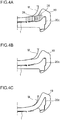
- the clutch mechanism 4 has a similar structure to that of the related art which is illustrated in Fig. 8 and Fig. 9 , and the side end portion of the hook section 3a presses a hook section 11a (or 11b of a brake spring 11 so as to increase the outer diameter of the brake spring 11, against the rotational force from the pinion 3 (the lumbar support plate 1). Consequently, the pressure contact force between the brake spring 11 and the brake drum 10 becomes stronger and rotation of the pinion 3 is impeded (braked state).
- the hook section 11a (or 11b of the brake spring 11 receives force in a direction which compresses the outer diameter from the side end portion 12a of the core 12. Therefore, the pressure contact force becomes less, the handle shaft 2 becomes rotatable (brake released state), and the pinion 3 can be rotated via the brake spring 11 and the hook section 3a.
- a hole 5c in the other end portion 5b of the torsion bar 5 is fitted rotatably and movably in the axial direction (vehicle width direction) into a pinion member 16 which fixes the upper part of the fan-shaped gear 7 turnably to the bracket 14.
- a plate spring (spring member) 25 which biases the other end portion 5b in a direction that contacts the front face of the fan-shaped gear 7 (the upper surface in Fig. 5A ) is interposed between the head portion 16a of the pin member 16 and the other end portion 5b of the torsion bar 5.
- an undulating portion (undulating member) 7a, 7b is provided following the direction of rotation of the other end portion 5b of the torsion bar 5, on the front surface of the fan-shaped gear 7.
- the other end portion 5b of the torsion bar 5 normally fits inside the recess section 7a and is held at an initial position in contact with the front surface of the fan-shaped gear 7 (the bottom surface of the recess portion 7a).
- the front/rear position of the lumbar support plate 1 which is biased forwards by the torsion bar 5 inside the seat back 19 can be adjusted via the clutch mechanism 4 by a rotational operation of the handle shaft 2.
- a lumbar supporting function is obtained by the lumbar support plate 1.
- Fig. 6 is a graph which compares the lumbar support load W and the amount of displacement L of a lumber support plate 1 in the related art and the present embodiment.
- the lumbar support load W is high and the amount of displacement L is small, and therefore it is considered to be difficult to reliably receive the occupant's head on the headrest 21.
- the lumbar support plate 1 since the lumbar support load W becomes low and the amount of displacement L becomes large upon passing the linking release point, then it is considered that the occupant's head can be reliably received by the headrest 21.
- the lumbar support device having a lumbar supporting function so as to also include a function of providing a neck injury countermeasure, the number of components is reduced, costs are also lowered, and increase in weight can be avoided.
- the fan-shaped gear 7 and the pin member 16 which are turned by the pinion 3 are virtually identical to those provided previously, and a plate spring (spring member) 25 and an undulating section (undulating member) 7a, 7b are simply added; hence, the structure is simple and increased costs can be avoided.
- a coil spring (restoring spring member) 27 which restores the lumbar support plate 1 to the initial position (a position where the other end portion 5b of the torsion bar 5 is fitted into the recess section 7a of the fan-shaped gear 7).
- the linking release mechanism temporarily releases the link with the clutch mechanism 4, by causing the other end portion 5b of the torsion bar 5 to rise up onto the projecting section 7b of the fan-shaped gear 7.
- the linking release mechanism can also be constituted by a brake drum 10 of the clutch mechanism 4 and a brake spring 11 which makes pressure contact with the inner wall of the brake drum 10.
- the mechanism is set in such a manner that when a load equal to or greater than a prescribed value is applied to the lumbar support plate 1, the brake spring 11 slips against the inner wall of the brake drum 10 so as to allow rearward movement of the lumbar support plate 1.
- the load of the occupant's weight acting on the lumbar support plate 1 is normally about 200 N to 400 N, whereas when the load of the occupant's weight is about 600 N, then the brake spring 11 slips over the inner wall of the brake drum 10.
- This composition simply involves setting the slip timing of the brake spring 11 with respect to the brake drum 10, and hence there is no requirement for additional components and costs are reduced.
- a cushion pad 28 which supports the upper part of an occupant's back is accommodated to the front side of the S spring 23 and the lumbar support plate 1 in the space between the left and right-hand side frames 20b, 20c in the back frame 20, as indicated partially by the dots in Fig. 4A .
- slits 29 it is possible to form slits 29 extending in the vertical direction in both side portions of the cushion pad 28.
- the upper half of the occupant's body sinks deeply into the seat back 19 together with the occupant's lumbar region, more rapidly, due to the cushion pad 28 between the slits 29.
- the present invention provides a structure of a seat back with lumbar support for a vehicle, comprising:
- the lumbar support device having a lumbar supporting function so as to also include a function of providing a neck injury countermeasure in this way, the number of components is reduced, costs are also lowered, and increase in weight can be avoided.
- the structure of a seat back with lumbar support for a vehicle further comprises:
- the linked state between the lumbar support plate (1) and the handle shaft (2) based on the linking mechanism (4) is temporarily released by the linking release mechanism, in such a manner that rearward movement of the lumbar support plate (1) is permitted.
- the occupant's back sinks into the seat back together with the lumbar support plate (1), and therefore the occupant's head is received reliably by the headrest (21) and a countermeasure to neck injury is obtained.
- the lumbar support device having a lumbar supporting function so as to also include a function of providing a neck injury countermeasure in this way, the number of components is reduced, costs are also lowered, and increase in weight can be avoided.
- the adjustment member in the structure of a seat back with lumbar support for a vehicle, includes a turning member (7) which turns in synchronization with rotation of the output member (3), and the position of the lumbar support plate (1), in the front/rear direction of the vehicle, with respect to the back frame (20) is adjustable by turning of the turning member (7)
- the biasing member includes a torsion bar (5) having one end portion and another end portion in a width direction of the seat back (19), the one end portion (5a) of the torsion bar (5) is linked to one side frame (20c) of the back frame (20), the other end portion (5b) of the torsion bar (5) is linked to the turning member (7) which turns as a result of a rotating operation of the output member (3)
- the linking release mechanism has:
- the biasing member is formed by a torsion bar (5)
- the main constituent elements of the adjustment member are formed by a turning member (7)
- the main constituent elements of the linking release mechanism are formed by a pin member (16), a spring member (25) and an undulating section (7a, 7b) formed in a turning member (7)
- the turning member (7) which is turned by the output member (3) and the pin member (16) are virtually the same as existing components, and in practice, a spring member (25) and an undulating section (7a, 7b) are simply added to these, and hence the structure is simple and the cost is low.
- a restoring spring member (27) which biases the lumbar support plate (1) in a direction that restores the lumbar support plate to the prescribed position is further provided.
- a restoring spring member (27) which restores the lumbar support plate (1) to the initial position, it is possible to automatically restore the lumbar support plate (1) to the initial position, when a load equal to or greater than a prescribed value is not applied. Furthermore, if the lumbar support plate (1) is adjusted to move forwards in a state where the occupant is resting against the seat back, then although the operating load is heavy, the operating load can be reduced by means of the restoring spring (27).
- the clutch mechanism (4) in the structure of a seat back with lumbar support for a vehicle, includes a brake drum (10) and a brake spring (11) which makes pressure contact with an inner wall of this brake drum (10), and the linking release mechanism is set such that, when a load equal to or greater than a prescribed value is applied to the lumbar support plate (1), the brake spring (11) slips against the inner wall of the brake drum (10) so as to allow rearward movement of the lumbar support plate (1).
- the linking release mechanism is constituted by a brake drum (10) and a brake spring (11), and hence the invention simply involves setting the slip timing of the brake spring (11) with respect to the brake drum (10), and therefore additional components are not required and costs are low.
- a cushion pad (28) which supports the upper back (M) of a vehicle occupant is accommodated on a front side of the lumbar support plate (1) in a space between the back frame (20) and left and right-hand side frames (20b, 20c), and slits (29) extending in the vertical direction are formed in both side portions of the cushion pad (28).
- a cushion pad (28) that supports the upper back (M) of an occupant is accommodated to the front side of a lumbar support plate, in a space between a back frame (20) and left and right-hand side frames, and slits (29) extending in the vertical direction are formed in either side portion of the cushion pad (28), the occupant's upper body, together with the lumbar region, sinks deeply into the seat back (19) more rapidly.
- the turning member (7) is formed by a fan-shaped gear which pivots about a pin member (16), a projecting section (7b) which projects inwards in the width direction of the seat back is formed in an outer perimeter edge portion of the fan-shaped gear (7) in a radial direction thereof, and a recess section (7a) which does not project inwards in the width direction is formed in an intermediate portion of the projecting section (7b).
- the linking release mechanism is formed such that, when a load equal to or greater than a prescribed value is applied to the lumbar support plate (1), the other end portion (5b) of the torsion bar (5) deforms elastically inwards in the width direction, rotates about the pin member (16) so as to ride up onto the projecting section (7b) from the recess section (7a) of the fan-shaped gear (7), and moves along the projecting section (7b), thereby permitting rearward movement of the lumbar support plate (1).
Abstract
Description
- The present invention relates to a structure of a seat back with lumbar support for a vehicle.
- In a vehicle, and in particular an automobile, a headrest is provided in the upper part of a seat back as a countermeasure against neck injury (whiplash) in a vehicle occupant in the event of a rear collision. However, a headrest alone is not sufficient as a countermeasure against neck injuries.
- Therefore, it has been proposed to provide a coupling member which extends rearwards only when a load equal to or exceeding a prescribed value is applied, in the coupling portion of a seat back frame with an S spring (a cushion spring which is bent in a continuous plurality of S shapes) (see, for example, Japanese Patent Application Laid-open No.
H7-291005 - When the weight of a vehicle occupant acts on an S spring as a reaction to a rear impact, the coupling member extends rearwards, the occupant's back sinks into the seat back, and hence the occupant's head is received and held by the headrest.
- On the other hand, there have also been proposed to provide a lumbar support plate for supporting an occupant's lumbar region, inside a seat back (see, for example, Japanese Utility Model Application Laid-open No.
H4-107651 - More specifically, as shown in
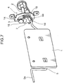
Fig. 7 andFig. 8 , alumbar support plate 1 which is supported movably in the front/rear direction is provided inside a back frame of a seat back (seereference numeral 20 inFig. 1 ). - A
clutch mechanism 4 which is capable of rotating apinion 3, which forms an output member, by means of a rotating operation of ahandle shaft 2, is provided in one side frame of the back frame (seereference numeral 20b inFig. 1 ). Furthermore, atorsion bar 5 is provided as a biasing member which biases thelumbar support plate 1 forwards, oneend portion 5a of the torsion bar being supported by the other side frame of the back frame (seereference numeral 20c inFig. 1 ) and theother end portion 5b of the torsion bar being fixed to a fan-shaped gear (turning member) 7 which is turned by thepinion 3 of theclutch mechanism 4. - As a member for adjusting the front/rear position of the
lumbar support plate 1, the front/rear position of theother end portion 5b of thetorsion bar 5 is adjusted by turning the fan-shaped gear 7 in relation with the rotation of thepinion 3 of theclutch mechanism 4. - As shown in
Fig. 9A , the clutch mechanism 4 (also called a brake mechanism) comprises abrake drum 10, abrake spring 11 which makes pressure contact with the inner wall of thebrake drum 10, acore 12 which is formed integrally with thehandle shaft 2, and ahook section 3a which is formed integrally with the pinion 3 (see, for example, Japanese Utility Model Application Laid-open No.H7-19562 - As shown in
Fig. 9B , the side end portion of thehook section 3a presses ahook section 11a (or 11b) of abrake spring 11 so as to increase the outer diameter of thebrake spring 11, against the rotational force from the pinion 3 (the lumbar support plate 1). Consequently, the pressure contact force between thebrake spring 11 and thebrake drum 10 becomes stronger and rotation of thepinion 3 is impeded (braked state). - Furthermore, in response to a rotational force from the
handle shaft 2 side, thehook section 11a (or 11b of thebrake spring 11 receives force in a direction which compresses the outer diameter from theside end portion 12a of thecore 12. Therefore, the pressure contact force becomes less, thehandle shaft 2 becomes rotatable (brake released state), and thepinion 3 can be rotated via thebrake spring 11 and thehook section 3a. - As shown in
Fig. 8 , in theclutch mechanism 4, thebrake spring 11 and thecore 12 are incorporated inside abrake drum 10, and thebrake drum 10 is fixed byscrews 15 to abracket 14. Furthermore, thehandle shaft 2 is coupled to acore 12, and thehook section 3a of thepinion 3 is fitted inside aslot 12a in thecore 12 from the outer side of thebracket 14. - The upper portion of the fan-
shaped gear 7 which meshes with thepinion 3 is fixed turnably by apin member 16 via aplate spring 25 to the upper part of the outer surface of thebracket 14, and theother end portion 5b of thetorsion bar 5 is fixed byscrews 18 to the fan-shaped gear 7. - However, in Japanese Patent Application Laid-open No.
H7-291005 H4-107651 - Therefore, in order to provide both a lumbar supporting function and a countermeasure against neck injury, it is necessary to provide both a composition having a lumbar supporting function and a composition having a countermeasure against neck injury, and therefore the number of components increases, costs also rise, and the weight also increases.
- The present invention was devised in order to eliminate the aforementioned problems, an object thereof being to provide a structure of a seat back with lumbar support for a vehicle which avoids increase in both the number of components and weight, by devising a mechanism of a lumbar supporting function so as to serve also as a mechanism providing a countermeasure against neck injury.
- In order to resolve the aforementioned problem, the present invention provides a structure of a seat back with lumbar support for a vehicle, comprising:
- a seat back (19);
- a back frame (20),which is provided inside the seat back (19) and which supports a headrest (21); and
- a lumbar support plate (1) which is positioned inside a perimeter of the back frame (20) in a width direction of the vehicle and which is supported by the back frame (20) movably in a front/rear direction of the vehicle,
- the structure further comprising: a linking mechanism which normally holds the lumbar support plate (1) at a prescribed position, in the front/rear direction of the vehicle, with respect to the back frame (20); and a linking release mechanism which permits rearward movement of the lumbar support plate (1) that is in a state of being held at the prescribed position, when a load of a prescribed value or greater is applied to the lumbar support plate (1).
- By means of the composition described above, a lumbar supporting function is obtained by the lumbar support plate (1) which is supported inside the seat back (19).
- Furthermore, when an occupant load of a prescribed value or greater is applied to the lumbar support plate (1) as a reaction to a rear impact, then rearward movement of the lumbar support plate (1) is permitted by the linking release mechanism. By this means, the occupant's back sinks into the seat back (19) together with the lumbar support plate (1), and therefore the occupant's head is received reliably by the headrest (21) and a countermeasure to neck injuries is obtained.
- By devising the lumbar support device having a lumbar support function so as to also include a function of providing a neck injury countermeasure in this way, the number of components is reduced, costs are also lowered, and increase in weight can be avoided.
- These and other objects, features and advantages of the present invention will become apparent upon reading of the following detailed description along with the accompanied drawings.
-
-
Figs. 1A and 1B show an internal frame structure of a frame back of a vehicle seat according to an embodiment of the present invention, in whichFig. 1A is a front view diagram andFig. 1B is a side view cross-sectional diagram; -
Fig. 2 is a perspective diagram of a lumbar support plate, a torsion bar and a clutch mechanism according to an embodiment of the present invention; -
Figs. 3A to 3C show a relationship between a fan-shaped gear according to an embodiment of the present invention and the other end portion of the torsion bar;Fig. 3A is a side view diagram of a state where the lumber support plate is set to "strong";Fig. 3B is a side view diagram of a state where the lumbar support plate is set to "weak"; andFig. 3C is a side view diagram of a state where a load equal to or greater than a prescribed value is applied to the lumbar support plate; -
Figs. 4A to 4C show a relationship between the occupant's back and the lumbar support plate according to an embodiment of the present invention;Fig.4A is a plan view diagram of a state where the lumber support plate is set to "strong";Fig. 4B is a plan view diagram of a state where the lumbar support plate is set to "weak"; andFig. 4C is a plan view diagram of a state where a load equal to or greater than a prescribed value is applied to the lumbar support plate; -
Figs. 5A and 5B show an embodiment of the present invention;Fig. 5A is a side view cross-sectional diagram of a case where the other end portion of the torsion bar has ridden up onto a projecting section of a fan-shaped gear; andFig. 5B is a front view diagram ofFig. 5A ; -
Fig. 6 is a graph comparing the lumbar supporting load and the amount of displacement of the lumbar support plate according to the related art and an embodiment of the present invention; -
Fig. 7 is a perspective diagram of a lumbar support plate, a torsion bar and a clutch mechanism (brake mechanism) according to the related art; -
Fig. 8 is an exploded perspective diagram of a lumbar support plate, a torsion bar and a clutch mechanism (brake mechanism) according to the related art; and -
Figs. 9A and 9B show a clutch mechanism (brake mechanism) according to Japanese Utility Model Application Laid-open No.H7-19562 Fig. 9A is an exploded perspective diagram; andFig. 9B is a plan view cross-sectional diagram. - Hereinbelow, a mode of implementing the present invention is described in detail with reference to the drawings. Parts which have the same composition and action as the prior art are labeled with the same reference numbers and detailed description thereof is omitted here.
-
Fig. 1 shows an internal frame structure of a seat back for a vehicle seat, in whichFig. 1A is a front face diagram andFig. 1B is a side face cross-sectional diagram.Fig. 2 is a perspective diagram of a lumbar support plate, a torsion bar and a clutch mechanism. - The
back frame 20 of the seat back is constituted by an inverted U-shapedupper frame 20a, left and right-hand side frames 20b, 20c which are respectively fixed to the left and right-hand portions of theupper frame 20a, and alower frame 20d which couples the lower portions of the left and right-hand side frames 20b and 20c. - A
pole guide 22 which supportspoles 21a of aheadrest 21 is fixed to theupper frame 20a. - A horizontally long rectangular
lumbar support plate 1 which is supported movably in the front/rear direction of the vehicle with respect to theback frame 20 is provided in a lower position within theback frame 20, between the left and right-hand side frames 20b and 20c. Furthermore, anS spring 23 is provided in stretched fashion at an upper position between the left and right side frames 20b and 20c. - A cushion pad is disposed on the upper surface side of the
lumbar support plate 1 and theS spring 23, and a seat cushion is composed by covering the over surface portions of these elements with trim. - As shown in
Fig. 2 , aclutch mechanism 4 which is capable of rotating a pinion 3 (called an output member), by means of a rotating operation of ahandle shaft 2, is provided in oneside frame 20b of theback frame 20. Furthermore, atorsion bar 5 is provided as a biasing member which biases thelumbar support plate 1 forwards, oneend portion 5a of the torsion bar being supported by theother side frame 20c of theback frame 20 and theother end portion 5b of the torsion bar being linked to a fan-shaped gear (turning member) 7 which is turned by thepinion 3 of theclutch mechanism 4. In the related art shown inFig. 7 , theother end portion 5b of thetorsion bar 5 is fixed rather than being linked to the fan-shaped gear (turning member) 7 as in the present invention. This linking mechanism and the linking release mechanism are described hereinafter. - As a member for adjusting the position of the
lumbar support plate 1 with respect to theback frame 20 in the front/rear direction of the vehicle, similarly to the related art, the front/rear position of theother end portion 5b of thetorsion bar 5 is adjusted by turning the fan-shapedgear 7 in relation with the rotation of thepinion 3 of theclutch mechanism 4.Fig. 3A andFig. 4A show a state where thelumbar support plate 1 has been set to "strong" (a forward position in the front/rear direction of the vehicle with respect to the back frame 20), andFig. 3B andFig. 4B show a state where thelumbar support plate 1 has been set to "weak" (a rear position in the front/rear direction of the vehicle with respect to the position corresponding to the "strong" state). InFig. 4A to Fig. 4C , reference symbol M indicates the occupant's back. - Furthermore, the
clutch mechanism 4 has a similar structure to that of the related art which is illustrated inFig. 8 andFig. 9 , and the side end portion of thehook section 3a presses ahook section 11a (or 11b of abrake spring 11 so as to increase the outer diameter of thebrake spring 11, against the rotational force from the pinion 3 (the lumbar support plate 1). Consequently, the pressure contact force between thebrake spring 11 and thebrake drum 10 becomes stronger and rotation of thepinion 3 is impeded (braked state). - Furthermore, in response to a rotational force from the
handle shaft 2 side, thehook section 11a (or 11b of thebrake spring 11 receives force in a direction which compresses the outer diameter from theside end portion 12a of thecore 12. Therefore, the pressure contact force becomes less, thehandle shaft 2 becomes rotatable (brake released state), and thepinion 3 can be rotated via thebrake spring 11 and thehook section 3a. - As shown in
Fig. 5A , ahole 5c in theother end portion 5b of thetorsion bar 5 is fitted rotatably and movably in the axial direction (vehicle width direction) into apinion member 16 which fixes the upper part of the fan-shapedgear 7 turnably to thebracket 14. - A plate spring (spring member) 25 which biases the
other end portion 5b in a direction that contacts the front face of the fan-shaped gear 7 (the upper surface inFig. 5A ) is interposed between thehead portion 16a of thepin member 16 and theother end portion 5b of thetorsion bar 5. - As shown in
Fig. 5B , an undulating portion (undulating member) 7a, 7b is provided following the direction of rotation of theother end portion 5b of thetorsion bar 5, on the front surface of the fan-shapedgear 7. Theother end portion 5b of thetorsion bar 5 normally fits inside therecess section 7a and is held at an initial position in contact with the front surface of the fan-shaped gear 7 (the bottom surface of therecess portion 7a). - In this state, the position of the
other end portion 5b of thetorsion bar 5 in the front/rear direction of the vehicle is adjusted in relation with the turning of the fan-shaped gear 7 (linking mechanism). - If a load of a prescribed value or greater is applied to the
lumbar support plate 1, then as shown inFig. 3C andFig. 4C , theother end portion 5b of thetorsion bar 5 rides up onto the projectingsection 7b while moving in the axial direction (the vehicle width direction) away from the fan-shapedgear 7, against the biasing force of the plate spring 25 (see double-dotted broken line inFig. 5B ), thereby temporarily releasing the linking with theclutch mechanism 4 and allowing further rearward movement beyond the region of therecess section 7a of the lumbar support plate 1 (linking release mechanism). - As described above, according to the composition of the seat back having a lumbar support for a vehicle, the front/rear position of the
lumbar support plate 1 which is biased forwards by thetorsion bar 5 inside the seat back 19 (seeFig. 4 ) can be adjusted via theclutch mechanism 4 by a rotational operation of thehandle shaft 2. By this means, a lumbar supporting function is obtained by thelumbar support plate 1. - Furthermore, if an occupant load equal to or greater than a prescribed value is applied to the
lumbar support plate 1 as a reaction to a rear impact, then theother end portion 5b of thetorsion bar 5 rides up onto the projectingsection 7b while moving in the axial direction (vehicle width direction) away from the fan-shapedgear 7, against the biasing force of theplate spring 25. By this means, further rearward movement is allowed beyond the region of therecess section 7a of thelumbar support plate 1, since the linking with theclutch mechanism 4 is temporarily released. - By this means, as shown in
Fig. 4C , the occupant's back sinks into the seat back 19 together with thelumbar support plate 1, and therefore the occupant's head is received reliably by theheadrest 21 and a countermeasure to neck injury is obtained. -
Fig. 6 is a graph which compares the lumbar support load W and the amount of displacement L of alumber support plate 1 in the related art and the present embodiment. - In a state where the
lumbar support plate 1 is set to "weak" or "strong", the relationship between the lumbar support load W and the amount of displacement L of thelumbar support plate 1 of the related art and the present embodiment are the same, as shown inFig. 6 . - When an occupant's weight equal to or exceeding a prescribed value is applied to the
lumbar support plate 1 as a reaction to a rear impact, in alumbar support plate 1 according to the related art, the lumbar support load W is high and the amount of displacement L is small, and therefore it is considered to be difficult to reliably receive the occupant's head on theheadrest 21. - On the other hand, with the
lumbar support plate 1 according to the present embodiment, since the lumbar support load W becomes low and the amount of displacement L becomes large upon passing the linking release point, then it is considered that the occupant's head can be reliably received by theheadrest 21. - By devising the lumbar support device having a lumbar supporting function so as to also include a function of providing a neck injury countermeasure, the number of components is reduced, costs are also lowered, and increase in weight can be avoided.
- Furthermore, in the
lumbar support plate 1 of a torsion bar type, the fan-shapedgear 7 and thepin member 16 which are turned by thepinion 3 are virtually identical to those provided previously, and a plate spring (spring member) 25 and an undulating section (undulating member) 7a, 7b are simply added; hence, the structure is simple and increased costs can be avoided. - In the embodiment described above, as shown in
Fig. 2 , it is possible to provide a coil spring (restoring spring member) 27 which restores thelumbar support plate 1 to the initial position (a position where theother end portion 5b of thetorsion bar 5 is fitted into therecess section 7a of the fan-shaped gear 7). - By means of this composition, when a load equal to or exceeding the prescribed value is not applied, then it is possible to automatically return the
lumbar support plate 1 to the initial position. Furthermore, if thelumbar support plate 1 is adjusted to move forwards in a state where the occupant is resting against the seat back 19, then although the operating load is heavy, the operating load can be reduced by means of thecoil spring 27. - The linking release mechanism according to the embodiment described above temporarily releases the link with the
clutch mechanism 4, by causing theother end portion 5b of thetorsion bar 5 to rise up onto the projectingsection 7b of the fan-shapedgear 7. - On the other hand, the linking release mechanism can also be constituted by a
brake drum 10 of theclutch mechanism 4 and abrake spring 11 which makes pressure contact with the inner wall of thebrake drum 10. - In other words, the mechanism is set in such a manner that when a load equal to or greater than a prescribed value is applied to the
lumbar support plate 1, thebrake spring 11 slips against the inner wall of thebrake drum 10 so as to allow rearward movement of thelumbar support plate 1. - More specifically, the load of the occupant's weight acting on the
lumbar support plate 1 is normally about 200 N to 400 N, whereas when the load of the occupant's weight is about 600 N, then thebrake spring 11 slips over the inner wall of thebrake drum 10. - This composition simply involves setting the slip timing of the
brake spring 11 with respect to thebrake drum 10, and hence there is no requirement for additional components and costs are reduced. - In the embodiment described above, a
cushion pad 28 which supports the upper part of an occupant's back is accommodated to the front side of theS spring 23 and thelumbar support plate 1 in the space between the left and right-hand side frames 20b, 20c in theback frame 20, as indicated partially by the dots inFig. 4A . As shown inFig. 1A , it is possible to formslits 29 extending in the vertical direction in both side portions of thecushion pad 28. - By this means, the upper half of the occupant's body sinks deeply into the seat back 19 together with the occupant's lumbar region, more rapidly, due to the
cushion pad 28 between theslits 29. - The present invention provides a structure of a seat back with lumbar support for a vehicle, comprising:
- a seat back (19);
- a back frame (20),which is provided inside the seat back (19) and which supports a headrest (21); and
- a lumbar support plate (1) which is positioned inside a perimeter of the back frame (20) in a width direction of the vehicle and which is supported by the back frame (20) movably in a front/rear direction of the vehicle,
- the structure further comprising: a linking mechanism which normally holds the lumbar support plate (1) at a prescribed position, in the front/rear direction of the vehicle, with respect to the back frame (20); and a linking release mechanism which permits rearward movement of the lumbar support plate (1) that is in a state of being held at the prescribed position, when a load of a prescribed value or greater is applied to the lumbar support plate (1).
- By means of the composition described above, a lumbar supporting function is obtained by the lumbar support plate (1) which is supported inside the seat back (19).
- Furthermore, when an occupant load of a prescribed value or greater is applied to the lumbar support plate (1) as a reaction to a rear impact, then rearward movement of the lumbar support plate (1) is permitted by the linking release mechanism. By this means, the occupant's back sinks into the seat back (19) together with the lumbar support plate (1), and therefore the occupant's head is received reliably by the headrest (21) and a countermeasure to neck injury is obtained.
- By devising the lumbar support device having a lumbar supporting function so as to also include a function of providing a neck injury countermeasure in this way, the number of components is reduced, costs are also lowered, and increase in weight can be avoided.
- In one aspect of the present invention, the structure of a seat back with lumbar support for a vehicle further comprises:
- a biasing member (5) which biases the lumbar support plate (1) in the direction of the prescribed position; and
- a handle shaft (2) which can perform a rotating operation and which is provided on one side frame (20b) of the back frame (20), wherein
- the linking mechanism has:
- a clutch mechanism (4) which is capable of transmitting rotation of the handle shaft (2) to the output member (3); and
- an adjustment member which is capable of adjusting the front/rear position of the lumbar support plate (1) with respect to the back frame (20), in relation with the output member (3), and
- the linking release mechanism temporarily releases a state of linkage between the lumbar support plate (1) and the handle shaft (2) established by the linking mechanism (4), thereby permitting rearward movement of the lumbar support plate (1), when a load equal to or greater than a prescribed value is applied to the lumbar support plate (1).
- In the composition described above, it is possible to adjust the position, in the front/rear direction of the vehicle, of the lumbar support plate (1) which is biased forwards in the seat back, via the clutch mechanism (4), by means of a rotational operation of the handle shaft (2). By this means, a lumbar supporting function is obtained in the lumbar support plate (1).
- Furthermore, when an occupant load equal to or greater than a prescribed value is applied to the lumbar support plate (1) as a reaction to a rear impact, the linked state between the lumbar support plate (1) and the handle shaft (2) based on the linking mechanism (4) is temporarily released by the linking release mechanism, in such a manner that rearward movement of the lumbar support plate (1) is permitted. By this means, the occupant's back sinks into the seat back together with the lumbar support plate (1), and therefore the occupant's head is received reliably by the headrest (21) and a countermeasure to neck injury is obtained.
- By devising the lumbar support device having a lumbar supporting function so as to also include a function of providing a neck injury countermeasure in this way, the number of components is reduced, costs are also lowered, and increase in weight can be avoided.
- Moreover, in a further aspect of the present invention, in the structure of a seat back with lumbar support for a vehicle,
the adjustment member includes a turning member (7) which turns in synchronization with rotation of the output member (3), and the position of the lumbar support plate (1), in the front/rear direction of the vehicle, with respect to the back frame (20) is adjustable by turning of the turning member (7),
the biasing member includes a torsion bar (5) having one end portion and another end portion in a width direction of the seat back (19),
the one end portion (5a) of the torsion bar (5) is linked to one side frame (20c) of the back frame (20),
the other end portion (5b) of the torsion bar (5) is linked to the turning member (7) which turns as a result of a rotating operation of the output member (3),
the linking release mechanism has: - a pin member (16) which fits the other end portion (5b) of the torsion bar (5) into the turning member (7) swingably and movably in the width direction of the seat back; and
- a spring member (25) which biases the other end portion (5b) of the torsion bar in a direction to make contact with a bottom surface of a recess section (7a) of an undulating section (7a, 7b) which is formed in the turning member (7),
- the other end portion (5b) of the torsion bar (5) is normally held inside the recess section (7a) of the undulating section, and
- the other end portion (5b) of the torsion bar (5) is moved in a width direction to be away from the recess section (7a) of the turning member (7) against an biasing force of the spring member (25), thereby allowing rearward movement of the lumbar support plate (1), when a load equal to or greater than a prescribed value is applied to the lumbar support plate (1).
- In the composition described above, by adopting a composition in which the biasing member is formed by a torsion bar (5), the main constituent elements of the adjustment member are formed by a turning member (7), and the main constituent elements of the linking release mechanism are formed by a pin member (16), a spring member (25) and an undulating section (7a, 7b) formed in a turning member (7), then in a torsion bar of lumbar support plate (1), the turning member (7) which is turned by the output member (3) and the pin member (16) are virtually the same as existing components, and in practice, a spring member (25) and an undulating section (7a, 7b) are simply added to these, and hence the structure is simple and the cost is low.
- In one aspect of the present invention, in the structure of a seat back with lumbar support for a vehicle, a restoring spring member (27) which biases the lumbar support plate (1) in a direction that restores the lumbar support plate to the prescribed position is further provided.
- Furthermore, by providing a restoring spring member (27) which restores the lumbar support plate (1) to the initial position, it is possible to automatically restore the lumbar support plate (1) to the initial position, when a load equal to or greater than a prescribed value is not applied. Furthermore, if the lumbar support plate (1) is adjusted to move forwards in a state where the occupant is resting against the seat back, then although the operating load is heavy, the operating load can be reduced by means of the restoring spring (27).
- In a further aspect of the present invention, in the structure of a seat back with lumbar support for a vehicle,
the clutch mechanism (4) includes a brake drum (10) and a brake spring (11) which makes pressure contact with an inner wall of this brake drum (10), and
the linking release mechanism is set such that, when a load equal to or greater than a prescribed value is applied to the lumbar support plate (1), the brake spring (11) slips against the inner wall of the brake drum (10) so as to allow rearward movement of the lumbar support plate (1). - In the composition described above, since the linking release mechanism is constituted by a brake drum (10) and a brake spring (11), and hence the invention simply involves setting the slip timing of the brake spring (11) with respect to the brake drum (10), and therefore additional components are not required and costs are low.
- In one aspect of the present invention, in the structure of a seat back with lumbar support for a vehicle, a cushion pad (28) which supports the upper back (M) of a vehicle occupant is accommodated on a front side of the lumbar support plate (1) in a space between the back frame (20) and left and right-hand side frames (20b, 20c), and slits (29) extending in the vertical direction are formed in both side portions of the cushion pad (28).
- By adopting a composition in which a cushion pad (28) that supports the upper back (M) of an occupant is accommodated to the front side of a lumbar support plate, in a space between a back frame (20) and left and right-hand side frames, and slits (29) extending in the vertical direction are formed in either side portion of the cushion pad (28), the occupant's upper body, together with the lumbar region, sinks deeply into the seat back (19) more rapidly.
- In yet a further aspect of the present invention, in the structure of a seat back with lumbar support for a vehicle, the turning member (7) is formed by a fan-shaped gear which pivots about a pin member (16), a projecting section (7b) which projects inwards in the width direction of the seat back is formed in an outer perimeter edge portion of the fan-shaped gear (7) in a radial direction thereof, and a recess section (7a) which does not project inwards in the width direction is formed in an intermediate portion of the projecting section (7b).
- In yet a further aspect of the present invention, in the structure of a seat back with lumbar support for a vehicle, the linking release mechanism is formed such that, when a load equal to or greater than a prescribed value is applied to the lumbar support plate (1), the other end portion (5b) of the torsion bar (5) deforms elastically inwards in the width direction, rotates about the pin member (16) so as to ride up onto the projecting section (7b) from the recess section (7a) of the fan-shaped gear (7), and moves along the projecting section (7b), thereby permitting rearward movement of the lumbar support plate (1).
- This application is based on Japanese Patent Application Serial No.
2011-041248 - Although the present invention has been fully described by way of example with reference to the accompanying drawings, it is to be understood that various changes and modifications will be apparent to those skilled in the art. Therefore, unless otherwise such changes and modifications depart from the scope of the present invention hereinafter defined, they should be construed as being included therein.
Claims (8)
- A structure of a seat back with lumbar support for a vehicle, comprising:a seat back (19);a back frame (20), which is provided inside the seat back and which supports a headrest (21); anda lumbar support plate (1) which is positioned inside a perimeter of the back frame in a width direction of the vehicle and which is supported by the back frame movably in a front/rear direction of the vehicle,the structure further comprising:a linking mechanism which normally holds the lumbar support plate at a prescribed position, in the front/rear direction of the vehicle, with respect to the back frame; anda linking release mechanism which permits rearward movement of the lumbar support plate that is in a state of being held at the prescribed position, when a load of a prescribed value or greater is applied to the lumbar support plate.
- The structure of a seat back with lumbar support for a vehicle according to claim 1, further comprising:a biasing member (5) which biases the lumbar support plate in the direction of the prescribed position; anda handle shaft (2) which can perform a rotating operation and which is provided on one side frame of the back frame, whereinthe linking mechanism having:a clutch mechanism (4) which is capable of transmitting rotation of the handle shaft to an output member (3); andan adjustment member which is capable of adjusting the front/rear position of the lumbar support plate with respect to the back frame, in relation with the output member, andthe linking release mechanism temporarily releases a state of linkage between the lumbar support plate and the handle shaft established by the linking mechanism, thereby permitting rearward movement of the lumbar support plate, when a load equal to or greater than a prescribed value is applied to the lumbar support plate.
- The structure of a seat back with lumbar support for a vehicle according to claim 2, wherein the adjustment member comprises a turning member (7) which turns in synchronization with rotation of the output member (3), and the position of the lumbar support plate, in the front/rear direction of the vehicle, with respect to the back frame is adjustable by turning of the turning member.
the biasing member includes a torsion bar (5) having one end portion and another end portion in a width direction of the seat back,
the one end portion (5a) of the torsion bar is linked to one side frame (20c) of the back frame,
the other end portion (5b) of the torsion bar is linked to the turning member (7) which turns as a result of a rotating operation of the output member,
the linking release mechanism having:a pin member (16) which fits the other end portion of the torsion bar into the turning member (7) swingably and movably in the width direction of the seat back; anda spring member (25) which biases the other end portion of the torsion bar in a direction to make contact with a bottom surface of a recess section (7a) of an undulating section (7a,7b), formed in the turning member,the other end portion (5b) of the torsion bar (5) is normally held inside the recess section (7a) of the undulating section (7a,7b), andthe other end portion (5b) of the torsion bar (5) is moved in a width direction to be away from the recess section (7a) of the turning member (7) against a biasing force of the spring member (25), thereby allowing rearward movement of the lumbar support plate (1), when a load equal to or greater than a prescribed value is applied to the lumbar support plate. - The structure of a seat back with lumbar support for a vehicle according to any one of claims 1 to 3, further comprising a restoring spring member (27) which biases the lumbar support plate in a direction that restores the lumbar support plate to the prescribed position.
- The structure of a seat back with lumbar support for a vehicle according to claim 2, wherein
the clutch mechanism (4) includes a brake drum (10) and a brake spring (11) which makes pressure contact with an inner wall of this brake drum, and
the linking release mechanism is set such that, when a load equal to or greater than a prescribed value is applied to the lumbar support plate, the brake spring slips against the inner wall of the brake drum so as to allow rearward movement of the lumbar support plate. - The structure of a seat back with lumbar support for a vehicle according to any one of claims 1 to 5, wherein a cushion pad which supports the upper back of a vehicle occupant is accommodated on a front side of the lumbar support plate in a space between the back frame and left and right-hand side frames, and slits extending in the vertical direction are formed in both side portions of the cushion pad.
- The structure of a seat back with lumbar support for a vehicle according to claim 3, wherein the turning member (7) is formed by a fan-shaped gear which pivots about a pin member (16), a projecting section (7b) which projects inwards in the width direction of the seat back is formed in an outer perimeter edge portion of the fan-shaped gear in a radial direction thereof, and a recess section (7a) which does not project inwards in the width direction is formed in an intermediate portion of the projecting section (7b).
- The structure of a seat back with lumbar support for a vehicle according to claim 6, wherein the linking release mechanism is formed such that, when a load equal to or greater than a prescribed value is applied to the lumbar support plate, the other end portion (5b) of the torsion bar (5) deforms elastically inwards in the width direction, rotates about the pin member (16) so as to ride up onto the projecting section (7b) from the recess section (7a) of the fan-shaped gear (7), and moves along the projecting section (7b), thereby permitting rearward movement of the lumbar support plate (1).
Applications Claiming Priority (1)
| Application Number | Priority Date | Filing Date | Title |
|---|---|---|---|
| JP2011041248A JP5738626B2 (en) | 2011-02-28 | 2011-02-28 | Seat back structure with lumbar support for vehicles |
Publications (2)
| Publication Number | Publication Date |
|---|---|
| EP2492136A1 true EP2492136A1 (en) | 2012-08-29 |
| EP2492136B1 EP2492136B1 (en) | 2014-04-09 |
Family
ID=45656391
Family Applications (1)
| Application Number | Title | Priority Date | Filing Date |
|---|---|---|---|
| EP12156480.1A Not-in-force EP2492136B1 (en) | 2011-02-28 | 2012-02-22 | Seat back structure with lumbar support for vehicle |
Country Status (4)
| Country | Link |
|---|---|
| US (1) | US8651575B2 (en) |
| EP (1) | EP2492136B1 (en) |
| JP (1) | JP5738626B2 (en) |
| CN (1) | CN102649407B (en) |
Families Citing this family (9)
| Publication number | Priority date | Publication date | Assignee | Title |
|---|---|---|---|---|
| JP5654273B2 (en) * | 2009-09-04 | 2015-01-14 | デルタ工業株式会社 | Structure of vehicle seat back frame |
| KR101468703B1 (en) * | 2014-04-17 | 2014-12-05 | 주식회사 다원체어스 | Back of chair |
| EP3145752B1 (en) | 2014-05-19 | 2021-01-20 | Milsco, LLC | Adjustable seat occupant support assembly |
| KR101664071B1 (en) * | 2015-06-19 | 2016-10-10 | 현대자동차 주식회사 | Lumbar support apparatus for vehicles |
| US10463153B2 (en) * | 2016-06-09 | 2019-11-05 | Steelcase Inc. | Seating arrangement |
| JP6766695B2 (en) * | 2017-03-03 | 2020-10-14 | トヨタ紡織株式会社 | Vehicle seat |
| KR20200123569A (en) * | 2019-04-22 | 2020-10-30 | 현대자동차주식회사 | Lumber support device for seat of vehicle |
| KR102102950B1 (en) * | 2019-12-26 | 2020-04-21 | 주식회사 금창 | Lumber support for vehicle seat |
| JP7359704B2 (en) * | 2020-01-17 | 2023-10-11 | トヨタ自動車株式会社 | Car seat device |
Citations (5)
| Publication number | Priority date | Publication date | Assignee | Title |
|---|---|---|---|---|
| JPH04107651U (en) | 1991-02-27 | 1992-09-17 | 株式会社タチエス | Lumbar support device |
| JPH0719562U (en) | 1993-09-16 | 1995-04-07 | シロキ工業株式会社 | Brake mechanism |
| JPH07291005A (en) | 1994-04-27 | 1995-11-07 | Daihatsu Motor Co Ltd | Seat for automobile |
| WO1996033640A1 (en) * | 1995-04-24 | 1996-10-31 | L & P Property Management Company | Lumbar support structure for automotive vehicle |
| US20100187874A1 (en) * | 2009-01-27 | 2010-07-29 | Toyota Boshoku Kabushiki Kaisha | Internal structure of seatback connected to active headrest |
Family Cites Families (20)
| Publication number | Priority date | Publication date | Assignee | Title |
|---|---|---|---|---|
| US3807794A (en) * | 1972-12-29 | 1974-04-30 | Ford Motor Co | Lumbar support mechanism |
| US3973797A (en) * | 1975-03-31 | 1976-08-10 | Deere & Company | Seat backrest having an adjustable lumbar support |
| GB2149295B (en) * | 1983-09-30 | 1987-04-29 | Tachikawa Spring Co | A lumbar support device |
| US4564235A (en) * | 1984-11-09 | 1986-01-14 | Tachikawa Spring Co., Ltd. | Lumbar support device |
| JPS61131961U (en) * | 1985-02-05 | 1986-08-18 | ||
| US4725095A (en) * | 1986-07-11 | 1988-02-16 | Johnson Service Company | Vehicle seat with mechanical lumbar support having two degrees of freedom |
| JPH0415077Y2 (en) * | 1987-06-30 | 1992-04-06 | ||
| JPH061004Y2 (en) * | 1989-07-31 | 1994-01-12 | 池田物産株式会社 | Lumbar support device |
| JPH04107651A (en) | 1990-08-28 | 1992-04-09 | Yokogawa Electric Corp | Data extracting method |
| US5087098A (en) * | 1990-09-25 | 1992-02-11 | Tachi-S Co., Ltd. | Lumbar support device |
| JP2533364Y2 (en) * | 1990-09-28 | 1997-04-23 | シロキ工業株式会社 | Sheet |
| JP2701675B2 (en) * | 1992-09-24 | 1998-01-21 | アイシン精機株式会社 | Lumber support device |
| US5286087A (en) * | 1992-11-09 | 1994-02-15 | Hoover Universal, Inc. | Seat assembly with lumbar support mechanism |
| JPH0719562A (en) | 1993-07-02 | 1995-01-20 | Matsushita Refrig Co Ltd | Air conditioner |
| JP3112795B2 (en) * | 1994-05-30 | 2000-11-27 | シロキ工業株式会社 | Lumber support |
| US5588703A (en) * | 1995-10-12 | 1996-12-31 | Tachi-S Co., Ltd. | Lumbar support device for vehicle seat |
| JP4526882B2 (en) * | 2004-06-25 | 2010-08-18 | 株式会社東洋シート | Vehicle seat |
| EP2050617B1 (en) * | 2007-10-17 | 2015-12-09 | ELASIS - Società Consortile per Azioni | Backrest of a vehicle seat |
| JP2009248958A (en) * | 2008-04-11 | 2009-10-29 | Nhk Spring Co Ltd | Vehicle seat device |
| CN201509924U (en) * | 2009-09-27 | 2010-06-23 | 蔡国良 | Backrest of chair |
-
2011
- 2011-02-28 JP JP2011041248A patent/JP5738626B2/en not_active Expired - Fee Related
-
2012
- 2012-02-22 EP EP12156480.1A patent/EP2492136B1/en not_active Not-in-force
- 2012-02-23 US US13/403,216 patent/US8651575B2/en not_active Expired - Fee Related
- 2012-02-27 CN CN201210045474.9A patent/CN102649407B/en not_active Expired - Fee Related
Patent Citations (5)
| Publication number | Priority date | Publication date | Assignee | Title |
|---|---|---|---|---|
| JPH04107651U (en) | 1991-02-27 | 1992-09-17 | 株式会社タチエス | Lumbar support device |
| JPH0719562U (en) | 1993-09-16 | 1995-04-07 | シロキ工業株式会社 | Brake mechanism |
| JPH07291005A (en) | 1994-04-27 | 1995-11-07 | Daihatsu Motor Co Ltd | Seat for automobile |
| WO1996033640A1 (en) * | 1995-04-24 | 1996-10-31 | L & P Property Management Company | Lumbar support structure for automotive vehicle |
| US20100187874A1 (en) * | 2009-01-27 | 2010-07-29 | Toyota Boshoku Kabushiki Kaisha | Internal structure of seatback connected to active headrest |
Also Published As
| Publication number | Publication date |
|---|---|
| US20120217778A1 (en) | 2012-08-30 |
| JP2012176166A (en) | 2012-09-13 |
| CN102649407B (en) | 2016-08-03 |
| EP2492136B1 (en) | 2014-04-09 |
| US8651575B2 (en) | 2014-02-18 |
| JP5738626B2 (en) | 2015-06-24 |
| CN102649407A (en) | 2012-08-29 |
Similar Documents
| Publication | Publication Date | Title |
|---|---|---|
| EP2492136B1 (en) | Seat back structure with lumbar support for vehicle | |
| EP2295288B1 (en) | Vehicle seat | |
| EP1522452B1 (en) | Automobile seat | |
| EP1203692B1 (en) | Vehicle seat back assembly | |
| JP6615596B2 (en) | Automotive seat cushion extension device | |
| JP5394036B2 (en) | Vehicle seat | |
| US20080012402A1 (en) | Seat back structure of vehicle seat | |
| EP2412570A2 (en) | Seat back device | |
| KR101015447B1 (en) | Active headrest assembly for vehicles | |
| US6840560B2 (en) | Vehicular seat assembly having a movable headrest and a vehicle which incorporates the vehicular seat assembly | |
| EP1953036B1 (en) | Automobile seat | |
| JP5112736B2 (en) | Vehicle seat | |
| JP2001026232A (en) | Seat device for vehicle | |
| US8029057B2 (en) | Clutch mechanism for vehicle seat | |
| JP2008074295A (en) | Vehicle seat | |
| JP6557061B2 (en) | Vehicle seat | |
| JP5044156B2 (en) | Vehicle seat with headrest | |
| KR101946305B1 (en) | Anti-skid headrest | |
| JP2008254721A (en) | Vehicular seat | |
| KR20150077502A (en) | Automatic headrest | |
| KR102083173B1 (en) | Folding headrest for vehicle | |
| EP2463140B1 (en) | Vehicle seat | |
| WO2011112123A1 (en) | A backrest support mechanism | |
| KR20020051684A (en) | Tilting-device of headrest for automobile | |
| JP2010125919A (en) | Headrest for vehicle seat |
Legal Events
| Date | Code | Title | Description |
|---|---|---|---|
| PUAI | Public reference made under article 153(3) epc to a published international application that has entered the european phase |
Free format text: ORIGINAL CODE: 0009012 |
|
| AK | Designated contracting states |
Kind code of ref document: A1 Designated state(s): AL AT BE BG CH CY CZ DE DK EE ES FI FR GB GR HR HU IE IS IT LI LT LU LV MC MK MT NL NO PL PT RO RS SE SI SK SM TR |
|
| AX | Request for extension of the european patent |
Extension state: BA ME |
|
| 17P | Request for examination filed |
Effective date: 20121122 |
|
| RIC1 | Information provided on ipc code assigned before grant |
Ipc: B60N 2/427 20060101AFI20130801BHEP Ipc: B60N 2/66 20060101ALI20130801BHEP |
|
| GRAP | Despatch of communication of intention to grant a patent |
Free format text: ORIGINAL CODE: EPIDOSNIGR1 |
|
| INTG | Intention to grant announced |
Effective date: 20131001 |
|
| GRAS | Grant fee paid |
Free format text: ORIGINAL CODE: EPIDOSNIGR3 |
|
| GRAA | (expected) grant |
Free format text: ORIGINAL CODE: 0009210 |
|
| AK | Designated contracting states |
Kind code of ref document: B1 Designated state(s): AL AT BE BG CH CY CZ DE DK EE ES FI FR GB GR HR HU IE IS IT LI LT LU LV MC MK MT NL NO PL PT RO RS SE SI SK SM TR |
|
| REG | Reference to a national code |
Ref country code: GB Ref legal event code: FG4D |
|
| REG | Reference to a national code |
Ref country code: AT Ref legal event code: REF Ref document number: 661160 Country of ref document: AT Kind code of ref document: T Effective date: 20140415 Ref country code: CH Ref legal event code: EP |
|
| REG | Reference to a national code |
Ref country code: IE Ref legal event code: FG4D |
|
| REG | Reference to a national code |
Ref country code: DE Ref legal event code: R096 Ref document number: 602012001328 Country of ref document: DE Effective date: 20140522 |
|
| REG | Reference to a national code |
Ref country code: AT Ref legal event code: MK05 Ref document number: 661160 Country of ref document: AT Kind code of ref document: T Effective date: 20140409 |
|
| REG | Reference to a national code |
Ref country code: NL Ref legal event code: VDEP Effective date: 20140409 |
|
| REG | Reference to a national code |
Ref country code: LT Ref legal event code: MG4D |
|
| PG25 | Lapsed in a contracting state [announced via postgrant information from national office to epo] |
Ref country code: BG Free format text: LAPSE BECAUSE OF FAILURE TO SUBMIT A TRANSLATION OF THE DESCRIPTION OR TO PAY THE FEE WITHIN THE PRESCRIBED TIME-LIMIT Effective date: 20140709 Ref country code: GR Free format text: LAPSE BECAUSE OF FAILURE TO SUBMIT A TRANSLATION OF THE DESCRIPTION OR TO PAY THE FEE WITHIN THE PRESCRIBED TIME-LIMIT Effective date: 20140710 Ref country code: FI Free format text: LAPSE BECAUSE OF FAILURE TO SUBMIT A TRANSLATION OF THE DESCRIPTION OR TO PAY THE FEE WITHIN THE PRESCRIBED TIME-LIMIT Effective date: 20140409 Ref country code: NL Free format text: LAPSE BECAUSE OF FAILURE TO SUBMIT A TRANSLATION OF THE DESCRIPTION OR TO PAY THE FEE WITHIN THE PRESCRIBED TIME-LIMIT Effective date: 20140409 Ref country code: LT Free format text: LAPSE BECAUSE OF FAILURE TO SUBMIT A TRANSLATION OF THE DESCRIPTION OR TO PAY THE FEE WITHIN THE PRESCRIBED TIME-LIMIT Effective date: 20140409 Ref country code: NO Free format text: LAPSE BECAUSE OF FAILURE TO SUBMIT A TRANSLATION OF THE DESCRIPTION OR TO PAY THE FEE WITHIN THE PRESCRIBED TIME-LIMIT Effective date: 20140709 Ref country code: IS Free format text: LAPSE BECAUSE OF FAILURE TO SUBMIT A TRANSLATION OF THE DESCRIPTION OR TO PAY THE FEE WITHIN THE PRESCRIBED TIME-LIMIT Effective date: 20140809 |
|
| PG25 | Lapsed in a contracting state [announced via postgrant information from national office to epo] |
Ref country code: ES Free format text: LAPSE BECAUSE OF FAILURE TO SUBMIT A TRANSLATION OF THE DESCRIPTION OR TO PAY THE FEE WITHIN THE PRESCRIBED TIME-LIMIT Effective date: 20140409 Ref country code: SE Free format text: LAPSE BECAUSE OF FAILURE TO SUBMIT A TRANSLATION OF THE DESCRIPTION OR TO PAY THE FEE WITHIN THE PRESCRIBED TIME-LIMIT Effective date: 20140409 Ref country code: RS Free format text: LAPSE BECAUSE OF FAILURE TO SUBMIT A TRANSLATION OF THE DESCRIPTION OR TO PAY THE FEE WITHIN THE PRESCRIBED TIME-LIMIT Effective date: 20140409 Ref country code: HR Free format text: LAPSE BECAUSE OF FAILURE TO SUBMIT A TRANSLATION OF THE DESCRIPTION OR TO PAY THE FEE WITHIN THE PRESCRIBED TIME-LIMIT Effective date: 20140409 Ref country code: AT Free format text: LAPSE BECAUSE OF FAILURE TO SUBMIT A TRANSLATION OF THE DESCRIPTION OR TO PAY THE FEE WITHIN THE PRESCRIBED TIME-LIMIT Effective date: 20140409 Ref country code: LV Free format text: LAPSE BECAUSE OF FAILURE TO SUBMIT A TRANSLATION OF THE DESCRIPTION OR TO PAY THE FEE WITHIN THE PRESCRIBED TIME-LIMIT Effective date: 20140409 Ref country code: PL Free format text: LAPSE BECAUSE OF FAILURE TO SUBMIT A TRANSLATION OF THE DESCRIPTION OR TO PAY THE FEE WITHIN THE PRESCRIBED TIME-LIMIT Effective date: 20140409 |
|
| PG25 | Lapsed in a contracting state [announced via postgrant information from national office to epo] |
Ref country code: PT Free format text: LAPSE BECAUSE OF FAILURE TO SUBMIT A TRANSLATION OF THE DESCRIPTION OR TO PAY THE FEE WITHIN THE PRESCRIBED TIME-LIMIT Effective date: 20140811 |
|
| REG | Reference to a national code |
Ref country code: DE Ref legal event code: R097 Ref document number: 602012001328 Country of ref document: DE |
|
| PG25 | Lapsed in a contracting state [announced via postgrant information from national office to epo] |
Ref country code: BE Free format text: LAPSE BECAUSE OF FAILURE TO SUBMIT A TRANSLATION OF THE DESCRIPTION OR TO PAY THE FEE WITHIN THE PRESCRIBED TIME-LIMIT Effective date: 20140409 Ref country code: RO Free format text: LAPSE BECAUSE OF FAILURE TO SUBMIT A TRANSLATION OF THE DESCRIPTION OR TO PAY THE FEE WITHIN THE PRESCRIBED TIME-LIMIT Effective date: 20140409 Ref country code: DK Free format text: LAPSE BECAUSE OF FAILURE TO SUBMIT A TRANSLATION OF THE DESCRIPTION OR TO PAY THE FEE WITHIN THE PRESCRIBED TIME-LIMIT Effective date: 20140409 Ref country code: EE Free format text: LAPSE BECAUSE OF FAILURE TO SUBMIT A TRANSLATION OF THE DESCRIPTION OR TO PAY THE FEE WITHIN THE PRESCRIBED TIME-LIMIT Effective date: 20140409 Ref country code: CZ Free format text: LAPSE BECAUSE OF FAILURE TO SUBMIT A TRANSLATION OF THE DESCRIPTION OR TO PAY THE FEE WITHIN THE PRESCRIBED TIME-LIMIT Effective date: 20140409 Ref country code: SK Free format text: LAPSE BECAUSE OF FAILURE TO SUBMIT A TRANSLATION OF THE DESCRIPTION OR TO PAY THE FEE WITHIN THE PRESCRIBED TIME-LIMIT Effective date: 20140409 |
|
| PLBE | No opposition filed within time limit |
Free format text: ORIGINAL CODE: 0009261 |
|
| STAA | Information on the status of an ep patent application or granted ep patent |
Free format text: STATUS: NO OPPOSITION FILED WITHIN TIME LIMIT |
|
| 26N | No opposition filed |
Effective date: 20150112 |
|
| PG25 | Lapsed in a contracting state [announced via postgrant information from national office to epo] |
Ref country code: IT Free format text: LAPSE BECAUSE OF FAILURE TO SUBMIT A TRANSLATION OF THE DESCRIPTION OR TO PAY THE FEE WITHIN THE PRESCRIBED TIME-LIMIT Effective date: 20140409 |
|
| REG | Reference to a national code |
Ref country code: DE Ref legal event code: R097 Ref document number: 602012001328 Country of ref document: DE Effective date: 20150112 |
|
| PG25 | Lapsed in a contracting state [announced via postgrant information from national office to epo] |
Ref country code: SI Free format text: LAPSE BECAUSE OF FAILURE TO SUBMIT A TRANSLATION OF THE DESCRIPTION OR TO PAY THE FEE WITHIN THE PRESCRIBED TIME-LIMIT Effective date: 20140409 |
|
| PG25 | Lapsed in a contracting state [announced via postgrant information from national office to epo] |
Ref country code: LU Free format text: LAPSE BECAUSE OF FAILURE TO SUBMIT A TRANSLATION OF THE DESCRIPTION OR TO PAY THE FEE WITHIN THE PRESCRIBED TIME-LIMIT Effective date: 20150222 |
|
| REG | Reference to a national code |
Ref country code: CH Ref legal event code: PL |
|
| PG25 | Lapsed in a contracting state [announced via postgrant information from national office to epo] |
Ref country code: MC Free format text: LAPSE BECAUSE OF FAILURE TO SUBMIT A TRANSLATION OF THE DESCRIPTION OR TO PAY THE FEE WITHIN THE PRESCRIBED TIME-LIMIT Effective date: 20140409 Ref country code: CH Free format text: LAPSE BECAUSE OF NON-PAYMENT OF DUE FEES Effective date: 20150228 Ref country code: LI Free format text: LAPSE BECAUSE OF NON-PAYMENT OF DUE FEES Effective date: 20150228 |
|
| REG | Reference to a national code |
Ref country code: IE Ref legal event code: MM4A |
|
| PG25 | Lapsed in a contracting state [announced via postgrant information from national office to epo] |
Ref country code: IE Free format text: LAPSE BECAUSE OF NON-PAYMENT OF DUE FEES Effective date: 20150222 |
|
| REG | Reference to a national code |
Ref country code: FR Ref legal event code: PLFP Year of fee payment: 5 |
|
| PG25 | Lapsed in a contracting state [announced via postgrant information from national office to epo] |
Ref country code: MT Free format text: LAPSE BECAUSE OF FAILURE TO SUBMIT A TRANSLATION OF THE DESCRIPTION OR TO PAY THE FEE WITHIN THE PRESCRIBED TIME-LIMIT Effective date: 20140409 |
|
| REG | Reference to a national code |
Ref country code: FR Ref legal event code: PLFP Year of fee payment: 6 |
|
| PGFP | Annual fee paid to national office [announced via postgrant information from national office to epo] |
Ref country code: FR Payment date: 20170227 Year of fee payment: 6 Ref country code: DE Payment date: 20170227 Year of fee payment: 6 |
|
| PG25 | Lapsed in a contracting state [announced via postgrant information from national office to epo] |
Ref country code: SM Free format text: LAPSE BECAUSE OF FAILURE TO SUBMIT A TRANSLATION OF THE DESCRIPTION OR TO PAY THE FEE WITHIN THE PRESCRIBED TIME-LIMIT Effective date: 20140409 Ref country code: HU Free format text: LAPSE BECAUSE OF FAILURE TO SUBMIT A TRANSLATION OF THE DESCRIPTION OR TO PAY THE FEE WITHIN THE PRESCRIBED TIME-LIMIT; INVALID AB INITIO Effective date: 20120222 |
|
| PGFP | Annual fee paid to national office [announced via postgrant information from national office to epo] |
Ref country code: GB Payment date: 20170227 Year of fee payment: 6 |
|
| PG25 | Lapsed in a contracting state [announced via postgrant information from national office to epo] |
Ref country code: CY Free format text: LAPSE BECAUSE OF FAILURE TO SUBMIT A TRANSLATION OF THE DESCRIPTION OR TO PAY THE FEE WITHIN THE PRESCRIBED TIME-LIMIT Effective date: 20140409 |
|
| PG25 | Lapsed in a contracting state [announced via postgrant information from national office to epo] |
Ref country code: TR Free format text: LAPSE BECAUSE OF FAILURE TO SUBMIT A TRANSLATION OF THE DESCRIPTION OR TO PAY THE FEE WITHIN THE PRESCRIBED TIME-LIMIT Effective date: 20140409 |
|
| PG25 | Lapsed in a contracting state [announced via postgrant information from national office to epo] |
Ref country code: MK Free format text: LAPSE BECAUSE OF FAILURE TO SUBMIT A TRANSLATION OF THE DESCRIPTION OR TO PAY THE FEE WITHIN THE PRESCRIBED TIME-LIMIT Effective date: 20140409 |
|
| REG | Reference to a national code |
Ref country code: DE Ref legal event code: R119 Ref document number: 602012001328 Country of ref document: DE |
|
| GBPC | Gb: european patent ceased through non-payment of renewal fee |
Effective date: 20180222 |
|
| PG25 | Lapsed in a contracting state [announced via postgrant information from national office to epo] |
Ref country code: AL Free format text: LAPSE BECAUSE OF FAILURE TO SUBMIT A TRANSLATION OF THE DESCRIPTION OR TO PAY THE FEE WITHIN THE PRESCRIBED TIME-LIMIT Effective date: 20140409 |
|
| REG | Reference to a national code |
Ref country code: FR Ref legal event code: ST Effective date: 20181031 |
|
| PG25 | Lapsed in a contracting state [announced via postgrant information from national office to epo] |
Ref country code: DE Free format text: LAPSE BECAUSE OF NON-PAYMENT OF DUE FEES Effective date: 20180901 |
|
| PG25 | Lapsed in a contracting state [announced via postgrant information from national office to epo] |
Ref country code: FR Free format text: LAPSE BECAUSE OF NON-PAYMENT OF DUE FEES Effective date: 20180228 Ref country code: GB Free format text: LAPSE BECAUSE OF NON-PAYMENT OF DUE FEES Effective date: 20180222 |